US6032801A - Pallet system - Google Patents
Pallet system Download PDFInfo
- Publication number
- US6032801A US6032801A US08/784,399 US78439997A US6032801A US 6032801 A US6032801 A US 6032801A US 78439997 A US78439997 A US 78439997A US 6032801 A US6032801 A US 6032801A
- Authority
- US
- United States
- Prior art keywords
- pallet
- guide rails
- tray
- top surface
- pair
- Prior art date
- Legal status (The legal status is an assumption and is not a legal conclusion. Google has not performed a legal analysis and makes no representation as to the accuracy of the status listed.)
- Expired - Lifetime
Links
Images
Classifications
-
- B—PERFORMING OPERATIONS; TRANSPORTING
- B65—CONVEYING; PACKING; STORING; HANDLING THIN OR FILAMENTARY MATERIAL
- B65D—CONTAINERS FOR STORAGE OR TRANSPORT OF ARTICLES OR MATERIALS, e.g. BAGS, BARRELS, BOTTLES, BOXES, CANS, CARTONS, CRATES, DRUMS, JARS, TANKS, HOPPERS, FORWARDING CONTAINERS; ACCESSORIES, CLOSURES, OR FITTINGS THEREFOR; PACKAGING ELEMENTS; PACKAGES
- B65D1/00—Containers having bodies formed in one piece, e.g. by casting metallic material, by moulding plastics, by blowing vitreous material, by throwing ceramic material, by moulding pulped fibrous material, by deep-drawing operations performed on sheet material
- B65D1/38—Baskets or like containers of skeleton or apertured construction
-
- B—PERFORMING OPERATIONS; TRANSPORTING
- B65—CONVEYING; PACKING; STORING; HANDLING THIN OR FILAMENTARY MATERIAL
- B65D—CONTAINERS FOR STORAGE OR TRANSPORT OF ARTICLES OR MATERIALS, e.g. BAGS, BARRELS, BOTTLES, BOXES, CANS, CARTONS, CRATES, DRUMS, JARS, TANKS, HOPPERS, FORWARDING CONTAINERS; ACCESSORIES, CLOSURES, OR FITTINGS THEREFOR; PACKAGING ELEMENTS; PACKAGES
- B65D19/00—Pallets or like platforms, with or without side walls, for supporting loads to be lifted or lowered
- B65D19/0004—Rigid pallets without side walls
- B65D19/0006—Rigid pallets without side walls the load supporting surface being made of a single element
- B65D19/0008—Rigid pallets without side walls the load supporting surface being made of a single element forming a continuous plane contact surface
- B65D19/001—Rigid pallets without side walls the load supporting surface being made of a single element forming a continuous plane contact surface the base surface being made of a single element
- B65D19/0014—Rigid pallets without side walls the load supporting surface being made of a single element forming a continuous plane contact surface the base surface being made of a single element forming discontinuous or non-planar contact surfaces
- B65D19/0018—Rigid pallets without side walls the load supporting surface being made of a single element forming a continuous plane contact surface the base surface being made of a single element forming discontinuous or non-planar contact surfaces and each contact surface having a discrete foot-like shape
-
- B—PERFORMING OPERATIONS; TRANSPORTING
- B65—CONVEYING; PACKING; STORING; HANDLING THIN OR FILAMENTARY MATERIAL
- B65D—CONTAINERS FOR STORAGE OR TRANSPORT OF ARTICLES OR MATERIALS, e.g. BAGS, BARRELS, BOTTLES, BOXES, CANS, CARTONS, CRATES, DRUMS, JARS, TANKS, HOPPERS, FORWARDING CONTAINERS; ACCESSORIES, CLOSURES, OR FITTINGS THEREFOR; PACKAGING ELEMENTS; PACKAGES
- B65D21/00—Nestable, stackable or joinable containers; Containers of variable capacity
- B65D21/02—Containers specially shaped, or provided with fittings or attachments, to facilitate nesting, stacking, or joining together
- B65D21/0201—Containers specially shaped, or provided with fittings or attachments, to facilitate nesting, stacking, or joining together stackable or joined together side-by-side
- B65D21/0202—Containers specially shaped, or provided with fittings or attachments, to facilitate nesting, stacking, or joining together stackable or joined together side-by-side and loosely interengaged by integral complementary shapes
-
- B—PERFORMING OPERATIONS; TRANSPORTING
- B65—CONVEYING; PACKING; STORING; HANDLING THIN OR FILAMENTARY MATERIAL
- B65D—CONTAINERS FOR STORAGE OR TRANSPORT OF ARTICLES OR MATERIALS, e.g. BAGS, BARRELS, BOTTLES, BOXES, CANS, CARTONS, CRATES, DRUMS, JARS, TANKS, HOPPERS, FORWARDING CONTAINERS; ACCESSORIES, CLOSURES, OR FITTINGS THEREFOR; PACKAGING ELEMENTS; PACKAGES
- B65D21/00—Nestable, stackable or joinable containers; Containers of variable capacity
- B65D21/02—Containers specially shaped, or provided with fittings or attachments, to facilitate nesting, stacking, or joining together
- B65D21/0209—Containers specially shaped, or provided with fittings or attachments, to facilitate nesting, stacking, or joining together stackable or joined together one-upon-the-other in the upright or upside-down position
- B65D21/0213—Containers presenting a continuous stacking profile along the upper or lower edge of at least two opposite side walls
-
- B—PERFORMING OPERATIONS; TRANSPORTING
- B65—CONVEYING; PACKING; STORING; HANDLING THIN OR FILAMENTARY MATERIAL
- B65D—CONTAINERS FOR STORAGE OR TRANSPORT OF ARTICLES OR MATERIALS, e.g. BAGS, BARRELS, BOTTLES, BOXES, CANS, CARTONS, CRATES, DRUMS, JARS, TANKS, HOPPERS, FORWARDING CONTAINERS; ACCESSORIES, CLOSURES, OR FITTINGS THEREFOR; PACKAGING ELEMENTS; PACKAGES
- B65D71/00—Bundles of articles held together by packaging elements for convenience of storage or transport, e.g. portable segregating carrier for plural receptacles such as beer cans or pop bottles; Bales of material
- B65D71/0088—Palletisable loads, i.e. loads intended to be transported by means of a fork-lift truck
- B65D71/0092—Palletisable loads, i.e. loads intended to be transported by means of a fork-lift truck provided with one or more rigid supports, at least one dimension of the supports corresponding to a dimension of the load, e.g. skids
- B65D71/0096—Palletisable loads, i.e. loads intended to be transported by means of a fork-lift truck provided with one or more rigid supports, at least one dimension of the supports corresponding to a dimension of the load, e.g. skids the dimensions of the supports corresponding to the periphery of the load, e.g. pallets
-
- B—PERFORMING OPERATIONS; TRANSPORTING
- B65—CONVEYING; PACKING; STORING; HANDLING THIN OR FILAMENTARY MATERIAL
- B65D—CONTAINERS FOR STORAGE OR TRANSPORT OF ARTICLES OR MATERIALS, e.g. BAGS, BARRELS, BOTTLES, BOXES, CANS, CARTONS, CRATES, DRUMS, JARS, TANKS, HOPPERS, FORWARDING CONTAINERS; ACCESSORIES, CLOSURES, OR FITTINGS THEREFOR; PACKAGING ELEMENTS; PACKAGES
- B65D2519/00—Pallets or like platforms, with or without side walls, for supporting loads to be lifted or lowered
- B65D2519/00004—Details relating to pallets
- B65D2519/00009—Materials
- B65D2519/00014—Materials for the load supporting surface
- B65D2519/00034—Plastic
-
- B—PERFORMING OPERATIONS; TRANSPORTING
- B65—CONVEYING; PACKING; STORING; HANDLING THIN OR FILAMENTARY MATERIAL
- B65D—CONTAINERS FOR STORAGE OR TRANSPORT OF ARTICLES OR MATERIALS, e.g. BAGS, BARRELS, BOTTLES, BOXES, CANS, CARTONS, CRATES, DRUMS, JARS, TANKS, HOPPERS, FORWARDING CONTAINERS; ACCESSORIES, CLOSURES, OR FITTINGS THEREFOR; PACKAGING ELEMENTS; PACKAGES
- B65D2519/00—Pallets or like platforms, with or without side walls, for supporting loads to be lifted or lowered
- B65D2519/00004—Details relating to pallets
- B65D2519/00009—Materials
- B65D2519/00049—Materials for the base surface
- B65D2519/00069—Plastic
-
- B—PERFORMING OPERATIONS; TRANSPORTING
- B65—CONVEYING; PACKING; STORING; HANDLING THIN OR FILAMENTARY MATERIAL
- B65D—CONTAINERS FOR STORAGE OR TRANSPORT OF ARTICLES OR MATERIALS, e.g. BAGS, BARRELS, BOTTLES, BOXES, CANS, CARTONS, CRATES, DRUMS, JARS, TANKS, HOPPERS, FORWARDING CONTAINERS; ACCESSORIES, CLOSURES, OR FITTINGS THEREFOR; PACKAGING ELEMENTS; PACKAGES
- B65D2519/00—Pallets or like platforms, with or without side walls, for supporting loads to be lifted or lowered
- B65D2519/00004—Details relating to pallets
- B65D2519/00258—Overall construction
- B65D2519/00263—Overall construction of the pallet
- B65D2519/00268—Overall construction of the pallet made of one piece
-
- B—PERFORMING OPERATIONS; TRANSPORTING
- B65—CONVEYING; PACKING; STORING; HANDLING THIN OR FILAMENTARY MATERIAL
- B65D—CONTAINERS FOR STORAGE OR TRANSPORT OF ARTICLES OR MATERIALS, e.g. BAGS, BARRELS, BOTTLES, BOXES, CANS, CARTONS, CRATES, DRUMS, JARS, TANKS, HOPPERS, FORWARDING CONTAINERS; ACCESSORIES, CLOSURES, OR FITTINGS THEREFOR; PACKAGING ELEMENTS; PACKAGES
- B65D2519/00—Pallets or like platforms, with or without side walls, for supporting loads to be lifted or lowered
- B65D2519/00004—Details relating to pallets
- B65D2519/00258—Overall construction
- B65D2519/00263—Overall construction of the pallet
- B65D2519/00273—Overall construction of the pallet made of more than one piece
-
- B—PERFORMING OPERATIONS; TRANSPORTING
- B65—CONVEYING; PACKING; STORING; HANDLING THIN OR FILAMENTARY MATERIAL
- B65D—CONTAINERS FOR STORAGE OR TRANSPORT OF ARTICLES OR MATERIALS, e.g. BAGS, BARRELS, BOTTLES, BOXES, CANS, CARTONS, CRATES, DRUMS, JARS, TANKS, HOPPERS, FORWARDING CONTAINERS; ACCESSORIES, CLOSURES, OR FITTINGS THEREFOR; PACKAGING ELEMENTS; PACKAGES
- B65D2519/00—Pallets or like platforms, with or without side walls, for supporting loads to be lifted or lowered
- B65D2519/00004—Details relating to pallets
- B65D2519/00258—Overall construction
- B65D2519/00283—Overall construction of the load supporting surface
- B65D2519/00288—Overall construction of the load supporting surface made of one piece
-
- B—PERFORMING OPERATIONS; TRANSPORTING
- B65—CONVEYING; PACKING; STORING; HANDLING THIN OR FILAMENTARY MATERIAL
- B65D—CONTAINERS FOR STORAGE OR TRANSPORT OF ARTICLES OR MATERIALS, e.g. BAGS, BARRELS, BOTTLES, BOXES, CANS, CARTONS, CRATES, DRUMS, JARS, TANKS, HOPPERS, FORWARDING CONTAINERS; ACCESSORIES, CLOSURES, OR FITTINGS THEREFOR; PACKAGING ELEMENTS; PACKAGES
- B65D2519/00—Pallets or like platforms, with or without side walls, for supporting loads to be lifted or lowered
- B65D2519/00004—Details relating to pallets
- B65D2519/00258—Overall construction
- B65D2519/00313—Overall construction of the base surface
- B65D2519/00318—Overall construction of the base surface made of one piece
-
- B—PERFORMING OPERATIONS; TRANSPORTING
- B65—CONVEYING; PACKING; STORING; HANDLING THIN OR FILAMENTARY MATERIAL
- B65D—CONTAINERS FOR STORAGE OR TRANSPORT OF ARTICLES OR MATERIALS, e.g. BAGS, BARRELS, BOTTLES, BOXES, CANS, CARTONS, CRATES, DRUMS, JARS, TANKS, HOPPERS, FORWARDING CONTAINERS; ACCESSORIES, CLOSURES, OR FITTINGS THEREFOR; PACKAGING ELEMENTS; PACKAGES
- B65D2519/00—Pallets or like platforms, with or without side walls, for supporting loads to be lifted or lowered
- B65D2519/00004—Details relating to pallets
- B65D2519/00258—Overall construction
- B65D2519/00313—Overall construction of the base surface
- B65D2519/00328—Overall construction of the base surface shape of the contact surface of the base
- B65D2519/00338—Overall construction of the base surface shape of the contact surface of the base contact surface having a discrete foot-like shape
-
- B—PERFORMING OPERATIONS; TRANSPORTING
- B65—CONVEYING; PACKING; STORING; HANDLING THIN OR FILAMENTARY MATERIAL
- B65D—CONTAINERS FOR STORAGE OR TRANSPORT OF ARTICLES OR MATERIALS, e.g. BAGS, BARRELS, BOTTLES, BOXES, CANS, CARTONS, CRATES, DRUMS, JARS, TANKS, HOPPERS, FORWARDING CONTAINERS; ACCESSORIES, CLOSURES, OR FITTINGS THEREFOR; PACKAGING ELEMENTS; PACKAGES
- B65D2519/00—Pallets or like platforms, with or without side walls, for supporting loads to be lifted or lowered
- B65D2519/00004—Details relating to pallets
- B65D2519/00547—Connections
- B65D2519/00552—Structures connecting the constitutive elements of the pallet to each other, i.e. load supporting surface, base surface and/or separate spacer
- B65D2519/00557—Structures connecting the constitutive elements of the pallet to each other, i.e. load supporting surface, base surface and/or separate spacer without separate auxiliary elements
- B65D2519/00567—Structures connecting the constitutive elements of the pallet to each other, i.e. load supporting surface, base surface and/or separate spacer without separate auxiliary elements mechanical connection, e.g. snap-fitted
-
- B—PERFORMING OPERATIONS; TRANSPORTING
- B65—CONVEYING; PACKING; STORING; HANDLING THIN OR FILAMENTARY MATERIAL
- B65D—CONTAINERS FOR STORAGE OR TRANSPORT OF ARTICLES OR MATERIALS, e.g. BAGS, BARRELS, BOTTLES, BOXES, CANS, CARTONS, CRATES, DRUMS, JARS, TANKS, HOPPERS, FORWARDING CONTAINERS; ACCESSORIES, CLOSURES, OR FITTINGS THEREFOR; PACKAGING ELEMENTS; PACKAGES
- B65D2519/00—Pallets or like platforms, with or without side walls, for supporting loads to be lifted or lowered
- B65D2519/00004—Details relating to pallets
- B65D2519/00736—Details
- B65D2519/00935—Details with special means for nesting or stacking
- B65D2519/0094—Details with special means for nesting or stacking nestable
-
- B—PERFORMING OPERATIONS; TRANSPORTING
- B65—CONVEYING; PACKING; STORING; HANDLING THIN OR FILAMENTARY MATERIAL
- B65D—CONTAINERS FOR STORAGE OR TRANSPORT OF ARTICLES OR MATERIALS, e.g. BAGS, BARRELS, BOTTLES, BOXES, CANS, CARTONS, CRATES, DRUMS, JARS, TANKS, HOPPERS, FORWARDING CONTAINERS; ACCESSORIES, CLOSURES, OR FITTINGS THEREFOR; PACKAGING ELEMENTS; PACKAGES
- B65D2571/00—Bundles of articles held together by packaging elements for convenience of storage or transport, e.g. portable segregating carrier for plural receptacles such as beer cans, pop bottles; Bales of material
- B65D2571/00006—Palletisable loads, i.e. loads intended to be transported by means of a fork-lift truck
- B65D2571/00012—Bundles surrounded by a film
-
- B—PERFORMING OPERATIONS; TRANSPORTING
- B65—CONVEYING; PACKING; STORING; HANDLING THIN OR FILAMENTARY MATERIAL
- B65D—CONTAINERS FOR STORAGE OR TRANSPORT OF ARTICLES OR MATERIALS, e.g. BAGS, BARRELS, BOTTLES, BOXES, CANS, CARTONS, CRATES, DRUMS, JARS, TANKS, HOPPERS, FORWARDING CONTAINERS; ACCESSORIES, CLOSURES, OR FITTINGS THEREFOR; PACKAGING ELEMENTS; PACKAGES
- B65D2571/00—Bundles of articles held together by packaging elements for convenience of storage or transport, e.g. portable segregating carrier for plural receptacles such as beer cans, pop bottles; Bales of material
- B65D2571/00006—Palletisable loads, i.e. loads intended to be transported by means of a fork-lift truck
- B65D2571/00055—Clapping elements, also placed on the side
-
- B—PERFORMING OPERATIONS; TRANSPORTING
- B65—CONVEYING; PACKING; STORING; HANDLING THIN OR FILAMENTARY MATERIAL
- B65D—CONTAINERS FOR STORAGE OR TRANSPORT OF ARTICLES OR MATERIALS, e.g. BAGS, BARRELS, BOTTLES, BOXES, CANS, CARTONS, CRATES, DRUMS, JARS, TANKS, HOPPERS, FORWARDING CONTAINERS; ACCESSORIES, CLOSURES, OR FITTINGS THEREFOR; PACKAGING ELEMENTS; PACKAGES
- B65D85/00—Containers, packaging elements or packages, specially adapted for particular articles or materials
- B65D85/30—Containers, packaging elements or packages, specially adapted for particular articles or materials for articles particularly sensitive to damage by shock or pressure
- B65D85/32—Containers, packaging elements or packages, specially adapted for particular articles or materials for articles particularly sensitive to damage by shock or pressure for eggs
Definitions
- the invention relates to pallet systems, and in particular, pallet systems that facilitate loading and unloading, and limit the shifting of loaded items.
- Pallets are used to ship loads of one or more items that are placed and secured onto pallets. Smaller items may be shipped by packaging the items into larger packaging units, which are then loaded onto the pallets. For example, to ship a large quantity of loose or fragile items such as eggs, the items may be arranged in stackable trays, and the stacked trays are loaded onto the pallet.
- a pallet loaded with items is often wrapped for shipment to secure the load, sometimes using rigid end boards.
- the invention features a pallet system for supporting a load of at least one tray having side supports.
- the pallet system includes a pallet having at least one pair of parallel guide rails raised above a top surface of the pallet, each pair of guide rails configured to be straddled by side supports of a tray.
- inventions include one or more of the following features.
- the space between each pair of guide rails is substantially open.
- the guide rails are raised above the level of a weight bearing area of the top surface of the pallet.
- the pallet system includes at least one end stop on the top surface of the pallet, each end stop positioned to limit longitudinal movement of a tray loaded on the pallet.
- the pallet system includes two end plates, configured to be vertically positioned at edges of the pallet at ends of the guide rails. Each end plate has an inside surface shaped to complement contours of the end surfaces of the tray.
- the pallet system includes end plate holders for securing the first and second end plates. In one example, the end plate holders are notches in the guide rails.
- the pallet system includes a pallet base comprising a conventional pallet and a pallet cap securely fitting onto the pallet base to form the pallet, the top surface of the pallet cap forming the top surface of the pallet.
- the invention features a stacked pallet, including a pallet, having at least one pair of parallel guide rails raised above its top surface, and trays stacked in layers on the pallet, wherein each tray of the first layer has side supports straddling a pair of guide rails on the pallet.
- the stacked pallet further includes end plates secured to the stacked trays. For example, wrapping secures the end plates to the stacked trays. Adjacent trays in the first layer of the stacked trays are laterally interlocked by the guide rails straddled by the adjacent trays. Within each layer of trays, the trays laterally interlock.
- the invention features a method of loading a pallet by providing at least one pair of raised parallel guide rails on a top surface of a pallet and forming a first layer of trays by sliding each tray onto the pallet along a pair of guide rails.
- the method provides at least one end stop on the top surface of the pallet, wherein a tray is slid along a pair of guide rails until its front surface contacts an end stop.
- the method forms a stack of trays by repeatedly sliding trays over trays already on the pallet. Trays of the stack are laterally interlocked.
- the method secures end plates to the stack of trays. When secured, an end plate has an inside surface facing an outside surface of the stack of trays. This inside surface is contoured to complement the outside surface of the stack of trays. Securing end plates to the stack of trays is achieved in one example by wrapping the end plates to the stack of trays.
- the pallet system restricts both the lateral and longitudinal movement of items loaded onto the pallet.
- the pallet allows trays to be slid on and off, and is suitable for automated loading and unloading of the trays.
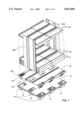
- FIG. 1. is a perspective view of a pallet system in accordance with the invention.
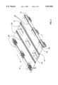
- FIG. 2 is a perspective view of a pallet cap in accordance with the invention.
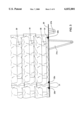
- FIG. 3 is a cross-sectional view of a loaded pallet system in accordance with the invention.
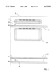
- FIG. 4 is a top detail view of a pallet cap in accordance with the invention.
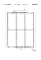
- FIG. 5 is a top view of a loaded pallet in accordance with the invention.
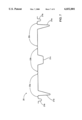
- FIG. 6 is a cross-sectional view of a stack of end plates in accordance with the invention.
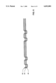
- FIG. 7 is a cross-sectional view of the pallet cap of FIG. 2.
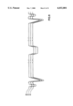
- FIG. 8 is a cross-sectional view of a stack of pallet caps in accordance with the invention.
- a pallet system based on a conventional pallet referred to here as the pallet base 10 is fitted with a pallet cap 20 to provide a pallet in accordance with the invention.
- the pallet may be a single integrated unit.
- the pallet system can be used, for example, to ship trays 30 such as those described in pending U.S. Pat. No. 5,816,406, which is incorporated by reference.
- FIG. 1 shows in an exploded view the relationship of elements of the pallet system.
- Several layers of trays are loaded onto the pallet, and the end plates 40a, 40b are respectively positioned at front and back ends of the load to help secure the load of trays 30 to each other and to the pallet, as well as to protect the ends of the trays and provide rigidity to the stack of trays.
- the entire load including the end plates 40a, 40b is wrapped with a film, either manually or using a machine and methods such as those described in U.S. Pat. Nos. 5,423,163 and 5,531,327.
- the pallet base 10 is a conventional plastic pallet. As shown, a conventional plastic pallet typically has pockets 11 that elevate the top surface of the pallet and provide recesses 12 which allow the pallet to be handled by standard equipment such as forklifts. Because the exact shape and placement of the pallet pockets 11 may vary among pallet models and manufacturers, the pallet cap 20 has pockets 21a, 21b, 21c customized to fit within the pockets 11 of a particular pallet 10.
- the pallet cap pockets 21a, 21b, 21c position the pallet cap 20 on the pallet base 10 and provide support for the weight of loads borne by the pallet cap 20.
- the pallet cap pocket 21a extends to the base of the pallet base pocket 11 to provide support and has ribbed walls to provide structural strength.
- Pallet cap pockets 21b and 21c are provided primarily for positioning the pallet cap 20 on the pallet base 10.
- the pallet cap 20 has raised, parallel guide rails 22, which are labelled in pairs 22a, 22b, 22c.
- the number of guide rails 22 may vary, depending on the size and shape of the trays to be loaded.
- FIG. 2 shows a pallet cap 20 having three pairs of guide rails 22a, 22b, 22c, designed for a load three trays wide, as is illustrated in FIG. 1.
- each tray 30 has side supports 31.
- the pairs of guide rails such as pair 22c, are sized and spaced so that when such a tray is loaded directly on the pallet cap 20, the tray side supports 31 closely straddle a pair of guide rails, thus constraining the lateral movement of the tray 30.
- the guide rails 22c help to position the tray 30, and as shown, also help to interlock adjacent trays 30.
- the top surface of pallet cap 20 is substantially open between the pair of guide rails 22c, which enables the open space to be used for packing items, in this case, eggs.
- the guide rails 22c avoid contact with the tray 30 or its load, and are raised above the level of the weight bearing surface of the pallet cap 20.
- the arrangement of parallel guide rails allows trays to be loaded onto the pallet by sliding the tray over a pair of guide rails from a front end of the pallet towards a back end, along the direction of the arrow 25 of FIG. 2.
- the opposite action may be used to unload trays from the pallet.
- the motion of a tray may be stopped by optional end stops 23, which are positioned at the outer edges of each pair of guide rails 22, towards the back end of the pallet. These end stops 23 limit the longitudinal movement of the trays parallel to the guide rails 22.
- FIG. 4 provides a more detailed illustration of the positions of the end stops 23.
- end plates 40a, 40b are vertically positioned at the front and back ends of the pallet as shown in FIG. 1. End plates are vertically positioned in one or more of the notches 24 found at both ends of each guide rail 22 (FIGS. 2 and 4). The notches 24 act as end plate holders for holding the end plates in position.
- End plates may provide greater stability to a stack of trays by being shaped to complement the shapes of the trays loaded onto the pallet.
- FIG. 5 shows a top view of a pallet loaded with trays 30 shaped like those described in U.S. Ser. No. 08/673,698.
- the end plates 40a, 40b are shaped to complement the contour of the tray edges.
- the end plates 40a, 40b at both ends of the pallet may be substantially identical or interchangeable.
- the end plates may be narrower than the pallet or load, as shown, and advantageously may be approximately 22 inches wide which allows them to be used with pallets and loads of different widths.
- a pallet having an industry standard size of 40 inches by 48 inches can support layers having two rows of three trays, where the trays are egg trays of a standard size, such as is disclosed in U.S. Ser. No. 08/673,698.
- pallets of other sizes can be used, including 24 inches by 48 inches (supporting two rows of two trays) and 36 inches by 24 inches (supporting one row of three trays).
- the end plates 40a, 40b shown in FIGS. 1 and 5 may be used for pallets having any of these dimensions.
- FIG. 6 illustrates a cross-section of a stack of end plates 40. As shown, the end plates may be shaped such that they nest within one another, which saves space when they are not being used.
- the components of the pallet system may be made of various materials.
- the pallet cap and end plates may be comprised of a plastic such as polypropylene or ABS plastic.
- FIG. 7 illustrates a cross-section of the pallet cap 20 shown in FIG. 2, created from a sheet of plastic having a thickness approximately in the range of 0.08-0.125 inches.
- the plastic sheet can be formed by methods such as thermo forming, rotomolding, and injection molding. The same thickness and methods apply to the end plates as well.
- the pallet system exemplified in the figures is customized for supporting egg trays described in U.S. Ser. No. 08/673,698.
- the side of the guide rails 22 likely to contact the portion of the tray 30 holding an egg have a slanted edge.
- the guide rails 22 have a width of approximately 0.5 inches, and at their highest point, have a height of approximately 0.25 inches. As shown, the guide rails 22 do not support the weight of the trays and their load.
- end stops 23 are provided at only one end of the guide rails 22, as shown in FIG. 2. Because the trays 30 have honeycomb-shaped edges, the inside surface of the end plate is shaped to complement this surface, as shown in FIG. 5. The raised portions of the end plate have a height of approximately 0.5 inches and a width of approximately 1 inch. As shown in FIG. 6, the end plates 40 are shaped such that they are interchangeable and nest within one another, which saves space when they are not being used. FIG. 8 illustrates that the pallet cap 20 is also shaped to allow several pallet caps to be nested within one another.
- the pallet may be a single integrated unit rather than a pallet cap fitting onto a conventional pallet.
- the sizes and positions of pallet cap pockets may vary.
- the length and height of guide rails, as well as the number of guide rails on a pallet may vary.
- the shapes and positions of the end stops may vary.
- end stops may be implemented as a continuous rail across the pallet surface. End stops may be provided at both ends of the pallet if trays are not slid onto the pallet. End plates may have a different width, such as the full width of a pallet.
Abstract
Description
Claims (28)
Priority Applications (3)
| Application Number | Priority Date | Filing Date | Title |
|---|---|---|---|
| US08/784,399 US6032801A (en) | 1997-01-17 | 1997-01-17 | Pallet system |
| CA002227106A CA2227106A1 (en) | 1997-01-17 | 1998-01-16 | Pallet system |
| US09/169,035 US6129505A (en) | 1996-06-25 | 1998-10-08 | Stacking trays |
Applications Claiming Priority (1)
| Application Number | Priority Date | Filing Date | Title |
|---|---|---|---|
| US08/784,399 US6032801A (en) | 1997-01-17 | 1997-01-17 | Pallet system |
Related Parent Applications (1)
| Application Number | Title | Priority Date | Filing Date |
|---|---|---|---|
| US08/892,811 Continuation-In-Part US5816406A (en) | 1996-06-25 | 1997-07-14 | Stacking trays |
Related Child Applications (1)
| Application Number | Title | Priority Date | Filing Date |
|---|---|---|---|
| US09/169,035 Continuation US6129505A (en) | 1996-06-25 | 1998-10-08 | Stacking trays |
Publications (1)
| Publication Number | Publication Date |
|---|---|
| US6032801A true US6032801A (en) | 2000-03-07 |
Family
ID=25132351
Family Applications (2)
| Application Number | Title | Priority Date | Filing Date |
|---|---|---|---|
| US08/784,399 Expired - Lifetime US6032801A (en) | 1996-06-25 | 1997-01-17 | Pallet system |
| US09/169,035 Expired - Lifetime US6129505A (en) | 1996-06-25 | 1998-10-08 | Stacking trays |
Family Applications After (1)
| Application Number | Title | Priority Date | Filing Date |
|---|---|---|---|
| US09/169,035 Expired - Lifetime US6129505A (en) | 1996-06-25 | 1998-10-08 | Stacking trays |
Country Status (2)
| Country | Link |
|---|---|
| US (2) | US6032801A (en) |
| CA (1) | CA2227106A1 (en) |
Cited By (15)
| Publication number | Priority date | Publication date | Assignee | Title |
|---|---|---|---|---|
| US20030121816A1 (en) * | 2001-12-27 | 2003-07-03 | Pigott Maurice J. | Palletized tray system |
| US20040058558A1 (en) * | 2002-07-11 | 2004-03-25 | Hitomi Sakurai | Manufacturing method for a semiconductor device |
| US6725783B2 (en) * | 2000-11-10 | 2004-04-27 | Fuji Photo Film Co., Ltd. | Pallet for stacking planographic printing plates thereon |
| US6725627B2 (en) | 1998-10-23 | 2004-04-27 | Southpac Trust Int'l., Inc. | Method of shipping preformed flower pot covers |
| WO2007073729A1 (en) * | 2005-12-24 | 2007-07-05 | Gebhardt Juergen | Trolley and transport pallet or transport receptacle therefor |
| US20090057182A1 (en) * | 2005-03-23 | 2009-03-05 | Fujifilm Corporation | Packaging arrangement and packaging method |
| US20090320410A1 (en) * | 2008-06-25 | 2009-12-31 | Weder Donald E | Method of transporting preformed flower pot covers |
| US20100043676A1 (en) * | 2008-08-22 | 2010-02-25 | Apps William P | Pallet with alignment features |
| DE102010013284A1 (en) * | 2010-03-29 | 2011-09-29 | Georg Utz Holding Ag | Shaped part for receiving and fixing rectangular in outline storage containers |
| CN103935606A (en) * | 2014-04-01 | 2014-07-23 | 熊世武 | Block and tile stacking platform |
| US20160249598A1 (en) * | 2016-05-02 | 2016-09-01 | Robert Savino | Mattress and Furniture Processor |
| CN109399226A (en) * | 2018-11-23 | 2019-03-01 | 东莞御膳坊信息技术有限公司 | A kind of dish dispensing box stacking recovering mechanism of automatic dish cooking machine |
| WO2019102274A1 (en) * | 2017-11-21 | 2019-05-31 | Giordano Poultry Plast S.P.A. | Unit for transporting eggs with intermediate partitions |
| US10676238B2 (en) * | 2018-11-11 | 2020-06-09 | Plasgad Plastic Products Acs Ltd | Anti-sagging devices and assemblies for racking pallets |
| US11377295B2 (en) * | 2016-09-08 | 2022-07-05 | Ozkor Pty. Ltd | Packaging assembly |
Families Citing this family (6)
| Publication number | Priority date | Publication date | Assignee | Title |
|---|---|---|---|---|
| US20060054528A1 (en) * | 2004-08-30 | 2006-03-16 | Sanzana Cecil M | Foldable plastic box, assemblable, having 5 cavities, with or without folding upper covers, to contain agricultural products |
| US7861673B2 (en) * | 2006-04-11 | 2011-01-04 | Life-Science Innovations, Llc | Egg incubation transport system and methods regarding same |
| US20090057304A1 (en) * | 2006-09-11 | 2009-03-05 | Lamarche Paul | Two piece container incorporating nesting characteristics and including interengageable hinge supports for upwardly supporting a lid upon a base |
| US7431171B2 (en) * | 2006-09-11 | 2008-10-07 | Lamarche Paul | Two piece container incorporating nesting characteristics and including interengageable hinge supports for upwardly supporting a lid upon a base |
| EA011134B1 (en) * | 2007-03-30 | 2008-12-30 | Открытое Акционерное Общество "Минский Завод Отопительного Оборудования" | Method of automatically controlled packing of sectional heating radiators in transfer pallet |
| NL2013569B1 (en) * | 2014-10-03 | 2016-07-07 | Agri-Invent B V | Method for hatching hatching eggs, hatcher holder for hatching hatching eggs, and use of such a hatcher holder. |
Citations (20)
| Publication number | Priority date | Publication date | Assignee | Title |
|---|---|---|---|---|
| DE281992C (en) * | ||||
| DE52101C (en) * | E. Ritter VON SKODA in Pilsen, Böhmen | Brake to regulate the closing movement of automatic weapons loading through the rear material | ||
| US3120825A (en) * | 1962-05-28 | 1964-02-11 | Associated Box Corp | Platform |
| US3229836A (en) * | 1964-08-07 | 1966-01-18 | California Portland Cement Co | Cement sack pallet and handling equipment |
| DE1252138B (en) * | 1967-10-12 | |||
| US3418792A (en) * | 1967-06-26 | 1968-12-31 | Koppers Co Inc | Modular collector electrode for electrostatic precipitators |
| US3720176A (en) * | 1970-08-13 | 1973-03-13 | Moraine Box Co | Molded pallet |
| US4226192A (en) * | 1979-01-05 | 1980-10-07 | Myers Douglas R | Pallet for transporting and displaying merchandise |
| US4416385A (en) * | 1980-12-23 | 1983-11-22 | Fairey Engineering Limited | Freight containers |
| US4480748A (en) * | 1981-08-24 | 1984-11-06 | Bigelow-Sanford, Inc. | Shipping pallet and container |
| US4558784A (en) * | 1984-07-23 | 1985-12-17 | Wallis Bernard J | Corrugated strip tray |
| US4921101A (en) * | 1989-09-11 | 1990-05-01 | Chrysler Corporation | Rack for sun roof modules |
| US5052307A (en) * | 1989-10-26 | 1991-10-01 | Viking Engineering & Development, Incorporated | Pallet tray system |
| US5205410A (en) * | 1992-03-16 | 1993-04-27 | Say Plastics | Loose-egg transport panel |
| US5421455A (en) * | 1994-08-09 | 1995-06-06 | Minnesota Mining And Manufacturing Company | Locking clip for IC trays |
| US5423163A (en) * | 1993-08-23 | 1995-06-13 | Iron Eagle, Inc. | Free standing pallet wrapping apparatus |
| US5487471A (en) * | 1994-10-19 | 1996-01-30 | Molex Incorporated | Packaging container assembly for electrical connector components |
| US5531327A (en) * | 1994-11-02 | 1996-07-02 | T.H.E.M. Industries, Inc. | Pallet system including end panels |
| US5569693A (en) * | 1995-06-05 | 1996-10-29 | Borden Inc. | High stretch film for pallet wrapping |
| US5694836A (en) * | 1996-12-10 | 1997-12-09 | Cool Eggspress | Modular loose egg cooling, storage and transport system and method |
Family Cites Families (7)
| Publication number | Priority date | Publication date | Assignee | Title |
|---|---|---|---|---|
| US1112943A (en) * | 1913-04-02 | 1914-10-06 | American Hardware Corp | Drag-box. |
| FR1316361A (en) * | 1962-03-01 | 1963-01-25 | Trait D Union Ind Et Commercia | Packing boxes which can, by assembly, form a storage unit |
| FR95461E (en) * | 1966-01-10 | 1971-01-15 | Wodli Emile | Storage set consisting of stackable bins and bins for such a set. |
| US3734309A (en) * | 1970-11-27 | 1973-05-22 | Plastics Inc | Double stack interlocking trays |
| SE413764B (en) * | 1976-04-22 | 1980-06-23 | Fisklaadan Packing Ab | WORK FOR A CHARGE |
| SU1733340A1 (en) * | 1989-08-16 | 1992-05-15 | Клуб Самодеятельного Технического Творчества Тырныаузского Вольфрамо-Молибденового Комбината | Food container |
| US5964350A (en) * | 1998-02-24 | 1999-10-12 | Lamarche; Paul | Assembly of interconnected containers and containers for use therein |
-
1997
- 1997-01-17 US US08/784,399 patent/US6032801A/en not_active Expired - Lifetime
-
1998
- 1998-01-16 CA CA002227106A patent/CA2227106A1/en not_active Abandoned
- 1998-10-08 US US09/169,035 patent/US6129505A/en not_active Expired - Lifetime
Patent Citations (20)
| Publication number | Priority date | Publication date | Assignee | Title |
|---|---|---|---|---|
| DE281992C (en) * | ||||
| DE52101C (en) * | E. Ritter VON SKODA in Pilsen, Böhmen | Brake to regulate the closing movement of automatic weapons loading through the rear material | ||
| DE1252138B (en) * | 1967-10-12 | |||
| US3120825A (en) * | 1962-05-28 | 1964-02-11 | Associated Box Corp | Platform |
| US3229836A (en) * | 1964-08-07 | 1966-01-18 | California Portland Cement Co | Cement sack pallet and handling equipment |
| US3418792A (en) * | 1967-06-26 | 1968-12-31 | Koppers Co Inc | Modular collector electrode for electrostatic precipitators |
| US3720176A (en) * | 1970-08-13 | 1973-03-13 | Moraine Box Co | Molded pallet |
| US4226192A (en) * | 1979-01-05 | 1980-10-07 | Myers Douglas R | Pallet for transporting and displaying merchandise |
| US4416385A (en) * | 1980-12-23 | 1983-11-22 | Fairey Engineering Limited | Freight containers |
| US4480748A (en) * | 1981-08-24 | 1984-11-06 | Bigelow-Sanford, Inc. | Shipping pallet and container |
| US4558784A (en) * | 1984-07-23 | 1985-12-17 | Wallis Bernard J | Corrugated strip tray |
| US4921101A (en) * | 1989-09-11 | 1990-05-01 | Chrysler Corporation | Rack for sun roof modules |
| US5052307A (en) * | 1989-10-26 | 1991-10-01 | Viking Engineering & Development, Incorporated | Pallet tray system |
| US5205410A (en) * | 1992-03-16 | 1993-04-27 | Say Plastics | Loose-egg transport panel |
| US5423163A (en) * | 1993-08-23 | 1995-06-13 | Iron Eagle, Inc. | Free standing pallet wrapping apparatus |
| US5421455A (en) * | 1994-08-09 | 1995-06-06 | Minnesota Mining And Manufacturing Company | Locking clip for IC trays |
| US5487471A (en) * | 1994-10-19 | 1996-01-30 | Molex Incorporated | Packaging container assembly for electrical connector components |
| US5531327A (en) * | 1994-11-02 | 1996-07-02 | T.H.E.M. Industries, Inc. | Pallet system including end panels |
| US5569693A (en) * | 1995-06-05 | 1996-10-29 | Borden Inc. | High stretch film for pallet wrapping |
| US5694836A (en) * | 1996-12-10 | 1997-12-09 | Cool Eggspress | Modular loose egg cooling, storage and transport system and method |
Cited By (24)
| Publication number | Priority date | Publication date | Assignee | Title |
|---|---|---|---|---|
| US6725627B2 (en) | 1998-10-23 | 2004-04-27 | Southpac Trust Int'l., Inc. | Method of shipping preformed flower pot covers |
| US6725783B2 (en) * | 2000-11-10 | 2004-04-27 | Fuji Photo Film Co., Ltd. | Pallet for stacking planographic printing plates thereon |
| US20030121816A1 (en) * | 2001-12-27 | 2003-07-03 | Pigott Maurice J. | Palletized tray system |
| US20040026283A1 (en) * | 2001-12-27 | 2004-02-12 | Pigott Maurice J. | Palletized tray system |
| US6874637B2 (en) * | 2001-12-27 | 2005-04-05 | Orbis Corporation | Palletized tray system |
| US7152738B2 (en) | 2001-12-27 | 2006-12-26 | Orbis Corporation | Palletized tray system |
| US20040058558A1 (en) * | 2002-07-11 | 2004-03-25 | Hitomi Sakurai | Manufacturing method for a semiconductor device |
| US20090057182A1 (en) * | 2005-03-23 | 2009-03-05 | Fujifilm Corporation | Packaging arrangement and packaging method |
| WO2007073729A1 (en) * | 2005-12-24 | 2007-07-05 | Gebhardt Juergen | Trolley and transport pallet or transport receptacle therefor |
| US20090320410A1 (en) * | 2008-06-25 | 2009-12-31 | Weder Donald E | Method of transporting preformed flower pot covers |
| US20110011033A1 (en) * | 2008-06-25 | 2011-01-20 | Weder Donald E | Method of transporting preformed flower pot covers |
| US7836665B2 (en) | 2008-06-25 | 2010-11-23 | Wanda M. Weder & Bill F. Straeter | Method of transporting preformed flower pot covers |
| EP2159157A3 (en) * | 2008-08-22 | 2010-03-31 | Rehrig Pacific Company | Pallet |
| EP2159157A2 (en) * | 2008-08-22 | 2010-03-03 | Rehrig Pacific Company | Pallet |
| US20100043676A1 (en) * | 2008-08-22 | 2010-02-25 | Apps William P | Pallet with alignment features |
| US8291839B2 (en) | 2008-08-22 | 2012-10-23 | Rehrig Pacific Company | Pallet with alignment features |
| DE102010013284A1 (en) * | 2010-03-29 | 2011-09-29 | Georg Utz Holding Ag | Shaped part for receiving and fixing rectangular in outline storage containers |
| CN103935606A (en) * | 2014-04-01 | 2014-07-23 | 熊世武 | Block and tile stacking platform |
| US20160249598A1 (en) * | 2016-05-02 | 2016-09-01 | Robert Savino | Mattress and Furniture Processor |
| US11377295B2 (en) * | 2016-09-08 | 2022-07-05 | Ozkor Pty. Ltd | Packaging assembly |
| WO2019102274A1 (en) * | 2017-11-21 | 2019-05-31 | Giordano Poultry Plast S.P.A. | Unit for transporting eggs with intermediate partitions |
| US11685595B2 (en) * | 2017-11-21 | 2023-06-27 | Giordano Poultry Plast S.P.A. | Unit for transporting eggs with intermediate partitions |
| US10676238B2 (en) * | 2018-11-11 | 2020-06-09 | Plasgad Plastic Products Acs Ltd | Anti-sagging devices and assemblies for racking pallets |
| CN109399226A (en) * | 2018-11-23 | 2019-03-01 | 东莞御膳坊信息技术有限公司 | A kind of dish dispensing box stacking recovering mechanism of automatic dish cooking machine |
Also Published As
| Publication number | Publication date |
|---|---|
| CA2227106A1 (en) | 1998-07-17 |
| US6129505A (en) | 2000-10-10 |
Similar Documents
| Publication | Publication Date | Title |
|---|---|---|
| US6032801A (en) | Pallet system | |
| US3524415A (en) | Plastic shipping tray | |
| US5103976A (en) | Tray for integrated circuits with supporting ribs | |
| US4880116A (en) | Robotic accessible wafer shipper assembly | |
| US4817795A (en) | Robotic accessible wafer shipper assembly | |
| US3315800A (en) | Collapsible plywood shipping device | |
| US4798305A (en) | Adjustable shipping tray | |
| US2841350A (en) | Loading pallet | |
| US4752007A (en) | Disk shipper | |
| CZ387690A3 (en) | Pallet | |
| EP0613829B1 (en) | Can end tray | |
| EP0939731B1 (en) | Stacking trays | |
| WO1997049612A9 (en) | Stacking trays | |
| US20130017054A1 (en) | Package unit and loading method and loading structure therefor | |
| JP3005187B2 (en) | Honeycomb structure packing box | |
| KR101347918B1 (en) | Transport container with improved ventilation properties for flowers | |
| JP2004042964A (en) | Packaging container for honeycomb-shaped structure, and transporting method for honeycomb-shaped structure | |
| CN210681460U (en) | Tray | |
| JP5401983B2 (en) | Assembled container | |
| US4254867A (en) | Package and method for transporting loose brick | |
| KR890003667B1 (en) | Shipping pallet | |
| CN216547286U (en) | Tray | |
| RU212386U1 (en) | ARCHIVE PALLET | |
| CN215323901U (en) | Tray and packaging structure for storage battery transportation | |
| AU2010226639A1 (en) | Egg transport system |
Legal Events
| Date | Code | Title | Description |
|---|---|---|---|
| AS | Assignment |
Owner name: JUPILLE DESIGN INCORPORATED, CALIFORNIA Free format text: ASSIGNMENT OF ASSIGNORS INTEREST;ASSIGNORS:JUPILLE, HENRY;TOSTENSON, DAVID JAMES;REEL/FRAME:008877/0613 Effective date: 19971113 |
|
| STCF | Information on status: patent grant |
Free format text: PATENTED CASE |
|
| FEPP | Fee payment procedure |
Free format text: PAYOR NUMBER ASSIGNED (ORIGINAL EVENT CODE: ASPN); ENTITY STATUS OF PATENT OWNER: LARGE ENTITY |
|
| FPAY | Fee payment |
Year of fee payment: 4 |
|
| FEPP | Fee payment procedure |
Free format text: PAYER NUMBER DE-ASSIGNED (ORIGINAL EVENT CODE: RMPN); ENTITY STATUS OF PATENT OWNER: LARGE ENTITY |
|
| FPAY | Fee payment |
Year of fee payment: 8 |
|
| REMI | Maintenance fee reminder mailed | ||
| FEPP | Fee payment procedure |
Free format text: PAYOR NUMBER ASSIGNED (ORIGINAL EVENT CODE: ASPN); ENTITY STATUS OF PATENT OWNER: LARGE ENTITY |
|
| FPAY | Fee payment |
Year of fee payment: 12 |