US6032876A - Apparatus for forming liquid droplets having a mechanically fixed inner microtube - Google Patents
Apparatus for forming liquid droplets having a mechanically fixed inner microtube Download PDFInfo
- Publication number
- US6032876A US6032876A US09/203,907 US20390798A US6032876A US 6032876 A US6032876 A US 6032876A US 20390798 A US20390798 A US 20390798A US 6032876 A US6032876 A US 6032876A
- Authority
- US
- United States
- Prior art keywords
- microtube
- exit end
- wall
- intermediate space
- annular intermediate
- Prior art date
- Legal status (The legal status is an assumption and is not a legal conclusion. Google has not performed a legal analysis and makes no representation as to the accuracy of the status listed.)
- Expired - Lifetime
Links
Images


Classifications
-
- H—ELECTRICITY
- H01—ELECTRIC ELEMENTS
- H01J—ELECTRIC DISCHARGE TUBES OR DISCHARGE LAMPS
- H01J49/00—Particle spectrometers or separator tubes
- H01J49/02—Details
- H01J49/04—Arrangements for introducing or extracting samples to be analysed, e.g. vacuum locks; Arrangements for external adjustment of electron- or ion-optical components
- H01J49/0431—Arrangements for introducing or extracting samples to be analysed, e.g. vacuum locks; Arrangements for external adjustment of electron- or ion-optical components for liquid samples
-
- B—PERFORMING OPERATIONS; TRANSPORTING
- B05—SPRAYING OR ATOMISING IN GENERAL; APPLYING FLUENT MATERIALS TO SURFACES, IN GENERAL
- B05B—SPRAYING APPARATUS; ATOMISING APPARATUS; NOZZLES
- B05B15/00—Details of spraying plant or spraying apparatus not otherwise provided for; Accessories
- B05B15/60—Arrangements for mounting, supporting or holding spraying apparatus
-
- B—PERFORMING OPERATIONS; TRANSPORTING
- B05—SPRAYING OR ATOMISING IN GENERAL; APPLYING FLUENT MATERIALS TO SURFACES, IN GENERAL
- B05B—SPRAYING APPARATUS; ATOMISING APPARATUS; NOZZLES
- B05B5/00—Electrostatic spraying apparatus; Spraying apparatus with means for charging the spray electrically; Apparatus for spraying liquids or other fluent materials by other electric means
- B05B5/025—Discharge apparatus, e.g. electrostatic spray guns
- B05B5/0255—Discharge apparatus, e.g. electrostatic spray guns spraying and depositing by electrostatic forces only
-
- B—PERFORMING OPERATIONS; TRANSPORTING
- B05—SPRAYING OR ATOMISING IN GENERAL; APPLYING FLUENT MATERIALS TO SURFACES, IN GENERAL
- B05B—SPRAYING APPARATUS; ATOMISING APPARATUS; NOZZLES
- B05B7/00—Spraying apparatus for discharge of liquids or other fluent materials from two or more sources, e.g. of liquid and air, of powder and gas
- B05B7/02—Spray pistols; Apparatus for discharge
- B05B7/06—Spray pistols; Apparatus for discharge with at least one outlet orifice surrounding another approximately in the same plane
- B05B7/062—Spray pistols; Apparatus for discharge with at least one outlet orifice surrounding another approximately in the same plane with only one liquid outlet and at least one gas outlet
- B05B7/066—Spray pistols; Apparatus for discharge with at least one outlet orifice surrounding another approximately in the same plane with only one liquid outlet and at least one gas outlet with an inner liquid outlet surrounded by at least one annular gas outlet
- B05B7/068—Spray pistols; Apparatus for discharge with at least one outlet orifice surrounding another approximately in the same plane with only one liquid outlet and at least one gas outlet with an inner liquid outlet surrounded by at least one annular gas outlet the annular gas outlet being supplied by a gas conduit having an axially concave curved internal surface just upstream said outlet
-
- G—PHYSICS
- G01—MEASURING; TESTING
- G01N—INVESTIGATING OR ANALYSING MATERIALS BY DETERMINING THEIR CHEMICAL OR PHYSICAL PROPERTIES
- G01N30/00—Investigating or analysing materials by separation into components using adsorption, absorption or similar phenomena or using ion-exchange, e.g. chromatography or field flow fractionation
- G01N30/02—Column chromatography
- G01N30/62—Detectors specially adapted therefor
- G01N30/72—Mass spectrometers
- G01N30/7233—Mass spectrometers interfaced to liquid or supercritical fluid chromatograph
- G01N30/724—Nebulising, aerosol formation or ionisation
- G01N30/7246—Nebulising, aerosol formation or ionisation by pneumatic means
-
- H—ELECTRICITY
- H01—ELECTRIC ELEMENTS
- H01J—ELECTRIC DISCHARGE TUBES OR DISCHARGE LAMPS
- H01J49/00—Particle spectrometers or separator tubes
- H01J49/02—Details
- H01J49/10—Ion sources; Ion guns
- H01J49/16—Ion sources; Ion guns using surface ionisation, e.g. field-, thermionic- or photo-emission
- H01J49/165—Electrospray ionisation
- H01J49/167—Capillaries and nozzles specially adapted therefor
-
- B—PERFORMING OPERATIONS; TRANSPORTING
- B05—SPRAYING OR ATOMISING IN GENERAL; APPLYING FLUENT MATERIALS TO SURFACES, IN GENERAL
- B05B—SPRAYING APPARATUS; ATOMISING APPARATUS; NOZZLES
- B05B13/00—Machines or plants for applying liquids or other fluent materials to surfaces of objects or other work by spraying, not covered by groups B05B1/00 - B05B11/00
- B05B13/02—Means for supporting work; Arrangement or mounting of spray heads; Adaptation or arrangement of means for feeding work
- B05B13/0278—Arrangement or mounting of spray heads
-
- B—PERFORMING OPERATIONS; TRANSPORTING
- B05—SPRAYING OR ATOMISING IN GENERAL; APPLYING FLUENT MATERIALS TO SURFACES, IN GENERAL
- B05B—SPRAYING APPARATUS; ATOMISING APPARATUS; NOZZLES
- B05B7/00—Spraying apparatus for discharge of liquids or other fluent materials from two or more sources, e.g. of liquid and air, of powder and gas
- B05B7/02—Spray pistols; Apparatus for discharge
- B05B7/08—Spray pistols; Apparatus for discharge with separate outlet orifices, e.g. to form parallel jets, i.e. the axis of the jets being parallel, to form intersecting jets, i.e. the axis of the jets converging but not necessarily intersecting at a point
- B05B7/0876—Spray pistols; Apparatus for discharge with separate outlet orifices, e.g. to form parallel jets, i.e. the axis of the jets being parallel, to form intersecting jets, i.e. the axis of the jets converging but not necessarily intersecting at a point to form parallel jets constituted by a liquid or a mixture containing a liquid
-
- G—PHYSICS
- G01—MEASURING; TESTING
- G01N—INVESTIGATING OR ANALYSING MATERIALS BY DETERMINING THEIR CHEMICAL OR PHYSICAL PROPERTIES
- G01N30/00—Investigating or analysing materials by separation into components using adsorption, absorption or similar phenomena or using ion-exchange, e.g. chromatography or field flow fractionation
- G01N30/02—Column chromatography
- G01N30/84—Preparation of the fraction to be distributed
- G01N2030/8447—Nebulising, aerosol formation or ionisation
- G01N2030/847—Nebulising, aerosol formation or ionisation by pneumatic means
Definitions
- This invention relates generally to apparatus for forming liquid droplets, such as liquid sprayers, atomizers, and the like. More particularly, this invention relates to nebulizers useful in liquid chromatography (LC) or capillary electrophoresis (CE) coupled with an analytical system, such as a mass spectrometer (MS).
- LC liquid chromatography
- CE capillary electrophoresis
- MS mass spectrometer
- Micro nebulizers have been used to convert liquid samples to fine droplets suitable for analysis.
- Micro nebulizers provide a useful interface for analytical systems based on techniques such as mass spectrometry (MS), atomic absorption (AA), or inductively coupled plasma (ICP) which cannot directly analyze liquid samples.
- MS mass spectrometry
- AA atomic absorption
- ICP inductively coupled plasma
- the liquid sample must first be converted to a gas.
- the ideal conversion would, theoretically, involve spraying the liquid into uniform fine droplets.
- the uniform fine droplets then would then be dried and converted to a gas suitable for analysis.
- uniform fine droplets are difficult to attain. If droplets vary in size, the heat necessary to dry a larger droplet damages the analyte in a finer droplet. Large droplets, if left undried, result in noise and signal interference.
- the inner microtube carries the liquid sample; the outer microtube carries an inert fluid (liquid or gas) used as a sheath fluid.
- the liquid sample and the sheath fluid collide and the liquid sample is broken into droplets by the shearing force of the sheath fluid.
- Uniform laminar sheath fluid flow is critical to producing uniform size droplets. Any imperfections in the annular region between the inner and outer microtubes forming the sheath fluid flow region create turbulence in the sheath fluid, which translates directly into lack of control of droplet size and uniformity. Such imperfections may be generated, for example, by transition points within the sheath fluid flow region such as at the point the sheath fluid is introduced into the outer microtube.
- nebulizers with microtubes of relatively great length have been used.
- the increase in microtube length permits the sheath fluid to stabilize after the turbulence induced by internal imperfections in the sheath fluid entry point transition.
- increased microtube length alone fails to solve the problem entirely or even satisfactorily.
- Long microtubes dissipate the energy needed for the shearing force collision of sheath fluid and the liquid sample. More problematic is that long concentric microtubes do not stay centered relative to each other; thus, the exit aperture experienced by the sheath fluid is either asymmetrical, changes with time, or both.
- the velocity and shearing force of the sheath fluid experienced by the liquid sample is unevenly distributed and changes with time, which brings about the problem that plagues current nebulizers: namely, variation in size and uniformity of the droplets produced.
- a nebulizer that reproducibly generates uniform fine droplets of controllable size and distribution. Further, what is needed is a nebulizer wherein the aperture experienced by the sheath fluid is controllable. Also desirable is a nebulizer wherein the inner microtube or needle is mechanically stabilized and wherein such stabilizer elements do not substantially impede the sheath fluid flow in the outer microtube. Further, what is needed is a nebulizer wherein the sheath fluid flow path is sufficiently short and smooth such that the reduction of energy associated with liquid droplet formation occurs substantially at or near the point of nebulization.
- the invention provides an apparatus for forming droplets from a liquid comprising:
- an outer microtube having an inner wall, an exit end, and an exit end aperture, wherein the inner microtube has an outer diameter smaller than the inner diameter of the outer microtube, and the inner microtube is positioned within and is surrounded by the outer microtube such that an annular intermediate space is formed therebetween, with the exit end of each microtube being located at a same end of the apparatus,
- one or more intermediate structures either (i) extending inward radially from the inner wall of the outer microtube and contacting the outer wall of the inner microtube for a predetermined length, (ii) extending outward radially from the outer wall of the inner microtube and contacting the inner wall of the outer microtube for a predetermined length, or (iii) spanning the annular intermediate space and contacting both the outer wall of the inner microtube and the inner wall of the outer microtube for a predetermined length, wherein the intermediate structure is situated so as to mechanically stabilize the inner microtube, and
- one or more communicating channels continuing lengthwise along the outside of the inner microtube, wherein the communicating channel provides a continuation of the annular intermediate space and through which a fluid may continue to flow after encountering the intermediate structure.
- the invention provides a nebulizer assembly, comprising:
- an outer microtube having an exit end adapted for coupling with a tip and an exit end aperture, wherein the inner microtube has an outer diameter smaller than the inner diameter of the outer microtube, and the inner microtube is positioned within and is surrounded by the outer microtube such that an annular intermediate space is formed therebetween, with the exit end of each microtube being located at a same end of the nebulizer assembly, and
- two or more inner microtubes are included within the apparatus or nebulizer assembly, such that multiple annular intermediate spaces for fluid flow are formed.
- the invention provides an apparatus such as a nebulizer that reproducibly generates uniform droplets of controllable size and distribution. Further, the invention provides an apparatus wherein the aperture experienced by the sheath fluid is controllable. The invention further provides an apparatus wherein the inner microtube or needle is mechanically stabilized and wherein such stabilizer elements do not substantially impede sheath fluid flow in the outer microtube. Further, the apparatus taught herein provides a sheath fluid flow path which is sufficiently short and smooth such that the reduction of energy associated with liquid droplet formation occurs substantially at or near the point of nebulization.
- the apparatus described above may be coupled to any analytical system in order that droplets produced by the apparatus may be analyzed.
- the apparatus is coupled to a mass spectrometer.
- the invention is particularly useful as part of an interface for mass spectrometers employing, for example, electrospray ionization (ESI) or atmospheric pressure chemical ionization (APCI) to analyze liquid samples.
- ESI electrospray ionization
- APCI atmospheric pressure chemical ionization
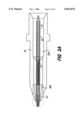
- FIG. 1, A through C schematically illustrates a nebulizer assembly according to the present invention.
- FIG. 1A is an enlarged schematic of the inner stabilizer portion of a nebulizer
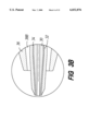
- FIG. 1B is a cross section of the nebulizer of FIG. 1A taken along axis AA;
- FIG. 1C is an enlarged view of the tip of the nebulizer assembly of FIG. 1A.
- FIG. 2 illustrates the tip and outer microtube components of an embodiment of the invention taught herein.
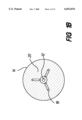
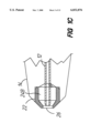
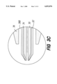
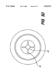
- FIG. 3 illustrates embodiments of the invention employing two inner microtubes and an outer microtube.
- FIG. 4 illustrates the angle, a, formed by the intersection of the center axis of the inner microtube and a line drawn tangent to the chamfer on the outer wall of the inner microtube.
- FIG. 5, A and B respectively, illustrates an alternate embodiment of the invention (controlled asymmetrical flow) and an end section thereof.
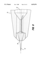
- FIG. 6 schematically illustrates an alternate embodiment of the present invention (CE/MS extended needle with liquid sheath flow).
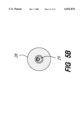
- FIG. 7 illustrates representative results obtainable by the nebulizer of FIG. 1 under conventional APCI conditions.
- the invention provides an improved apparatus for reproducibly forming and controlling size and uniformity of droplets from a liquid.
- the invention provides radial and angular control of sheath fluid flow paths and exit apertures, thereby producing controlled sheath fluid flow velocity and distribution and resultant droplet size and uniformity.
- the apparatus has a mechanically stabilized inner microtube or needle, which is provided by securing in a predetermined fixed position the inner microtube, such as by narrowing the inner diameter of the outer microtube or otherwise narrowing the annular intermediate space between the inner and outer microtubes for a predetermined length.
- the inner microtube is secured in a centered or otherwise predetermined fixed position, with minimum perturbation of the sheath fluid flow.
- an optional tip when coupled with a surface at the exit end of the outer microtube, provides a region in which the sheath fluid flow from the outer microtube stabilizes prior to both exiting the tip and colliding with the liquid sample (analyte) exiting the inner microtube.
- the invention provides an apparatus comprised of at least one inner microtube and an outer microtube, the inner microtube positioned within and surrounded by the outer microtube and defining an inter tube annular intermediate space therebetween.
- the inner and outer microtubes are positioned in a concentric arrangement about a common central axis.
- it is operable and in certain embodiments it may be desirable to "offset" the position of the inner and outer microtubes in an eccentric arrangement about substantially parallel axes, such as illustrated in FIG. 5.
- Each microtube has an exit end and an exit end aperture, through which fluid flows out of each of the microtubes.
- the liquid sample or analyte flows through the inside of the inner microtube, while the sheath fluid flows inside of the outer microtube and outside of the inner microtube within the annular intermediate space.
- the sheath fluid flows inside of the outer microtube and outside of the inner microtube within the annular intermediate space.
- multiple annular intermediate spaces are formed, wherein more than one sheath fluid or a make-up fluid may be employed.
- the outer microtube is adapted so that for at least a portion of its length, the annular intermediate space is reduced to one or more fluid communicating channels and the remainder of the annular intermediate space comprises one or more intermediate structures.
- the inner microtube is secured in a substantially fixed radial position by providing an intermediate stabilizing brace-like, extension-type, or bridging structure in the annular intermediate space formed between the inner microtube and the outer microtube.
- the intermediate structure is generally fluid impermeable and extends for a predetermined portion of the length of the outer microtube and mechanically provides support for the inner microtube, stabilizing the inner microtube into a fixed radial position and optionally a fixed axial position.
- the brace-like intermediate structure extends inward and contacts the outer wall of the inner microtube.
- the intermediate structure may be provided by an extension radially outward from the outer wall of the inner microtube contacting or sealably abutting the inner wall of the outer microtube.
- the intermediate structure bridges or spans the annular intermediate space and contacts both the outer wall of the inner microtube and the inner wall of the outer microtube.
- the annular intermediate space also contains one or more preferably substantially parallel fluid communicating channels continuing lengthwise for a portion of the outer microtube, which permit sheath fluid flow therethrough.
- the intermediate structure serves the function of stabilizing the inner microtube by restricting radial movement of the inner microtube, while at the same time permitting sheath fluid flow by virtue of a preferably substantially parallel channel or channels communicating with the annular intermediate space on either side of the stabilizing intermediate structure.
- the outermost inner microtube that is, the inner microtube closest to the outer microtube, is mechanically stabilized.
- a preferred nebulizer assembly in accordance with the present invention comprises an inner microtube 12 having a first exit end aperture and an outer microtube 14 surrounding the inner microtube 12 and defining an inter tube annular intermediate space 24A therebetween.
- the outer microtube 14 has a second exit end aperture at the same end of the nebulizer assembly and preferably at about the same place as the first exit end aperture of the inner microtube 12.
- the outer microtube 14 has, for a lengthwise portion 16 of the outer microtube preferably extending up to about 1.1 mm from the second exit end aperture, a reduction of the annular intermediate space to one or more fluid communicating channels (FIG. 1B, 18).
- the reduction of the annular intermediate space is provided by means of one or more substantially impermeable intermediate structures 20 which extend from the inner wall of the outer microtube 14.
- the intermediate structure or extension 20 contacts the outer wall of the inner microtube 12 for a predetermined length and functions to mechanically fix in radial position the inner microtube 12.
- the channel 18 provides the only means for passage of sheath fluid continuing lengthwise along the outside of the inner microtube and provides a continuation of the annular intermediate space between the outer microtube 14 and inner microtube 12 through which sheath fluid may continue to flow after encountering the intermediate structure or extension 20 which effectively narrows the annular intermediate space.
- the invention further provides a tip which, when coupled with a surface at the exit end of the outer microtube, provides a region into which the sheath fluid flow from the outer microtube (restricted to the communicating channels between the intermediate structure) may expand and establish stable fluid flow dynamics (wherein both gas and liquid are termed a fluid for purposes of this invention).
- a tip is desirable for the following reasons.
- Sheath fluid flow within the annular intermediate space prior to encountering the intermediate structure is preferably laminar. Turbulence may occur as the sheath fluid passes through the communicating channel(s). Nebulizing shearing forces would be adversely affected if the sheath fluid flow were not laminar.
- the tip when coupled to a surface at the exit end of the outer microtube, provides a region into which the sheath fluid may flow and reestablish laminar flow prior to nebulization.
- the stable (laminar) sheath fluid flow contributes to efficient droplet formation by permitting the energy of the sheath fluid molecules, at the point of nebulization, to pass to the liquid and result in droplet formation, rather than being dissipated in friction inside the microtubes.
- the tip upon coupling with a surface at the exit end of the outer microtube, encircles the inner microtube and preferably provides for a length of about 1.0 mm of an annular intermediate space similar to that of the first portion of the outer microtube, providing thereby a buffer space within which the sheath fluid flow can restabilize prior to exiting through the tip orifice.
- an insertable cap or tip 22 couples pressably with a surface at the exit end of the outer microtubes 14, encircling the inner microtube 12 and providing an annular intermediate space 24B between the inner wall of the tip 22 and the outer wall of the inner microtube 12 for a length of about 1.0 mm.
- the tip 22 provides conditions amenable to stabilized fluid (gas or liquid) dynamics, an effective "buffer" region, within which fluid flow may stabilize or optimize prior to exiting through the tip end orifice 26.
- FIG. 2 illustrates the receiving end 28 of the outer microtube 14 adaptably configured in order to receive the insertable tip 22.
- the tip may be configured as a cap or extendable sleeve (not shown), which mounts onto or over and around the outer microtube 14.
- the insertable tip illustrated in FIG. 2 is preferred for production purposes.
- the exit end of the inner microtube may protrude beyond (as illustrated in FIG. 6), be flush with, or be recessed with respect to (as illustrated in FIG. 1) the exit end of the outer microtube.
- the exit end of the inner microtube is preferably recessed with respect to the exit end of the outer microtube.
- the exit end of the inner microtube preferably is flush with or protrudes beyond the exit end of the outer microtube.
- all, some, or one of the outside surfaces of the tip, the exit ends of the inner microtube(s), and the exit end of the outer microtube are preferably chamfered, angled, or otherwise tapered. Tapering the inner microtubes may be particularly important with low liquid sample flowrates such as experienced in CE-MS. For example, in CE-MS applications, tapering the inner microtubes assists in focussing the generated electrical field, thus improving sensitivity and stability at low liquid sample flowrates.
- the position of the inner microtube, while fixed in the radial direction relative to the outer microtube is adjustable along its longitudinal axis by providing an adjustment means such as a threaded coupling to the inner microtube.
- the nebulizer comprises two inner microtubes.
- the first inner microtube 30 is positioned within and surrounded by the second inner microtube 32, thus defining a first inter tube annular intermediate space 34 therebetween.
- the second inner microtube 32 is positioned within and surrounded by the outer microtube 36, thus defining a second inter tube annular intermediate space 38A and 38B therebetween and having four (4) radial communicating channels 44.
- Each microtube has an exit end and an exit end aperture, through which fluid flows out of each of the microtubes.
- the liquid sample or analyte flows through the inside of the first inner microtube 30, while a sheath fluid or make-up fluid flows inside of the second inner microtube 32 and outside the first inner microtube 30 within the first annular intermediate space 34.
- a sheath fluid flows inside of the outer microtube 36 and outside the second inner microtube 32 within the second annular intermediate space 38A and 38B.
- the embodiment illustrated in FIG. 3 also comprises intermediate structures 40 and a tip 42, as discussed herein above.
- FIG. 3B depicts an enlarged view of the exit end of the nebulizer.
- the first and second inner microtubes 30 and 32 are tapered to increase the electrical field gradient at the tip 42 in order to assist in Taylor cone formation of the electrosprayed liquid sample.
- the first annular intermediate space 34 is shown, as well as the details of tapering at the exit ends of the first and second inner microtubes 30 and 32.
- FIG. 3C depicts an enlarged view of an alternative embodiment using different tapering geometries for the first and second inner microtubes 30 and 32 for easier fabrication, relaxed assembly tolerances, and improved stability.
- the first inner microtube 30 protrudes from the exit end of the second inner microtube 32 to help initiate the Taylor cone and to avoid signal instability.
- the first inner microtube is fabricated from glass and the second inner microtube is fabricated from metal such as stainless steel and serves as the terminating CE electrode.
- the CE current would cause bubble formation, resulting in undesirable signal instability.
- the maximum acceptable protrusion of the first inner microtube past the second inner microtube is limited by the confines of the sides of the fully formed Taylor cone at the desired liquid sample flowrate.
- FIG. 3 is particularly useful, for example, in CE-MS, wherein make-up fluid, typically a liquid, is employed in the first annular intermediate space 34 and a sheath fluid, typically a gas, is employed in the second annular intermediate space 38A and 38B.
- make-up fluid typically a liquid
- sheath fluid typically a gas
- the outer microtube comprises an originally solid stainless steel rod drilled out to an inner diameter of about 1.6 mm on one end to a depth of about 12 mm. The other end of the rod is drilled out to approximately the same inner diameter for a depth of about 1 mm.
- a center hole is drilled of sufficient diameter to accommodate the inner microtube; multiple channels extending radially, for example three (3) or four (4), are drilled or otherwise machined, optionally each equidistant from the other.
- Such a geometry may be selected to promote balanced sheath fluid flow, as well as to provide for easy and certain insertion of the needle-like inner microtube into the outer microtube of the nebulizer.
- the radial openings are sufficiently narrow in opening width so as not to permit the inner microtube or needle to pass anywhere but directly into the center hole.
- EDM fine wire electrical discharge machining
- a plunge quill technique may be used but is slower and more costly.
- the invention is not limited to an intermediate stabilizing structure provided by means of drilling out the outer microtube. It is also possible to adapt the inner needle or microtube so as to provide projections from the outside wall of the inner needle or microtube. These projections provide the intermediate structure and the mechanical stabilization and are considered alternate embodiments of the invention taught herein. Microtubes with an intermediate stabilizing structure in the inter tube annular intermediate space by whatever means constructed are considered to be within the scope of the invention claimed herein.
- the inner microtube in a preferred embodiment comprises needle gauge stainless steel or fused silica cut to a desired length and chamfered, angled, or otherwise tapered on the outside surface of the tip of the free end.
- the inner microtube is, for example, a 33 gauge needle or other microtube device with an inner diameter of about 0.004 inches (0.1 mm).
- the angling, chamfering, or tapering such as illustrated in FIG. 4 may be accomplished by chemical etching. While any angle or radius less than or about ninety (90) degrees is helpful in directing sheath fluid flow at the exit end aperture, an angle of about thirty (30) degrees performs well in a preferred embodiment.
- the angle, ⁇ is measured by the angle formed by the intersection of the center axis of the inner microtube and a line drawn tangent to the chamfer, angle, or taper on the outer wall of the inner microtube.
- the insertable tip (see, for example, FIG. 1C) is also preferably of stainless steel, drilled to be of outer diameter sufficient to press fit into the exit end opening of the outer microtube, for example, an inner diameter of about 0.80 mm to about 0.89 mm, preferably of about 0.84 mm, and an exit orifice.
- the tip may be hand inserted or a pin vise and V block used; a die and arbor press are preferred for production assembly. Upon insertion, contact is fluid tight and no gas or liquid may pass between the tip and microtube surfaces so contacted.
- aperture sizes may be any that generally correspond to flow rates useful for nebulization.
- the relative lengths have been empirically determined. In general, the length of the nebulizer should be as short as is effective, with sufficient tip length to stabilize inert sheath fluid flow after exiting the communicating channel(s) through the intermediate structure.
- the length of the intermediate structure or length for which the inner diameter of the outer microtube is narrowed is preferably is about four (4) to ten (10) times the diameter of the inner microtube, in order to provide adequate stabilizing of the inner microtube under conditions of operation.
- the liquid sample or analyte flows through the inside of the inner microtube, while the sheath fluid flows inside of the outer microtube and outside the inner microtube within the annular intermediate space.
- multiple annular intermediate spaces are formed, wherein more than one sheath fluid or a make-up fluid may be employed.
- Typical flowrates depend upon the application. For example, in ESI-MS and APCI-MS, typical liquid sample flow rates within the inner microtube are in the range of from about 1 microliter/minute to about 2,000 microliters/minute inclusive; sheath fluid flow rates in such applications are typically in the range of from about 2 liters/minute to about 6 liters/minute inclusive.
- typical liquid sample flow rates within the inner microtube are less than or equal to about 1 microliter/minute such as about 500 nanoliters/minute to about 1 microliter/minute inclusive.
- CE-MS applications will employ nebulizers having at least two inner microtubes providing at least two annular intermediate spaces, the first annular intermediate space providing for make-up fluid flow (typically a liquid) and the second annular intermediate space providing for sheath fluid flow (typically a gas).
- the combined liquid sample and make-up fluid flow rate will typically be less than or equal to about 1 microliter/minute, with sheath fluid flow rates in such applications typically in the range of from about 2 liters/minute to about 6 liters/minute inclusive.
- FIG. 5 illustrates an alternate embodiment of the invention taught herein referred to as "controlled asymmetry". In some applications, only a portion of the eluent will be analyzed rather than the entire sample. In such applications, only a controlled portion of the droplets produced need be fine, but it is desirable to controllably create reproducibly fine droplets for analysis.
- FIG. 5B illustrates an end-view of asymmetrically drilled exit aperture 28 and internal stabilizing elements (not shown). In operation, the gas velocity is greatest in the widest gap portion of the aperture 29, and there the sheath gas will shear the liquid so as to generate the finest droplets. Droplets located on that side of the exiting plume will be selected for analysis, and all others droplets will pass by.
- FIG. 6 illustrates an alternate embodiment of the invention taught herein, namely, a configuration useful in CE/MS.
- the outer microtube conducts, not a sheath gas as in most other nebulizer applications, but a sheath liquid.
- the inner microtube is fabricated from a nonconducting material.
- the sheath liquid in the outer microtube 14 encounters the analyte liquid at the exit end aperture, where the sheath liquid completes the electrical contact for the analyte liquid and permits the analyte to migrate out of the inner microtube and into the sheath liquid.
- the sheath liquid, carrying the migrated analyte forms a Taylor cone.
- the mechanical stability imparted by the invention provides stable liquid flow across the tip and results in stable Taylor cone formation. Instability in flow and/or in the Taylor cone impairs performance and produces erratic signal, signal drop out, noise, or any combination of performance problems.
- a protruding inner needle 13 portion is depicted. The needle protrusion is not essential to CE/MS but is useful in assisting Taylor cone formation.
- FIG. 7 represents results obtainable by the invention taught herein in an APCI application.
- the line indicating droplet size 72 indicates the improvement over prior art nebulizer performance 70.
- the apparatus described above may be coupled to any analytical system in order that droplets produced by the apparatus may be analyzed.
- the apparatus of this invention provide a useful interface for analytical systems based on techniques such as mass spectrometry (MS), atomic absorption (AA), or inductively coupled plasma (ICP) which cannot directly analyze liquid samples.
- the apparatus is coupled to a mass spectrometer. Any suitable mass spectrometer may be used, for example quadrupole or multipole, magnetic or electric sector, Fourier transform, ion trap, and time-of-flight mass spectrometers.
- the invention is particularly useful as part of an interface for mass spectrometers employing, for example, electrospray ionization (ESI) or atmospheric pressure chemical ionization (APCI) to analyze liquid samples.
- ESI electrospray ionization
- APCI atmospheric pressure chemical ionization
Abstract
Description
Claims (6)
Priority Applications (1)
| Application Number | Priority Date | Filing Date | Title |
|---|---|---|---|
| US09/203,907 US6032876A (en) | 1996-01-31 | 1998-12-01 | Apparatus for forming liquid droplets having a mechanically fixed inner microtube |
Applications Claiming Priority (3)
| Application Number | Priority Date | Filing Date | Title |
|---|---|---|---|
| US59331996A | 1996-01-31 | 1996-01-31 | |
| US08/722,644 US5868322A (en) | 1996-01-31 | 1996-09-27 | Apparatus for forming liquid droplets having a mechanically fixed inner microtube |
| US09/203,907 US6032876A (en) | 1996-01-31 | 1998-12-01 | Apparatus for forming liquid droplets having a mechanically fixed inner microtube |
Related Parent Applications (1)
| Application Number | Title | Priority Date | Filing Date |
|---|---|---|---|
| US08/722,644 Continuation US5868322A (en) | 1996-01-31 | 1996-09-27 | Apparatus for forming liquid droplets having a mechanically fixed inner microtube |
Publications (1)
| Publication Number | Publication Date |
|---|---|
| US6032876A true US6032876A (en) | 2000-03-07 |
Family
ID=27081675
Family Applications (2)
| Application Number | Title | Priority Date | Filing Date |
|---|---|---|---|
| US08/722,644 Expired - Lifetime US5868322A (en) | 1996-01-31 | 1996-09-27 | Apparatus for forming liquid droplets having a mechanically fixed inner microtube |
| US09/203,907 Expired - Lifetime US6032876A (en) | 1996-01-31 | 1998-12-01 | Apparatus for forming liquid droplets having a mechanically fixed inner microtube |
Family Applications Before (1)
| Application Number | Title | Priority Date | Filing Date |
|---|---|---|---|
| US08/722,644 Expired - Lifetime US5868322A (en) | 1996-01-31 | 1996-09-27 | Apparatus for forming liquid droplets having a mechanically fixed inner microtube |
Country Status (5)
| Country | Link |
|---|---|
| US (2) | US5868322A (en) |
| EP (1) | EP0878021B1 (en) |
| JP (1) | JP2001517353A (en) |
| DE (1) | DE69630318T2 (en) |
| WO (1) | WO1997028556A1 (en) |
Cited By (26)
| Publication number | Priority date | Publication date | Assignee | Title |
|---|---|---|---|---|
| WO2001050499A1 (en) * | 1999-12-30 | 2001-07-12 | Advion Biosciences, Inc. | Multiple electrospray device, systems and methods |
| US20010026941A1 (en) * | 1999-11-29 | 2001-10-04 | Held Bruce Marvin | Methods and compositions for the introduction of molecules into cells |
| US20020003209A1 (en) * | 2000-01-05 | 2002-01-10 | Wood Troy D. | Conductive polymer coated nano-electrospray emitter |
| US20020172619A1 (en) * | 1998-09-17 | 2002-11-21 | Moon James E. | Integrated monolithic microfabricated electrospray and liquid chromatography system and method |
| US6596988B2 (en) | 2000-01-18 | 2003-07-22 | Advion Biosciences, Inc. | Separation media, multiple electrospray nozzle system and method |
| US6622733B2 (en) | 2001-10-22 | 2003-09-23 | Hewlett-Packard Development Company, L.P. | Cosmetic applicator |
| US6633031B1 (en) | 1999-03-02 | 2003-10-14 | Advion Biosciences, Inc. | Integrated monolithic microfabricated dispensing nozzle and liquid chromatography-electrospray system and method |
| US6646253B1 (en) * | 1998-05-20 | 2003-11-11 | GSF-Forschungszentrum für Umwelt und Gesundheit GmbH | Gas inlet for an ion source |
| US20030209666A1 (en) * | 2002-05-10 | 2003-11-13 | Hitachi, Ltd. | Ion source and mass spectrometric apparatus |
| US20040216494A1 (en) * | 2000-09-19 | 2004-11-04 | Shinichi Kurotani | Burner for combustion or flame hydrolysis, and combustion furnace and process |
| US6848633B2 (en) * | 2001-04-27 | 2005-02-01 | Tecan Trading Ag | Spray device |
| US20050116985A1 (en) * | 2003-10-30 | 2005-06-02 | Bruker Daltonik Gmbh | High-precision liquid droplet dispenser |
| WO2007006509A1 (en) * | 2005-07-14 | 2007-01-18 | Max-Planck Gesellschaft Zur Foerderung Der Wissenschaften E.V. | Nozzle assembly |
| US20070221582A1 (en) * | 2004-11-30 | 2007-09-27 | THE ADMINISTRATORS OF THE TULANE EDUCATIONAL FUND (a Louisiana non-profit corporation) | Nebulizing treatment method |
| US20080230053A1 (en) * | 2006-09-15 | 2008-09-25 | Board Of Regents, The University Of Texas System | Pulse drug nebulization systems, formulations therefore, and methods of use |
| US20080237372A1 (en) * | 2005-04-22 | 2008-10-02 | Ingo Werner Scheer | Atomizing device with precisely aligned liquid tube and method of manufacture |
| US20090014640A1 (en) * | 2005-06-09 | 2009-01-15 | Centre National De La Recherche | Nebulizer with Nanometric Flow Rate of a Liquid Effluent and Nebulizing Installation Comprising Same |
| DE112006003848T5 (en) | 2006-04-24 | 2010-06-02 | Ingo Scheer | Device for atomization with precisely aligned liquid tubes and manufacturing method |
| US7735748B1 (en) * | 2006-10-10 | 2010-06-15 | Ingo Werner Scheer | Spray nozzle with improved tip and method of manufacture |
| EP2250490A1 (en) * | 2008-03-07 | 2010-11-17 | The University of British Columbia | Self-contained capillary electrophoresis system for interfacing with mass spectrometry |
| US8063337B1 (en) * | 2007-03-23 | 2011-11-22 | Elemental Scientific, Inc. | Mass spectrometry injection system and apparatus |
| US8597616B2 (en) | 2007-10-22 | 2013-12-03 | Board Of Regents Of The University Of Texas System | Dry powder drug delivery formulations, methods of use, and devices therefore |
| US20140263693A1 (en) * | 2011-11-18 | 2014-09-18 | Arizona Board Of Regents, A Body Corporate Of The State Of Arizona, Acting For And On Behalf | System and method for providing a micron-scale continuous liquid jet |
| JP2016112504A (en) * | 2014-12-15 | 2016-06-23 | 東レエンジニアリング株式会社 | Electrospray device |
| US11378518B2 (en) * | 2020-01-18 | 2022-07-05 | Texas Scientific Products Llc | Analytical nebulizer |
| US11554330B2 (en) | 2017-12-12 | 2023-01-17 | Dionex Softron Gmbh | Plug units, particularly for HPLC, connection system and corresponding use |
Families Citing this family (107)
| Publication number | Priority date | Publication date | Assignee | Title |
|---|---|---|---|---|
| US5868322A (en) * | 1996-01-31 | 1999-02-09 | Hewlett-Packard Company | Apparatus for forming liquid droplets having a mechanically fixed inner microtube |
| US6116516A (en) * | 1996-05-13 | 2000-09-12 | Universidad De Sevilla | Stabilized capillary microjet and devices and methods for producing same |
| US6405936B1 (en) | 1996-05-13 | 2002-06-18 | Universidad De Sevilla | Stabilized capillary microjet and devices and methods for producing same |
| ES2140998B1 (en) * | 1996-05-13 | 2000-10-16 | Univ Sevilla | LIQUID ATOMIZATION PROCEDURE. |
| US6595202B2 (en) | 1996-05-13 | 2003-07-22 | Universidad De Sevilla | Device and method for creating aerosols for drug delivery |
| AUPO551397A0 (en) * | 1997-03-07 | 1997-03-27 | Varian Australia Pty Ltd | Spectroscopic atomisation assembly |
| US6919054B2 (en) * | 2002-04-10 | 2005-07-19 | Neophotonics Corporation | Reactant nozzles within flowing reactors |
| US6193936B1 (en) | 1998-11-09 | 2001-02-27 | Nanogram Corporation | Reactant delivery apparatuses |
| DE69829398T2 (en) * | 1997-09-12 | 2006-04-13 | Analytica of Branford, Inc., Branford | MORE SAMPLE LAUNCH MASS |
| US6830729B1 (en) | 1998-05-18 | 2004-12-14 | University Of Washington | Sample analysis instrument |
| AU3771599A (en) * | 1998-05-18 | 1999-12-06 | University Of Washington | Liquid analysis cartridge |
| US6207955B1 (en) * | 1998-09-28 | 2001-03-27 | Varian, Inc. | Pneumatically assisted electrospray device with alternating pressure gradients for mass spectrometry |
| US6410914B1 (en) | 1999-03-05 | 2002-06-25 | Bruker Daltonics Inc. | Ionization chamber for atmospheric pressure ionization mass spectrometry |
| ES2424713T4 (en) * | 1999-06-11 | 2014-01-23 | Aradigm Corporation | Method of producing a spray |
| US20060169800A1 (en) * | 1999-06-11 | 2006-08-03 | Aradigm Corporation | Aerosol created by directed flow of fluids and devices and methods for producing same |
| JP3925000B2 (en) * | 1999-09-06 | 2007-06-06 | 株式会社日立製作所 | Nebulizer and analyzer using the same |
| US6967324B2 (en) * | 2000-02-17 | 2005-11-22 | Agilent Technologies, Inc. | Micro matrix ion generator for analyzers |
| US6627880B2 (en) | 2000-02-17 | 2003-09-30 | Agilent Technologies, Inc. | Micro matrix ion generator for analyzers |
| US6753521B1 (en) * | 2000-02-18 | 2004-06-22 | Bruker Daltonics, Inc. | Method and apparatus for a nanoelectrosprayer for use in mass spectrometry |
| EP1137046A2 (en) * | 2000-03-13 | 2001-09-26 | Agilent Technologies Inc. a Delaware Corporation | Manufacturing precision multipole guides and filters |
| US6610978B2 (en) * | 2001-03-27 | 2003-08-26 | Agilent Technologies, Inc. | Integrated sample preparation, separation and introduction microdevice for inductively coupled plasma mass spectrometry |
| US6803568B2 (en) | 2001-09-19 | 2004-10-12 | Predicant Biosciences, Inc. | Multi-channel microfluidic chip for electrospray ionization |
| US7081620B2 (en) * | 2001-11-26 | 2006-07-25 | Hitachi High -Technologies Corporation | Atmospheric pressure ionization mass spectrometer system |
| JP2006507921A (en) | 2002-06-28 | 2006-03-09 | プレジデント・アンド・フェロウズ・オブ・ハーバード・カレッジ | Method and apparatus for fluid dispersion |
| DE10236344B4 (en) * | 2002-08-08 | 2007-03-29 | Bruker Daltonik Gmbh | Ionize to atmospheric pressure for mass spectrometric analysis |
| AU2003286502A1 (en) * | 2002-10-21 | 2004-05-13 | The Government Of The United States Of America, As Represented By The Secretary, Department Of Health And Human Services | Contiguous capillary electrospray sources and analytical device |
| SE0300454D0 (en) * | 2003-02-19 | 2003-02-19 | Aamic Ab | Nozzles for electrospray ionization and methods of fabricating them |
| GB0307403D0 (en) * | 2003-03-31 | 2003-05-07 | Medical Res Council | Selection by compartmentalised screening |
| US20060078893A1 (en) * | 2004-10-12 | 2006-04-13 | Medical Research Council | Compartmentalised combinatorial chemistry by microfluidic control |
| GB0307428D0 (en) * | 2003-03-31 | 2003-05-07 | Medical Res Council | Compartmentalised combinatorial chemistry |
| WO2004091763A2 (en) * | 2003-04-10 | 2004-10-28 | President And Fellows Of Harvard College | Formation and control of fluidic species |
| US7007710B2 (en) * | 2003-04-21 | 2006-03-07 | Predicant Biosciences, Inc. | Microfluidic devices and methods |
| KR20070029618A (en) | 2003-08-27 | 2007-03-14 | 더 프레지던트 앤드 펠로우즈 오브 하바드 칼리지 | Electronic control of fluidic species |
| US20050221339A1 (en) * | 2004-03-31 | 2005-10-06 | Medical Research Council Harvard University | Compartmentalised screening by microfluidic control |
| US9477233B2 (en) | 2004-07-02 | 2016-10-25 | The University Of Chicago | Microfluidic system with a plurality of sequential T-junctions for performing reactions in microdroplets |
| US20060022130A1 (en) * | 2004-07-29 | 2006-02-02 | Predicant Biosciences, Inc., A Delaware Corporation | Microfluidic devices and methods with integrated electrical contact |
| US20060060769A1 (en) * | 2004-09-21 | 2006-03-23 | Predicant Biosciences, Inc. | Electrospray apparatus with an integrated electrode |
| ES2264608B2 (en) * | 2004-09-30 | 2007-08-16 | Universidad De Sevilla | DEVICE AND PROCEDURE FOR THE PNEUMATIC ATOMIZATION OF LIQUIDS BY IMPLOSIVE GAS FLOW. |
| US7968287B2 (en) | 2004-10-08 | 2011-06-28 | Medical Research Council Harvard University | In vitro evolution in microfluidic systems |
| ES2265270B1 (en) * | 2005-04-18 | 2008-01-01 | Universidad De Sevilla | PROCEDURE AND DEVICE FOR MICRO-MIXING OF FLUIDS BY REFLUGE CELL. |
| EP1839760A1 (en) * | 2005-01-17 | 2007-10-03 | Universidad de Sevilla | Method and device for the micromixing of fluids using a reflux cell |
| JP2007114063A (en) * | 2005-10-20 | 2007-05-10 | Horiba Ltd | Nebulizer and sample liquid atomizer |
| US7607591B2 (en) * | 2005-10-26 | 2009-10-27 | Hallmark Cards, Incorporated | Airbrush |
| CA2571032A1 (en) * | 2006-01-10 | 2007-07-10 | John A. Burgener | Improved concentricity for long concentric nebulizers |
| WO2007081387A1 (en) | 2006-01-11 | 2007-07-19 | Raindance Technologies, Inc. | Microfluidic devices, methods of use, and kits for performing diagnostics |
| US8026477B2 (en) | 2006-03-03 | 2011-09-27 | Ionsense, Inc. | Sampling system for use with surface ionization spectroscopy |
| US7700913B2 (en) | 2006-03-03 | 2010-04-20 | Ionsense, Inc. | Sampling system for use with surface ionization spectroscopy |
| GB0608024D0 (en) * | 2006-04-24 | 2006-05-31 | Micromass Ltd | Mass spectrometer |
| US9074242B2 (en) | 2010-02-12 | 2015-07-07 | Raindance Technologies, Inc. | Digital analyte analysis |
| US9562837B2 (en) | 2006-05-11 | 2017-02-07 | Raindance Technologies, Inc. | Systems for handling microfludic droplets |
| US20080003142A1 (en) | 2006-05-11 | 2008-01-03 | Link Darren R | Microfluidic devices |
| EP2035122A4 (en) * | 2006-05-26 | 2010-05-05 | Ionsense Inc | Flexible open tube sampling system for use with surface ionization technology |
| US9012390B2 (en) | 2006-08-07 | 2015-04-21 | Raindance Technologies, Inc. | Fluorocarbon emulsion stabilizing surfactants |
| WO2008046111A2 (en) * | 2006-10-13 | 2008-04-17 | Ionsense, Inc. | A sampling system for containment and transfer of ions into a spectroscopy system |
| US8440965B2 (en) | 2006-10-13 | 2013-05-14 | Ionsense, Inc. | Sampling system for use with surface ionization spectroscopy |
| US8772046B2 (en) | 2007-02-06 | 2014-07-08 | Brandeis University | Manipulation of fluids and reactions in microfluidic systems |
| WO2008130623A1 (en) | 2007-04-19 | 2008-10-30 | Brandeis University | Manipulation of fluids, fluid components and reactions in microfluidic systems |
| US20120292406A1 (en) * | 2008-02-19 | 2012-11-22 | Ganan-Calvo Alfonso M | Procedure and Device For The Micro-Mixing Of Fluids Through Reflux Cell |
| EP4047367A1 (en) | 2008-07-18 | 2022-08-24 | Bio-Rad Laboratories, Inc. | Method for detecting target analytes with droplet libraries |
| US8528589B2 (en) | 2009-03-23 | 2013-09-10 | Raindance Technologies, Inc. | Manipulation of microfluidic droplets |
| US8207497B2 (en) | 2009-05-08 | 2012-06-26 | Ionsense, Inc. | Sampling of confined spaces |
| WO2011042564A1 (en) | 2009-10-09 | 2011-04-14 | Universite De Strasbourg | Labelled silica-based nanomaterial with enhanced properties and uses thereof |
| EP2517025B1 (en) | 2009-12-23 | 2019-11-27 | Bio-Rad Laboratories, Inc. | Methods for reducing the exchange of molecules between droplets |
| US9366632B2 (en) | 2010-02-12 | 2016-06-14 | Raindance Technologies, Inc. | Digital analyte analysis |
| US10351905B2 (en) | 2010-02-12 | 2019-07-16 | Bio-Rad Laboratories, Inc. | Digital analyte analysis |
| US9399797B2 (en) | 2010-02-12 | 2016-07-26 | Raindance Technologies, Inc. | Digital analyte analysis |
| JP5408555B2 (en) * | 2010-03-17 | 2014-02-05 | 独立行政法人産業技術総合研究所 | Nebulizer and plasma analyzer |
| US9032760B2 (en) * | 2012-07-03 | 2015-05-19 | Johns Manville | Process of using a submerged combustion melter to produce hollow glass fiber or solid glass fiber having entrained bubbles, and burners and systems to make such fibers |
| WO2012045012A2 (en) | 2010-09-30 | 2012-04-05 | Raindance Technologies, Inc. | Sandwich assays in droplets |
| US8822949B2 (en) | 2011-02-05 | 2014-09-02 | Ionsense Inc. | Apparatus and method for thermal assisted desorption ionization systems |
| EP3859011A1 (en) | 2011-02-11 | 2021-08-04 | Bio-Rad Laboratories, Inc. | Methods for forming mixed droplets |
| WO2012112804A1 (en) | 2011-02-18 | 2012-08-23 | Raindance Technoligies, Inc. | Compositions and methods for molecular labeling |
| US8901488B1 (en) | 2011-04-18 | 2014-12-02 | Ionsense, Inc. | Robust, rapid, secure sample manipulation before during and after ionization for a spectroscopy system |
| EE05649B1 (en) * | 2011-04-27 | 2013-04-15 | Tartu Ülikool | Method and apparatus for spraying a test substance or a test liquid containing a test substance from an ionization source into a mass spectrometer |
| US8841071B2 (en) | 2011-06-02 | 2014-09-23 | Raindance Technologies, Inc. | Sample multiplexing |
| WO2012167142A2 (en) | 2011-06-02 | 2012-12-06 | Raindance Technolgies, Inc. | Enzyme quantification |
| US8658430B2 (en) | 2011-07-20 | 2014-02-25 | Raindance Technologies, Inc. | Manipulating droplet size |
| JP6601819B2 (en) * | 2013-08-29 | 2019-11-06 | ユニヴァーシティー オブ ノートル ダム デュ ラック | High sensitivity electrospray interface |
| US11901041B2 (en) | 2013-10-04 | 2024-02-13 | Bio-Rad Laboratories, Inc. | Digital analysis of nucleic acid modification |
| DE102013111994B4 (en) * | 2013-10-30 | 2019-03-07 | Dirk Zielonka | System with a chopstick and a sleeve |
| US9944977B2 (en) | 2013-12-12 | 2018-04-17 | Raindance Technologies, Inc. | Distinguishing rare variations in a nucleic acid sequence from a sample |
| WO2015103367A1 (en) | 2013-12-31 | 2015-07-09 | Raindance Technologies, Inc. | System and method for detection of rna species |
| US9165751B1 (en) * | 2014-06-06 | 2015-10-20 | Agilent Technologies, Inc. | Sample atomization with reduced clogging for analytical instruments |
| US9337007B2 (en) | 2014-06-15 | 2016-05-10 | Ionsense, Inc. | Apparatus and method for generating chemical signatures using differential desorption |
| WO2016010748A1 (en) | 2014-07-14 | 2016-01-21 | Li-Cor, Inc. | Analyte separator with electrohydrodynamic taylor cone jet blotter |
| EP3059537A1 (en) * | 2015-02-20 | 2016-08-24 | Ingeniatrics Tecnologias | And apparatus and a amethod for generating droplets |
| DE102015206843A1 (en) | 2015-04-16 | 2016-10-20 | Hte Gmbh The High Throughput Experimentation Company | Apparatus and method for spraying liquids and producing fine mist |
| EP3341132B1 (en) | 2015-08-28 | 2021-10-06 | Regents of the University of Minnesota | Nozzles and methods of mixing fluid flows |
| US10647981B1 (en) | 2015-09-08 | 2020-05-12 | Bio-Rad Laboratories, Inc. | Nucleic acid library generation methods and compositions |
| US9899196B1 (en) | 2016-01-12 | 2018-02-20 | Jeol Usa, Inc. | Dopant-assisted direct analysis in real time mass spectrometry |
| CA3011620A1 (en) | 2016-02-01 | 2017-08-10 | Li-Cor, Inc. | Capillary electrophoresis inkjet dispensing |
| CA3024740A1 (en) * | 2016-05-18 | 2017-11-23 | Perkinelmer Health Sciences Canada, Inc. | Spray chambers and methods of using them |
| AU2017311109B2 (en) | 2016-08-08 | 2021-01-28 | Li-Cor, Inc. | Microchip electrophoresis inkjet dispensing |
| CN109564187A (en) | 2016-08-08 | 2019-04-02 | 利康公司 | For the terminal electrode in the more sheath streams and chip of the direct trace of microfluid |
| US10636640B2 (en) | 2017-07-06 | 2020-04-28 | Ionsense, Inc. | Apparatus and method for chemical phase sampling analysis |
| CN108828118B (en) * | 2018-03-05 | 2020-04-17 | 杭州师范大学钱江学院 | Combined system for nano-flow chromatography separation and plasma mass spectrometry detection |
| WO2019231859A1 (en) | 2018-06-01 | 2019-12-05 | Ionsense Inc. | Apparatus and method for reducing matrix effects when ionizing a sample |
| WO2019241488A1 (en) | 2018-06-14 | 2019-12-19 | Regents Of The University Of Minnesota | Counterflow mixer and atomizer |
| EP3921086A4 (en) * | 2019-02-04 | 2022-11-02 | Glass Expansion Pty. Limited | Analytic nebuliser |
| JP2022547430A (en) * | 2019-08-30 | 2022-11-14 | オートモーティブ・コーリション・フォー・トラフィック・セーフティ,インコーポレーテッド | Method and Apparatus for Producing Precise Mixed Gas Mixtures Containing Volatile Analytes |
| EP4052278A4 (en) | 2019-10-28 | 2023-11-22 | Ionsense, Inc. | Pulsatile flow atmospheric real time ionization |
| GB202014233D0 (en) * | 2020-01-24 | 2020-10-28 | Waters Technologies Corp | Sprayer assembly |
| US11913861B2 (en) | 2020-05-26 | 2024-02-27 | Bruker Scientific Llc | Electrostatic loading of powder samples for ionization |
| WO2021243245A1 (en) * | 2020-05-29 | 2021-12-02 | The University Of North Carolina At Chapel Hill | Condensed liquid aerosol particle spray (claps) – a novel on-line liquid aerosol sampling and ionization technique |
| GB202103194D0 (en) * | 2020-06-23 | 2021-04-21 | Micromass Ltd | Nebuliser outlet |
| GB202105676D0 (en) * | 2021-04-21 | 2021-06-02 | Micromass Ltd | Nebuliser outlet |
| GB202112402D0 (en) * | 2021-08-31 | 2021-10-13 | Micromass Ltd | Nebuliser outlet assembly |
Citations (6)
| Publication number | Priority date | Publication date | Assignee | Title |
|---|---|---|---|---|
| US4284242A (en) * | 1976-10-08 | 1981-08-18 | Coal Industry (Patents) Limited | Spray head |
| US4531056A (en) * | 1983-04-20 | 1985-07-23 | Yale University | Method and apparatus for the mass spectrometric analysis of solutions |
| US5322510A (en) * | 1989-11-21 | 1994-06-21 | Andreas Lindner | Injection apparatus |
| US5752663A (en) * | 1996-01-26 | 1998-05-19 | Hewlett-Packard Company | Micro concentric tube nebulizer for coupling liquid devices to chemical analysis devices |
| US5868322A (en) * | 1996-01-31 | 1999-02-09 | Hewlett-Packard Company | Apparatus for forming liquid droplets having a mechanically fixed inner microtube |
| US5884846A (en) * | 1996-09-19 | 1999-03-23 | Tan; Hsiaoming Sherman | Pneumatic concentric nebulizer with adjustable and capillaries |
Family Cites Families (36)
| Publication number | Priority date | Publication date | Assignee | Title |
|---|---|---|---|---|
| US3889538A (en) * | 1974-06-05 | 1975-06-17 | Sun Oil Co Pennsylvania | Sample vaporizer for gas chromatography |
| US4209696A (en) * | 1977-09-21 | 1980-06-24 | Fite Wade L | Methods and apparatus for mass spectrometric analysis of constituents in liquids |
| JPS583592B2 (en) * | 1978-09-08 | 1983-01-21 | 日本分光工業株式会社 | Method and device for introducing sample into mass spectrometer |
| IT1209297B (en) * | 1980-01-02 | 1989-07-16 | Erba Strumentazione | INJECTION PASSAGE CONTROL VALVE FOR A DIRECT INJECTOR IN GAS-CHROMATOGRAPH COLUMN AND INJECTION PROCEDURE USING SUCH VALVE. |
| US4746068A (en) * | 1986-10-29 | 1988-05-24 | Hewlett-Packard Company | Micro-nebulizer for analytical instruments |
| US4885076A (en) * | 1987-04-06 | 1989-12-05 | Battelle Memorial Institute | Combined electrophoresis-electrospray interface and method |
| US4842701A (en) * | 1987-04-06 | 1989-06-27 | Battelle Memorial Institute | Combined electrophoretic-separation and electrospray method and system |
| US4861988A (en) * | 1987-09-30 | 1989-08-29 | Cornell Research Foundation, Inc. | Ion spray apparatus and method |
| US4935624A (en) * | 1987-09-30 | 1990-06-19 | Cornell Research Foundation, Inc. | Thermal-assisted electrospray interface (TAESI) for LC/MS |
| US4977785A (en) * | 1988-02-19 | 1990-12-18 | Extrel Corporation | Method and apparatus for introduction of fluid streams into mass spectrometers and other gas phase detectors |
| US4878829A (en) * | 1988-05-05 | 1989-11-07 | Union Carbide Corporation | Fuel jet burner and combustion method |
| US4994165A (en) * | 1989-02-16 | 1991-02-19 | Cornell Research Foundation, Inc. | Liquid junction coupling for capillary zone electrophoresis/ion spray spectrometry |
| US4999493A (en) * | 1990-04-24 | 1991-03-12 | Vestec Corporation | Electrospray ionization interface and method for mass spectrometry |
| US5015845A (en) * | 1990-06-01 | 1991-05-14 | Vestec Corporation | Electrospray method for mass spectrometry |
| US5170053A (en) * | 1990-08-30 | 1992-12-08 | Finnigan Corporation | Electrospray ion source and interface apparatus and method |
| JP2598566B2 (en) * | 1990-10-26 | 1997-04-09 | 株式会社日立製作所 | Mass spectrometer |
| US5162650A (en) * | 1991-01-25 | 1992-11-10 | Finnigan Corporation | Method and apparatus for multi-stage particle separation with gas addition for a mass spectrometer |
| US5115131A (en) * | 1991-05-15 | 1992-05-19 | The University Of North Carolina At Chapel Hill | Microelectrospray method and apparatus |
| US5157260A (en) * | 1991-05-17 | 1992-10-20 | Finnian Corporation | Method and apparatus for focusing ions in viscous flow jet expansion region of an electrospray apparatus |
| US5122670A (en) * | 1991-05-17 | 1992-06-16 | Finnigan Corporation | Multilayer flow electrospray ion source using improved sheath liquid |
| DE69229914T2 (en) * | 1991-05-21 | 2000-04-20 | Analytica Of Brandford Inc | Process and apparatus for improving the spray ionization of solutes |
| US5209656A (en) * | 1991-08-29 | 1993-05-11 | Praxair Technology, Inc. | Combustion system for high velocity gas injection |
| US5247842A (en) * | 1991-09-30 | 1993-09-28 | Tsi Incorporated | Electrospray apparatus for producing uniform submicrometer droplets |
| US5245186A (en) * | 1991-11-18 | 1993-09-14 | The Rockefeller University | Electrospray ion source for mass spectrometry |
| US5235186A (en) * | 1992-01-24 | 1993-08-10 | Finnigan Mat, Inc. | Probe-based electrospray adapter for thermospray equipped quadrupole based LC/MS systems |
| US5306910A (en) * | 1992-04-10 | 1994-04-26 | Millipore Corporation | Time modulated electrified spray apparatus and process |
| US5223226A (en) * | 1992-04-14 | 1993-06-29 | Millipore Corporation | Insulated needle for forming an electrospray |
| JP3172283B2 (en) * | 1992-10-20 | 2001-06-04 | 株式会社日立製作所 | Sample ionization device for mass spectrometry |
| US5331160A (en) * | 1993-03-31 | 1994-07-19 | Hewlett-Packard Company | Particle-beam generator for LC/MS interface |
| US5349186A (en) * | 1993-06-25 | 1994-09-20 | The Governors Of The University Of Alberta | Electrospray interface for mass spectrometer and method of supplying analyte to a mass spectrometer |
| JPH0721972A (en) * | 1993-06-28 | 1995-01-24 | Jeol Ltd | Atomizer |
| US5423964A (en) * | 1993-08-02 | 1995-06-13 | Battelle Memorial Institute | Combined electrophoresis-electrospray interface and method |
| US5412208A (en) * | 1994-01-13 | 1995-05-02 | Mds Health Group Limited | Ion spray with intersecting flow |
| DE4415480C2 (en) * | 1994-05-02 | 1999-09-02 | Bruker Daltonik Gmbh | Device and method for the mass spectrometric analysis of substance mixtures by coupling capillary electrophoretic separation (CE) with electrospray ionization (ESI) |
| PT687858E (en) * | 1994-06-13 | 2001-01-31 | Praxair Technology Inc | LIQUID COMBUSTION COMBUSTION ATOMISTERS WITH NARROW ASPIRATION ANGLE |
| US5495108A (en) * | 1994-07-11 | 1996-02-27 | Hewlett-Packard Company | Orthogonal ion sampling for electrospray LC/MS |
-
1996
- 1996-09-27 US US08/722,644 patent/US5868322A/en not_active Expired - Lifetime
- 1996-11-22 DE DE69630318T patent/DE69630318T2/en not_active Expired - Lifetime
- 1996-11-22 EP EP96941443A patent/EP0878021B1/en not_active Expired - Lifetime
- 1996-11-22 JP JP52761097A patent/JP2001517353A/en active Pending
- 1996-11-22 WO PCT/US1996/018754 patent/WO1997028556A1/en active IP Right Grant
-
1998
- 1998-12-01 US US09/203,907 patent/US6032876A/en not_active Expired - Lifetime
Patent Citations (6)
| Publication number | Priority date | Publication date | Assignee | Title |
|---|---|---|---|---|
| US4284242A (en) * | 1976-10-08 | 1981-08-18 | Coal Industry (Patents) Limited | Spray head |
| US4531056A (en) * | 1983-04-20 | 1985-07-23 | Yale University | Method and apparatus for the mass spectrometric analysis of solutions |
| US5322510A (en) * | 1989-11-21 | 1994-06-21 | Andreas Lindner | Injection apparatus |
| US5752663A (en) * | 1996-01-26 | 1998-05-19 | Hewlett-Packard Company | Micro concentric tube nebulizer for coupling liquid devices to chemical analysis devices |
| US5868322A (en) * | 1996-01-31 | 1999-02-09 | Hewlett-Packard Company | Apparatus for forming liquid droplets having a mechanically fixed inner microtube |
| US5884846A (en) * | 1996-09-19 | 1999-03-23 | Tan; Hsiaoming Sherman | Pneumatic concentric nebulizer with adjustable and capillaries |
Cited By (53)
| Publication number | Priority date | Publication date | Assignee | Title |
|---|---|---|---|---|
| US6646253B1 (en) * | 1998-05-20 | 2003-11-11 | GSF-Forschungszentrum für Umwelt und Gesundheit GmbH | Gas inlet for an ion source |
| US6579452B1 (en) | 1998-09-17 | 2003-06-17 | Advion Biosciences, Inc. | Integrated monolithic microfabricated electrospray and liquid chromatography system and method |
| US6790354B1 (en) | 1998-09-17 | 2004-09-14 | Advion Biosciences, Inc. | Integrated monolithic microfabricated electrospray and liquid chromatography system and method |
| US6780313B1 (en) | 1998-09-17 | 2004-08-24 | Advion Biosciences, Inc. | Integrated monolithic microfabricated electrospray and liquid chromatography system and method |
| US6563111B1 (en) | 1998-09-17 | 2003-05-13 | James E. Moon | Integrated monolithic microfabricated electrospray and liquid chromatography system and method |
| US6569324B1 (en) | 1998-09-17 | 2003-05-27 | James E. Moon | Integrated monolithic microfabricated electrospray and liquid chromatography system and method |
| US20040155182A1 (en) * | 1998-09-17 | 2004-08-12 | Moon James E. | Microfabricated electrospray device |
| US20040182818A1 (en) * | 1998-09-17 | 2004-09-23 | Moon James E. | Electrospray nozzle and monolithic substrate |
| US20020172619A1 (en) * | 1998-09-17 | 2002-11-21 | Moon James E. | Integrated monolithic microfabricated electrospray and liquid chromatography system and method |
| US20050006502A1 (en) * | 1999-03-02 | 2005-01-13 | Schultz Gary A. | Integrated monolithic microfabricated dispensing nozzle and liquid chromatography-electrospray system and method |
| US6633031B1 (en) | 1999-03-02 | 2003-10-14 | Advion Biosciences, Inc. | Integrated monolithic microfabricated dispensing nozzle and liquid chromatography-electrospray system and method |
| US20040016878A1 (en) * | 1999-03-02 | 2004-01-29 | Schultz Gary A. | Integrated monolithic microfabricated dispensing nozzle and liquid chromatography-electrospray system and method |
| US6768107B2 (en) | 1999-03-02 | 2004-07-27 | Advion Biosciences, Inc. | Integrated monolithic microfabricated dispensing nozzle and liquid chromatography-electrospray system and method |
| US6822231B2 (en) | 1999-03-02 | 2004-11-23 | Advion Biosciences, Inc. | Integrated monolithic microfabricated dispensing nozzle and liquid chromatography-electrospray system and method |
| US6787766B2 (en) | 1999-03-02 | 2004-09-07 | Advion Biosciences, Inc. | Integrated monolithic microfabricated dispensing nozzle and liquid chromatography-electrospray system and method |
| US20010026941A1 (en) * | 1999-11-29 | 2001-10-04 | Held Bruce Marvin | Methods and compositions for the introduction of molecules into cells |
| US6627882B2 (en) | 1999-12-30 | 2003-09-30 | Advion Biosciences, Inc. | Multiple electrospray device, systems and methods |
| WO2001050499A1 (en) * | 1999-12-30 | 2001-07-12 | Advion Biosciences, Inc. | Multiple electrospray device, systems and methods |
| US6723985B2 (en) | 1999-12-30 | 2004-04-20 | Advion Biosciences, Inc. | Multiple electrospray device, systems and methods |
| US20020003209A1 (en) * | 2000-01-05 | 2002-01-10 | Wood Troy D. | Conductive polymer coated nano-electrospray emitter |
| US6670607B2 (en) * | 2000-01-05 | 2003-12-30 | The Research Foundation Of State University Of New York | Conductive polymer coated nano-electrospray emitter |
| US6596988B2 (en) | 2000-01-18 | 2003-07-22 | Advion Biosciences, Inc. | Separation media, multiple electrospray nozzle system and method |
| US20030201390A1 (en) * | 2000-01-18 | 2003-10-30 | Corso Thomas N. | Separation media, multiple electrospray nozzle system and method |
| US20040216494A1 (en) * | 2000-09-19 | 2004-11-04 | Shinichi Kurotani | Burner for combustion or flame hydrolysis, and combustion furnace and process |
| US6848633B2 (en) * | 2001-04-27 | 2005-02-01 | Tecan Trading Ag | Spray device |
| US6622733B2 (en) | 2001-10-22 | 2003-09-23 | Hewlett-Packard Development Company, L.P. | Cosmetic applicator |
| US20030209666A1 (en) * | 2002-05-10 | 2003-11-13 | Hitachi, Ltd. | Ion source and mass spectrometric apparatus |
| US20050056781A1 (en) * | 2002-05-10 | 2005-03-17 | Hitachi, Ltd. | Ion source and mass spectrometric apparatus |
| US7141788B2 (en) | 2002-05-10 | 2006-11-28 | Hitachi, Ltd. | Ion source and mass spectrometric apparatus |
| US20050116985A1 (en) * | 2003-10-30 | 2005-06-02 | Bruker Daltonik Gmbh | High-precision liquid droplet dispenser |
| US20070221582A1 (en) * | 2004-11-30 | 2007-09-27 | THE ADMINISTRATORS OF THE TULANE EDUCATIONAL FUND (a Louisiana non-profit corporation) | Nebulizing treatment method |
| US8968576B2 (en) | 2004-11-30 | 2015-03-03 | The Administrators Of The Tulane Educational Fund | Nebulizing treatment method |
| US20080237372A1 (en) * | 2005-04-22 | 2008-10-02 | Ingo Werner Scheer | Atomizing device with precisely aligned liquid tube and method of manufacture |
| US7886990B2 (en) * | 2005-04-22 | 2011-02-15 | Ingo Werner Scheer | Atomizing device with precisely aligned liquid tube and method of manufacture |
| US7863560B2 (en) * | 2005-06-09 | 2011-01-04 | Centre National De La Recherche Scientifique -Cnrs- | Nebulizer with nanometric flow rate of a liquid effluent and nebulizing installation comprising same |
| US20090014640A1 (en) * | 2005-06-09 | 2009-01-15 | Centre National De La Recherche | Nebulizer with Nanometric Flow Rate of a Liquid Effluent and Nebulizing Installation Comprising Same |
| WO2007006509A1 (en) * | 2005-07-14 | 2007-01-18 | Max-Planck Gesellschaft Zur Foerderung Der Wissenschaften E.V. | Nozzle assembly |
| US20080308644A1 (en) * | 2005-07-14 | 2008-12-18 | Georg-August-Universitat Goettingen | Nozzle Assembly |
| DE112006003848T5 (en) | 2006-04-24 | 2010-06-02 | Ingo Scheer | Device for atomization with precisely aligned liquid tubes and manufacturing method |
| US20080230053A1 (en) * | 2006-09-15 | 2008-09-25 | Board Of Regents, The University Of Texas System | Pulse drug nebulization systems, formulations therefore, and methods of use |
| US8776786B2 (en) | 2006-09-15 | 2014-07-15 | The Regents Of The University Of Texas System | Pulse drug nebulization system, formulations therefore, and methods of use |
| US7735748B1 (en) * | 2006-10-10 | 2010-06-15 | Ingo Werner Scheer | Spray nozzle with improved tip and method of manufacture |
| US8063337B1 (en) * | 2007-03-23 | 2011-11-22 | Elemental Scientific, Inc. | Mass spectrometry injection system and apparatus |
| US8597616B2 (en) | 2007-10-22 | 2013-12-03 | Board Of Regents Of The University Of Texas System | Dry powder drug delivery formulations, methods of use, and devices therefore |
| CN102016559A (en) * | 2008-03-07 | 2011-04-13 | 不列颠哥伦比亚大学 | Self-contained capillary electrophoresis system for interfacing with mass spectrometry |
| EP2250490A1 (en) * | 2008-03-07 | 2010-11-17 | The University of British Columbia | Self-contained capillary electrophoresis system for interfacing with mass spectrometry |
| US8613845B2 (en) | 2008-03-07 | 2013-12-24 | The University Of British Columbia | Self contained capillary electrophoresis system for interfacing with mass spectrometry |
| EP2250490A4 (en) * | 2008-03-07 | 2011-03-23 | Univ British Columbia | Self-contained capillary electrophoresis system for interfacing with mass spectrometry |
| US20110042216A1 (en) * | 2008-03-07 | 2011-02-24 | The University Of British Columbia | Self contained capillary electrophoresis system for interfacing with mass spectrometry |
| US20140263693A1 (en) * | 2011-11-18 | 2014-09-18 | Arizona Board Of Regents, A Body Corporate Of The State Of Arizona, Acting For And On Behalf | System and method for providing a micron-scale continuous liquid jet |
| JP2016112504A (en) * | 2014-12-15 | 2016-06-23 | 東レエンジニアリング株式会社 | Electrospray device |
| US11554330B2 (en) | 2017-12-12 | 2023-01-17 | Dionex Softron Gmbh | Plug units, particularly for HPLC, connection system and corresponding use |
| US11378518B2 (en) * | 2020-01-18 | 2022-07-05 | Texas Scientific Products Llc | Analytical nebulizer |
Also Published As
| Publication number | Publication date |
|---|---|
| US5868322A (en) | 1999-02-09 |
| EP0878021B1 (en) | 2003-10-08 |
| DE69630318D1 (en) | 2003-11-13 |
| WO1997028556A1 (en) | 1997-08-07 |
| EP0878021A1 (en) | 1998-11-18 |
| DE69630318T2 (en) | 2004-08-05 |
| JP2001517353A (en) | 2001-10-02 |
Similar Documents
| Publication | Publication Date | Title |
|---|---|---|
| US6032876A (en) | Apparatus for forming liquid droplets having a mechanically fixed inner microtube | |
| CA2345430C (en) | Pneumatically assisted electrospray device with alternating pressure gradients for mass spectrometry | |
| USRE34757E (en) | Combined electrophoresis-electrospray interface and method | |
| CA2566862C (en) | Electrospray ion source apparatus | |
| US5170053A (en) | Electrospray ion source and interface apparatus and method | |
| US5352892A (en) | Atmospheric pressure ion interface for a mass analyzer | |
| US7514676B1 (en) | Method and apparatus for selective filtering of ions | |
| US5115131A (en) | Microelectrospray method and apparatus | |
| JP4178110B2 (en) | Mass spectrometer | |
| EP2250490B1 (en) | Self-contained capillary electrophoresis system for interfacing with mass spectrometry | |
| US6177669B1 (en) | Vortex gas flow interface for electrospray mass spectrometry | |
| US7141788B2 (en) | Ion source and mass spectrometric apparatus | |
| US20030038236A1 (en) | Atmospheric pressure ion source high pass ion filter | |
| EP1077774B1 (en) | Use of porous beads as a tip for nano-electrospray | |
| EP1290712B1 (en) | Atmospheric pressure ion lens for generating a larger and more stable ion flux | |
| JP3147654B2 (en) | Ion source | |
| WO2021087043A1 (en) | Method and device for improved performance with micro-electrospray ionization | |
| JP6747602B2 (en) | Ion source and ion analyzer | |
| JP3242264B2 (en) | Ion source and mass spectrometer using the same | |
| JPH11108897A (en) | Spraying device and analyzer | |
| JP2001041930A (en) | Ionizing method of sample solution | |
| JP2002214198A (en) | Microinjector and mass spectroscope | |
| JP2001291487A (en) | Ion source and mass spectrometer using the same |
Legal Events
| Date | Code | Title | Description |
|---|---|---|---|
| STCF | Information on status: patent grant |
Free format text: PATENTED CASE |
|
| AS | Assignment |
Owner name: HEWLETT-PACKARD COMPANY, A DELAWARE CORPORATION, C Free format text: MERGER;ASSIGNOR:HEWLETT-PACKARD COMPANY, A CALIFORNIA CORPORATION;REEL/FRAME:010841/0649 Effective date: 19980520 |
|
| AS | Assignment |
Owner name: AGILENT TECHNOLOGIES INC, CALIFORNIA Free format text: ASSIGNMENT OF ASSIGNORS INTEREST;ASSIGNOR:HEWLETT-PACKARD COMPANY;REEL/FRAME:010977/0540 Effective date: 19991101 |
|
| FEPP | Fee payment procedure |
Free format text: PAYOR NUMBER ASSIGNED (ORIGINAL EVENT CODE: ASPN); ENTITY STATUS OF PATENT OWNER: LARGE ENTITY |
|
| FPAY | Fee payment |
Year of fee payment: 4 |
|
| FPAY | Fee payment |
Year of fee payment: 8 |
|
| REMI | Maintenance fee reminder mailed | ||
| FPAY | Fee payment |
Year of fee payment: 12 |