US6033053A - Ink-jet printer with a drum cartridge having a plurality of heads - Google Patents
Ink-jet printer with a drum cartridge having a plurality of heads Download PDFInfo
- Publication number
- US6033053A US6033053A US08/933,337 US93333797A US6033053A US 6033053 A US6033053 A US 6033053A US 93333797 A US93333797 A US 93333797A US 6033053 A US6033053 A US 6033053A
- Authority
- US
- United States
- Prior art keywords
- rotating
- cartridge
- ink
- further comprised
- paper
- Prior art date
- Legal status (The legal status is an assumption and is not a legal conclusion. Google has not performed a legal analysis and makes no representation as to the accuracy of the status listed.)
- Expired - Fee Related
Links
Images
Classifications
-
- B—PERFORMING OPERATIONS; TRANSPORTING
- B41—PRINTING; LINING MACHINES; TYPEWRITERS; STAMPS
- B41J—TYPEWRITERS; SELECTIVE PRINTING MECHANISMS, i.e. MECHANISMS PRINTING OTHERWISE THAN FROM A FORME; CORRECTION OF TYPOGRAPHICAL ERRORS
- B41J2/00—Typewriters or selective printing mechanisms characterised by the printing or marking process for which they are designed
- B41J2/005—Typewriters or selective printing mechanisms characterised by the printing or marking process for which they are designed characterised by bringing liquid or particles selectively into contact with a printing material
- B41J2/01—Ink jet
- B41J2/135—Nozzles
- B41J2/14—Structure thereof only for on-demand ink jet heads
- B41J2/14016—Structure of bubble jet print heads
-
- B—PERFORMING OPERATIONS; TRANSPORTING
- B41—PRINTING; LINING MACHINES; TYPEWRITERS; STAMPS
- B41J—TYPEWRITERS; SELECTIVE PRINTING MECHANISMS, i.e. MECHANISMS PRINTING OTHERWISE THAN FROM A FORME; CORRECTION OF TYPOGRAPHICAL ERRORS
- B41J2/00—Typewriters or selective printing mechanisms characterised by the printing or marking process for which they are designed
- B41J2/005—Typewriters or selective printing mechanisms characterised by the printing or marking process for which they are designed characterised by bringing liquid or particles selectively into contact with a printing material
- B41J2/01—Ink jet
- B41J2/015—Ink jet characterised by the jet generation process
- B41J2/04—Ink jet characterised by the jet generation process generating single droplets or particles on demand
Definitions
- This invention relates to printer cartridges and, more specifically, to a drum ink-jet printer cartridge, having a plurality of printing heads, that operates in a rotary rather than a rectilinear manner.
- ink-jet printer There are two types of ink-jet printers, the continuous jet type and the drop on demand type of ink jet printer.
- the continuous ink-jet printers project a continuous spray of ink drops from a small nozzle toward a recording medium.
- the drop on demand ink-jet printers release droplets in response to signals from a controller.
- the controller causes changes in the pressure within the ink storage chamber of the printer cartridge resulting in a succession of droplets being ejected.
- Many advancements have been made in ink-jet technology due to continuing efforts to increase printer speed and to improve the resolution of printed images.
- ink-jet printer head that has a drum shape, that is capable of producing resolution exceeding 300 dots per inch, that is operated in a rotary rather than rectilinear fashion, that does not require mechanisms for rectilinear reciprocating motion, that has a plurality of ink-ejecting orifices, and is capable of increasing the print speed of the typical ink-jet printer.
- I expect that such a printer head will enhance the usefulness of the typical ink-jet printer and increase the number of applications for which it is suitable.
- It is yet another object provide an ink-jet printer with a drum cartridge that is capable of increased print speed.
- the ink-jet printer uses a drum cartridge having a plurality of printing heads to print images on paper while operating in a rotary rather than rectilinear fashion.
- the printing heads on the drum cartridge may be constructed using a nozzle-plate with ejection orifices for ejecting ink onto paper; a reservoir for storing ink inside the printing head; a resistive element that heats the ink in the head and creates vapor pressure; first and second electrodes that provide energy to the resistive element; a slot for drawing the ink from the ink storage chamber in the cartridge into the reservoir in the printing head.
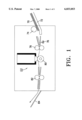
- FIG. 1 is a schematic illustration of a typical ink-jet printer
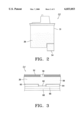
- FIG. 2 is a side view of a typical cartridge used in an ink-jet printer
- FIG. 3 is a cross sectional view of a typical head of an ink-jet printer cartridge
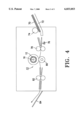
- FIG. 4 is a schematic illustration of an ink-jet printer using a drum cartridge constructed in accord with the preferred embodiment
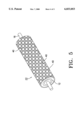
- FIG. 5 is a perspective view of the drum cartridge shown in FIG. 4;
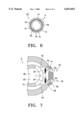
- FIG. 6 is a cross sectional view of the drum cartridge shown in FIG. 4.
- FIG. 7 is an exploded view of the area "A" FIG. 6.
- FIG. 1 illustrates a schematic view of the configuration of a typical ink-jet printer.
- the printer has a tray 72 that holds paper 70 and a paper feed roller 74, that is installed above the leading edge of the paper tray 72.
- the paper feed roller loads the paper into the printer.
- a sensor 76 is installed at one side of paper feed roller 74 to coordinate the paper feed roller 74 and the transfer roller 78.
- the transfer roller 78 is used to transfer the paper 70 to the ink cartridge 50 that contains the printing head unit 54 (FIG. 3).
- the ink cartridge undergoes a rectilinear reciprocating motion that is driven by a motor (not shown) installed beside transfer roller 78.
- the platen roller 80 is installed below the ink cartridge 50 and continues to transfer the paper 70 while the printing head is printing on it.
- the paper discharge roller 82 discharges the printed paper to stacker 84.
- cartridge 50 consists of an ink container 51, which stores the ink 38, and a head 54.
- FIG. 3 illustrates the configuration of the printing head 54.
- the ink 38 is ejected from the ejection orifice 56 that is located in the printing head plate 52.
- a reservoir 58 in the printing head provides ink 38 to the ejection orifice.
- a resistive heating element 62 is installed in the bottom of the ink reservoir 58 that heats and evaporates the ink 38 to create vapor pressure inside the reservoir.
- Electrodes 64 are installed on both sides of the heating element 62 thereby supplying energy to the heating element.
- Substrate layer 68 is made of silicon.
- a resistor layer 66 insulates the electrodes 64 and is installed below the electrodes 64.
- a protective film 60 formed on the electrodes 68, protects the electrodes 64, the heating element 62, and the resistor layer 66 from corrosion and oxidation reactions with the ink.
- the operation of the ink-jet printer with a cartridge that follows a rectilinear reciprocating motion during printing is as follows. Once the printer is switched "on" paper 70 from the paper tray 72 is transported by the paper feed roller 74. The paper feed roller 74 stops after a specified period of time depending on its distance from the transfer roller 78. The paper is then fed to the printer cartridge 50 by the transfer roller 78. The printing head 54 prints on the paper while the paper is being transported past the cartridge. Once the control unit sends a print command to printer head 54, a voltage is applied to electrodes 64. Heating element 62 is given energy from the electrodes 64 and the heating element then evaporates the nearby ink and creates a gas bubble in the reservoir.
- Ink in the reservoir 58 is propelled by vapor pressure and sprayed onto the paper through the ejection orifice 56, thus forming the desired letters or pictures.
- Platen roller 80 fixes the image to the paper using a voltage between 500 and 5000 V. The paper is then transferred to a paper receiving tray 84 by the paper discharge roller 82.
- the typical ink-jet printer head 54 is installed in a serial matrix configuration that prints using a rectilinear reciprocating motion. Controlling the reciprocating motor to maintain resolution exceeding 300 dots per inch (dpi) requires complex technology as well as a mechanism to guide the rectilinear reciprocating motion of head 54. Serial printer heads following a rectilinear reciprocating motion are also limited in their printing speed. Special mechanisms can be installed to increase their printing speed, but this makes the printers very large and bulky.
- FIG. 4 shows an ink-jet printer using the a drum cartridge constructed according to the preferred embodiment.
- the drum cartridge 10 rotates on a shaft 16 and is installed beside the transfer roller 78.
- the platen roller 80 is installed under the drum cartridge 10 to fix the toner image to the paper using a large voltage.
- the surface of the drum cartridge 10 has multiple printing heads 40 that print images onto paper in accordance with electric signals sent from the control unit.
- One or more lines of printer heads 40 can be arranged in a spiral, or oblique helix formation on the cartridge, thus creating a checker pattern.
- a single printing head 40 may consist of a nozzle-plate with ejection orifices for ejecting ink onto paper; a reservoir for storing ink inside the printing head; a resistive element that heats the ink in the head and creates vapor pressure; first and second electrodes that provide energy to the resistive element; a slot for drawing the ink from the ink storage chamber in the cartridge into the reservoir in the printing head.
- the printing head's 40 nozzle plate 14 has ejection orifices 30 for ejecting bubbles 34 of ink from the reservoir 38 onto a sheet of paper.
- ejection orifices 30 can be used in each nozzle plate 10 to increase the print speed.
- Resistive heating elements 24 are installed along one edge of the reservoir 36 to create vapor pressure and gas bubbles 34 by heating the ink 38.
- First and second electrodes 22 and 26 are installed on both sides of each resistive heating element 24 to provide in a voltage to them.
- the slot 28 between resistor portions 24 draws ink 38 from the ink storage chamber in the cartridge toward the parts of the reservoir 36 where the resistor units 24 are installed.
- the first and second electrodes, 22 and 26, and the resistive heating elements 24 are installed on a substrate layer 12, which is made of silicon. A chamber 20 is created inside the substrate layer 12.
- the operation of the ink-jet printer with the drum cartridge having such is as follows Paper 70 from the paper tray 72 is loaded into the printer by the paper feed roller 74. The paper is then transferred to the drum cartridge 10 by the transfer roller 78. The drum cartridge 10 starts printing on the paper while rotating in a specified direction.
- the control unit sends a print command to a head 40, its first and second electrodes 22 and 26 are given a voltage that results in the resistive elements generating heat.
- ink 38 stored in the ink storage chamber 20 in the cartridge flows into the reservoir 36 through the slot 28 between the sets of electrodes.
- the ink 38 near the resistive heating elements 24 is evaporated and forms gaseous bubbles 34 that cause ink droplets to be ejected ejected, through the ejection orifices 30, onto a sheet of paper in the form of dots 32, thus forming letters or pictures.
- the platen roller 80 in FIG. 4 fixes the image to the paper with a voltage between 500 and 5000 V.
- the printed paper is transferred to paper receiving tray 84 by paper discharge roller 82.
- the ink-jet printer with a drum cartridge produces images having a resolution exceeding 300 dpi because the printing heads are installed in a rotating drum cartridge instead of on a cartridge that follows a reciprocating rectilinear motion.
- the drum cartridge increases the print speed to between 5 ppM and 20 ppM by using two or more ejection orifices in each printing head of the drum cartridge. Since the drum cartridge does not require a moving carriage to allow for rectilinear motion, the printer can also be miniaturized.
Abstract
Description
Claims (28)
Applications Claiming Priority (2)
| Application Number | Priority Date | Filing Date | Title |
|---|---|---|---|
| KR96-40651 | 1996-09-18 | ||
| KR1019960040651A KR100208378B1 (en) | 1996-09-18 | 1996-09-18 | Ink-jet printer apparatus of a drum type head |
Publications (1)
| Publication Number | Publication Date |
|---|---|
| US6033053A true US6033053A (en) | 2000-03-07 |
Family
ID=19474255
Family Applications (1)
| Application Number | Title | Priority Date | Filing Date |
|---|---|---|---|
| US08/933,337 Expired - Fee Related US6033053A (en) | 1996-09-18 | 1997-09-18 | Ink-jet printer with a drum cartridge having a plurality of heads |
Country Status (5)
| Country | Link |
|---|---|
| US (1) | US6033053A (en) |
| EP (1) | EP0830944B1 (en) |
| JP (1) | JPH10100449A (en) |
| KR (1) | KR100208378B1 (en) |
| DE (1) | DE69723637T2 (en) |
Cited By (8)
| Publication number | Priority date | Publication date | Assignee | Title |
|---|---|---|---|---|
| US20040081689A1 (en) * | 2002-10-24 | 2004-04-29 | Dunfield John Stephen | Pharmaceutical dosage form and method of making |
| US6786591B2 (en) * | 2002-10-24 | 2004-09-07 | Hewlett-Packard Development Company, L.P. | Fluid ejector apparatus and methods |
| US20050157003A1 (en) * | 2004-01-21 | 2005-07-21 | Silverbrook Research Pty Ltd | Method for facilitating the upgrade of an inkjet printer |
| US7059698B1 (en) | 2002-10-04 | 2006-06-13 | Lexmark International, Inc. | Method of altering an effective print resolution of an ink jet printer |
| US20060164461A1 (en) * | 2005-01-21 | 2006-07-27 | Xerox Corporation | Ink jet printhead having two dimensional shuttle architecture |
| US20090145511A1 (en) * | 2006-01-10 | 2009-06-11 | Volker Till | Method of printing a pictorial image onto the circumferential outer surface of beverage bottles and filling beverage bottles in a bottling plant for filling bottles with a liquid beverage filling material in rotary filling machinery and apparatus therefor |
| US20100033534A1 (en) * | 2008-08-06 | 2010-02-11 | Mccoy Donald Paul | Rotary inkjet imaging apparatus and method for printing on a stationary page of media in a curved configuration |
| US20100165043A1 (en) * | 2008-12-31 | 2010-07-01 | Mccoy Donald Paul | Rotary Printhead Disc In A Rotary Inkjet Imaging Apparatus |
Families Citing this family (5)
| Publication number | Priority date | Publication date | Assignee | Title |
|---|---|---|---|---|
| US7922299B2 (en) | 2003-07-31 | 2011-04-12 | Moshe Einat | Ink jet printing method and apparatus |
| JP2009202434A (en) | 2008-02-28 | 2009-09-10 | Seiko Epson Corp | Fluid jetting apparatus |
| KR100953495B1 (en) * | 2008-05-21 | 2010-04-16 | 건국대학교 산학협력단 | Method and Apparatus for Roll-To-Roll type Printing |
| JP6877097B2 (en) * | 2016-06-28 | 2021-05-26 | 昭和アルミニウム缶株式会社 | Manufacturing method for printing equipment and beverage cans |
| KR20200058797A (en) | 2018-11-20 | 2020-05-28 | 현대자동차주식회사 | Oil pan drain device for vehicle |
Citations (18)
| Publication number | Priority date | Publication date | Assignee | Title |
|---|---|---|---|---|
| US3640214A (en) * | 1968-06-21 | 1972-02-08 | Precisa Ag | Selective printer employing inking spark discharge |
| JPS60972A (en) * | 1983-06-08 | 1985-01-07 | Nozaki Insatsu Shigyo Kk | Thermal head |
| US4555717A (en) * | 1982-06-16 | 1985-11-26 | Matsushita Electric Industrial Company, Limited | Ink jet printing head utilizing pressure and potential gradients |
| US4580148A (en) * | 1985-02-19 | 1986-04-01 | Xerox Corporation | Thermal ink jet printer with droplet ejection by bubble collapse |
| US4714936A (en) * | 1985-06-24 | 1987-12-22 | Howtek, Inc. | Ink jet printer |
| US4769654A (en) * | 1982-09-01 | 1988-09-06 | Konishiroku Photo Industry Co., Ltd. | Ink jet printing head having plurality of ink-jetting units disposed parallel to circular-shaped reference plane |
| US4785311A (en) * | 1986-01-30 | 1988-11-15 | Canon Kabushiki Kaisha | Recording head apparatus and method having pluralities of crossed electrodes |
| US4855768A (en) * | 1987-03-31 | 1989-08-08 | Minolta Camera Kabushiki Kaisha | Digital printing apparatus |
| JPH05124182A (en) * | 1991-11-01 | 1993-05-21 | Canon Inc | Ink-jet recorder |
| JPH05147284A (en) * | 1991-11-30 | 1993-06-15 | Mita Ind Co Ltd | Ink jet recording apparatus |
| EP0556045A2 (en) * | 1992-02-12 | 1993-08-18 | Canon Kabushiki Kaisha | Image recording apparatus with improved conveying system for recording medium |
| JPH05261906A (en) * | 1992-03-19 | 1993-10-12 | Fujitsu Ltd | Rotating ink jet head |
| EP0600712A2 (en) * | 1992-11-30 | 1994-06-08 | Hewlett-Packard Company | Method and apparatus for ink transfer printing |
| US5322594A (en) * | 1993-07-20 | 1994-06-21 | Xerox Corporation | Manufacture of a one piece full width ink jet printing bar |
| WO1995029063A1 (en) * | 1994-04-20 | 1995-11-02 | OCé PRINTING SYSTEMS GMBH | Thermoelectric printing unit for transferring ink to a print carrier |
| US5465108A (en) * | 1991-06-21 | 1995-11-07 | Rohm Co., Ltd. | Ink jet print head and ink jet printer |
| US5509058A (en) * | 1992-09-11 | 1996-04-16 | Mitel Corporation | Global management of telephone directory |
| US5552812A (en) * | 1986-12-10 | 1996-09-03 | Canon Kabushiki Kaisha | Recording apparatus having an ink mist evacuation system |
-
1996
- 1996-09-18 KR KR1019960040651A patent/KR100208378B1/en not_active IP Right Cessation
-
1997
- 1997-09-18 DE DE69723637T patent/DE69723637T2/en not_active Expired - Fee Related
- 1997-09-18 JP JP9253994A patent/JPH10100449A/en active Pending
- 1997-09-18 US US08/933,337 patent/US6033053A/en not_active Expired - Fee Related
- 1997-09-18 EP EP97307268A patent/EP0830944B1/en not_active Expired - Lifetime
Patent Citations (19)
| Publication number | Priority date | Publication date | Assignee | Title |
|---|---|---|---|---|
| US3640214A (en) * | 1968-06-21 | 1972-02-08 | Precisa Ag | Selective printer employing inking spark discharge |
| US4555717A (en) * | 1982-06-16 | 1985-11-26 | Matsushita Electric Industrial Company, Limited | Ink jet printing head utilizing pressure and potential gradients |
| US4769654A (en) * | 1982-09-01 | 1988-09-06 | Konishiroku Photo Industry Co., Ltd. | Ink jet printing head having plurality of ink-jetting units disposed parallel to circular-shaped reference plane |
| JPS60972A (en) * | 1983-06-08 | 1985-01-07 | Nozaki Insatsu Shigyo Kk | Thermal head |
| US4580148A (en) * | 1985-02-19 | 1986-04-01 | Xerox Corporation | Thermal ink jet printer with droplet ejection by bubble collapse |
| US4714936A (en) * | 1985-06-24 | 1987-12-22 | Howtek, Inc. | Ink jet printer |
| US4785311A (en) * | 1986-01-30 | 1988-11-15 | Canon Kabushiki Kaisha | Recording head apparatus and method having pluralities of crossed electrodes |
| US5552812A (en) * | 1986-12-10 | 1996-09-03 | Canon Kabushiki Kaisha | Recording apparatus having an ink mist evacuation system |
| US4855768A (en) * | 1987-03-31 | 1989-08-08 | Minolta Camera Kabushiki Kaisha | Digital printing apparatus |
| US5465108A (en) * | 1991-06-21 | 1995-11-07 | Rohm Co., Ltd. | Ink jet print head and ink jet printer |
| JPH05124182A (en) * | 1991-11-01 | 1993-05-21 | Canon Inc | Ink-jet recorder |
| JPH05147284A (en) * | 1991-11-30 | 1993-06-15 | Mita Ind Co Ltd | Ink jet recording apparatus |
| EP0556045A2 (en) * | 1992-02-12 | 1993-08-18 | Canon Kabushiki Kaisha | Image recording apparatus with improved conveying system for recording medium |
| JPH05261906A (en) * | 1992-03-19 | 1993-10-12 | Fujitsu Ltd | Rotating ink jet head |
| US5509058A (en) * | 1992-09-11 | 1996-04-16 | Mitel Corporation | Global management of telephone directory |
| EP0600712A2 (en) * | 1992-11-30 | 1994-06-08 | Hewlett-Packard Company | Method and apparatus for ink transfer printing |
| US5322594A (en) * | 1993-07-20 | 1994-06-21 | Xerox Corporation | Manufacture of a one piece full width ink jet printing bar |
| WO1995029063A1 (en) * | 1994-04-20 | 1995-11-02 | OCé PRINTING SYSTEMS GMBH | Thermoelectric printing unit for transferring ink to a print carrier |
| US5760808A (en) * | 1994-04-20 | 1998-06-02 | Oce Printing Systems Gmbh | Thermoelectric printing unit for transferring an ink onto a recording medium |
Non-Patent Citations (6)
| Title |
|---|
| Patent Abstracts of Japan, vol. 009, No. 114 (M 380), May 18, 1985 & JP 60 000972 A (Nozaki Insatsu Shigyo KK), Jan. 7, 1985. * |
| Patent Abstracts of Japan, vol. 009, No. 114 (M-380), May 18, 1985 & JP 60 000972 A (Nozaki Insatsu Shigyo KK), Jan. 7, 1985. |
| Patent Abstracts of Japan, vol. 017, No. 537 (M 1487), & JP 05 147284 A (Mita Ind Co Ltd), Jun. 15, 1993. * |
| Patent Abstracts of Japan, vol. 017, No. 537 (M-1487), & JP 05 147284 A (Mita Ind Co Ltd), Jun. 15, 1993. |
| Patent Abstracts of Japan, vol. 018, No. 025 (M 1542), Jan. 14, 1994 & JP 05 261906 (Fujitsu Ltd.) Oct. 12, 1993. * |
| Patent Abstracts of Japan, vol. 018, No. 025 (M-1542), Jan. 14, 1994 & JP 05 261906 (Fujitsu Ltd.) Oct. 12, 1993. |
Cited By (15)
| Publication number | Priority date | Publication date | Assignee | Title |
|---|---|---|---|---|
| US7059698B1 (en) | 2002-10-04 | 2006-06-13 | Lexmark International, Inc. | Method of altering an effective print resolution of an ink jet printer |
| US6786591B2 (en) * | 2002-10-24 | 2004-09-07 | Hewlett-Packard Development Company, L.P. | Fluid ejector apparatus and methods |
| US20040241008A1 (en) * | 2002-10-24 | 2004-12-02 | Dunfield John Stephen | Fluid ejector apparatus and methods |
| US20040081689A1 (en) * | 2002-10-24 | 2004-04-29 | Dunfield John Stephen | Pharmaceutical dosage form and method of making |
| US7547092B2 (en) * | 2004-01-21 | 2009-06-16 | Silverbrook Research Pty Ltd | Method for facilitating the upgrade of an inkjet printer |
| US20050157003A1 (en) * | 2004-01-21 | 2005-07-21 | Silverbrook Research Pty Ltd | Method for facilitating the upgrade of an inkjet printer |
| US7862136B2 (en) | 2004-01-21 | 2011-01-04 | Silverbrook Research Pty Ltd | Inkjet printer system with interchangeable printhead cartridges and cradles |
| US7240985B2 (en) | 2005-01-21 | 2007-07-10 | Xerox Corporation | Ink jet printhead having two dimensional shuttle architecture |
| US20060164461A1 (en) * | 2005-01-21 | 2006-07-27 | Xerox Corporation | Ink jet printhead having two dimensional shuttle architecture |
| US20090145511A1 (en) * | 2006-01-10 | 2009-06-11 | Volker Till | Method of printing a pictorial image onto the circumferential outer surface of beverage bottles and filling beverage bottles in a bottling plant for filling bottles with a liquid beverage filling material in rotary filling machinery and apparatus therefor |
| US9221275B2 (en) * | 2006-01-10 | 2015-12-29 | Khs Gmbh | Method of printing a pictorial image onto the circumferential outer surface of beverage bottles and filling beverage bottles in a bottling plant for filling bottles with a liquid beverage filling material in rotary filling machinery and apparatus therefor |
| US20100033534A1 (en) * | 2008-08-06 | 2010-02-11 | Mccoy Donald Paul | Rotary inkjet imaging apparatus and method for printing on a stationary page of media in a curved configuration |
| US8001893B2 (en) * | 2008-08-06 | 2011-08-23 | Lexmark International, Inc. | Rotary inkjet imaging apparatus and method for printing on a stationary page of media in a curved configuration |
| US20100165043A1 (en) * | 2008-12-31 | 2010-07-01 | Mccoy Donald Paul | Rotary Printhead Disc In A Rotary Inkjet Imaging Apparatus |
| US8162438B2 (en) * | 2008-12-31 | 2012-04-24 | Lexmark International, Inc. | Rotary printhead disc in a rotary inkjet imaging apparatus |
Also Published As
| Publication number | Publication date |
|---|---|
| JPH10100449A (en) | 1998-04-21 |
| KR19980021706A (en) | 1998-06-25 |
| DE69723637T2 (en) | 2004-04-15 |
| DE69723637D1 (en) | 2003-08-28 |
| EP0830944A2 (en) | 1998-03-25 |
| EP0830944B1 (en) | 2003-07-23 |
| KR100208378B1 (en) | 1999-07-15 |
| EP0830944A3 (en) | 1999-03-03 |
Similar Documents
| Publication | Publication Date | Title |
|---|---|---|
| US6234605B1 (en) | Multiple resolution pagewidth ink jet printer including a positionable pagewidth printbear | |
| JP4820045B2 (en) | Inkjet printhead having four staggered rows of nozzles | |
| US6033053A (en) | Ink-jet printer with a drum cartridge having a plurality of heads | |
| US6428144B2 (en) | Ink jet recording head and inkjet recording apparatus | |
| US6048059A (en) | Variable power preheater for an ink printer | |
| JP2004148829A (en) | Fluid jet device and method of distributing fluid | |
| US6966627B2 (en) | Printhead orientation | |
| US6217147B1 (en) | Printer having media advance coordinated with primitive size | |
| EP1270225B1 (en) | A system and method for using lower data rates for printheads with closely spaced nozzles | |
| EP1057647B1 (en) | Ink jet printer | |
| CA2260382C (en) | Drum platen type printing machine for printing on regular and card-stock substrates | |
| JP7084983B2 (en) | Liquid discharge head and recording device | |
| US7909434B2 (en) | Printhead and method of printing | |
| US20090244147A1 (en) | Ink jet recording apparatus | |
| US6328413B1 (en) | Inkjet printer spitting method for reducing print cartridge cross-contamination | |
| JP2001347663A (en) | Ink jet recording head and ink jet recorder | |
| US6812953B2 (en) | System for reducing the effect of aerodynamic induced errors in a drop-on-demand printing system | |
| JP3233368B2 (en) | Recording device | |
| JPH04216055A (en) | Ink jet recording apparatus | |
| JPH054335A (en) | Recording device | |
| JPH11254665A (en) | Liquid ink marking engine | |
| US11155082B2 (en) | Fluid ejection die | |
| JPH0441242A (en) | Ink jet recorder | |
| JP2932878B2 (en) | Ink jet recording device | |
| JPH07276726A (en) | Ink-jet recording device |
Legal Events
| Date | Code | Title | Description |
|---|---|---|---|
| AS | Assignment |
Owner name: SAMSUNG ELECTRONICS CO., LTD., KOREA, REPUBLIC OF Free format text: ASSIGNMENT OF ASSIGNORS INTEREST;ASSIGNOR:EUN, JONG-MOON;REEL/FRAME:008760/0258 Effective date: 19971012 |
|
| AS | Assignment |
Owner name: SAMSUNG ELECTRONICS CO., LTD., KOREA, REPUBLIC OF Free format text: ASSIGNMENT OF ASSIGNORS INTEREST;ASSIGNOR:KIM, HO-GI;REEL/FRAME:008867/0005 Effective date: 19971204 |
|
| FEPP | Fee payment procedure |
Free format text: PAYOR NUMBER ASSIGNED (ORIGINAL EVENT CODE: ASPN); ENTITY STATUS OF PATENT OWNER: LARGE ENTITY |
|
| FPAY | Fee payment |
Year of fee payment: 4 |
|
| FPAY | Fee payment |
Year of fee payment: 8 |
|
| REMI | Maintenance fee reminder mailed | ||
| LAPS | Lapse for failure to pay maintenance fees | ||
| STCH | Information on status: patent discontinuation |
Free format text: PATENT EXPIRED DUE TO NONPAYMENT OF MAINTENANCE FEES UNDER 37 CFR 1.362 |
|
| FP | Lapsed due to failure to pay maintenance fee |
Effective date: 20120307 |