US6033240A - Retractable media jack operable with two discrete media connectors - Google Patents
Retractable media jack operable with two discrete media connectors Download PDFInfo
- Publication number
- US6033240A US6033240A US09/183,839 US18383998A US6033240A US 6033240 A US6033240 A US 6033240A US 18383998 A US18383998 A US 18383998A US 6033240 A US6033240 A US 6033240A
- Authority
- US
- United States
- Prior art keywords
- plate
- media
- contact
- socket
- electrical
- Prior art date
- Legal status (The legal status is an assumption and is not a legal conclusion. Google has not performed a legal analysis and makes no representation as to the accuracy of the status listed.)
- Expired - Lifetime
Links
Images


Classifications
-
- H—ELECTRICITY
- H01—ELECTRIC ELEMENTS
- H01R—ELECTRICALLY-CONDUCTIVE CONNECTIONS; STRUCTURAL ASSOCIATIONS OF A PLURALITY OF MUTUALLY-INSULATED ELECTRICAL CONNECTING ELEMENTS; COUPLING DEVICES; CURRENT COLLECTORS
- H01R31/00—Coupling parts supported only by co-operation with counterpart
- H01R31/005—Intermediate parts for distributing signals
-
- H—ELECTRICITY
- H01—ELECTRIC ELEMENTS
- H01R—ELECTRICALLY-CONDUCTIVE CONNECTIONS; STRUCTURAL ASSOCIATIONS OF A PLURALITY OF MUTUALLY-INSULATED ELECTRICAL CONNECTING ELEMENTS; COUPLING DEVICES; CURRENT COLLECTORS
- H01R2201/00—Connectors or connections adapted for particular applications
- H01R2201/06—Connectors or connections adapted for particular applications for computer periphery
-
- H—ELECTRICITY
- H01—ELECTRIC ELEMENTS
- H01R—ELECTRICALLY-CONDUCTIVE CONNECTIONS; STRUCTURAL ASSOCIATIONS OF A PLURALITY OF MUTUALLY-INSULATED ELECTRICAL CONNECTING ELEMENTS; COUPLING DEVICES; CURRENT COLLECTORS
- H01R24/00—Two-part coupling devices, or either of their cooperating parts, characterised by their overall structure
- H01R24/60—Contacts spaced along planar side wall transverse to longitudinal axis of engagement
- H01R24/62—Sliding engagements with one side only, e.g. modular jack coupling devices
-
- H—ELECTRICITY
- H01—ELECTRIC ELEMENTS
- H01R—ELECTRICALLY-CONDUCTIVE CONNECTIONS; STRUCTURAL ASSOCIATIONS OF A PLURALITY OF MUTUALLY-INSULATED ELECTRICAL CONNECTING ELEMENTS; COUPLING DEVICES; CURRENT COLLECTORS
- H01R27/00—Coupling parts adapted for co-operation with two or more dissimilar counterparts
-
- Y—GENERAL TAGGING OF NEW TECHNOLOGICAL DEVELOPMENTS; GENERAL TAGGING OF CROSS-SECTIONAL TECHNOLOGIES SPANNING OVER SEVERAL SECTIONS OF THE IPC; TECHNICAL SUBJECTS COVERED BY FORMER USPC CROSS-REFERENCE ART COLLECTIONS [XRACs] AND DIGESTS
- Y10—TECHNICAL SUBJECTS COVERED BY FORMER USPC
- Y10S—TECHNICAL SUBJECTS COVERED BY FORMER USPC CROSS-REFERENCE ART COLLECTIONS [XRACs] AND DIGESTS
- Y10S439/00—Electrical connectors
- Y10S439/946—Memory card cartridge
Definitions
- the present invention relates to electrical receptacles and, more specifically, discrete media jacks that are configured to physically receive and electrically couple with two media connectors such as an RJ type connector and a PC card type connector.
- An electrical coupler includes a connector or plug and a corresponding jack.
- the jack typically includes an aperture or socket configured to receive the connector so as to establish electrical communication therebetween.
- a PC card is a small thin card typically having a standard size.
- a connector formed at one end is configured to couple with the electrical apparatus.
- a jack is formed at the opposing end of the PC card is configured to couple with a desired outside line such as a telephone line or a network line.
- Disposed within the PC card is a circuit board providing the necessary circuitry to perform one or more intended functions.
- the circuit board comprises a modem which enables the electrical apparatus to receive and transmit information over telephone lines.
- the circuit board enables the electrical apparatus to receive and transmit information with a network system over a network cable.
- One conventional type of jack used for connecting a PC card to an exterior line comprises a thin plate which is retractable within the PC card.
- the plate has a top surface with an aperture formed therein.
- the aperture is configured to receive an RJ type connector such as an RJ-11, commonly referred to as a telephone plug.
- Another conventional type of coupler used for connecting a PC card to an exterior line comprises a low profile PC card connector.
- the PC card connector includes a long thin plug.
- a corresponding jack is formed on the PC card and includes a long thin socket configured to receive the plug.
- RJ type connectors and PC card type connectors have unique benefits and are used extensively in the electrical field. Unfortunately, they are not interchangeable in that an RJ connector cannot be inserted into a jack for a PC card connector. Accordingly, adapters are required to facilitate electrical communication between the different connector and jack configurations. Such adapters, however, complicate the connection process and are often lost or misplaced. Furthermore, due to space and size limitations, positioning two or more different types of jacks side by side on a PC card is impractical or at least a loss of valuable space.
- Another object of the present invention is to provide a media jack as above which minimizes the required space.
- Yet another object is to provide the above media jack which eliminates the need for using an adapter with either the first or second media connector.
- the media jack comprises a plate that can be selectively retracted into an opening of a PC card or other electrical apparatus.
- the plate has a substantially L-shaped side view which includes a thin elongated body portion having an enlarged head portion formed on the end thereof. Extending through the body portion is an aperture. Projecting from the body portion into the aperture are a plurality of contact wires.
- the aperture is configured to receive an RJ type connector so that the RJ connector is in electrical communication with the contact wires.
- the enlarged head portion has a front face and an opposing back face.
- the back face of the head portion is positioned below the body portion.
- Recessed within the front face is a front socket having a plurality of discrete contacts formed therein.
- the front socket is configured to received a PC card type connector so that the contacts are in electrical communication therewith.
- Recessed within the back face of the head portion is a slot having a plurality of discrete female contacts. Individual electrical lines extend from each of the contacts in the front socket to corresponding female contacts in the slot.
- each male contact engages a corresponding female contact on the head portion to effect electrical communication therewith. Accordingly, when the plate is in the retracted position, the contacts within the front socket are in electrical communication with the male contacts within the opening.
- the inventive media jack has a variety of unique advantages over the present state of the art. Specifically, since the inventive media jack can couple with both an RJ type connector and a PC card type connector, no adapters are required. Furthermore, by having the aperture and socket formed on a single retractable plate, minimal space is occupied by the inventive media jack. Specifically, the inventive media jack occupies less space than if separate media jacks were placed side by side on the PC card.
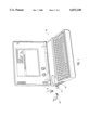
- FIG. 1 is a perspective view of a PC card inserted within a computer, the PC card having an inventive media jack configured to receive an RJ type connector and a PC card type connector;
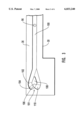
- FIG. 2 is a partially cut away top view of the PC card shown in FIG. 1 having the inventive media jack projecting therefrom;
- FIG. 3 is an elevated side view of the media jack shown in FIG. 2;
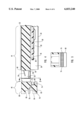
- FIG. 4 is a cross-sectional side view of the media jack shown in FIG. 2 in an extended position
- FIG. 5 is a cross sectional view of the media jack shown in FIG. 4 taken along section line 5--5;
- FIG. 6 is a cross sectional side view of the media jack shown in FIG. 4 in a retracted position
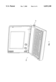
- FIG. 7 is a perspective view of a computer having the inventive media jack shown in FIG. 1 directly mounted thereon.
- PC card Depicted in FIG. 1 is a computer 10 housing a PC card 12.
- PC card is broadly intended to include the various types of cards falling within the Personal Computer Memory Card Internationals Association (PCMCIA) parameters, communication cards falling outside of those standards, and cards which are developed under new standards. Examples of PC cards include modem cards, network cards, memory cards, SCSI cards, cellular phone cards, and combinations thereof. Although not required, such PC cards can have a Type I, II, or III form factor.
- PCMCIA Personal Computer Memory Card Internationals Association
- media jack 14 is configured to physically and electrically couple with a first media connector 16 and a second media connector 18.
- media connector is broadly intended to include connectors and plugs both currently known and those developed in the future which can be used to establish an electrical coupling for transferring electrical signals.
- media connectors include RJ type connectors such as an RJ-11, RJ-45, or other RJ-type connector and PC card type connectors.
- Examples of PC card type connectors are those connectors which fall under the specification of PCMCIA Specific Extensions found in the PCMCIA/JEIDA PC Card Standard.
- Other media connectors include D connectors, circular connectors, and ISB connectors.
- first media plug 16 is depicted as an RJ-45 and second media plug 18 is depicted as a fifteen pin PC card connector.
- PC card 12 comprises a housing 19 which includes a top cover plate 22, an opposing bottom cover plate 24, and a narrow border member 23 securing plates 22 and 24 together around the perimeter thereof. Positioned between cover plates 22 and 24 is a circuit board 20. Formed at a front end 26 of PC card 12 is an opening 28 extending through border member 23. Media jack 14 is slidably positioned within opening 28 over a portion of circuit board 20. Media Jack 14 is selectively movable between an extended position as shown in FIG. 2 and a retracted position as shown in FIG. 6.
- Media jack 14 comprises an elongated plate 30 having a first side 32 with a stop 34 projecting at the end thereof and an opposing second side 36.
- means are provided for biasing plate 30 outward into the extended position.
- formed at the end of side 36 is a tail 38.
- Tail 38 is slidably mounted on a rail 40 and has an opening 41 configured to receive a spring 42.
- the opposing end of spring 42 is mounted on a post 43.
- spring 42 functions to bias plate 30 outward into the extended position.
- spring 42 can be placed at different locations to bias against plate 30.
- spring 42 can be replaced with other conventional types of springs such as a leaf spring.
- the present invention also includes means for selectively retaining plate 30 in the retracted position.
- a channel 100 is recessed within second side 36 of plate 30.
- a substantially heart shaped ratcheted groove 101 is formed at the end of channel 100.
- Disposed within channel 100 is a small wire actuating arm 96 which is held in position by a spring 98.
- actuating arm 96 travels along channel 100 to ratcheted groove 101.
- actuating arm 96 travels up a first ramp 102 and then drops into a first step 104.
- spring 42 produces a biasing outward force on plate 30 causing actuating arm 96 to drop into a second step 106 and bias against a brace 108.
- actuating arm 96 prevents plate 30, which is continually urged by spring 42, from automatically advancing out into the extended position.
- plate 30 is manually pushed slightly into housing 24 causing actuating arm 96 to drop onto a third step 110.
- actuating arm 96 slides within a descending ramp 112 and back into channel 100, thereby allowing plate 30 to freely slide outward into the extended position.
- the above process can be repeated to selectively move plate 30 between the retracted and extended position.
- Alternative embodiments of the means for selectively retaining are disclosed in the '401 patent and '819 application which were previously incorporated herein by specific reference.
- plate 30 has a substantially L-shaped side view which comprises a substantially flat body portion 44 having a head portion 46 formed on the front end thereof.
- Body portion 44 has a substantially flat top surface 48 and an opposing flat bottom surface 50.
- means are provided for electrically coupling first media connector 16 with circuit board 20 when plate 30 is in the extended position.
- extending between top surface 48 and bottom surface 50 of body portion 44 is an aperture 52.
- Projecting into aperture 52 are plurality of contact wires 54.
- Each of contact wires 54 electrically communicate with circuit board 20 through a flexible wire ribbon 56.
- Rotatably mounted within aperture 52 is a U-shaped harness 58.
- Aperture 52 is configured to receive first media connector 16 such that contact wires 54 electrically communication with first media connector 16. Harness 58 functions as a stop to prevent first media connector 16 from passing through aperture 52.
- An aperture 52 configured to electrically couple with an first media connector 16 is found on the XJack® manufactured by 3Com out of Salt Lake City, Utah.
- Alternative examples of different structures configured to receive first media connector 16 for electrically coupling with circuit board 20 are disclosed in the '401 patent and '819 application which were previously incorporated herein by specific reference.
- the present invention also includes means for electrically coupling second media connector 18 with circuit board 20 when plate 30 is in the retracted position.
- head portion 46 comprises a top surface 60 that is flush with top surface 48 of body portion 44 and an opposing bottom surface 62 which extends below bottom surface 50 of body portion 44.
- Head portion 46 also includes a front face 64 and an opposing back face 66.
- Back face 66 extends from bottom surface 62 of head portion 46 to bottom surface 50 of body portion 44.
- Formed within front face 64 is a front socket 68 having a plurality of discrete contact pins 70 projecting therein. Socket 68 is configured to physically receive second media connector 18 such that contact pins 70 are in electrical communication therewith.
- socket 68 can have substantially the same configuration as conventional sockets used for PC card type connectors.
- the present invention also provides means for electrically coupling contact pins 70 with circuit board 20 when plate 30 is in its retracted position.
- a slot 72 is recessed within back face 66 of head portion 46. Disposed within slot 72 are a plurality of spaced apart female contacts 74. Each female contact 74 electrically communications with a corresponding contact pin 70 by a line 76.
- circuit board 20 has a front end 78 having a plurality of male contacts 80 formed thereon.
- Male contacts 80 electrically communicate with desired circuitry on circuit board 20.
- front end 78 of circuit board 20 is received within slot 72 such that each male contact 80 electrically communicates with a corresponding female contact 74, thereby effecting electrical communication between contact pins 70 and circuit board 20.
- a small gap 82 is formed between the base of female contact 74 and the lead face of male contact 80. Gap 82 enables plate 30 to be pushed slightly further into opening 28 for allowing plate 30 to subsequently extend outward as previously discussed with regard to the means for retaining plate 30 into the retracted position.
- aperture 52 when plate 30 is in the extended position, aperture 52 is openly exposed for receiving first media connector 16 in electrical communication with circuit board 20. In this extended position, however, female contacts 74 are separated from male contacts 80. Accordingly, contact pins 70 within socket 68 is not in electrical communication with circuit board 20.
- aperture 52 When plate 30 is in the retracted position, aperture 52 is disposed within housing 19 so that first media connector 16 cannot be received therein. Socket 68, however, can now receive second media connector 18 in electrical communication with circuit board 20.
- the present invention also envisions a plurality of different embodiments which provide the means for electrically coupling contact pins 70 with circuit board 20 when plate 30 is in its retracted position.
- contacts 74 and 80 can be replaced with a connector and socket configuration such as that used with PC card type connectors or RJ type connectors.
- contacts 74 and 80 can be replaced with a connector and socket configuration such as that used with PC card type connectors or RJ type connectors.
- flat contacts which only bias against a single surface can be used.
- circuit board 20 can be cut out around plate 20 to allow more room for media jack 14.
- a separate contact structure which is wired with circuit board 20 can then be positioned so as to electrically couple with female contacts 74 when plate 30 is in the retracted position.
- inventive media jack need not be incorporated into a PC card. Rather, the inventive media jack can be incorporated directly onto an electrical apparatus such as a laptop computer, PIM, cellular telephone or other electrical apparatus containing a CPU.
- inventive media jack 14 is mounted directly on a laptop computer 114 without the use of a PC card. Examples of how media jacks can be directly mounted to electrical apparatus are disclosed in the '819 application which was previously incorporated herein by specific reference.
Abstract
Description
Claims (18)
Priority Applications (1)
| Application Number | Priority Date | Filing Date | Title |
|---|---|---|---|
| US09/183,839 US6033240A (en) | 1998-10-30 | 1998-10-30 | Retractable media jack operable with two discrete media connectors |
Applications Claiming Priority (1)
| Application Number | Priority Date | Filing Date | Title |
|---|---|---|---|
| US09/183,839 US6033240A (en) | 1998-10-30 | 1998-10-30 | Retractable media jack operable with two discrete media connectors |
Publications (1)
| Publication Number | Publication Date |
|---|---|
| US6033240A true US6033240A (en) | 2000-03-07 |
Family
ID=22674509
Family Applications (1)
| Application Number | Title | Priority Date | Filing Date |
|---|---|---|---|
| US09/183,839 Expired - Lifetime US6033240A (en) | 1998-10-30 | 1998-10-30 | Retractable media jack operable with two discrete media connectors |
Country Status (1)
| Country | Link |
|---|---|
| US (1) | US6033240A (en) |
Cited By (17)
| Publication number | Priority date | Publication date | Assignee | Title |
|---|---|---|---|---|
| US6129566A (en) * | 1998-09-24 | 2000-10-10 | Ericsson Inc. | Compact connector socket assembly with fixed leads |
| US6325674B1 (en) | 2000-03-20 | 2001-12-04 | 3Com Corporation | Card edge connector for a modular jack |
| US6338656B1 (en) | 2000-03-20 | 2002-01-15 | 3Com Corporation | Modular jack for Type III PCMCIA cards |
| US6394850B1 (en) | 2000-03-20 | 2002-05-28 | David Oliphant | Contact pin design for a modular jack |
| US6419506B2 (en) * | 2000-01-20 | 2002-07-16 | 3Com Corporation | Combination miniature cable connector and antenna |
| US6447306B1 (en) | 2001-02-28 | 2002-09-10 | 3Com Corporation | PC card configuration |
| US6469681B2 (en) | 1999-10-12 | 2002-10-22 | 3Com Corporation | Removable antenna for connection to miniature modular jacks |
| US6475003B2 (en) * | 1999-10-12 | 2002-11-05 | 3Com Corporation | Physically independent connector for retractable and removeable extensions in thin-profile electronic devices |
| US6577500B2 (en) | 2001-02-28 | 2003-06-10 | 3Com Corporation | Wireless PC card |
| US6650546B2 (en) | 2001-02-27 | 2003-11-18 | 3Com Corporation | Chip component assembly |
| US20050157459A1 (en) * | 2004-01-15 | 2005-07-21 | Memphis-Zhihong Yin | Computer system with multiple-connector apparatus |
| US20130034973A1 (en) * | 2011-08-02 | 2013-02-07 | Compal Electronics, Inc. | Electronic device and connection port thereof |
| US20130163188A1 (en) * | 2011-12-26 | 2013-06-27 | Ping-Huei Lee | Electronic device |
| US20160104966A1 (en) * | 2014-10-09 | 2016-04-14 | Gbatteries Energy Inc. | Connectors for Delivery of Power |
| US10218200B2 (en) | 2012-03-25 | 2019-02-26 | Gbatteries Energy Canada Inc. | Systems and methods for enhancing the performance and utilization of battery systems |
| US10840725B2 (en) | 2016-07-10 | 2020-11-17 | Gbatteries Energy Canada Inc. | Battery charging with charging parameters sweep |
| US20220291722A1 (en) * | 2019-09-30 | 2022-09-15 | Hewlett-Packard Development Company, L.P. | Accessory docks with moveable holders |
Citations (5)
| Publication number | Priority date | Publication date | Assignee | Title |
|---|---|---|---|---|
| US5183404A (en) * | 1992-04-08 | 1993-02-02 | Megahertz Corporation | Systems for connection of physical/electrical media connectors to computer communications cards |
| US5547401A (en) * | 1992-04-08 | 1996-08-20 | Megahertz Corporation | Media connector interface for use with a thin-architecture communications card |
| US5773332A (en) * | 1993-11-12 | 1998-06-30 | Xircom, Inc. | Adaptable communications connectors |
| US5797771A (en) * | 1996-08-16 | 1998-08-25 | U.S. Robotics Mobile Communication Corp. | Cable connector |
| US5816832A (en) * | 1992-04-08 | 1998-10-06 | 3Com Corporation | Media connector interface for use with a PCMCIA-architecture communications card |
-
1998
- 1998-10-30 US US09/183,839 patent/US6033240A/en not_active Expired - Lifetime
Patent Citations (8)
| Publication number | Priority date | Publication date | Assignee | Title |
|---|---|---|---|---|
| US5183404A (en) * | 1992-04-08 | 1993-02-02 | Megahertz Corporation | Systems for connection of physical/electrical media connectors to computer communications cards |
| US5336099A (en) * | 1992-04-08 | 1994-08-09 | Megahertz Corporation | Media connector interface for use with a PCMCIA-architecture communications card |
| US5338210A (en) * | 1992-04-08 | 1994-08-16 | Megahertz Corporation | Media connector interface for use with a PCMCIA-architecture communications card |
| US5547401A (en) * | 1992-04-08 | 1996-08-20 | Megahertz Corporation | Media connector interface for use with a thin-architecture communications card |
| US5727972A (en) * | 1992-04-08 | 1998-03-17 | Aldous; Stephen C. | Media connector interface for use with a thin-architecture communications card |
| US5816832A (en) * | 1992-04-08 | 1998-10-06 | 3Com Corporation | Media connector interface for use with a PCMCIA-architecture communications card |
| US5773332A (en) * | 1993-11-12 | 1998-06-30 | Xircom, Inc. | Adaptable communications connectors |
| US5797771A (en) * | 1996-08-16 | 1998-08-25 | U.S. Robotics Mobile Communication Corp. | Cable connector |
Cited By (23)
| Publication number | Priority date | Publication date | Assignee | Title |
|---|---|---|---|---|
| US6129566A (en) * | 1998-09-24 | 2000-10-10 | Ericsson Inc. | Compact connector socket assembly with fixed leads |
| US6469681B2 (en) | 1999-10-12 | 2002-10-22 | 3Com Corporation | Removable antenna for connection to miniature modular jacks |
| US6475003B2 (en) * | 1999-10-12 | 2002-11-05 | 3Com Corporation | Physically independent connector for retractable and removeable extensions in thin-profile electronic devices |
| US6419506B2 (en) * | 2000-01-20 | 2002-07-16 | 3Com Corporation | Combination miniature cable connector and antenna |
| US6599152B1 (en) | 2000-03-20 | 2003-07-29 | 3Com Corporation | Contact pin design for a modular jack |
| US6325674B1 (en) | 2000-03-20 | 2001-12-04 | 3Com Corporation | Card edge connector for a modular jack |
| US6338656B1 (en) | 2000-03-20 | 2002-01-15 | 3Com Corporation | Modular jack for Type III PCMCIA cards |
| US6394850B1 (en) | 2000-03-20 | 2002-05-28 | David Oliphant | Contact pin design for a modular jack |
| US6488543B2 (en) | 2000-03-20 | 2002-12-03 | 3Com Corporation | Modular jack for type III PCMCIA cards |
| US6650546B2 (en) | 2001-02-27 | 2003-11-18 | 3Com Corporation | Chip component assembly |
| US6447306B1 (en) | 2001-02-28 | 2002-09-10 | 3Com Corporation | PC card configuration |
| US6577500B2 (en) | 2001-02-28 | 2003-06-10 | 3Com Corporation | Wireless PC card |
| US20050157459A1 (en) * | 2004-01-15 | 2005-07-21 | Memphis-Zhihong Yin | Computer system with multiple-connector apparatus |
| US7483262B2 (en) * | 2004-01-15 | 2009-01-27 | Hewlett-Packard Development Company, L.P. | Computer system with multiple-connector apparatus |
| US20130034973A1 (en) * | 2011-08-02 | 2013-02-07 | Compal Electronics, Inc. | Electronic device and connection port thereof |
| US20130163188A1 (en) * | 2011-12-26 | 2013-06-27 | Ping-Huei Lee | Electronic device |
| US10218200B2 (en) | 2012-03-25 | 2019-02-26 | Gbatteries Energy Canada Inc. | Systems and methods for enhancing the performance and utilization of battery systems |
| US11050281B2 (en) | 2012-03-25 | 2021-06-29 | Gbatteries Energy, Inc. | Systems and methods for enhancing the performance and utilization of battery systems |
| US20160104966A1 (en) * | 2014-10-09 | 2016-04-14 | Gbatteries Energy Inc. | Connectors for Delivery of Power |
| US10020608B2 (en) * | 2014-10-09 | 2018-07-10 | Gbatteries Energy Canada Inc. | Connectors for delivery of power |
| US10840725B2 (en) | 2016-07-10 | 2020-11-17 | Gbatteries Energy Canada Inc. | Battery charging with charging parameters sweep |
| US11362535B2 (en) | 2016-07-10 | 2022-06-14 | Gbatteries Energy Canada Inc. | Battery charging with charging parameters sweep |
| US20220291722A1 (en) * | 2019-09-30 | 2022-09-15 | Hewlett-Packard Development Company, L.P. | Accessory docks with moveable holders |
Similar Documents
| Publication | Publication Date | Title |
|---|---|---|
| US6033240A (en) | Retractable media jack operable with two discrete media connectors | |
| US5727972A (en) | Media connector interface for use with a thin-architecture communications card | |
| US5336099A (en) | Media connector interface for use with a PCMCIA-architecture communications card | |
| US6488542B2 (en) | Type III PCMCIA card with integrated receptacles for receiving standard communications plugs | |
| US5816832A (en) | Media connector interface for use with a PCMCIA-architecture communications card | |
| US6217391B1 (en) | Low profile modular electrical jack and communication card including the same | |
| US8286879B2 (en) | Connector of for inserting subscriber identity module card | |
| US6394850B1 (en) | Contact pin design for a modular jack | |
| US6542358B1 (en) | Retractable platform with wireless electrical interface | |
| US5477418A (en) | I/O connector for add in printed circuit cards for computer systems | |
| US6561824B1 (en) | Media connector interface for electrical apparatus | |
| EP1057225B1 (en) | Compliant communications connectors | |
| US6488543B2 (en) | Modular jack for type III PCMCIA cards | |
| US5975927A (en) | Communications card having rotating communications port | |
| US6099329A (en) | Retractable coaxial jack | |
| US6115256A (en) | Card with retractable RJ jack | |
| US6139342A (en) | Media jack with switch for LAN and modem connection | |
| EP1037314A2 (en) | Low profile modular jack | |
| US6102714A (en) | Electrical connectors having dual biased contact pins | |
| US6116927A (en) | Electrical connector for use between media connectors and computer communications cards | |
| US6579108B1 (en) | Retractable jack | |
| US6120307A (en) | Modular connector with printed circuit board | |
| US6129566A (en) | Compact connector socket assembly with fixed leads | |
| US6456496B1 (en) | Type III pccard system with full wall modular extendable RJ45/11 connector | |
| US6364715B1 (en) | Composite interface structure for jack-plug sockets |
Legal Events
| Date | Code | Title | Description |
|---|---|---|---|
| AS | Assignment |
Owner name: 3COM CORPORATION, CALIFORNIA Free format text: ASSIGNMENT OF ASSIGNORS INTEREST;ASSIGNOR:GOFF, DARRELL E.;REEL/FRAME:009560/0701 Effective date: 19981029 |
|
| STCF | Information on status: patent grant |
Free format text: PATENTED CASE |
|
| AS | Assignment |
Owner name: 3COM CORPORATION, CALIFORNIA Free format text: MERGER;ASSIGNOR:3COM CORPORATION, A CORP. OF CALIFORNIA;REEL/FRAME:011195/0525 Effective date: 19970611 |
|
| CC | Certificate of correction | ||
| FEPP | Fee payment procedure |
Free format text: PAYOR NUMBER ASSIGNED (ORIGINAL EVENT CODE: ASPN); ENTITY STATUS OF PATENT OWNER: LARGE ENTITY |
|
| FPAY | Fee payment |
Year of fee payment: 4 |
|
| FPAY | Fee payment |
Year of fee payment: 8 |
|
| REMI | Maintenance fee reminder mailed | ||
| FEPP | Fee payment procedure |
Free format text: PAYOR NUMBER ASSIGNED (ORIGINAL EVENT CODE: ASPN); ENTITY STATUS OF PATENT OWNER: LARGE ENTITY Free format text: PAYER NUMBER DE-ASSIGNED (ORIGINAL EVENT CODE: RMPN); ENTITY STATUS OF PATENT OWNER: LARGE ENTITY |
|
| AS | Assignment |
Owner name: HEWLETT-PACKARD COMPANY, CALIFORNIA Free format text: MERGER;ASSIGNOR:3COM CORPORATION;REEL/FRAME:024630/0820 Effective date: 20100428 |
|
| AS | Assignment |
Owner name: HEWLETT-PACKARD COMPANY, CALIFORNIA Free format text: CORRECTIVE ASSIGNMENT TO CORRECT THE SEE ATTACHED;ASSIGNOR:3COM CORPORATION;REEL/FRAME:025039/0844 Effective date: 20100428 |
|
| FPAY | Fee payment |
Year of fee payment: 12 |
|
| AS | Assignment |
Owner name: HEWLETT-PACKARD DEVELOPMENT COMPANY, L.P., TEXAS Free format text: ASSIGNMENT OF ASSIGNORS INTEREST;ASSIGNOR:HEWLETT-PACKARD COMPANY;REEL/FRAME:027329/0044 Effective date: 20030131 |
|
| AS | Assignment |
Owner name: HEWLETT-PACKARD DEVELOPMENT COMPANY, L.P., TEXAS Free format text: CORRECTIVE ASSIGNMENT PREVIUOSLY RECORDED ON REEL 027329 FRAME 0001 AND 0044;ASSIGNOR:HEWLETT-PACKARD COMPANY;REEL/FRAME:028911/0846 Effective date: 20111010 |
|
| AS | Assignment |
Owner name: HEWLETT PACKARD ENTERPRISE DEVELOPMENT LP, TEXAS Free format text: ASSIGNMENT OF ASSIGNORS INTEREST;ASSIGNOR:HEWLETT-PACKARD DEVELOPMENT COMPANY, L.P.;REEL/FRAME:037079/0001 Effective date: 20151027 |