US6033263A - Electrically connector with capacitive coupling - Google Patents
Electrically connector with capacitive coupling Download PDFInfo
- Publication number
- US6033263A US6033263A US08/949,668 US94966897A US6033263A US 6033263 A US6033263 A US 6033263A US 94966897 A US94966897 A US 94966897A US 6033263 A US6033263 A US 6033263A
- Authority
- US
- United States
- Prior art keywords
- connector
- capacitive coupling
- dielectric member
- panel
- shell
- Prior art date
- Legal status (The legal status is an assumption and is not a legal conclusion. Google has not performed a legal analysis and makes no representation as to the accuracy of the status listed.)
- Expired - Lifetime
Links
- 230000008878 coupling Effects 0.000 title claims abstract description 36
- 238000010168 coupling process Methods 0.000 title claims abstract description 36
- 238000005859 coupling reaction Methods 0.000 title claims abstract description 36
- 239000003990 capacitor Substances 0.000 claims abstract description 14
- 230000002093 peripheral effect Effects 0.000 claims description 7
- 230000000694 effects Effects 0.000 claims description 3
- 230000013011 mating Effects 0.000 description 7
- 239000000463 material Substances 0.000 description 2
- 125000006850 spacer group Chemical group 0.000 description 2
- 230000006978 adaptation Effects 0.000 description 1
- 239000004020 conductor Substances 0.000 description 1
- 239000013536 elastomeric material Substances 0.000 description 1
- 230000014759 maintenance of location Effects 0.000 description 1
- 230000004048 modification Effects 0.000 description 1
- 238000012986 modification Methods 0.000 description 1
Images
Classifications
-
- H—ELECTRICITY
- H01—ELECTRIC ELEMENTS
- H01R—ELECTRICALLY-CONDUCTIVE CONNECTIONS; STRUCTURAL ASSOCIATIONS OF A PLURALITY OF MUTUALLY-INSULATED ELECTRICAL CONNECTING ELEMENTS; COUPLING DEVICES; CURRENT COLLECTORS
- H01R13/00—Details of coupling devices of the kinds covered by groups H01R12/70 or H01R24/00 - H01R33/00
- H01R13/66—Structural association with built-in electrical component
- H01R13/6608—Structural association with built-in electrical component with built-in single component
- H01R13/6625—Structural association with built-in electrical component with built-in single component with capacitive component
-
- Y—GENERAL TAGGING OF NEW TECHNOLOGICAL DEVELOPMENTS; GENERAL TAGGING OF CROSS-SECTIONAL TECHNOLOGIES SPANNING OVER SEVERAL SECTIONS OF THE IPC; TECHNICAL SUBJECTS COVERED BY FORMER USPC CROSS-REFERENCE ART COLLECTIONS [XRACs] AND DIGESTS
- Y10—TECHNICAL SUBJECTS COVERED BY FORMER USPC
- Y10S—TECHNICAL SUBJECTS COVERED BY FORMER USPC CROSS-REFERENCE ART COLLECTIONS [XRACs] AND DIGESTS
- Y10S439/00—Electrical connectors
- Y10S439/939—Electrical connectors with grounding to metal mounting panel
Definitions
- the invention relates to an electrical connector which is capacitively coupled to the chassis of an electrical device.
- Electronic devices such as computers and peripheral equipment generally have at least one onboard electrical connector which serves as an input/output (I/O) port for the device.
- the I/O connector typically has a shield or shell which is grounded to the chassis of the electronic device for protecting the device against electromagnetic interference and against electrostatic discharge when the device is interconnected with another device by an interconnect cable.
- one of the devices to be connected may be at an elevated ground potential with respect to the other device. Therefore, the devices need to be protected against low frequency current that would flow therebetween due to the unequal ground potential during mating and unmating of the interconnect cable.
- Each device can be protected by a capacitive coupling between the I/O connector and the chassis of the device which would block passage of low frequency current.
- the invention provides an I/O connector having a capacitive coupling for protecting against low frequency current.
- the invention is a capacitive coupling assembly for an electrical connector, where the connector comprises a dielectric housing holding a plurality of contacts and a conductive shell on the housing.
- the capacitive coupling assembly is electrically coupled to the shell, and comprises a dielectric member which is sandwiched between conductive sheets, the dielectric member holding one or more capacitors that are operably connected to effect a capacitance between the conductive sheets, to block low frequency current from electrical potential between the connector shell and a conductive panel to which the connector is to be mounted, at a cutout thereof.
- One of the conductive sheets engages the panel and first electrodes of the capacitors, and the other conductive sheet engages the connector shell and second electrodes of the capacitors.
- both conductive sheets selfsecure to the dielectric member.
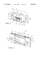
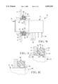
- FIG. 1 is an isometric view of an electrical connector which can be used with a capacitive coupling
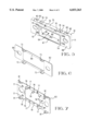
- FIG. 2 is an exploded isometric view of the connector
- FIG. 3 is an exploded isometric view of the connector from a different angle
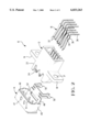
- FIG. 4 is an isometric view of a capacitive coupling for use with the connector of FIG. 1;
- FIG. 5 is an isometric view of a dielectric member used in the capacitive coupling
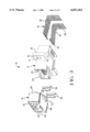
- FIGS. 6 and 7 are isometric views of the front and rear conductive sheets of the capacitive coupling
- FIG. 8 is a side view of the connector and a cross-sectional view through a portion of the capacitive coupling
- FIG. 9 is an enlarged portion of FIG. 8 showing a dielectric spacer between a shell of the connector and a conductive sheet of the capacitive coupling.
- FIG. 10 is an alternate embodiment of a connector with capacitive coupling assembly.
- the connector 10 for use with electronic equipment such as a computer and peripheral devices.
- the connector 10 comprises a dielectric housing 12, a conductive shell 14 and a plurality of contacts 16.
- the housing 12 has a forward end 22 with a cavity 24 which defines a receptacle for a mating electrical connector such as a connector on the end of an interconnect cable.
- Each of the contacts 16 has a mating end 32 which is exposed in the cavity 24 for mating engagement with a contact of the mating connector, a retention section 34 with barbed edges 36 to secure the contact in the housing, and a lead 38 which is insertable in a plated through-hole in a circuit board in the electronic equipment.
- the housing 12 has a pair of mounting pads 18 each with a front face 19 which defines a mounting surface of the connector 10.
- Each of the mounting pads 18 has a hole 21 for receiving a fastener to connect the housing 12 to a panel of the equipment.
- the shell 14 is mounted on the forward end 22 of the housing 12 and has a front face 42 with an opening 44 which is aligned with the entrance to the cavity 24.
- the shell has resilient arms 46 which extend from the front face 42 into the cavity 24 for engagement with a shell on the mating connector.
- the shell 14 is stamped and formed from electrically conductive sheet material and includes a top wall 47, a bottom wall 48, and side walls 49 which closely surround the forward end 22 of the housing. Extending from the bottom wall 48 of the shell are two pairs of resilient legs 50 which are engageable in respective holes in the circuit board to secure and support the I/O connector on the circuit board.
- the shell 14 has an upper flange 51 and a lower flange 52 each with a forward surface which is substantially coplanar with the mounting surfaces defined by the front faces 19 of the mounting pads.
- a capacitive coupling assembly 60 in the form of a gasket is disposed between the I/O connector 10 and the panel of the electronic equipment.
- capacitive coupling 60 comprises a dielectric member 61 which is sandwiched between sheets of conductive material 62, 63.
- the capacitive coupling has a central aperture 64 which is dimensioned so that the capacitive coupling can be installed on the connector 10 (FIGS. 1-3) with the forward end 22 of the connector including the shell 14 extending through the aperture.
- the capacitive coupling assembly 60 has through-holes 65 which are alignable with the holes 21 in the mounting pads of the connector to receive the same fasteners which secure the connector to the equipment panel.
- each hole 66 has a diameter passing through the conductive sheet 62 which is larger than the diameter of the hole 65 passing through the dielectric member 61, in order to avoid contact of the conductive sheet 62 with the fastener received in the hole, for a reason which will become fully apparent hereinafter.
- the dielectric member 61 is preferably made from a rigid plastic material, although an elastomeric material could also be used.
- Dielectric member 61 is shown to include a flange 67 extending forwardly from front face 68 at the periphery of aperture 64 through a slightly larger cutout 69 of front conductive sheet 62, to extend into the panel cutout (FIGS. 8 and 9).
- the dielectic member has a number of passageways 70, eight passageways in the present example, which extend between front and back faces 68, 71 of the member 61.
- a mini-capacitor 72 Disposed loosely within each of the passageways 70 will be a mini-capacitor 72 of a type which is commercially available in various sizes and capacitances from a number of sources such as from Novacap in Valencia, Calif. (see FIGS. 8 and 9).
- the capacitors 72 will be oriented so that opposite first and second ends of each capacitor are exposed near the front and back faces of the dielectric member 61, thereby effecting a capacitance between the electrodes defined on the exposed ends of the capacitors.
- FIG. 6 illustrates front conductive sheet 62, that is shown to include latch arms 73 extending rearwardly from the outer peripheral edge of the sheet, to be received into recesses 74 along the outer peripheral side surface 75 of dielectric member 61 to latch onto latch projections 76 thereof, thereby selfsecuring to the dielectric member.
- the conductive sheet 63 is stamped and formed to have resilient spring fingers 77 and spring arms 78.
- Spring fingers 77 are arranged to be in registration with the capacitors 72 in the passageways 70 when the conductive sheet 63 is attached to the dielectric member 61.
- Conductive sheet 63 is adapted to become groundingly engaged to the connector shell 14 by means of spring arms 78 that extend into aperture 64 and are angled forwardly to free ends 79 that will become spring biased against the outer surface of the connector shell 14 when the capacitive coupling assembly is assembled to the connector. Upon such assembly, free ends 79 will be deflected into relief openings 80 in the dielectric member 61 adjacent rear face 71, along aperture 64 (see FIGS. 8 and 9).
- Rear conductive sheet 63 also includes latch arms 81 extending forwardly from outer peripheral sheet edge to be received into recesses 82 (FIGS. 4 and 5) along the outer peripheral side surface 75 of dielectric member 61 staggered laterally from recesses 74, to become latched to latch projections 83 thereof and thereby selfsecure to the dielectric member.
- FIG. 8 is a cross-sectional view showing the connector 10 and the capacitive coupling assembly 60 mounted to an equipment panel 4, with FIG. 9 being an enlarged view of a portion thereof.
- the forward end of the connector extends through a hole 5 in the panel 4.
- the conductive sheet 62 of the capacitive coupling is engaged with the panel 4, and the conductive sheet 63 is engaged with the upper flange 51 and the lower flange 52 of the shell 14.
- a key or other polarizing feature is provided to ensure that the capacitive coupling is correctly oriented with the conductive sheet 62 abutting the panel 4.
- the resilient fingers 77 of the conductive sheet 63 are engaged with the top surface 47 and the bottom surface 48 of the shell. Each spring finger 77 urges the capacitor 72 against the conductive sheet 62, thereby forming an electrical path through the capacitor.
- a dielectric spacer be provided to electrically insulate the conductive sheet 62 from the shell 14.
- the hole 5 in the panel is dimensioned such that there is a gap between the panel 4 and the shell 14 around the entire periphery of the shell, into which is received flange 67 of dielectric member 61 of the capacitive coupling assembly 60.
- FIG. 10 shows an alternative embodiment of a capacitive coupling assembly 90 and associated connector 91.
- An insulative gap is assured between the panel and the connector shell 92 by a rib 93 of the connector housing 94 which extends through a slot in the shell 92.
- the capacitive coupling of the present invention is useful with a conventional shielded connector without requiring any modification to the connector.
- a capacitive coupling has been described in conjunction with a receptacle connector having a receptacle portion which receives a mating portion of a plug connector, it should be apparent that the capacitive coupling could be readily adapted to various other connector types, and all such adaptations are considered to be within the scope of the invention.
Abstract
Description
Claims (5)
Priority Applications (2)
| Application Number | Priority Date | Filing Date | Title |
|---|---|---|---|
| US08/949,668 US6033263A (en) | 1996-10-15 | 1997-10-14 | Electrically connector with capacitive coupling |
| US09/047,748 US5975958A (en) | 1997-10-14 | 1998-03-24 | Capactive coupling adapter for an electrical connector |
Applications Claiming Priority (2)
| Application Number | Priority Date | Filing Date | Title |
|---|---|---|---|
| US2754596P | 1996-10-15 | 1996-10-15 | |
| US08/949,668 US6033263A (en) | 1996-10-15 | 1997-10-14 | Electrically connector with capacitive coupling |
Related Child Applications (1)
| Application Number | Title | Priority Date | Filing Date |
|---|---|---|---|
| US09/047,748 Continuation-In-Part US5975958A (en) | 1997-10-14 | 1998-03-24 | Capactive coupling adapter for an electrical connector |
Publications (1)
| Publication Number | Publication Date |
|---|---|
| US6033263A true US6033263A (en) | 2000-03-07 |
Family
ID=26702596
Family Applications (1)
| Application Number | Title | Priority Date | Filing Date |
|---|---|---|---|
| US08/949,668 Expired - Lifetime US6033263A (en) | 1996-10-15 | 1997-10-14 | Electrically connector with capacitive coupling |
Country Status (1)
| Country | Link |
|---|---|
| US (1) | US6033263A (en) |
Cited By (20)
| Publication number | Priority date | Publication date | Assignee | Title |
|---|---|---|---|---|
| US6203371B1 (en) * | 1998-03-05 | 2001-03-20 | Universal Avionics Systems Corporation-Instrument Division | Method and apparatus for capping and grounding an electrical connector to prevent leakage of electromagnetic interference |
| US6231384B1 (en) * | 1999-12-29 | 2001-05-15 | Hon Hai Precision Ind. Co., Ltd. | Panel mounted cable end connector |
| US6398588B1 (en) * | 1999-12-30 | 2002-06-04 | Intel Corporation | Method and apparatus to reduce EMI leakage through an isolated connector housing using capacitive coupling |
| US6402532B1 (en) * | 2001-06-22 | 2002-06-11 | Jess -Link Products Co., Ltd. | Pressing bar for connecting legs of connectors |
| WO2003019733A1 (en) * | 2001-08-23 | 2003-03-06 | Intel Corporation | Electromagnetic emission reduction technique for shielded connectors |
| US6709286B1 (en) * | 2002-10-03 | 2004-03-23 | Hon Hai Precision Ind. Co., Ltd. | Electrical connector |
| US20040066249A1 (en) * | 2002-10-03 | 2004-04-08 | Garner Robert Barton | Scalable computer system having surface-mounted capacitive couplers for intercommunication |
| US6733339B2 (en) * | 1997-03-07 | 2004-05-11 | Berg Technology, Inc. | Shielded connector with integral latching and ground structure |
| US20040095201A1 (en) * | 2002-07-12 | 2004-05-20 | Massachusetts Institute Of Technology | Electromagnetic coupling connector for three-dimensional electronic circuits |
| US6858793B1 (en) * | 1999-09-09 | 2005-02-22 | Koninklijke Philips Electronics N.V. | EMI-suppression plate for use in IEEE-1394 applications |
| US20050221656A1 (en) * | 2004-03-30 | 2005-10-06 | Japan Aviation Electronics Industry, Limited | Connector which can easily be mounted to an object and provided with EMI protection |
| US6971915B1 (en) * | 2004-07-22 | 2005-12-06 | Hon Hai Precision Ind. Co., Ltd. | Electrical connector with steady mating frame |
| US20060046563A1 (en) * | 2004-08-31 | 2006-03-02 | Hirose Electric Co., Ltd. | Electrical connector |
| US20060079112A1 (en) * | 2004-10-08 | 2006-04-13 | Shuey Scott A | Shielded blind-mate connector |
| US20070178762A1 (en) * | 2006-02-02 | 2007-08-02 | Tyco Electronics Corporation | Connector with compliant EMI gasket |
| US20080032554A1 (en) * | 2006-08-02 | 2008-02-07 | Hon Hai Precision Ind. Co., Ltd. | Electrical connector assembly with improved covers |
| US20080038959A1 (en) * | 2006-08-08 | 2008-02-14 | International Business Machines Corporation | Universal emc gasket |
| US20110177715A1 (en) * | 2007-11-05 | 2011-07-21 | Tyco Electronics Amp Gmbh | Electrical plug connector |
| US20130005185A1 (en) * | 2011-06-30 | 2013-01-03 | Hon Hai Precision Industry Co., Ltd. | Input/output connector assembly |
| US10312646B2 (en) * | 2013-07-19 | 2019-06-04 | Foxconn Interconnect Technology Limited | Flippable electrical connector |
Citations (25)
| Publication number | Priority date | Publication date | Assignee | Title |
|---|---|---|---|---|
| US4386814A (en) * | 1981-08-17 | 1983-06-07 | Amp Incorporated | Kit for converting a panel opening to a shielded pin receptacle |
| EP0123457A1 (en) * | 1983-03-30 | 1984-10-31 | E.I. Du Pont De Nemours And Company | Filter connector |
| US4500159A (en) * | 1983-08-31 | 1985-02-19 | Allied Corporation | Filter electrical connector |
| US4643509A (en) * | 1984-06-15 | 1987-02-17 | Amp Incorporated | Grounding clip for filtered electrical connector |
| US4772221A (en) * | 1986-11-25 | 1988-09-20 | Amphenol Corporation | Panel mount connector filter assembly |
| US4797120A (en) * | 1987-12-15 | 1989-01-10 | Amp Incorporated | Coaxial connector having filtered ground isolation means |
| US4853659A (en) * | 1988-03-17 | 1989-08-01 | Amp Incorporated | Planar pi-network filter assembly having capacitors formed on opposing surfaces of an inductive member |
| US4884982A (en) * | 1989-04-03 | 1989-12-05 | Amp Incorporated | Capacitive coupled connector |
| US4931754A (en) * | 1987-07-14 | 1990-06-05 | E. I. Du Pont De Nemours And Company | Filter unit for connectors having filter capacitors formed on opposing surfaces of a substrate |
| US4934960A (en) * | 1990-01-04 | 1990-06-19 | Amp Incorporated | Capacitive coupled connector with complex insulative body |
| US5018989A (en) * | 1990-09-21 | 1991-05-28 | Amp Incorporated | Electrical connector containing components and method of making same |
| US5062811A (en) * | 1990-10-30 | 1991-11-05 | Amp Incorporated | Capacitive coupled connector for PCB grounding |
| US5147224A (en) * | 1991-05-29 | 1992-09-15 | Foxconn International, Inc. | Electrical connector with conductive member electrically coupling contacts and filter components |
| US5151054A (en) * | 1991-05-22 | 1992-09-29 | Amphenol Corporation | Electrical connector shell and grounding spring therefor |
| US5152699A (en) * | 1990-11-27 | 1992-10-06 | Thomas & Betts Corporation | Filtered plug connector |
| US5246389A (en) * | 1993-02-23 | 1993-09-21 | Amphenol Corporation | High density, filtered electrical connector |
| US5326280A (en) * | 1993-06-14 | 1994-07-05 | Amphenol Corporation | Coaxial connector with integral decoupling unit |
| US5331505A (en) * | 1993-01-08 | 1994-07-19 | Honeywell Inc. | Multi-coplanar capacitor for electrical connector |
| US5401192A (en) * | 1994-03-28 | 1995-03-28 | Amphenol Corporation | Combination connector |
| US5513065A (en) * | 1992-12-23 | 1996-04-30 | Panduit Corp. | Communication connector with capacitor label |
| US5554050A (en) * | 1995-03-09 | 1996-09-10 | The Whitaker Corporation | Filtering insert for electrical connectors |
| US5738541A (en) * | 1996-04-09 | 1998-04-14 | Hon Hai Precision Ind. Co., Ltd. | Assembling mechanism of connector having boardlock and spacer |
| US5752854A (en) * | 1997-02-18 | 1998-05-19 | The Whitaker Corporation | Panel mount structure |
| US5769666A (en) * | 1996-12-27 | 1998-06-23 | Hon Hai Precision Ind. Co., Ltd. | Filtered connector |
| US5865646A (en) * | 1997-03-07 | 1999-02-02 | Berg Technology, Inc. | Connector shield with integral latching and ground structure |
-
1997
- 1997-10-14 US US08/949,668 patent/US6033263A/en not_active Expired - Lifetime
Patent Citations (25)
| Publication number | Priority date | Publication date | Assignee | Title |
|---|---|---|---|---|
| US4386814A (en) * | 1981-08-17 | 1983-06-07 | Amp Incorporated | Kit for converting a panel opening to a shielded pin receptacle |
| EP0123457A1 (en) * | 1983-03-30 | 1984-10-31 | E.I. Du Pont De Nemours And Company | Filter connector |
| US4500159A (en) * | 1983-08-31 | 1985-02-19 | Allied Corporation | Filter electrical connector |
| US4643509A (en) * | 1984-06-15 | 1987-02-17 | Amp Incorporated | Grounding clip for filtered electrical connector |
| US4772221A (en) * | 1986-11-25 | 1988-09-20 | Amphenol Corporation | Panel mount connector filter assembly |
| US4931754A (en) * | 1987-07-14 | 1990-06-05 | E. I. Du Pont De Nemours And Company | Filter unit for connectors having filter capacitors formed on opposing surfaces of a substrate |
| US4797120A (en) * | 1987-12-15 | 1989-01-10 | Amp Incorporated | Coaxial connector having filtered ground isolation means |
| US4853659A (en) * | 1988-03-17 | 1989-08-01 | Amp Incorporated | Planar pi-network filter assembly having capacitors formed on opposing surfaces of an inductive member |
| US4884982A (en) * | 1989-04-03 | 1989-12-05 | Amp Incorporated | Capacitive coupled connector |
| US4934960A (en) * | 1990-01-04 | 1990-06-19 | Amp Incorporated | Capacitive coupled connector with complex insulative body |
| US5018989A (en) * | 1990-09-21 | 1991-05-28 | Amp Incorporated | Electrical connector containing components and method of making same |
| US5062811A (en) * | 1990-10-30 | 1991-11-05 | Amp Incorporated | Capacitive coupled connector for PCB grounding |
| US5152699A (en) * | 1990-11-27 | 1992-10-06 | Thomas & Betts Corporation | Filtered plug connector |
| US5151054A (en) * | 1991-05-22 | 1992-09-29 | Amphenol Corporation | Electrical connector shell and grounding spring therefor |
| US5147224A (en) * | 1991-05-29 | 1992-09-15 | Foxconn International, Inc. | Electrical connector with conductive member electrically coupling contacts and filter components |
| US5513065A (en) * | 1992-12-23 | 1996-04-30 | Panduit Corp. | Communication connector with capacitor label |
| US5331505A (en) * | 1993-01-08 | 1994-07-19 | Honeywell Inc. | Multi-coplanar capacitor for electrical connector |
| US5246389A (en) * | 1993-02-23 | 1993-09-21 | Amphenol Corporation | High density, filtered electrical connector |
| US5326280A (en) * | 1993-06-14 | 1994-07-05 | Amphenol Corporation | Coaxial connector with integral decoupling unit |
| US5401192A (en) * | 1994-03-28 | 1995-03-28 | Amphenol Corporation | Combination connector |
| US5554050A (en) * | 1995-03-09 | 1996-09-10 | The Whitaker Corporation | Filtering insert for electrical connectors |
| US5738541A (en) * | 1996-04-09 | 1998-04-14 | Hon Hai Precision Ind. Co., Ltd. | Assembling mechanism of connector having boardlock and spacer |
| US5769666A (en) * | 1996-12-27 | 1998-06-23 | Hon Hai Precision Ind. Co., Ltd. | Filtered connector |
| US5752854A (en) * | 1997-02-18 | 1998-05-19 | The Whitaker Corporation | Panel mount structure |
| US5865646A (en) * | 1997-03-07 | 1999-02-02 | Berg Technology, Inc. | Connector shield with integral latching and ground structure |
Cited By (36)
| Publication number | Priority date | Publication date | Assignee | Title |
|---|---|---|---|---|
| US6733339B2 (en) * | 1997-03-07 | 2004-05-11 | Berg Technology, Inc. | Shielded connector with integral latching and ground structure |
| US6203371B1 (en) * | 1998-03-05 | 2001-03-20 | Universal Avionics Systems Corporation-Instrument Division | Method and apparatus for capping and grounding an electrical connector to prevent leakage of electromagnetic interference |
| US6858793B1 (en) * | 1999-09-09 | 2005-02-22 | Koninklijke Philips Electronics N.V. | EMI-suppression plate for use in IEEE-1394 applications |
| US6231384B1 (en) * | 1999-12-29 | 2001-05-15 | Hon Hai Precision Ind. Co., Ltd. | Panel mounted cable end connector |
| US6398588B1 (en) * | 1999-12-30 | 2002-06-04 | Intel Corporation | Method and apparatus to reduce EMI leakage through an isolated connector housing using capacitive coupling |
| US6402532B1 (en) * | 2001-06-22 | 2002-06-11 | Jess -Link Products Co., Ltd. | Pressing bar for connecting legs of connectors |
| WO2003019733A1 (en) * | 2001-08-23 | 2003-03-06 | Intel Corporation | Electromagnetic emission reduction technique for shielded connectors |
| US6700455B2 (en) | 2001-08-23 | 2004-03-02 | Intel Corporation | Electromagnetic emission reduction technique for shielded connectors |
| CN1324769C (en) * | 2001-08-23 | 2007-07-04 | 英特尔公司 | Electromagnetic emission reduction technique for shielded connectors |
| US6891447B2 (en) | 2002-07-12 | 2005-05-10 | Massachusetts Institute Of Technology | Electromagnetic coupling connector for three-dimensional electronic circuits |
| US20040095201A1 (en) * | 2002-07-12 | 2004-05-20 | Massachusetts Institute Of Technology | Electromagnetic coupling connector for three-dimensional electronic circuits |
| US7385457B2 (en) | 2002-10-03 | 2008-06-10 | International Business Machines Corporation | Flexible capacitive coupler assembly and method of manufacture |
| US20040067682A1 (en) * | 2002-10-03 | 2004-04-08 | Korsunsky Iosif R. | Electrical connector |
| US6709286B1 (en) * | 2002-10-03 | 2004-03-23 | Hon Hai Precision Ind. Co., Ltd. | Electrical connector |
| US7038553B2 (en) | 2002-10-03 | 2006-05-02 | International Business Machines Corporation | Scalable computer system having surface-mounted capacitive couplers for intercommunication |
| US20080238582A1 (en) * | 2002-10-03 | 2008-10-02 | International Business Machines Corporation | Flexible Capacitive Coupler Assembly And Method Of Manufacture |
| US20040066249A1 (en) * | 2002-10-03 | 2004-04-08 | Garner Robert Barton | Scalable computer system having surface-mounted capacitive couplers for intercommunication |
| US20050221656A1 (en) * | 2004-03-30 | 2005-10-06 | Japan Aviation Electronics Industry, Limited | Connector which can easily be mounted to an object and provided with EMI protection |
| CN100379094C (en) * | 2004-03-30 | 2008-04-02 | 日本航空电子工业株式会社 | Connector which can easily be mounted to an object and provided with EMI protection |
| US7077696B2 (en) * | 2004-03-30 | 2006-07-18 | Japan Aviation Electronics Industry, Ltd. | Connector which can easily be mounted to an object and provided with EMI protection |
| US6971915B1 (en) * | 2004-07-22 | 2005-12-06 | Hon Hai Precision Ind. Co., Ltd. | Electrical connector with steady mating frame |
| US20060046563A1 (en) * | 2004-08-31 | 2006-03-02 | Hirose Electric Co., Ltd. | Electrical connector |
| US7044782B2 (en) * | 2004-08-31 | 2006-05-16 | Hirose Electric Co., Ltd. | Electrical connector |
| US7074084B2 (en) * | 2004-10-08 | 2006-07-11 | Tyco Electronics Corporation | Shielded blind-mate connector |
| US20060079112A1 (en) * | 2004-10-08 | 2006-04-13 | Shuey Scott A | Shielded blind-mate connector |
| US7473131B2 (en) * | 2006-02-02 | 2009-01-06 | Tyco Electronics Corporation | Connector with compliant EMI gasket |
| US20070178762A1 (en) * | 2006-02-02 | 2007-08-02 | Tyco Electronics Corporation | Connector with compliant EMI gasket |
| US7416449B2 (en) * | 2006-08-02 | 2008-08-26 | Hon Hai Precision Ind. Co., Ltd. | Electrical connector assembly with improved covers |
| US20080032554A1 (en) * | 2006-08-02 | 2008-02-07 | Hon Hai Precision Ind. Co., Ltd. | Electrical connector assembly with improved covers |
| US7357675B2 (en) * | 2006-08-08 | 2008-04-15 | International Business Machines Corporation | Universal EMC gasket |
| US20080038959A1 (en) * | 2006-08-08 | 2008-02-14 | International Business Machines Corporation | Universal emc gasket |
| US20110177715A1 (en) * | 2007-11-05 | 2011-07-21 | Tyco Electronics Amp Gmbh | Electrical plug connector |
| US8500486B2 (en) * | 2007-11-05 | 2013-08-06 | Tyco Electronics Amp Gmbh | Electrical plug connector |
| US20130005185A1 (en) * | 2011-06-30 | 2013-01-03 | Hon Hai Precision Industry Co., Ltd. | Input/output connector assembly |
| US8512076B2 (en) * | 2011-06-30 | 2013-08-20 | Hong Fu Jin Precision Industry (Wuhan) Co., Ltd. | Input/output connector assembly |
| US10312646B2 (en) * | 2013-07-19 | 2019-06-04 | Foxconn Interconnect Technology Limited | Flippable electrical connector |
Similar Documents
| Publication | Publication Date | Title |
|---|---|---|
| US6033263A (en) | Electrically connector with capacitive coupling | |
| US5975958A (en) | Capactive coupling adapter for an electrical connector | |
| US5256074A (en) | Connector having improved electrostatic discharge protection | |
| US6206728B1 (en) | Shielded electrical connector system | |
| US6354875B1 (en) | Electrical connector with a rear shield | |
| EP0653816B1 (en) | Filtered electrical connector assembly | |
| EP0521648B1 (en) | Electrical connector with electrostatic discharge protection | |
| US5772466A (en) | Receptacle connector detecting mating with different plugs | |
| US7108554B2 (en) | Electrical connector with shielding member | |
| US5281169A (en) | Shielded electrical connector assemblies | |
| US5695362A (en) | Hybrid grounded and stacked connector assembly with audio jacks | |
| US5913690A (en) | Electrical grounding shroud | |
| US5674083A (en) | ESD protected electrical connector | |
| US20080038963A1 (en) | Receptacle connector and apparatus having the same | |
| US6036545A (en) | Decoupled BNC connector | |
| KR950021892A (en) | Electrical connector assembly | |
| JP2010503154A (en) | Electrical connector with electrostatic discharge protection | |
| US5755592A (en) | Combined ground strap and board lock for electrical connector assembly | |
| US6948980B2 (en) | Shielded electrical connector | |
| US6786770B1 (en) | Shielded electrical connector | |
| US5281155A (en) | Electrical connector with electrostatic discharge protection | |
| US7976321B2 (en) | Electrical connector with a ground terminal | |
| EP0835536B1 (en) | Filtered electrical connector | |
| US6042398A (en) | Electrical connector having improved grounding arrangement | |
| US6786775B1 (en) | Modular jack assembly |
Legal Events
| Date | Code | Title | Description |
|---|---|---|---|
| AS | Assignment |
Owner name: WHITAKER CORPORATION, THE, DELAWARE Free format text: ASSIGNMENT OF ASSIGNORS INTEREST;ASSIGNORS:WEIDLER, CHARLES HARRY;WHITEMAN, ROBERT NEIL, JR.;REEL/FRAME:008859/0815;SIGNING DATES FROM 19971212 TO 19971215 |
|
| STCF | Information on status: patent grant |
Free format text: PATENTED CASE |
|
| FPAY | Fee payment |
Year of fee payment: 4 |
|
| FPAY | Fee payment |
Year of fee payment: 8 |
|
| REMI | Maintenance fee reminder mailed | ||
| FPAY | Fee payment |
Year of fee payment: 12 |
|
| AS | Assignment |
Owner name: TYCO ELECTRONICS SERVICES GMBH, SWITZERLAND Free format text: ASSIGNMENT OF ASSIGNORS INTEREST;ASSIGNOR:THE WHITAKER LLC;REEL/FRAME:040283/0940 Effective date: 20161001 |