US6033724A - Golf ball mold preparation technique and coating system - Google Patents
Golf ball mold preparation technique and coating system Download PDFInfo
- Publication number
- US6033724A US6033724A US09/178,633 US17863398A US6033724A US 6033724 A US6033724 A US 6033724A US 17863398 A US17863398 A US 17863398A US 6033724 A US6033724 A US 6033724A
- Authority
- US
- United States
- Prior art keywords
- mold
- top coat
- golf ball
- coating
- primer
- Prior art date
- Legal status (The legal status is an assumption and is not a legal conclusion. Google has not performed a legal analysis and makes no representation as to the accuracy of the status listed.)
- Expired - Lifetime
Links
Images

Classifications
-
- B—PERFORMING OPERATIONS; TRANSPORTING
- B05—SPRAYING OR ATOMISING IN GENERAL; APPLYING FLUENT MATERIALS TO SURFACES, IN GENERAL
- B05D—PROCESSES FOR APPLYING FLUENT MATERIALS TO SURFACES, IN GENERAL
- B05D5/00—Processes for applying liquids or other fluent materials to surfaces to obtain special surface effects, finishes or structures
- B05D5/08—Processes for applying liquids or other fluent materials to surfaces to obtain special surface effects, finishes or structures to obtain an anti-friction or anti-adhesive surface
- B05D5/083—Processes for applying liquids or other fluent materials to surfaces to obtain special surface effects, finishes or structures to obtain an anti-friction or anti-adhesive surface involving the use of fluoropolymers
-
- A—HUMAN NECESSITIES
- A63—SPORTS; GAMES; AMUSEMENTS
- A63B—APPARATUS FOR PHYSICAL TRAINING, GYMNASTICS, SWIMMING, CLIMBING, OR FENCING; BALL GAMES; TRAINING EQUIPMENT
- A63B37/00—Solid balls; Rigid hollow balls; Marbles
- A63B37/0003—Golf balls
- A63B37/0022—Coatings, e.g. paint films; Markings
- A63B37/00221—Coatings, e.g. paint films; Markings characterised by the material
-
- A—HUMAN NECESSITIES
- A63—SPORTS; GAMES; AMUSEMENTS
- A63B—APPARATUS FOR PHYSICAL TRAINING, GYMNASTICS, SWIMMING, CLIMBING, OR FENCING; BALL GAMES; TRAINING EQUIPMENT
- A63B45/00—Apparatus or methods for manufacturing balls
-
- B—PERFORMING OPERATIONS; TRANSPORTING
- B29—WORKING OF PLASTICS; WORKING OF SUBSTANCES IN A PLASTIC STATE IN GENERAL
- B29C—SHAPING OR JOINING OF PLASTICS; SHAPING OF MATERIAL IN A PLASTIC STATE, NOT OTHERWISE PROVIDED FOR; AFTER-TREATMENT OF THE SHAPED PRODUCTS, e.g. REPAIRING
- B29C33/00—Moulds or cores; Details thereof or accessories therefor
- B29C33/56—Coatings, e.g. enameled or galvanised; Releasing, lubricating or separating agents
- B29C33/60—Releasing, lubricating or separating agents
- B29C33/62—Releasing, lubricating or separating agents based on polymers or oligomers
-
- B—PERFORMING OPERATIONS; TRANSPORTING
- B29—WORKING OF PLASTICS; WORKING OF SUBSTANCES IN A PLASTIC STATE IN GENERAL
- B29C—SHAPING OR JOINING OF PLASTICS; SHAPING OF MATERIAL IN A PLASTIC STATE, NOT OTHERWISE PROVIDED FOR; AFTER-TREATMENT OF THE SHAPED PRODUCTS, e.g. REPAIRING
- B29C37/00—Component parts, details, accessories or auxiliary operations, not covered by group B29C33/00 or B29C35/00
- B29C37/0025—Applying surface layers, e.g. coatings, decorative layers, printed layers, to articles during shaping, e.g. in-mould printing
- B29C37/0028—In-mould coating, e.g. by introducing the coating material into the mould after forming the article
- B29C37/0032—In-mould coating, e.g. by introducing the coating material into the mould after forming the article the coating being applied upon the mould surface before introducing the moulding compound, e.g. applying a gelcoat
-
- B—PERFORMING OPERATIONS; TRANSPORTING
- B29—WORKING OF PLASTICS; WORKING OF SUBSTANCES IN A PLASTIC STATE IN GENERAL
- B29C—SHAPING OR JOINING OF PLASTICS; SHAPING OF MATERIAL IN A PLASTIC STATE, NOT OTHERWISE PROVIDED FOR; AFTER-TREATMENT OF THE SHAPED PRODUCTS, e.g. REPAIRING
- B29C37/00—Component parts, details, accessories or auxiliary operations, not covered by group B29C33/00 or B29C35/00
- B29C37/0067—Using separating agents during or after moulding; Applying separating agents on preforms or articles, e.g. to prevent sticking to each other
-
- B—PERFORMING OPERATIONS; TRANSPORTING
- B29—WORKING OF PLASTICS; WORKING OF SUBSTANCES IN A PLASTIC STATE IN GENERAL
- B29C—SHAPING OR JOINING OF PLASTICS; SHAPING OF MATERIAL IN A PLASTIC STATE, NOT OTHERWISE PROVIDED FOR; AFTER-TREATMENT OF THE SHAPED PRODUCTS, e.g. REPAIRING
- B29C45/00—Injection moulding, i.e. forcing the required volume of moulding material through a nozzle into a closed mould; Apparatus therefor
- B29C45/17—Component parts, details or accessories; Auxiliary operations
- B29C45/26—Moulds
- B29C45/37—Mould cavity walls, i.e. the inner surface forming the mould cavity, e.g. linings
-
- B—PERFORMING OPERATIONS; TRANSPORTING
- B32—LAYERED PRODUCTS
- B32B—LAYERED PRODUCTS, i.e. PRODUCTS BUILT-UP OF STRATA OF FLAT OR NON-FLAT, e.g. CELLULAR OR HONEYCOMB, FORM
- B32B27/00—Layered products comprising a layer of synthetic resin
- B32B27/32—Layered products comprising a layer of synthetic resin comprising polyolefins
- B32B27/322—Layered products comprising a layer of synthetic resin comprising polyolefins comprising halogenated polyolefins, e.g. PTFE
-
- A—HUMAN NECESSITIES
- A63—SPORTS; GAMES; AMUSEMENTS
- A63B—APPARATUS FOR PHYSICAL TRAINING, GYMNASTICS, SWIMMING, CLIMBING, OR FENCING; BALL GAMES; TRAINING EQUIPMENT
- A63B45/00—Apparatus or methods for manufacturing balls
- A63B45/02—Marking of balls
-
- Y—GENERAL TAGGING OF NEW TECHNOLOGICAL DEVELOPMENTS; GENERAL TAGGING OF CROSS-SECTIONAL TECHNOLOGIES SPANNING OVER SEVERAL SECTIONS OF THE IPC; TECHNICAL SUBJECTS COVERED BY FORMER USPC CROSS-REFERENCE ART COLLECTIONS [XRACs] AND DIGESTS
- Y10—TECHNICAL SUBJECTS COVERED BY FORMER USPC
- Y10T—TECHNICAL SUBJECTS COVERED BY FORMER US CLASSIFICATION
- Y10T428/00—Stock material or miscellaneous articles
- Y10T428/31504—Composite [nonstructural laminate]
- Y10T428/3154—Of fluorinated addition polymer from unsaturated monomers
- Y10T428/31544—Addition polymer is perhalogenated
-
- Y—GENERAL TAGGING OF NEW TECHNOLOGICAL DEVELOPMENTS; GENERAL TAGGING OF CROSS-SECTIONAL TECHNOLOGIES SPANNING OVER SEVERAL SECTIONS OF THE IPC; TECHNICAL SUBJECTS COVERED BY FORMER USPC CROSS-REFERENCE ART COLLECTIONS [XRACs] AND DIGESTS
- Y10—TECHNICAL SUBJECTS COVERED BY FORMER USPC
- Y10T—TECHNICAL SUBJECTS COVERED BY FORMER US CLASSIFICATION
- Y10T428/00—Stock material or miscellaneous articles
- Y10T428/31504—Composite [nonstructural laminate]
- Y10T428/31678—Of metal
- Y10T428/31692—Next to addition polymer from unsaturated monomers
- Y10T428/31699—Ester, halide or nitrile of addition polymer
Definitions
- the present invention relates generally to game ball molds, and more particularly, to a method of preparing a game ball mold cavity for application of a coating system.
- the invention also relates to a dual region coating system which provides for good release of game ball products while providing a relatively long useful life for a single application of the system.
- Solid multi-piece (two or more piece) golf balls typically have a spherical core formed from polybutadiene, zinc diacrylate and/or zinc dimethacrylate, and a peroxide initiator.
- One-piece golf balls generally have a similar composition.
- the cores and one-piece balls conveniently can be compression molded at an elevated temperature in a metallic mold having a surface coating of, e.g., polytetrafluoroethylene (PTFE).
- PTFE polytetrafluoroethylene
- Such mold coatings provide for good release of golf ball cores from the molds.
- a non-stick coating material such as PTFE is required due to the presence of zinc diacrylate and/or zinc dimethacrylate, which have adhesive qualities.
- An object of the invention is to provide a method of preparing a game ball mold cavity for application of a non-stick coating.
- Another object of the invention is to provide a mold coating technique which does not result in excessive wear to the mold cavity itself.
- Another object of the invention is to provide a dual region coating system for game ball molds, such as golf ball mold cavities, the coating system having a prolonged useful life.
- Another object of the invention is to provide a game ball mold for zinc diacrylate--and/or zinc dimethacrylate--containing game ball products with good release.
- a further object of the invention is to provide a method of coating a game ball mold cavity with a long lasting coating.
- Yet another object of the invention is to provide a golf ball mold which is particularly well suited for making golf ball cores and one-piece golf balls.
- a further object of the invention is to provide a convenient and economical method for coating golf ball mold cavities.
- the invention in a preferred form is a method of preparing a used game ball mold cavity for application of a coating.
- the method comprises the steps of obtaining a metallic game ball mold cavity having a land area and a wall defining a hemispherical opening, pretreating the land area and wall by contacting the mold cavity with an abrasive media until substantially all of any previous coating has been removed, and blasting the land area and wall with aluminum oxide media having a grit of about 180-400 under conditions sufficient to obtain a surface penetration of less than 0.2 mils.
- the abrasive media used in the pretreating step preferably is steel shop.
- the abrasive media preferably is applied by shot peening.
- the game ball mold preferably comprises stainless steel.
- Another preferred form of the invention is a method of coating a game ball mold cavity comprising the steps of obtaining a metallic game ball mold cavity having a land area and a wall defining a hemispherical opening, pretreating the land area and wall by contacting the mold cavity with an abrasive media until substantially all of the prior coating has been removed blasting the land area and wall with aluminum oxide media having a grit of about 180-400 under conditions sufficient to obtain a surface penetration of less than 0.2 mils, applying a primer of perfluoroalcoxy resin (PFA) to the land area and wall, and applying a top coat of perfluoroalcoxy resin (PFA) to the land area and wall.
- PFA perfluoroalcoxy resin
- the primer preferably is applied in the thickness of about 0.0003-0.0004 inches.
- the top coat preferably is applied in the thickness of about 0.0004-0.0006 inches.
- the abrasive media used in the pretreating step preferably comprises metal beads and more preferably comprises steel shot with a hardness ⁇ 45 Rockwall C.
- the invention is a coating system for a game ball mold cavity having a land area and a wall defining a hemispherical opening.
- the system comprises a first coating configured to be coated on the wall of the mold cavity and a second coating configured to be coated on the land area.
- the first coating comprises a composition which includes at least one fluorocarbon polymer selected from the group consisting of polytetrafluoroethylene (PTFE), fluorinated ethylene polymer (FEP), and polyfluoroalcoxy resin (PFA).
- the second coating comprises a composition of a metal component which is impregnated with PTFE, and which is different than the overall composition of the first coating.
- the metal component in the second coating preferably is porous, and preferably is nickel and/or chrome.
- the first coating preferably is nonmetallic, and even more preferably contains both PTFE and FEP.
- the first coating has a thickness of at least 0.0015-0.002 inches.
- the second coating preferably has a thickness of at least 0.0005-0.0010 inches.
- Yet another preferred form of the invention is a method of making a coated game ball mold cavity.
- the method comprises obtaining a game ball mold cavity having a land area and a wall defining a hemispherical opening.
- a first coating which comprises at least one fluorocarbon polymer selected from the group consisting of PTFE, FEP, and PFA, is formed on the wall of the cavity.
- a second coating which comprises a composition of metal and PTFE, and which is of a different overall composition than the first coating is formed on the land area of the mold.
- the land area is masked while the first coating is applied to the wall of the mold cavity.
- a coating is applied to the patterned cavities of an injection mold used to form the outer cover layer of a dimpled golf ball.
- the coating comprises a primer layer and a top coating having a total thickness no greater than 0.0007 inches.
- the and top coat preferably comprises a fluoropolymer material.
- the thin coating layer enables easy ejection of finished golf balls from the cavity without diminishing the aerodynamic performance of the balls.
- the land area of the injection mold can be coated with thin layers of primer and top coat materials as well.
- FIG. 1 is a flow chart showing the mold preparation technique of the invention
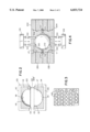
- FIG. 2 shows a side elevational view of a section of a golf ball mold which is coated in accordance with one embodiment of the dual region coating system of the present invention
- FIG. 3 is a partial top view of the lower half of a golf ball core mold.
- FIG. 4 is a sectional view of a golf ball injection mold which is coated in accordance with the invention.
- the invention relates to a mold preparation technique and to a new and useful dual region coating system.
- the mold preparation technique provides game ball mold cavities with a long useful life.
- the mold preparation technique of the invention can be used to prepare a mold cavity for application of a uniform fluorocarbon polymer coating system over both the hemispherical walls and land areas of the mold, and also can be used to prepare molds in which the hemispherical walls and land areas will be coated with different compositions.
- the dual region coating system of the present invention achieves a synergistic result because of the differences in the nature of the coatings applied in the hemispherical openings on the land areas of a mold cavity.
- the dual coating system results in a long useful life for a single coating application with good release of zinc diacrylate--and/or zinc dimethacrylate--containing game ball products such as golf ball cores and one-piece golf balls.
- FIG. 1 a flow chart of the mold preparation technique according to the invention is shown and is designated as 10.
- the hemispherical opening and the land area of the mold cavity which typically is made of stainless steel but also can be made of carbon steel or aluminum, are shot peened or air blasted with an abrasive media such as metal beads, hard plastic particles or the like in a shot peening zone 12.
- an abrasive media such as metal beads, hard plastic particles or the like in a shot peening zone 12.
- One preferred abrasive media is Guyson Metal Bead #900042.
- This step removes most of any prior coating off of the mold surfaces.
- the hemispherical opening and land area of the mold cavity are blasted with aluminum oxide powder having a grit of 180-400, more preferably 200-280, in a blasting zone 14. This grit size is substantially smaller than the 70-80 grit powder recommended by current supplies of mold preparation products. It is important to use a small grit material in order to avoid obtaining too high a penetration depth of the mold surface. A penetration depth greater than 0.01 mils but well
- the hemispherical opening and land area of the mold cavity are primed in a priming zone 16 with a PFA primer such as, e.g., Dupont 420-703 or Witford E-8878b.
- the primer has a preferred (cured) thickness of about 0.3-0.4 mils.
- the primer can be applied by spraying or another suitable technique.
- the primer is cured under appropriate conditions, such as heating in an oven at about 430° F. metal temperature for about 10-15 minutes.
- a top coating of PFA material such as Dupont 857-210 or Witford E-8878A, is applied over the primer coat in a top coating zone 18 to form a top coat layer with a (cured) thickness of about 0.4-0.6 mils.
- the top coat can be applied by spraying or another suitable technique.
- the top coat is then cured under appropriate conditions, for example at 750° F. metal temperature for 10-15 minutes.
- another aspect of the invention is a coating system for game ball mold cavities which employs different coating compositions on the hemispherical wall and on the land area of the mold cavities.
- Molds for making golf ball cores containing polybutadiene and zinc diacrylate and/or zinc dimethacrylate typically are clamshell compression molds made of stainless steel. Compression molding of golf ball cores typically takes place at 280-350° F. A cylindrical slug of golf ball core material is placed in a spherical clamshell mold cavity, which is then closed such that the spacing between the upper and lower halves of the mold is, e.g., about 0.0008 inches.
- flash a small quantity of core material referred to as "flash" extends outward from between the rims of the (nearly) mating hemispherical walls in the mold cavities onto the lands of opposite mold cavities, forming an equatorial ring around the core.
- flash typically extends outward from between the rims of the (nearly) mating hemispherical walls in the mold cavities onto the lands of opposite mold cavities, forming an equatorial ring around the core.
- the bulk of this ring of core material is separated from the cores when the cores are removed from the mold. Any remaining flash is removed by brush tumbling.
- the shear force exerted by the flash on the land areas of the mold cavity during compression molding is extremely high and tends to wear away the coating on the land area. After the coating on the land areas has begun to wear away, the flash tends to stick to the land areas when the molds are opened after compression molding.
- the metal coating impregnated with fluorocarbon polymer which is formed on the land areas of the mold cavity, provides the land areas with improved durability and abrasion resistance and thus the mold requires less frequent recoating than when conventional coating systems are used.
- a metal preferably is plated on the land area and subsequently is impregnated with a fluorocarbon polymer.
- the metal preferably is a porous metal, and more preferably is electroless nickel, chrome plate, or the like. Nickel has been formed to be particularly useful because of its porosity.
- the coating used on the second region of the mold e.g. the wall of the cavities, preferably is FEP, PTFE, PFA, or the like.
- FEP top coatings have been found particularly advantageous due to their very low surface tension.
- the coating in the cavities preferably has an overall thickness of at least 0.0015 inches, and more preferably is about 0.0018-0.002 inches thick. This provides for good release and strong adhesion of the coating to the mold upon application.
- this overall coating includes a 0.0004-0.0008 inch thick primer layer of PTFE and two top coat layers of FEP each having a thickness of about 0.0006 inches or less.
- the coating on the land areas of the mold preferably has a thickness in the range of 0.0005-0.0010 inches, and more preferably 0.0005 inches. This range of thickness provides a coating which has good adhesion and a relatively long useful life.
- FIG. 2 a section of a coated game ball mold 110 and a method of coating a game ball mold according to the invention are depicted.
- An uncoated game ball mold is obtained.
- the mold has an upper mold half 112 and a substantially identical lower mold half 114.
- Each upper mold half 112 includes a plurality of mold cavities 116, each of which includes a hemispherical inner wall 118, a circular rim 120, and a ring-shaped land area 113.
- the mold cavities 116 are mounted in a mold frame 125.
- Each lower mold half 114 includes a plurality of mold cavities 117, each of which includes a hemispherical inner wall 119, a circular rim 121, and a rim-shaped land area 115.
- the mold cavities 117 are mounted in a mold frame 126, which is shown in both FIG. 2 and FIG. 3. Adjacent upper and lower inner walls 118 and 119 form a spherical mold for a golf ball core or the like.
- the land areas of the upper and lower mold halves 112, 114 are separated by a distance of, e.g., about 0.08 inches, forming a gap 122, which is shown in exaggerated form in FIG. 2.
- the mold 110 is made of stainless steel. The upper and lower halves 112, 114 are moved together and apart by conventional means, which are not shown.
- the mold cavities 116, 117 are removed from the mold frames 125, 126. If the mold cavities have been used previously, they are cleaned in order to remove the prior coating.
- the land areas 113, 115 of the mold cavities 116, 117 are masked using any suitable means, such as metal mask or tape.
- the inner walls 118, 119 of the hemispherical mold cavities 116, 117 are lightly abraded using 180-400 grit aluminum oxide.
- a primer coating preferably comprising PTFE is applied to the inner walls 118, 119 in a thickness of 0.0005 inches, and is cured under suitable conditions.
- a first top coat of FEP is applied over the primer coating and cured, preferably followed by at least one more top coat of FEP.
- One preferred fluorocarbon polymer coating system of the inner walls 118, 119 of mold cavities 116, 117 is a base coat of Dupont 958-203 Teflon-S (PTFE) followed by two top coats of Dupont 856-200 FEP, each of which is separately cured.
- the land areas 113, 115 of the mold cavities 116, 117 are unmasked.
- the land areas 113, 115 of the mold cavities 116, 117 are then placed in nickel plating solution in order to plate nickel thereon. It is not necessary to mask the inner walls 118, 119 because the non-stick coating on the inner walls 118, 119 prevents the plating of nickel thereon.
- the land areas 113, 115 are impregnated with PTFE. The mold is then ready for use.
- a particularly preferred nickel plating--PTFE impregnation process-- is that of Poly-Ond® (Poly-Plating Inc., Chicopee, Mass.)
- the mold frames 125, 126 preferably are coated in the same manner as the inner walls 118, 119. Thus one coat of PTFE primer, followed by two top coats of FEP, preferably are applied.
- the injection mold comprises an upper mold plate 202 and a lower mold plate 204, both formed of metal.
- the upper plate 202 contains a plurality of hemispherical cavities 206 and the lower plate 204 contains a plurality of corresponding hemispherical cavities 208. Only one of each hemispherical cavity 206, 208 in shown in FIG. 4.
- a circular parting line is defined where each cavity terminates with the corresponding planar land area or surface of the upper and lower plates.
- Each hemispherical cavity 206, 208 includes a patterned surface 210 which will define a dimple pattern in the outer surface of the golf ball pattern.
- the upper hemispherical cavities 206 also include a plurality of retractable core pins 212 and the lower hemispherical cavities include a plurality of retractable core pins 214.
- the pins haves axes perpendicular to the parting lines of the respective plates and are extensible into the spherical cavity to support a golf ball core during injection molding of the cover layer of the ball.
- the upper retractable core pines 212 are connected with a piston 216 and the lower retractable core pins 214 are connected with a piston 218. The operation of the upper and lower pistons 216, 218 is controlled by a controller (not shown).
- a runner is provided in the upper and lower plates.
- the runner comprises a network of feeder lines 220, 222 in the upper and lower plate surfaces, respectively, which define flow channels when the plates are in contiguous relation.
- runner rings Surrounding each hemispherical cavity are runner rings which evenly distribute thermoplastic material to the cavities to surround the ball core.
- each mold plate includes coolant channels such as channel 224 in the upper plate 202 and channel 226 in the lower plate 204.
- the direct contact of coolant with the upper and lower hemispherical cavities provides uniform cavity cooling at the poles (at the bottom of the cavities) as well as at the equator (at the parting line) of the golf ball resulting in the ability to closely control the size and roundness of the golf ball. This is because any shrinkage of the ball cover as the thermoplastic material hardens is more uniform.
- the cavity parting line clearance is not allowed to exceed 0.0002 inches and is preferably held to zero clearance in order to minimize the clamping force required to keep the tool closed during injection and to prevent flashing at the parting line while aiding in maintaining consistent size and roundness to the ball.
- the plates are separated and the golf balls are ejected from the cavities.
- the lower plate retractable core pins 214 are displaced into the respective cavities a distance corresponding to the cover thickness L1 to eject the balls from the cavities. Movement of the pins 214 is controlled by a controller which operates the pistons 218 to displace the pins 214.
- a thin coating is applied to the patterned surfaces 206 and 208 of the upper and lower cavities.
- the coating must be extremely thin, e.g., no greater than 0.0007 inches, so as not to adversely influence the dimple pattern formed by the pattern 210 during injection molding of the cover layer of the ball.
- a primer layer such as Dupont 420-703 is applied and cured under appropriate conditions.
- a top coating of a fluoropolymer material such as Dupont 857-210 is applied over the primer coat and cured.
- the Alternate materials for the primer and top coat layers are Dupont 958-203 and Dupont 856-200, respectively. This combination results in a coating that is more slippery but less durable than the combination of Dupont 420-703 and Dupont 857-210.
- a three-layer coating may be applied to the mold cavity surfaces, again to a total thickness no greater than 0.0007 inches.
- the primer layer comprises Dupont 420-703
- the first top coat layer comprises Dupont 857-210 (PFA)
- the second top coat layer comprises Dupont 856-200 (FEP).
- a thin permanent release coating according to the invention lasts much longer than the prior temporary release coatings.
- the cavities must be re-coated hourly which reduces the output of the molding apparatus.
- the build up of the temporary release coating results in a higher incidence of imperfections in the golf ball dimple surface which adversely affect the flight characteristics of the ball.
- the thin primer and top coatings according to the invention lasts much longer. In a six cavity mold, the inventive coating lasts for approximately 19,000 shots, which produces 9,500 dozen golf balls. These balls have less imperfections in the dimpled surface and thus have the desired aerodynamic properties.
- the thin coating according to the invention can also be applied to the land area, e.g. the flat surface of the mold plates between the hemispherical cavities.
- the entire surface of the upper and lower mold plates, including the cavities can be sprayed with the primer material, which is cured, and then one or two layers of top coating material, which are also cured, and the mold is ready for use.
- a used golf ball core mold was obtained having mold cavities made of 416 stainless steel and mold frames made of 4140 stainless steel.
- the hemispherical walls and land areas of the mold cavities were shot peened with metal abrasive media (Metal Bead #900042, Guyson Corp.) at a rate of 440 lbs/min for 10 minutes.
- the hemispherical walls and land areas of the mold cavities were blasted with 240 grit aluminum oxide media (Dawson-McDonald) in an aluminum oxide blasting machine EQ no MC-93 (Empire Abrasive Equipment Co.). Before blasting, any remaining golf ball core residue was scraped from the mold cavities.
- the mold cavities were blasted to a penetration depth of less than 0.2 mils.
- the mold cavities were preheated to 120-180° F.
- the hemispherical walls and land areas of the preheated mold cavities were sprayed with Dupont 420-703 primer.
- About 18 to 20 grams of the primer was applied to a heated set of mold cavities, the set of mold cavities including hemispheres for 90 golf ball cores.
- Spraying was conducted using a Binks model 95 spray gun with a 63 PB air cap and a 63 B SS fluid nozzle (Chicago, Ill.)
- the primer was cured at 430° F. metal temperature for 15 minutes, resulting in a cured coating having a thickness of 0.0003-0.0005 inches.
- Binks Spray gun air cap, and fluid nozzle were then used to apply a Dupont 857-210 PFA topcoat to the hemispherical walls and land areas of the mold.
- 48-50 grams of topcoat were applied to the primed, cured mold half which was at a mold temperature of 100-200° F.
- the top coated mold was cured at 750° F. metal temperature for 15 minutes, and resulted in a cured top coat having a thickness of 0.0004-0.0006 inches.
- the curing temperature for curing the top coat can be increased to 770° F.
- the mating surfaces of the mold frames 125, 126 were pretreated, blasted, and coated using the same procedure as was used for the mold cavities.
- the molds which were coated according to the process described above were then used to form zinc diacrylate--containing golf ball cores.
- the molds lasted for 990 cycles before recoating was required.
- the mold cavities were removed from the mold frames.
- the land area of the mold cavities was masked with tape and the hemispherical walls of the mold cavities were lightly abraded with 240 grit aluminum oxide.
- a base coat of Dupont 958-203 Teflon-S (which contains tetrafluoroethylene and hexafluoropropylene) was applied to the hemispherical walls of the cavities in a (cured) thickness of about 0.0006 inches and was cured at 400° F. metal temperature for 15 minutes.
- Two top coats of Dupont 856-200 FEP each having a (cured) thickness of about 0.0005-0.0007 inches were applied to the hemispherical walls, and the mold cavities were 0.0007 inches were applied to the hemispherical walls, and the mold cavities were cured for 15 minutes at 700° F. metal temperature after the application of each coating.
- the cured thickness of the three-layer coating was 0.0015-0.0020 inches.
- the land areas of the mold cavities were unmasked.
- the mold cavities were then sent to Poly-Plating Inc., Chicopee, Mass., for application of a coating of nickel impregnated with PTFE on the land areas of the mold cavities in accordance with the Poly-Ond® process.
- the mating surfaces of the mold frames were coated by the same process as the hemispherical walls of the mold cavities.
- the golf ball mold was used continuously for 1,386 cycles before encountering major sticking problems. This is 210% longer than the 660 cycle useful life of molds coated with a conventional Franklynn-Diamond water-based coat material having a thickness of 0.0005 inches or less.
Abstract
Description
Claims (16)
Priority Applications (1)
| Application Number | Priority Date | Filing Date | Title |
|---|---|---|---|
| US09/178,633 US6033724A (en) | 1996-11-27 | 1998-10-26 | Golf ball mold preparation technique and coating system |
Applications Claiming Priority (2)
| Application Number | Priority Date | Filing Date | Title |
|---|---|---|---|
| US08/753,674 US5827567A (en) | 1996-11-27 | 1996-11-27 | Game ball mold preparation technique and coating system |
| US09/178,633 US6033724A (en) | 1996-11-27 | 1998-10-26 | Golf ball mold preparation technique and coating system |
Related Parent Applications (1)
| Application Number | Title | Priority Date | Filing Date |
|---|---|---|---|
| US08/753,674 Continuation-In-Part US5827567A (en) | 1996-11-27 | 1996-11-27 | Game ball mold preparation technique and coating system |
Publications (1)
| Publication Number | Publication Date |
|---|---|
| US6033724A true US6033724A (en) | 2000-03-07 |
Family
ID=46255226
Family Applications (1)
| Application Number | Title | Priority Date | Filing Date |
|---|---|---|---|
| US09/178,633 Expired - Lifetime US6033724A (en) | 1996-11-27 | 1998-10-26 | Golf ball mold preparation technique and coating system |
Country Status (1)
| Country | Link |
|---|---|
| US (1) | US6033724A (en) |
Cited By (24)
| Publication number | Priority date | Publication date | Assignee | Title |
|---|---|---|---|---|
| US20030073961A1 (en) * | 2001-09-28 | 2003-04-17 | Happ Dorrie M. | Medical device containing light-protected therapeutic agent and a method for fabricating thereof |
| US20030096661A1 (en) * | 2001-11-20 | 2003-05-22 | Kim Hyun Jin | Mold for making golf balls and methods for using it |
| US20030102595A1 (en) * | 2001-12-04 | 2003-06-05 | Puniello Paul A. | Method of forming golf balls from surface-roughened molds |
| US6632078B2 (en) | 1999-11-18 | 2003-10-14 | Callaway Golf Company | Mold for a golf ball |
| US6685578B2 (en) * | 1999-03-05 | 2004-02-03 | Bridgestone Sports Co., Ltd. | Golf ball mold and golf ball |
| US6686007B2 (en) | 1998-09-04 | 2004-02-03 | Patent Holding Company | Molded plastic component having enhanced surface finish |
| US20040063805A1 (en) * | 2002-09-19 | 2004-04-01 | Pacetti Stephen D. | Coatings for implantable medical devices and methods for fabrication thereof |
| US20040234707A1 (en) * | 2003-05-23 | 2004-11-25 | Dimarzio Don | Method of multi-axial crystalline thermoplastic coating of composite structures |
| US20050019501A1 (en) * | 2003-05-23 | 2005-01-27 | Dimarzio Don | Thermoplastic coating for composite structures |
| US20060047095A1 (en) * | 2004-08-31 | 2006-03-02 | Pacetti Stephen D | Polymers of fluorinated monomers and hydrophilic monomers |
| US20060261514A1 (en) * | 2005-05-17 | 2006-11-23 | Sri Sports Limited | Method for the production of golf ball |
| US20080008739A1 (en) * | 2006-07-07 | 2008-01-10 | Hossainy Syed F A | Phase-separated block copolymer coatings for implantable medical devices |
| US20080020081A1 (en) * | 2006-07-21 | 2008-01-24 | Wilson Robert A | Replaceable mold cavities |
| US20080018020A1 (en) * | 2006-07-21 | 2008-01-24 | Wilson Robert A | Molding of golf ball covers and inner layers |
| US20080182102A1 (en) * | 2004-09-30 | 2008-07-31 | Toyo Seikan Kaisha, Ltd. | Fluropolymer Resin Coated Member, a Metal Mold For Forming Polyester Resin Container Made Thereof and Reproducing Method of Said Metal Mold |
| US20080303190A1 (en) * | 2007-06-08 | 2008-12-11 | Bridgestone Sports Co., Ltd. | Method of manufacturing a golf ball |
| US20090005861A1 (en) * | 2002-06-21 | 2009-01-01 | Hossainy Syed F A | Stent coatings with engineered drug release rate |
| US20090011157A1 (en) * | 2007-07-05 | 2009-01-08 | Husky Injection Molding Systems Ltd. | Molded Article, A Mold Insert for Producing the Molded Article and a Method of Manufacturing of the Mold Insert |
| US20090149568A1 (en) * | 2003-05-01 | 2009-06-11 | Abbott Cardiovascular Systems Inc. | Biodegradable Coatings For Implantable Medical Devices |
| US7803394B2 (en) | 2002-06-21 | 2010-09-28 | Advanced Cardiovascular Systems, Inc. | Polycationic peptide hydrogel coatings for cardiovascular therapy |
| WO2015157754A1 (en) * | 2014-04-11 | 2015-10-15 | Dak Americas Llc | Ebm epet container drop-impact enhancement |
| US20160367867A1 (en) * | 2015-06-18 | 2016-12-22 | Acushnet Company | Golf ball dimples exhibiting two distinct hardness regions derived from a single cover layer and methods of making same |
| WO2019038166A1 (en) * | 2017-08-23 | 2019-02-28 | Voith Patent Gmbh | Method for producing insulated winding elements |
| CN114210519A (en) * | 2021-12-20 | 2022-03-22 | 宁波金坦磁业有限公司 | Automatic change coating equipment |
Citations (9)
| Publication number | Priority date | Publication date | Assignee | Title |
|---|---|---|---|---|
| US3761047A (en) * | 1971-08-09 | 1973-09-25 | Gould Inc | Mold coating |
| US4274637A (en) * | 1979-01-31 | 1981-06-23 | Questor Corporation | Golf ball having cellular cover |
| US4321177A (en) * | 1980-08-12 | 1982-03-23 | Wilkinson James H | Sprayable perfluoroalkoxy solutions |
| US5006297A (en) * | 1989-02-22 | 1991-04-09 | Acushnet Company | Method of molding polyurethane covered golf balls |
| US5150906A (en) * | 1989-03-10 | 1992-09-29 | Lisco, Inc. | Multi-piece golf balls and methods of manufacture |
| US5547761A (en) * | 1992-08-28 | 1996-08-20 | E. I. Du Pont De Nemours And Company | Low melting tetrafluoroethylene copolymer and its uses |
| US5663255A (en) * | 1995-02-06 | 1997-09-02 | E. I. Du Pont De Nemours And Company | Amorphous tetrafluoroethylene-hexafluoropropylene copolymers |
| US5827567A (en) * | 1996-11-27 | 1998-10-27 | Molitor; John Peter | Game ball mold preparation technique and coating system |
| US5851469A (en) * | 1995-12-27 | 1998-12-22 | Trex Company, L.L.C. | Process for making a wood-thermoplastic composite |
-
1998
- 1998-10-26 US US09/178,633 patent/US6033724A/en not_active Expired - Lifetime
Patent Citations (9)
| Publication number | Priority date | Publication date | Assignee | Title |
|---|---|---|---|---|
| US3761047A (en) * | 1971-08-09 | 1973-09-25 | Gould Inc | Mold coating |
| US4274637A (en) * | 1979-01-31 | 1981-06-23 | Questor Corporation | Golf ball having cellular cover |
| US4321177A (en) * | 1980-08-12 | 1982-03-23 | Wilkinson James H | Sprayable perfluoroalkoxy solutions |
| US5006297A (en) * | 1989-02-22 | 1991-04-09 | Acushnet Company | Method of molding polyurethane covered golf balls |
| US5150906A (en) * | 1989-03-10 | 1992-09-29 | Lisco, Inc. | Multi-piece golf balls and methods of manufacture |
| US5547761A (en) * | 1992-08-28 | 1996-08-20 | E. I. Du Pont De Nemours And Company | Low melting tetrafluoroethylene copolymer and its uses |
| US5663255A (en) * | 1995-02-06 | 1997-09-02 | E. I. Du Pont De Nemours And Company | Amorphous tetrafluoroethylene-hexafluoropropylene copolymers |
| US5851469A (en) * | 1995-12-27 | 1998-12-22 | Trex Company, L.L.C. | Process for making a wood-thermoplastic composite |
| US5827567A (en) * | 1996-11-27 | 1998-10-27 | Molitor; John Peter | Game ball mold preparation technique and coating system |
Cited By (43)
| Publication number | Priority date | Publication date | Assignee | Title |
|---|---|---|---|---|
| US6686007B2 (en) | 1998-09-04 | 2004-02-03 | Patent Holding Company | Molded plastic component having enhanced surface finish |
| US6749795B2 (en) * | 1998-09-04 | 2004-06-15 | Patent Holding Company | Method of making a molded plastic component having enhanced surface finish |
| US6685578B2 (en) * | 1999-03-05 | 2004-02-03 | Bridgestone Sports Co., Ltd. | Golf ball mold and golf ball |
| US6632078B2 (en) | 1999-11-18 | 2003-10-14 | Callaway Golf Company | Mold for a golf ball |
| US20030073961A1 (en) * | 2001-09-28 | 2003-04-17 | Happ Dorrie M. | Medical device containing light-protected therapeutic agent and a method for fabricating thereof |
| US20030096661A1 (en) * | 2001-11-20 | 2003-05-22 | Kim Hyun Jin | Mold for making golf balls and methods for using it |
| US6776942B2 (en) * | 2001-11-20 | 2004-08-17 | Taylor Made Golf Company, Inc. | Mold for making golf balls and methods for using it |
| US20030102595A1 (en) * | 2001-12-04 | 2003-06-05 | Puniello Paul A. | Method of forming golf balls from surface-roughened molds |
| US6866802B2 (en) | 2001-12-04 | 2005-03-15 | Acushnet Company | Method of forming golf balls from surface-roughened molds |
| US7901703B2 (en) | 2002-06-21 | 2011-03-08 | Advanced Cardiovascular Systems, Inc. | Polycationic peptides for cardiovascular therapy |
| US20090005861A1 (en) * | 2002-06-21 | 2009-01-01 | Hossainy Syed F A | Stent coatings with engineered drug release rate |
| US7803394B2 (en) | 2002-06-21 | 2010-09-28 | Advanced Cardiovascular Systems, Inc. | Polycationic peptide hydrogel coatings for cardiovascular therapy |
| US20040063805A1 (en) * | 2002-09-19 | 2004-04-01 | Pacetti Stephen D. | Coatings for implantable medical devices and methods for fabrication thereof |
| US8791171B2 (en) | 2003-05-01 | 2014-07-29 | Abbott Cardiovascular Systems Inc. | Biodegradable coatings for implantable medical devices |
| US20090149568A1 (en) * | 2003-05-01 | 2009-06-11 | Abbott Cardiovascular Systems Inc. | Biodegradable Coatings For Implantable Medical Devices |
| US20050019501A1 (en) * | 2003-05-23 | 2005-01-27 | Dimarzio Don | Thermoplastic coating for composite structures |
| US6974606B2 (en) | 2003-05-23 | 2005-12-13 | Northrop Grumman Corporation | Thermoplastic coating for composite structures |
| US20070170618A1 (en) * | 2003-05-23 | 2007-07-26 | Northrop Grumman Corporation | Method of multi-axial crystalline thermoplastic coating of composite structures |
| US20040234707A1 (en) * | 2003-05-23 | 2004-11-25 | Dimarzio Don | Method of multi-axial crystalline thermoplastic coating of composite structures |
| US20070228345A1 (en) * | 2004-08-31 | 2007-10-04 | Advanced Cardiovascular Systems, Inc. | Polymers of fluorinated monomers and hydrophilic monomers |
| US20060047095A1 (en) * | 2004-08-31 | 2006-03-02 | Pacetti Stephen D | Polymers of fluorinated monomers and hydrophilic monomers |
| US7766884B2 (en) | 2004-08-31 | 2010-08-03 | Advanced Cardiovascular Systems, Inc. | Polymers of fluorinated monomers and hydrophilic monomers |
| US20060269586A1 (en) * | 2004-08-31 | 2006-11-30 | Advanced Cardiovascular Systems, Inc. | Polymers of fluorinated monomers and hydrophilic monomers |
| US20080182102A1 (en) * | 2004-09-30 | 2008-07-31 | Toyo Seikan Kaisha, Ltd. | Fluropolymer Resin Coated Member, a Metal Mold For Forming Polyester Resin Container Made Thereof and Reproducing Method of Said Metal Mold |
| US8043677B2 (en) * | 2004-09-30 | 2011-10-25 | Toyo Seikan Kaisha, Ltd. | Fluropolymer resin coated member, a metal mold for forming polyester resin container made thereof and reproducing method of said metal mold |
| US20060261514A1 (en) * | 2005-05-17 | 2006-11-23 | Sri Sports Limited | Method for the production of golf ball |
| US9028859B2 (en) | 2006-07-07 | 2015-05-12 | Advanced Cardiovascular Systems, Inc. | Phase-separated block copolymer coatings for implantable medical devices |
| US20080008739A1 (en) * | 2006-07-07 | 2008-01-10 | Hossainy Syed F A | Phase-separated block copolymer coatings for implantable medical devices |
| US7520741B2 (en) | 2006-07-21 | 2009-04-21 | Acushnet Company | Replaceable mold cavities |
| US20090039552A1 (en) * | 2006-07-21 | 2009-02-12 | Wilson Robert A | Molding of golf ball covers and inner layers |
| US20080018020A1 (en) * | 2006-07-21 | 2008-01-24 | Wilson Robert A | Molding of golf ball covers and inner layers |
| US20080020081A1 (en) * | 2006-07-21 | 2008-01-24 | Wilson Robert A | Replaceable mold cavities |
| US20080303190A1 (en) * | 2007-06-08 | 2008-12-11 | Bridgestone Sports Co., Ltd. | Method of manufacturing a golf ball |
| US7655172B2 (en) * | 2007-06-08 | 2010-02-02 | Bridgestone Sports Co., Ltd. | Method of manufacturing a golf ball |
| US20090011157A1 (en) * | 2007-07-05 | 2009-01-08 | Husky Injection Molding Systems Ltd. | Molded Article, A Mold Insert for Producing the Molded Article and a Method of Manufacturing of the Mold Insert |
| WO2015157754A1 (en) * | 2014-04-11 | 2015-10-15 | Dak Americas Llc | Ebm epet container drop-impact enhancement |
| US10703024B2 (en) | 2014-04-11 | 2020-07-07 | Dak Americas Llc | EBM ePET container drop-impact enhancement |
| US20160367867A1 (en) * | 2015-06-18 | 2016-12-22 | Acushnet Company | Golf ball dimples exhibiting two distinct hardness regions derived from a single cover layer and methods of making same |
| US9789370B2 (en) * | 2015-06-18 | 2017-10-17 | Acushnet Company | Golf ball dimples exhibiting two distinct hardness regions derived from a single cover layer and methods of making same |
| WO2019038166A1 (en) * | 2017-08-23 | 2019-02-28 | Voith Patent Gmbh | Method for producing insulated winding elements |
| CN111052573A (en) * | 2017-08-23 | 2020-04-21 | 福伊特专利有限公司 | Method for producing an insulated winding element |
| CN114210519A (en) * | 2021-12-20 | 2022-03-22 | 宁波金坦磁业有限公司 | Automatic change coating equipment |
| CN114210519B (en) * | 2021-12-20 | 2022-10-18 | 宁波金坦磁业有限公司 | Automatic change coating equipment |
Similar Documents
| Publication | Publication Date | Title |
|---|---|---|
| US6033724A (en) | Golf ball mold preparation technique and coating system | |
| US5827567A (en) | Game ball mold preparation technique and coating system | |
| US3761047A (en) | Mold coating | |
| US6171091B1 (en) | Replaceable mold cavities and mold cavity inserts | |
| US8568251B2 (en) | In-mold powder coating of golf ball equipment and methods of making the same | |
| US3647221A (en) | Painted golf ball method and structure | |
| US6755912B2 (en) | Heating of golf balls prior to painting | |
| US5000902A (en) | Method of moulding an article | |
| US6060117A (en) | Making and using thermal spray masks carrying thermoset epoxy coating | |
| US3405212A (en) | Method of making metal clad tools | |
| US2363213A (en) | Mold | |
| US20090039552A1 (en) | Molding of golf ball covers and inner layers | |
| US3784451A (en) | Method of fabricating a composite mold having a resin-impregnated metal molding surface | |
| US3932107A (en) | Apparatus for forming composite articles | |
| JPH09300361A (en) | Mold for manufacturing golf ball and manufacture of golf ball employing this mold | |
| US20060261514A1 (en) | Method for the production of golf ball | |
| US4352235A (en) | Method of producing a decorative, cylindrical, coated article | |
| JP2003039440A (en) | Molding mold for forming uneven pattern and its production method | |
| JPH02178009A (en) | Manufacture of synthetic resin skin | |
| JPH05228227A (en) | Die for golf ball | |
| Weiss et al. | Arc-sprayed steel-faced tooling | |
| JPS602320A (en) | Manufacture of resin item with multi-color surface | |
| JP2000103196A (en) | Transfer sheet, and transfer method employing the same | |
| JPH10249951A (en) | Manufacture of laminated tube | |
| KR101644628B1 (en) | Mold surface treatment method |
Legal Events
| Date | Code | Title | Description |
|---|---|---|---|
| AS | Assignment |
Owner name: SPALDING SPORTS WORLDWIDE, INC., MASSACHUSETTS Free format text: ASSIGNMENT OF ASSIGNORS INTEREST;ASSIGNOR:MOLITOR, JOHN P.;REEL/FRAME:009542/0336 Effective date: 19981026 |
|
| AS | Assignment |
Owner name: BANK OF AMERICA NATIONAL TRUST & SAVINGS ASSOCIATI Free format text: SUPPLEMENT TO SECURITY AGREEMENT;ASSIGNOR:SPALDING SPORTS WORLDWIDE, INC.;REEL/FRAME:009912/0203 Effective date: 19990428 |
|
| STCF | Information on status: patent grant |
Free format text: PATENTED CASE |
|
| AS | Assignment |
Owner name: BANK OF AMERICA NATIONAL ASSOICIATION (FORMELRY KN Free format text: SUPPLEMENT TO SECURITY AGREEMENT;ASSIGNOR:SPALDING SPORTS WORLDWIDE, INC. (FORMERLY KNOWN AS SPALDING & EVENFLO COMPANIES, INC. AND SUCCESSOR BY MERGER TO LISCO, INC.) A SUBSIDIARY OF SPALDING HOLDINGS CORPORATION;REEL/FRAME:011137/0449 Effective date: 20000911 |
|
| AS | Assignment |
Owner name: TOP-FLITE GOLF COMPANY, THE, A DELAWARE CORPORATIO Free format text: CHANGE OF NAME;ASSIGNOR:SPALDING SPORTS WORLDWIDE, INC., A DELAWARE CORPORATION;REEL/FRAME:013712/0219 Effective date: 20030528 |
|
| FPAY | Fee payment |
Year of fee payment: 4 |
|
| AS | Assignment |
Owner name: CALLAWAY GOLF COMPANY, CALIFORNIA Free format text: ASSIGNMENT OF ASSIGNORS INTEREST;ASSIGNOR:TOP-FLITE GOLF COMPANY, THE;REEL/FRAME:014007/0688 Effective date: 20030915 |
|
| FPAY | Fee payment |
Year of fee payment: 8 |
|
| REMI | Maintenance fee reminder mailed | ||
| FPAY | Fee payment |
Year of fee payment: 12 |
|
| AS | Assignment |
Owner name: BANK OF AMERICA, N.A., CALIFORNIA Free format text: SECURITY INTEREST;ASSIGNORS:CALLAWAY GOLF COMPANY;CALLAWAY GOLF SALES COMPANY;CALLAWAY GOLF BALL OPERATIONS, INC.;AND OTHERS;REEL/FRAME:045350/0741 Effective date: 20171120 |