US6033901A - System and process for in tank treatment of crude oil sludges to recover hydrocarbons and aid in materials separation - Google Patents
System and process for in tank treatment of crude oil sludges to recover hydrocarbons and aid in materials separation Download PDFInfo
- Publication number
- US6033901A US6033901A US09/271,949 US27194999A US6033901A US 6033901 A US6033901 A US 6033901A US 27194999 A US27194999 A US 27194999A US 6033901 A US6033901 A US 6033901A
- Authority
- US
- United States
- Prior art keywords
- oil tank
- tank
- sludge
- volume
- oil
- Prior art date
- Legal status (The legal status is an assumption and is not a legal conclusion. Google has not performed a legal analysis and makes no representation as to the accuracy of the status listed.)
- Expired - Lifetime
Links
Images


Classifications
-
- B—PERFORMING OPERATIONS; TRANSPORTING
- B01—PHYSICAL OR CHEMICAL PROCESSES OR APPARATUS IN GENERAL
- B01D—SEPARATION
- B01D21/00—Separation of suspended solid particles from liquids by sedimentation
- B01D21/009—Heating or cooling mechanisms specially adapted for settling tanks
-
- B—PERFORMING OPERATIONS; TRANSPORTING
- B01—PHYSICAL OR CHEMICAL PROCESSES OR APPARATUS IN GENERAL
- B01D—SEPARATION
- B01D17/00—Separation of liquids, not provided for elsewhere, e.g. by thermal diffusion
-
- B—PERFORMING OPERATIONS; TRANSPORTING
- B01—PHYSICAL OR CHEMICAL PROCESSES OR APPARATUS IN GENERAL
- B01D—SEPARATION
- B01D17/00—Separation of liquids, not provided for elsewhere, e.g. by thermal diffusion
- B01D17/02—Separation of non-miscible liquids
- B01D17/0208—Separation of non-miscible liquids by sedimentation
- B01D17/0214—Separation of non-miscible liquids by sedimentation with removal of one of the phases
-
- B—PERFORMING OPERATIONS; TRANSPORTING
- B01—PHYSICAL OR CHEMICAL PROCESSES OR APPARATUS IN GENERAL
- B01D—SEPARATION
- B01D17/00—Separation of liquids, not provided for elsewhere, e.g. by thermal diffusion
- B01D17/02—Separation of non-miscible liquids
- B01D17/04—Breaking emulsions
- B01D17/041—Breaking emulsions with moving devices
-
- B—PERFORMING OPERATIONS; TRANSPORTING
- B01—PHYSICAL OR CHEMICAL PROCESSES OR APPARATUS IN GENERAL
- B01D—SEPARATION
- B01D17/00—Separation of liquids, not provided for elsewhere, e.g. by thermal diffusion
- B01D17/02—Separation of non-miscible liquids
- B01D17/04—Breaking emulsions
- B01D17/042—Breaking emulsions by changing the temperature
-
- B—PERFORMING OPERATIONS; TRANSPORTING
- B01—PHYSICAL OR CHEMICAL PROCESSES OR APPARATUS IN GENERAL
- B01D—SEPARATION
- B01D17/00—Separation of liquids, not provided for elsewhere, e.g. by thermal diffusion
- B01D17/02—Separation of non-miscible liquids
- B01D17/04—Breaking emulsions
- B01D17/047—Breaking emulsions with separation aids
-
- B—PERFORMING OPERATIONS; TRANSPORTING
- B01—PHYSICAL OR CHEMICAL PROCESSES OR APPARATUS IN GENERAL
- B01D—SEPARATION
- B01D21/00—Separation of suspended solid particles from liquids by sedimentation
- B01D21/0087—Settling tanks provided with means for ensuring a special flow pattern, e.g. even inflow or outflow
-
- B—PERFORMING OPERATIONS; TRANSPORTING
- B01—PHYSICAL OR CHEMICAL PROCESSES OR APPARATUS IN GENERAL
- B01D—SEPARATION
- B01D21/00—Separation of suspended solid particles from liquids by sedimentation
- B01D21/01—Separation of suspended solid particles from liquids by sedimentation using flocculating agents
-
- B—PERFORMING OPERATIONS; TRANSPORTING
- B01—PHYSICAL OR CHEMICAL PROCESSES OR APPARATUS IN GENERAL
- B01D—SEPARATION
- B01D21/00—Separation of suspended solid particles from liquids by sedimentation
- B01D21/24—Feed or discharge mechanisms for settling tanks
- B01D21/2405—Feed mechanisms for settling tanks
- B01D21/2416—Liquid distributors with a plurality of feed points
-
- B—PERFORMING OPERATIONS; TRANSPORTING
- B01—PHYSICAL OR CHEMICAL PROCESSES OR APPARATUS IN GENERAL
- B01D—SEPARATION
- B01D21/00—Separation of suspended solid particles from liquids by sedimentation
- B01D21/24—Feed or discharge mechanisms for settling tanks
- B01D21/245—Discharge mechanisms for the sediments
- B01D21/2483—Means or provisions for manually removing the sediments
-
- B—PERFORMING OPERATIONS; TRANSPORTING
- B01—PHYSICAL OR CHEMICAL PROCESSES OR APPARATUS IN GENERAL
- B01D—SEPARATION
- B01D21/00—Separation of suspended solid particles from liquids by sedimentation
- B01D21/24—Feed or discharge mechanisms for settling tanks
- B01D21/2488—Feed or discharge mechanisms for settling tanks bringing about a partial recirculation of the liquid, e.g. for introducing chemical aids
-
- B—PERFORMING OPERATIONS; TRANSPORTING
- B08—CLEANING
- B08B—CLEANING IN GENERAL; PREVENTION OF FOULING IN GENERAL
- B08B9/00—Cleaning hollow articles by methods or apparatus specially adapted thereto
- B08B9/08—Cleaning containers, e.g. tanks
- B08B9/093—Cleaning containers, e.g. tanks by the force of jets or sprays
- B08B9/0933—Removing sludge or the like from tank bottoms
-
- B—PERFORMING OPERATIONS; TRANSPORTING
- B01—PHYSICAL OR CHEMICAL PROCESSES OR APPARATUS IN GENERAL
- B01D—SEPARATION
- B01D21/00—Separation of suspended solid particles from liquids by sedimentation
- B01D21/0018—Separation of suspended solid particles from liquids by sedimentation provided with a pump mounted in or on a settling tank
-
- B—PERFORMING OPERATIONS; TRANSPORTING
- B01—PHYSICAL OR CHEMICAL PROCESSES OR APPARATUS IN GENERAL
- B01D—SEPARATION
- B01D21/00—Separation of suspended solid particles from liquids by sedimentation
- B01D21/0024—Inlets or outlets provided with regulating devices, e.g. valves, flaps
Definitions
- This invention relates to an age old problem that goes back to when oil was first stored in tanks or vessels.
- Crude oil refers to oil recovered from below the earth's surface which remains “untreated” or unrefined.
- the problem begins when contaminants settle out in the bottom of oil storage tanks. Contaminants come from various sources and some of the contaminants are indigenous to the crude oil itself. Sludge forms when naturally occurring solids (formation sands) as well as rust and scale from piping and tank walls, and higher molecular weight hydrocarbons separate from lighter hydrocarbons and sink to storage tank bottoms. Over time, this matter referred to as sludge, sludge oil or tank bottoms forms on the bottom of the tank or storage vessel.
- Tanks are also required to be routinely inspected for structural integrity, involving such concerns as possible leaks, damage and corrosion.
- Past methods for cleaning contaminants involved mechanical removal of the contaminants by vacuum trucks and hydroblasting equipment, e.g. bob cat, dragline and robotics to name a few. These methods require entry into the tank by authorized personnel. Little was done to reduce the volume of the contaminants prior to removal.
- the present invention has several advantages over the above methods. Common “sludge oil” or “tank bottoms” are often comprised of over 50% recoverable oil. This invention enhances recovery of this oil in an environmentally effective way. This method will consistently convert sludge waste to marketable crude oil or a useful hydrocarbon.
- This invention includes procedures to naturally disband the components that form sludge oil or tank bottoms in crude oil storage tanks or vessels, using either naturally occurring microbial cultures (referred to herein as bacteria, microbes or microorganisms) and stimulating them, introducing new strains which adapt to a difficult environment and/or the use of mechanical and/or thermal energy. These procedures may be introduced into the problem sludge either through an oil or water based medium.
- micro-organisms and biosurfactants are non-emulsifying cleaning procedure.
- the naturally occurring micro-organisms are environmentally safe and the EPA does not regulate their release into the environment.
- Biosurfactants are not petroleum derivatives and are non-toxic, ecologically safe and completely biodegradable.
- Tanks and vessels can now be economically cleaned using a natural, environmentally safe process without forming emulsions with the sludge oil bottoms (as do some other methods).
- An emulsion is not desirable, it hampers the effort to optimize hydrocarbon recovery value from sludge oil.
- this invention recovers a large percentage of hydrocarbons from sludge oil and with biologic action raises the recovered hydrocarbon's specific gravity, increasing its market value.
- the water which is tied up in the sludge is also released.
- the released water can be processed through normal wastewater treatment systems.
- This invention measurably frees the hydrocarbon content of the solid portion of a sludge and in some cases renders sludge completely hydrocarbon free.
- Such solids can be landfilled, land farmed, or if they contain a hydrocarbon value of 5,000 BTU/lb or greater, they can be used as a source of BTUs for fuels blending.
- Coal fines can also be used in the invention as a dehydrating agent and BTU intensifier.
- This invention is environmentally sound, converts sludges which were previously considered waste and returns an economic value to the hydrocarbons separated from the sludge, placing it in the market where it belongs.
- the invention requires less manpower than other methods and involves cost savings with true value to the operator and our environment.
- This invention relates to a process that generally deals with the use of bacteria and/or chemicals and surfactants with thermal and mechanical energy to cause separation of hydrocarbons.
- the separation/recovery of hydrocarbons, thermally, chemically, mechanically and/or with bacteria increases the recovery of hydrocarbons from "sludge".
- Bacteria are generally 1 to 4 micrometers in length and 0.1 to 0.3 micrometers in width. They are marine micro-organisms which can be adapted to function in a crude storage tank or vessel environment. Strains can move and migrate by their own propulsion system toward a food source. Research on bacteria strains is ongoing, and with recent developments in temperature limitations, organisms are now capable of metabolizing at temperatures in excess of 90° F. (e.g. from 90 degrees F. to 230 degrees F. (according to publications from Canada microorganisms are being used in oil wells at such temperatures)). When adding thermal energy, the present invention normally functions in the temperature range of 135° F. to 185° F. However, many microorganisms live best at temperatures below 110° F. Therefore, the consideration when adding thermal energy to treat sludge involves creating optimal temperatures for separation and microorganism concerns.
- Bacteria may be naturally occurring in the sludge or may be introduced into the "sludge oil” environment. They may be introduced either in an aqueous or hydrocarbon medium which has bio-enhancement with nutritional benefits to inoculate and disperse in the system. This will greatly increase optimum penetration and non-emulsifying removal of hydrocarbons contaminated with other material in a "sludge oil” state.
- the bacteria can migrate through free water and into the sludge.
- the media introduced to the tank is circulated and can be heated. This warming stimulates biological activity and as the microbes grow digesting the sludge the lighter recoverable hydrocarbons separate from the heavier "sludge oil” thereby creating recoverable hydrocarbons. The procedure is successful in separating the hydrocarbons from the "sludge oil”.
- the resulting "clean" hydrocarbons are recovered on the surface to be refined while the volume or level below the hydrocarbons is returned through a draw system, commonly to an API separator or wastewater recovery system. Water recovered from the system may also be deep well injected. Solids may be recovered when they are in a sufficient quantity to warrant removal. In some low volume cases operators have chosen to leave the solids in place. Such solids are biologically enhanced by the bacteria, and depending on other variables, they may be landfilled with bacterial work ongoing. At the very least, these solids will continue to decompose, and return to a natural soil condition in time. The solids may be used for fuel blending if the solids have a BTU value per pound of 5,000 or greater. If the solids have less than 5,000 BTU/lb they can be blended with coal or other dry BTU enhancing material (as a BTU intensifier and drying agent) to aid in residual sludge recycling.
- This hydrocarbon recovery system greatly reduces the volume of waste sludges as compared to previous treatment and/or removal methods.
- the goal is to maximize hydrocarbon recovery and to minimize residual solids.
- Certain embodiments of this invention are not limited to any particular individual features disclosed, but include combinations of features distinguished from the prior art in their structures and functions. Features of the invention have been described so that the detailed descriptions that follow may be better understood, and in order that the contributions of this invention to the arts may be better appreciated. These may be included in the subject matter of the claims to this invention. Those skilled in the art who have the benefit of this invention, its teachings, and suggestions will appreciate that the conceptions of this disclosure may be used as a creative basis for designing other structures, methods and systems for carrying out and practicing the present invention. This invention is to be read to include any legally equivalent devices or methods which do not depart from the spirit and scope of the present invention.
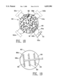
- FIG. 1 is an elevational schematic view of a tank with sludge at the bottom of the tank and hydrocarbons recovered by the invention at the top of the tank with outside sources for treatment.
- FIG. 2 is a detail view taken from FIG. 1 of microorganism action in recovering hydrocarbons from the sludge oil tank bottoms as the hydrocarbons migrate to the top of the treatment medium.
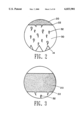
- FIG. 3 is a detail view of the floating hydrocarbon volume or level as it appears on top of the treatment medium, where the microbes continue to break down the hydrocarbons into a higher API gravity of oil.
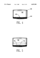
- FIG. 4 is a schematic view of a crude oil tank pumped to the lowest level with sludge at the bottom.
- FIG. 5 is a schematic view of the crude oil tank shown in FIG. 4 with treatment fluid added to the tank.
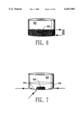
- FIG. 6 is a schematic view of the tank with sludge and a combination of treatment fluid, chemicals, biosurfactants, microorganisms, etc. heated and vigorously circulated.
- FIG. 7 is a view similar to FIG. 6 where the contents are vigorously circulated by directing fluid under pressure through lances toward the sludge at the bottom of the tank.
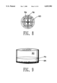
- FIG. 8 is a top schematic view of the invention which is similar to FIG. 7.
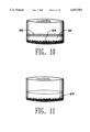
- FIG. 9 is a schematic view of the tank after labwork has indicted the heating and circulating should stop.
- FIG. 10 is a view of the tank similar to FIG. 9 after high temperature water has been injected to further separate recoverable hydrocarbons from the residual solids.
- FIG. 11 is a view of the tank after the volume of hydrocarbons are skimmed from the water.
- FIG. 12 is a schematic view of a tank with greatly reduced LEL levels where the worker using special recovery equipment can remove remaining deposits of sludge.
- FIG. 13 is a schematic view of a tank with a sump line.
- FIG. 14 is a schematic view of a tank having an existing opening.
- FIG. 15 is a schematic view of a tank having a floating roof with the present invention pumping fluids over the top of the tank.
- FIG. 16 is a perspective view of a lance connected through an opening to a tank.
- FIG. 17 is a top view of a lance connected through an opening to a tank.
- FIG. 17a is a perspective view of an inductor nozzle.
- FIG. 18 is a top view of a tank with four trucks having lines connected to existing openings to the tank and four lances which have been introduced into the tank through hot tapped openings.
- FIG. 19 is a top view of another embodiment of the invention.
- the hydrocarbon recovery process and system 10 includes the following procedures as implemented by one of ordinary skill in the art.
- One of ordinary skill in the art is generally a tank cleaning operator who has several years of experience in cleaning crude oil tanks 12. Coupled in this experience is the knowledge that every job and sludge is unique and lends itself to tweaking and combining various approaches to cleaning same.
- the next step is to determine the composition of the sludge, ie; salt, asphaltines, paraffins, rust and sand type solids. This will help an operator understand the volume and type of solids which will remain in the tank or vessel 12 at the completion of the process.
- Treatment dosages may be determined by altering microbes 32, chemical and surfactant concentrations, then monitoring the effects.
- the sludge samples are treated with various commercially available microorganism strains or they are treated with nutrients designed to enhance the development of natural microorganisms 32.
- a supplier of same such as Biosystems Corp. of Roscoe, Ill.; Gelman Sciences of Ann Arbor, Mich.; Bio-Technologies of Landisville, N.J.; Ecological Labs of Freeport, N.Y.: or Sybron Biochemical of Birmingham, N.J., notify them about the nature of the sludge and procedures to be used and request four to five different samples to test.
- the samples may contain microorganisms and/or bio-surfactants, either naturally occurring surface active compounds produced by micro-organisms 32 or of the synthesized type.
- the viscosity or grade of each sample is compared to the viscosity of an untreated sample over time.
- the sample showing the greatest percentage of viscosity change over time indicates the preferred treatment.
- the knowledge obtained from the lab work should now be applied in similar proportions in the field. Measurements referred to as parts per million or "PPM" refer to the sum total of sludge and fluid or chemical treatments. A detailed example follows which encompasses a broad range of various crude sludges.
- an aqueous treatment, water-based solution 30 (hereinafter referred to as "aqua-treat fluid") may comprise fresh or salt water.
- the "aqua-treat fluid" 30 should be introduced into the tank or vessel from the truck 50 at 90-150 degrees F. via a source 58.
- a tank or vessel 12 may have its own internal heat exchanger (heat cable 15 shown on outer diameter), or steam coil system 16.
- heat cable 15 shown on outer diameter heat cable 15 shown on outer diameter
- steam coil system 16 steam coil system 16.
- "aqua-treat fluid” 30 may be introduced at an ambient temperature and the temperature is then increased as the “aqua-treat fluid” 30 is circulated.
- the optimal temperature range may be determined by the preference of the particular bacteria 32 chosen.
- the "treatment fluid” 30 should contain approximately twenty parts per million nitrogen, a phosphorus level of at least five parts per million, and a neutral pH (adjusted if/as necessary) for the purpose of creating an environment which will stimulate the growth and reproduction of bacteria 32. These levels are to be used as a guideline, regardless of whether inoculating the system with microbes/bio-cultures and/or attempting to stimulate microbes naturally occurring in the system.
- the materials and ingredients ie: nitrogen, phosphorus and environmentally friendly pH adjusters are commercially available.
- the "aqua-treat fluid” 30 can be adjusted to meet these guidelines either while circulating or in treatment of "aqua-treat fluid" prior to introduction into tank 12.
- the system may also be aerated. Aeration is beneficial to bacteria which thrive in an oxygenated environment. Anaerobic bacteria, however, thrive where there is no free oxygen. A nitrogen perging system could be implemented in such a situation.
- the volume of aqua-treat fluid 30 is extracted from below level 22 (below the volume of floating hydrocarbon 20), moved through line 54, truck 50 via pump 52 and returned via line 56 into the same volume 30, or in cases where access through the bottom side 13 of the tank 12 is limited or when it may be desirable to cascade down the sides 17 to aerate the contents, returned above the level 22.
- sludge 40 has low levels of hydrocarbon contamination (generally, but not limited to, sludge having less than ten to fifteen percent hydrocarbons by volume), or hydrocarbons are negligible at the surface 24 of the tank 12, the circulated return fluids may be aerated at the circulating pump 52 or at the point of return 53, entering the tank 12 at optional points around the perimeter, encompassing the volume of floating hydrocarbons 20.
- Some tanks 12 have existing tank mixers 14. If tank mixers 14 are in place, these should be turned on at and for a determined time. This will enhance the circulation or dispersion of heat, bacteria 32, and nutrients.
- Biodegradable cleaning surfactants may also be used in conjunction with the above procedures as a part of the fluid treatment.
- Some examples of surfactants which may be used are BG-Clean-401, BG-Clean-406, BG-Clean-412, Bio-enhancer 850, and BG-Clean-715 Sludge Softener. All of these are commercially available from a manufacturer called Biogenesis located in Bismarck N.Dak. Each has instructions on recommended dosages which should be followed.
- Many commercially available biogradable surfactants and solvents contain their own proprietary mixture of bio-enhancement additives. Preferably, they should contain no petroleum derivatives, be non-toxic, ecologically safe and completely biodegradable.
- Naturally occurring bio-surfactants which result from micro-organism 32 activity/growth are beneficial to the desired result of optimizing hydrocarbon recovery and enhancing the specific gravity during the process of breaking down sludge oil 40.
- a microorganism supplier can be contacted in this regard.
- the addition of commercial surfactants also enhances the benefits of naturally occurring surfactants by making the surfactants effective in a shorter time span.
- phosphorus and pH levels are acceptable, one may proceed to inoculate the "aqua-treat fluid" with bacteria 32.
- the addition of microbial cultures, bio-surfactants and solvents, in combination or singly, is optional as a variable.
- composition of "aqua-treat fluids" 30 will vary from case to case.
- Several genera of bacteria 32 may be tested or used in the invention. Some common types, which may be used are PSEUDOMONAS, FLAVOBACTERIUM, ACINETOBACTER, AZOTOBACTER, KLEBSIELLA, ALCALIGENES, and RHIZOBIUM although other types are available and may be tested.
- the bacteria 32 possess complex metabolic schemes for utilization in bioremediation. Identification of all of the types of bacteria/microbes has been compared to the attempt of classifying all the insects in the world. This has not been done, and as the identification process is ongoing, new and useful adaptations of bacteria may be discovered and implemented into the present invention.
- volumes discussed relate to “total possible volume of the system", meaning the sum combination of “total sludge 40 volume” (after removal of all preexisting fluids from the tank 12), and the total volume of aqua treatment fluids 30 introduced to the system.
- the information outlined below relates to general rates for crude oil storage tanks 12 as oil is removed from oil wells, (defined as non-refined "crude oil”).
- Treatment fluid 30 dosages will vary according to the specific conditions of a tank 12 and with various goals in mind.
- tank bottoms or sludge oil 40 which is largely composed of asphaltines and/or heavy paraffin oils
- an oil used as a treatment fluid 30 may also contain any combination of bacteria 32 and/or nutrients (hereinafter referred to as "oil-treat fluid").
- the oil used can be #2 fuel oil, or any other similar high gravity hydrocarbon preferably having a low flash point, (which must always be considered when heating flammables) supplied by a storage vessel 57.
- the "oil-treat fluid” is used in conjunction with the “aqua-treat fluid” 30, with the “oil-treat fluid” the lessor in overall volume.
- the "oil-treat fluid” volume may be derived or separated from the beginning "sludge” 40, ranging from 20% (twenty percent) to 100% (one hundred percent) of the volume of the sludge 40.
- the "oil-treat fluid” may also be introduced as the first ingredient or during the "aqua-treat fluid” phase. Regardless, it is mentioned as an optional treatment procedure.
- the "aqua-treat fluid" volume 130 may need to be of a sufficient nature to facilitate floating the roof 118 off its supporting legs 119, insuring that any air pocket is unlikely to exist.
- a space may be created between the sludge 140 and the bottom of the roof 118. This space should be filled or replaced by the treatment fluid 130. Aeration would not likely be used in the case of a floating roof 118.
- a working example follows: a tank contains 50,000 (fifty thousand) barrels of crude oil. All "free” flowing oil is removed from the tank, leaving behind the "sludge oil", or “tank bottom”, which is 10,000 (ten thousand) barrels. This 10,000 (ten thousand) barrels is what is termed “total sludge volume”. After 12,000 (twelve thousand) barrels of "aqua-treat fluid”, and 5,000 (five thousand) barrels of "oil-treat fluid" are added, the “total volume of the system” is 27,000 (twenty seven thousand) barrels.
- the inoculation dosage (after nitrogen, phosphorus, and pH levels are optimal) one would refer to a supplier/manufacturers chart addressing the volume of the system, and read the culture dosage in pounds per barrel.
- the volume of the system being 27,000 (twenty seven thousand) barrels
- the suggested inoculation dosage would be one (1) pound per 600 (six hundred) barrels, which equates to 45 (forty five) pounds of actual microbial cultures introduced into the treatment fluids.
- tank 12 contents are heated and maintained in excess of ninety degrees Fahrenheit, by a steam coil 16, heat exchanger 15, hot oil truck/s 50, or other means or combinations thereof available to the operator.
- a steam coil 16 heat exchanger
- hot oil truck/s 50 hot oil truck/s 50, or other means or combinations thereof available to the operator.
- One purpose for the addition of heat is to stimulate the bacteria 32 and its growth.
- the sludge 40 should be monitored to update hydrocarbon levels in the sludge 40 by catching and analyzing a sample of the sludge 40.
- hydrocarbon level is determined to be low or non-existent (normally after about 7-21 days) tank mixers 14, heat sources 16, 50 and circulating pumps 52 can be shut off. However, the process is still incomplete.
- the operator checks the volume of the top oil 20. Regardless of the treatment fluid 30 used, the volume of top or floating oil 20 should be of a viscous nature by which an operator can manage its treatment.
- oil or an "oil-treat fluid" may be added as needed to create a volume of floating hydrocarbon 20 which is of value. If time is not an immediate concern, an operator may decide to let the "system” work by giving the microbes additional time to breakdown or treat the sludge 40. However an operator must normally consider time requirements. In some cases, where the aqueous volume is not a sufficient barrier between the tank bottoms 40 and the hydrocarbon level 22, then fresh or salt water can be introduced to raise the hydrocarbon level 22 and separate it from the tank bottoms 40.
- this water will insure a proper buffer and also aid in the removal of hydrocarbon from the solids remaining in the bottom of the tank 12 (it helps displace hydrocarbons from any solids, sand remaining in the bottom of the tank). It is preferable for this water to be hot and added in a volume which is in the range of twenty to fifty percent in excess of the volume of hydrocarbons remaining in the tank bottoms 40. This phase is complete when hydrocarbon "free” or near “free” solids exist (generally, but not limited to solids at the bottom of the tank 12 having less than 5% hydrocarbons by volume).
- the aqueous level is removed at the bottom of the tank 12 through a typical water draw system 55. When all liquids are removed, the tank hatch doors/manways may be removed.
- Land Farm--these solids 88 may be hydro-blasted to a common manway or hatch door and removed.
- Recycling--the solids 88 may be recycled to fuel blending, providing the material has a BTU value of 5,000 BTU/lb or greater.
- the introduction of coal fines has been successful in BTU enhancement or solidification for incinerator fuel.
- Solids 88 can be "squeegeed”, shoveled and transported to hatch doors or manways for removal. Adding water to move the solids will decrease dryness and the BTU value.
- 100% of the original "sludge oil" 40 is converted to three products: marketable crude oil, water and fuel. The procedure is now complete.
- a crude storage tank contained three feet of sludge oil. This sludge was a continuing problem for the operator. The oil from the tank was turned down by the buyer due to its poor quality. In addition sludge kept plugging the circulating suction pump. The sludge sample tested at 10% solids, 50% heavy asphaltines/paraffins, and 40% emulsified water.
- the present invention was implemented. Due to the high volume of hydrocarbon in the sludge, the "oil-treat fluid" was used.
- the medium chosen for the treatment fluid was forty gravity oil, supplied by the operator.
- the oil was introduced into the tank at a temperature greater than 90 degrees F., with natural nutrients and circulated at this temperature for 1 day, using a hot oil truck to heat and circulate the system. Pumps were then shut off.
- the tank was insulated and heat-taped so temperatures would remain constant for existing, natural microbial cultures to grow. After seven days the sludge volume was 60% depleted. After fourteen days only a small amount of sediment remained.
- the crude oil was returned to the heater and then to an oil sales tank for selling purposes. The remaining solids were suctioned through the recycle pump and deposited into a holding vessel. The resulting solids volume was not large enough to warrant further treatment and was landfarmed.
- a thirty-six inch pipe wrench was lowered into the tank on a rope, and could not penetrate any deeper than the oil sampler device.
- the tank was circulated with the equivalent of five feet of an aqua-treat fluid, organic cleaning compounds, and material for stimulating bacteria cultures.
- the aqua-treat fluid temperature was raised, by circulation through a heater truck, to an optimum temperature where the bacteria would colonize downward from the aqua-treat into the sludge.
- the aqua-treat fluid temperature was maintained by continual circulation of it through the heater truck. After twenty-one days the sludge volume was less than one foot, and the layer on top of the aqua-treat fluid had three feet of pumpable hydrocarbons. One foot of thirty-seven gravity crude was introduced with bacterial nutrients. Since time was not an immediate consideration for the operator, the tank was allowed to stand dormant for another twenty days.
- the top oil had an increase in specific gravity from 31.1 to 33.6 API and a 10% (ten percent) increase in solvent composition with a pour point reduction of twelve degrees from 115 deg. F. to 103 deg. F.
- a recycle pump transferred the resulting fluids to a three phase separator to divert the fluids to separate storage tanks and settle the solids.
- the water was hauled to a deep saltwater disposal well facility.
- the oil was sold as marketable crude.
- the solids were reduced from the sludge volume by 90% and land farmed.
- the process was successful in treating the sludge.
- Bacteria changed the chemical and physical properties of the sludge oil. Thinning and dilution agents resulted from solvents produced through their metabolic process. Bacteria breaks down long chain oil molecules into the short chain solvents. The resulting oil recovered from sludge has a higher gravity and a higher percentage of hydrocarbon recovery from the sludge or "tank bottoms" 40. No harmful chemicals were used in any part of this process.
- a tank 60 having sludge 62 on the bottom 64 will first have all of the existing fluids removed from the tank 60. Theses fluids are typically removed by pumping the fluids through an existing opening 61 (FIGS. 14 and 16) or by accessing the tank 60 over the top 65 (FIG. 15) of the tank 60 or through a hot tap.
- a volume of treatment fluid 70 e.g. cutter stock is added to the tank 60.
- the treatment fluid 70 should be waterbased.
- the sludge 62 is primarily oil based (as opposed to waterbased) normally a hydrocarbon based treatment fluid 70 should be used.
- the crude oil contained in the tank 60 may in certain situations have a high enough specific gravity to be used as a treatment fluid 70 in which case an operator leaves the preexisting crude oil in the tank 60 to be used as the treatment fluid 70.
- Some examples of commonly used treatment fluid 70 are water, brine, number two diesel fuel, VGO (Virgin Gas Oil) and crude oil.
- An oil based treatment fluid 70 should have shorter hydrocarbon chains than hydrocarbon chains in the sludge 62.
- the shorter hydrocarbon chains will cut or fluidize the longer chains. This enables solids to settle out of the sludge 62, promotes hydrocarbon separation, and decreases the viscosity of the hydrocarbons.
- the next step is to add thermal and mechanical energy to the contents 80 (contents 80 includes sludge 62 mixed with treatment fluid 70) in the tank 60.
- contents 80 includes sludge 62 mixed with treatment fluid 70
- the lab work may suggest to the operator to add chemicals, biosurfactants, microbes, enzymes or a combination thereof as previously described.
- Mild agitation may be added to the tank 60 by the existing tank mixer 14 (FIG. 1) to swirl the contents 80.
- HYDROCARBON SHEARING The sludge 62 in the tank 60 normally comprises crude oil, dirt, water and rust which builds upon itself and clings together. Vigorous mechanical energy or agitation can be used to force apart this mixture.
- One of the major advantages of this invention is that the entire separation process takes place in the tank 60 itself as opposed to prior systems where the contents are removed from the tank 60 and treated outside the tank 60.
- the sump drain line 63 (FIG. 13) (A sump drain line 63 is a line which terminates in a sump 63a below the bottom level 64 of the tank 60b), is used as a suction or feed line to the circulation pumps for adding thermal and/or mechanical energy to tank contents 80.
- an operator can create additional openings 61 to the tank 60 by a hot tap.
- An operator normally adds between one and eight openings 61 to the tank 60 depending on the nature of the sludge to be treated and the size of the tank. However, more openings 61 aid in the agitation of the sludge 62 and contents 80. Therefor in certain situations where there are four existing openings to the tank 60, the operator may hot tap, for example, four additional openings to the tank 60.
- a device for example, one may access the tank 60 by introducing lances 66 (FIGS. 7, 16 and 18) through the openings 61.
- a stuffing box 67 and valve 68 are part of the connection between the tank 60 and the lances 66. The connection enables the operator to move the lances 66 in and out, at various angles between the tank sidewall 69 and the lance 66 to enhance the ability to agitate the contents 80.
- the truck 50 will pump a portion of the contents through line 54 to the truck 50.
- the truck 50 then heats the treatment fluid and pumps it back to the tank by a return line 56.
- the contents 80 may be filtered by any common, known means before reintroduction into the tank 60.
- the lances 66 direct the treatment fluid 80 back into the tank 60 at pressures up to and exceeding 2,000 psi although the pressures are generally in the range of 500-1500 PSI and a pressure of 1800 PSI is presently preferred. As best shown in FIG. 7, it may be desirable to direct the lances 66 toward or along the bottom level 64 of the tank 60 to break up and expose the sludge 62 compacted on the bottom 64 of the tank 60.
- the pumps 52 to be used in the system should be capable of pumping in the range of one to twenty barrels per minute and at pressures in the range of 500 to 3,000 psi.
- FIG. 8 show the lines of force 78 created by four lances 66 and waves 79 created by the force within the tank 60.
- the truck 50 may have heating coils (not shown) with thermal energy supplied by a propane burner.
- Other types of heaters could also be used, such as for example a steam heat exchanger.
- Some tanks have existing heating devices which could be placed in service to heat the tank contents.
- a hose 66a may be added on to the end 66b of each lance 66.
- the hose 66a may be about 2 1/2 feet in length although the length can vary according to the size of the tank 60.
- the hose 66a further aids in the effort to mix/agitate the contents 80 including the sludge 62 in the tank 60 due to a "whipping" action created by forcing the treatment fluid 70 or contents 80 under pressure through the hose 66a and the forces of the swirling contents 80 impinging on the outside of the hose 66a.
- a nozzle 66c such as an inductor nozzle (FIG. 17A) may be added to the end of each hose 66a to further aid in increasing the pressure at which the fluid is sprayed or reintroduced to the tank 60.
- a single access or opening 61 may be used to introduce the heated treatment fluid 70 under pressure to the tank 60 through a main pipe 90 located proximate the bottom 64 of the tank 60.
- a series of branch pipes 92, 93, 94 extending across the tank 60 are connected to the main pipe 90.
- Each branch pipe 92, 93, 94 has a series of nozzles 66c and/or "whip" hoses 66a attached to the main pipe 90 (e.g. one hose nozzle 66c every one foot along the length of a branch pipe 92, 93, 94).
- the hose 66a and nozzle 66c will preferably extend downward in the tank 60 to direct the pressurized fluid 70 toward the sludge on the bottom of the tank 60 to agitate same.
- the pumps 52 can be shut down to allow a sample to be taken from the tank 60 after the contents settle. Samples may be taken at all levels (e.g. top, middle and bottom) of tank 60 with common sampling equipment (not shown) like the eighteen inch W. L. Walker Model A-70002. Additional lab work can be preformed on the sample in order to determine the amount of progress which has been made. The next step or action to be taken by the operator will be dictated in part by the results of the sample i.e. material separation. If the progress is slow an experienced operator will consider available options such as treating for additional time, changing the cutter stock, adding microbes, surfactants, etc.
- the lances 66 may be removed from the tank 60.
- a volume of separating or displacement fluid 85 having a greater specific gravity than the hydrocarbons such as high temperature water or brine as described above should be added to the tank 60 to separate the hydrocarbons from the bottoms and to separate the hydrocarbons into a layer or volume 86 for removal and recovery of these hydrocarbons.
- the hydrocarbons and the separating fluid 85 are removed from the tank 60.
- the operator uses techniques commonly known in the industry (FIG. 12) for removing the contents 88 remaining at the bottom of the tank 60. Such techniques include steam lancing, air moving, shoveling, etc.
Abstract
Description
______________________________________
                             BIO-
                             DEGRADABLE
VOLUME OF TOT.               CLEANERS/
SYSTEM IN BARRELS
               INOCULATION   BIO-
(42 U.S. GALLONS EACH)
               CULTURE DOSAGE
                             SURFACTANTS
______________________________________
  250-1,200 BBLS
               1 LB/120 BBLS 1 GAL/ 30 BBLS
 1,200-7,200 BBLS
               1 LB/240 BBLS 1 GAL/ 60 BBLS
7,200-24,000 BBLS
               1 LB/480 BBLS 1 GAL/100 BBLS
    24,000+ BBLS
               1 LB/600 BBLS 1 GAL/130 BBLS
______________________________________
Claims (14)
Priority Applications (1)
| Application Number | Priority Date | Filing Date | Title |
|---|---|---|---|
| US09/271,949 US6033901A (en) | 1994-04-11 | 1999-03-18 | System and process for in tank treatment of crude oil sludges to recover hydrocarbons and aid in materials separation |
Applications Claiming Priority (3)
| Application Number | Priority Date | Filing Date | Title |
|---|---|---|---|
| US22887794A | 1994-04-11 | 1994-04-11 | |
| US08/885,108 US6069002A (en) | 1994-04-11 | 1997-06-30 | System and process for in tank treatment of crude oil sludges to recover hydrocarbons and aid in materials separation |
| US09/271,949 US6033901A (en) | 1994-04-11 | 1999-03-18 | System and process for in tank treatment of crude oil sludges to recover hydrocarbons and aid in materials separation |
Related Parent Applications (1)
| Application Number | Title | Priority Date | Filing Date |
|---|---|---|---|
| US08/885,108 Continuation US6069002A (en) | 1994-04-11 | 1997-06-30 | System and process for in tank treatment of crude oil sludges to recover hydrocarbons and aid in materials separation |
Publications (1)
| Publication Number | Publication Date |
|---|---|
| US6033901A true US6033901A (en) | 2000-03-07 |
Family
ID=25386153
Family Applications (2)
| Application Number | Title | Priority Date | Filing Date |
|---|---|---|---|
| US08/885,108 Expired - Lifetime US6069002A (en) | 1994-04-11 | 1997-06-30 | System and process for in tank treatment of crude oil sludges to recover hydrocarbons and aid in materials separation |
| US09/271,949 Expired - Lifetime US6033901A (en) | 1994-04-11 | 1999-03-18 | System and process for in tank treatment of crude oil sludges to recover hydrocarbons and aid in materials separation |
Family Applications Before (1)
| Application Number | Title | Priority Date | Filing Date |
|---|---|---|---|
| US08/885,108 Expired - Lifetime US6069002A (en) | 1994-04-11 | 1997-06-30 | System and process for in tank treatment of crude oil sludges to recover hydrocarbons and aid in materials separation |
Country Status (5)
| Country | Link |
|---|---|
| US (2) | US6069002A (en) |
| AR (1) | AR013150A1 (en) |
| AU (1) | AU8271598A (en) |
| CA (1) | CA2295723A1 (en) |
| WO (1) | WO1999000544A1 (en) |
Cited By (31)
| Publication number | Priority date | Publication date | Assignee | Title |
|---|---|---|---|---|
| US6443166B1 (en) * | 2000-10-12 | 2002-09-03 | General Electric Company | Method of cleaning a pressurized container |
| US6532684B1 (en) | 2000-10-12 | 2003-03-18 | General Electric Company | System for cleaning pressurized containers |
| US6539961B1 (en) | 2000-10-12 | 2003-04-01 | General Electric Company | System for cleaning pressurized containers such as mobile railcars |
| US6635119B1 (en) | 2000-10-12 | 2003-10-21 | General Electric Company | Method of cleaning pressurized containers containing liquified petroleum gas |
| US6758913B1 (en) | 2000-10-12 | 2004-07-06 | General Electric Company | Method of cleaning pressurized containers containing anhydrous ammonia |
| US6793740B1 (en) | 2000-10-12 | 2004-09-21 | General Electric Company | Method for cleaning pressurized containers containing moisture sensitive chemicals |
| KR100475172B1 (en) * | 2001-02-20 | 2005-03-08 | 에스케이 주식회사 | Method for Removing Sludges in A Crude Oil Tank and Recovering Oil Therefrom |
| US6926776B1 (en) | 2000-10-12 | 2005-08-09 | General Electric Company | Method for cleaning pressurized containers containing chlorine gas or sulfur dioxide gas |
| US20100051444A1 (en) * | 2005-12-16 | 2010-03-04 | Zaikin Yuriy A | Self-sustaining cracking of hydrocarbons |
| US20130083620A1 (en) * | 2011-09-29 | 2013-04-04 | Ronald D. Hypes | Interface and Mud Control System and Method for Refinery Desalters |
| US20140042107A1 (en) * | 2012-08-07 | 2014-02-13 | John E. Powell | Nozzled Confined Container for Treating Sludge |
| US20160158669A1 (en) * | 2011-09-29 | 2016-06-09 | Cameron International Corporation | Interface And Mud Control System And Method For Refinery Desalters |
| US9550937B2 (en) | 2014-07-31 | 2017-01-24 | Baker Hughes Incorporated | Methods and compositions for decreasing the viscosity of hydrocarbon-based fluids during refining |
| US20170174424A1 (en) * | 2012-04-26 | 2017-06-22 | Michael Henry James | Apparatus For Cleaning The Interior Of An Above Ground Storage Tank |
| WO2018148397A3 (en) * | 2017-02-09 | 2018-11-01 | Locus Oil Ip Company, Llc | Compositions and methods for reducing hydrogen sulfide and microbial influenced corrosion in crude oil, natural gas, and in associated equipment |
| US10576519B2 (en) | 2015-09-10 | 2020-03-03 | Locus Oil Ip Company, Llc | Enhanced microbial production of biosurfactants and other products, and uses thereof |
| US10584044B2 (en) * | 2016-03-15 | 2020-03-10 | Amperage Energy Inc. | System and method for removing iron from waste water |
| US10907106B2 (en) | 2017-06-21 | 2021-02-02 | Locus Oil Ip Company, Llc | Treatment for upgrading heavy crude oil |
| US10947444B2 (en) | 2017-02-07 | 2021-03-16 | Locus Oil Ip Company, Llc | Materials and methods for reducing viscosity of oil |
| US11396623B2 (en) | 2017-09-27 | 2022-07-26 | Locus Oil Ip Company, Llc | Materials and methods for recovering oil from oil sands |
| US11401452B2 (en) | 2017-07-27 | 2022-08-02 | Locus Oil Ip Company, Llc | Methods of selective and non-selective plugging for water flooding in enhanced oil recovery |
| US11434415B2 (en) | 2018-04-30 | 2022-09-06 | Locus Oil Ip Company, Llc | Compositions and methods for paraffin liquefaction and enhanced oil recovery in oil wells and associated equipment |
| US11447684B2 (en) | 2018-08-20 | 2022-09-20 | Locus Oil Ip Company, Llc | Methods for paraffin removal and extended post-primary oil recovery |
| US11549052B2 (en) | 2017-11-08 | 2023-01-10 | Locus Solutions Ipco, Llc | Multifunctional composition for enhanced oil recovery, improved oil quality and prevention of corrosion |
| US11549053B2 (en) | 2018-07-30 | 2023-01-10 | Locus Solutions Ipco, Llc | Compositions and methods for enhanced oil recovery from low permeability formations |
| US11549067B2 (en) | 2017-06-12 | 2023-01-10 | Locus Solutions Ipco, Llc | Remediation of rag layer and other disposable layers in oil tanks and storage equipment |
| US11608465B2 (en) | 2018-03-27 | 2023-03-21 | Locus Solutions Ipco, Llc | Multi-functional compositions for enhanced oil and gas recovery and other petroleum industry applications |
| US11760969B2 (en) | 2016-09-08 | 2023-09-19 | Locus Solutions Ipco, Llc | Distributed systems for the efficient production and use of microbe-based compositions |
| US11788034B2 (en) | 2017-04-09 | 2023-10-17 | Locus Solutions Ipco, Llc | Materials and methods for maintaining industrial, mechanical and restaurant equipment |
| US11834705B2 (en) | 2016-12-11 | 2023-12-05 | Locus Solutions Ipco, Llc | Microbial products and their use in bioremediation and to remove paraffin and other contaminating substances from oil and gas production and processing equipment |
| US11959062B2 (en) | 2023-08-10 | 2024-04-16 | Locus Solutions Ipco, Llc | Distributed systems for the efficient production and use of microbe-based compositions |
Families Citing this family (16)
| Publication number | Priority date | Publication date | Assignee | Title |
|---|---|---|---|---|
| US6571810B1 (en) * | 1994-09-30 | 2003-06-03 | Zymo International, Inc. | Parts washing system |
| GB2358791A (en) * | 2000-02-04 | 2001-08-08 | Versar Inc | Method composition and apparatus for cleaning internal surfaces of oxygen converters and cylinders |
| CN1500132A (en) * | 2000-11-17 | 2004-05-26 | Microbial-induced controllable cracking of normal and branched alkanes in oils | |
| EP1427547A1 (en) * | 2001-02-07 | 2004-06-16 | Idrabel Italia S.r.l. | A biotechnological method for the regeneration of hydrocarbons from dregs and muds, on the base of biosurfactants |
| CA2441969C (en) * | 2002-11-06 | 2010-09-28 | Larry Saik | A trailer mounted mobile apparatus for dewatering and recovering formation sand |
| US20060037919A1 (en) * | 2004-08-18 | 2006-02-23 | Agustin Lara | Diesel fuel filter and associated methods |
| EP1881946B1 (en) * | 2005-05-19 | 2012-11-21 | M-I L.L.C. | Oil-based sludge separation and treatment system |
| US20070283981A1 (en) * | 2006-06-08 | 2007-12-13 | Stewart Tracy E | Method for cleaning storage tanks |
| US20110126862A1 (en) * | 2007-03-20 | 2011-06-02 | Idrabel Italia S.R.L. | Method and Plant for Treating Bottom Sludge in a Tank |
| WO2009055836A1 (en) * | 2007-11-02 | 2009-05-07 | Leighton O'brien Pty. Ltd. | Fuel and fuel tank treatment |
| US8491721B2 (en) * | 2008-08-14 | 2013-07-23 | International Technologies And Services, Inc. | Method of cleaning and degassing a storage vessel |
| US8984709B1 (en) * | 2011-10-25 | 2015-03-24 | John K. Rollins | No-entry bulk oil storage tank cleaning system |
| MY174488A (en) | 2012-04-20 | 2020-04-22 | Bci Sabah Int Petroleum Sdn Bhd | A method of removing oil sludge and recovering oil from oil sludge with nanoemulsion surfactant system |
| SE537220C2 (en) * | 2013-05-06 | 2015-03-03 | Gaftec Ab | Method and system for internal washing of the cistern |
| US9868924B1 (en) | 2014-06-02 | 2018-01-16 | International Technologies And Services, Inc. | Composition and method |
| US10184087B2 (en) * | 2016-01-04 | 2019-01-22 | TriStar PetroServ, Inc. | Optimization of a method for isolation of paraffinic hydrocarbons |
Citations (3)
| Publication number | Priority date | Publication date | Assignee | Title |
|---|---|---|---|---|
| US4364776A (en) * | 1980-01-19 | 1982-12-21 | Emultec Limited | Recovery of heavy hydrocarbons from oil sludge |
| US4474622A (en) * | 1980-12-23 | 1984-10-02 | Establissements Somalor-Ferrari Somafer S.A. | Composition and process for recovering and upgrading petroleum products |
| US4897205A (en) * | 1987-09-21 | 1990-01-30 | Landry Service Co., Inc. | Method for treating waste material |
Family Cites Families (8)
| Publication number | Priority date | Publication date | Assignee | Title |
|---|---|---|---|---|
| US3769164A (en) * | 1970-06-03 | 1973-10-30 | Bioteknika International | Microbial degradation of petroleum |
| US4153553A (en) * | 1977-09-29 | 1979-05-08 | Davis Larry R | Apparatus for and method of reclaiming and cleaning oil from bottom settlings of tanks |
| US4276094A (en) * | 1979-02-22 | 1981-06-30 | Biotechnologie Aktiengesellschaft Fur Emulsan | Cleaning oil-contaminated vessels with α-emulsans |
| US5085710A (en) * | 1989-10-31 | 1992-02-04 | Nalco Chemical Company | Method of using an aqueous chemical system to recover hydrocarbon and minimize wastes from sludge deposits in oil storage tanks |
| US5271851A (en) * | 1993-03-08 | 1993-12-21 | Kerr-Mcgee Corporation | Integrated treatment system for refinery oily sludges |
| BR9304238A (en) * | 1993-10-15 | 1995-06-06 | Petroleo Brasileiro Sa | Thermo-chemical cleaning of storage tanks |
| US5611869A (en) * | 1995-10-25 | 1997-03-18 | Betzdearborn Inc. | Refinery vessel cleaning treatment |
| US5653865A (en) * | 1995-11-06 | 1997-08-05 | Miyasaki; Mace T. | Method and apparatus for recovering the fuel value of crude oil sludge |
-
1997
- 1997-06-30 US US08/885,108 patent/US6069002A/en not_active Expired - Lifetime
-
1998
- 1998-06-29 AU AU82715/98A patent/AU8271598A/en not_active Abandoned
- 1998-06-29 CA CA002295723A patent/CA2295723A1/en not_active Abandoned
- 1998-06-29 WO PCT/US1998/013448 patent/WO1999000544A1/en active Application Filing
- 1998-06-30 AR ARP980103166A patent/AR013150A1/en unknown
-
1999
- 1999-03-18 US US09/271,949 patent/US6033901A/en not_active Expired - Lifetime
Patent Citations (3)
| Publication number | Priority date | Publication date | Assignee | Title |
|---|---|---|---|---|
| US4364776A (en) * | 1980-01-19 | 1982-12-21 | Emultec Limited | Recovery of heavy hydrocarbons from oil sludge |
| US4474622A (en) * | 1980-12-23 | 1984-10-02 | Establissements Somalor-Ferrari Somafer S.A. | Composition and process for recovering and upgrading petroleum products |
| US4897205A (en) * | 1987-09-21 | 1990-01-30 | Landry Service Co., Inc. | Method for treating waste material |
Cited By (43)
| Publication number | Priority date | Publication date | Assignee | Title |
|---|---|---|---|---|
| US6443166B1 (en) * | 2000-10-12 | 2002-09-03 | General Electric Company | Method of cleaning a pressurized container |
| US6532684B1 (en) | 2000-10-12 | 2003-03-18 | General Electric Company | System for cleaning pressurized containers |
| US6539961B1 (en) | 2000-10-12 | 2003-04-01 | General Electric Company | System for cleaning pressurized containers such as mobile railcars |
| US6635119B1 (en) | 2000-10-12 | 2003-10-21 | General Electric Company | Method of cleaning pressurized containers containing liquified petroleum gas |
| US6758913B1 (en) | 2000-10-12 | 2004-07-06 | General Electric Company | Method of cleaning pressurized containers containing anhydrous ammonia |
| US6793740B1 (en) | 2000-10-12 | 2004-09-21 | General Electric Company | Method for cleaning pressurized containers containing moisture sensitive chemicals |
| US6926776B1 (en) | 2000-10-12 | 2005-08-09 | General Electric Company | Method for cleaning pressurized containers containing chlorine gas or sulfur dioxide gas |
| KR100475172B1 (en) * | 2001-02-20 | 2005-03-08 | 에스케이 주식회사 | Method for Removing Sludges in A Crude Oil Tank and Recovering Oil Therefrom |
| US20100051444A1 (en) * | 2005-12-16 | 2010-03-04 | Zaikin Yuriy A | Self-sustaining cracking of hydrocarbons |
| US8192591B2 (en) | 2005-12-16 | 2012-06-05 | Petrobeam, Inc. | Self-sustaining cracking of hydrocarbons |
| US8911617B2 (en) | 2005-12-16 | 2014-12-16 | Petrobeam, Inc. | Self-sustaining cracking of hydrocarbons |
| US20130083620A1 (en) * | 2011-09-29 | 2013-04-04 | Ronald D. Hypes | Interface and Mud Control System and Method for Refinery Desalters |
| US9115316B2 (en) * | 2011-09-29 | 2015-08-25 | Cameron International Corporation | Interface and mud control system and method for refinery desalters |
| US20160158669A1 (en) * | 2011-09-29 | 2016-06-09 | Cameron International Corporation | Interface And Mud Control System And Method For Refinery Desalters |
| US9751027B2 (en) * | 2011-09-29 | 2017-09-05 | Cameron International Corporation | Interface and mud control system and method for refinery desalters |
| US20170174424A1 (en) * | 2012-04-26 | 2017-06-22 | Michael Henry James | Apparatus For Cleaning The Interior Of An Above Ground Storage Tank |
| US10710796B2 (en) * | 2012-04-26 | 2020-07-14 | Michael Henry James | Apparatus for cleaning the interior of an above ground storage tank |
| US20140042107A1 (en) * | 2012-08-07 | 2014-02-13 | John E. Powell | Nozzled Confined Container for Treating Sludge |
| US9550937B2 (en) | 2014-07-31 | 2017-01-24 | Baker Hughes Incorporated | Methods and compositions for decreasing the viscosity of hydrocarbon-based fluids during refining |
| US10576519B2 (en) | 2015-09-10 | 2020-03-03 | Locus Oil Ip Company, Llc | Enhanced microbial production of biosurfactants and other products, and uses thereof |
| US11890657B2 (en) | 2015-09-10 | 2024-02-06 | Locus Solutions Ipco, Llc | Enhanced microbial production of biosurfactants and other products, and uses thereof |
| US10584044B2 (en) * | 2016-03-15 | 2020-03-10 | Amperage Energy Inc. | System and method for removing iron from waste water |
| US11760969B2 (en) | 2016-09-08 | 2023-09-19 | Locus Solutions Ipco, Llc | Distributed systems for the efficient production and use of microbe-based compositions |
| US11834705B2 (en) | 2016-12-11 | 2023-12-05 | Locus Solutions Ipco, Llc | Microbial products and their use in bioremediation and to remove paraffin and other contaminating substances from oil and gas production and processing equipment |
| US10947444B2 (en) | 2017-02-07 | 2021-03-16 | Locus Oil Ip Company, Llc | Materials and methods for reducing viscosity of oil |
| US11479711B2 (en) | 2017-02-07 | 2022-10-25 | Locus Oil Ip Company, Llc | Materials and methods for reducing viscosity of oil |
| WO2018148397A3 (en) * | 2017-02-09 | 2018-11-01 | Locus Oil Ip Company, Llc | Compositions and methods for reducing hydrogen sulfide and microbial influenced corrosion in crude oil, natural gas, and in associated equipment |
| US11155746B2 (en) | 2017-02-09 | 2021-10-26 | Locus Oil Ip Company, Llc | Compositions and methods for reducing hydrogen sulfide and microbial influenced corrosion in crude oil, natural gas, and in associated equipment |
| CN110462001A (en) * | 2017-02-09 | 2019-11-15 | 轨迹石油Ip有限责任公司 | For mitigating the composition and method of the hydrogen sulfide in crude oil, natural gas and relevant device and microbiologic(al) corrosion |
| US11788034B2 (en) | 2017-04-09 | 2023-10-17 | Locus Solutions Ipco, Llc | Materials and methods for maintaining industrial, mechanical and restaurant equipment |
| US11920091B2 (en) | 2017-06-12 | 2024-03-05 | Locus Solutions Ipco, Llc | Remediation of rag layer and other disposable layers in oil tanks and storage equipment |
| US11549067B2 (en) | 2017-06-12 | 2023-01-10 | Locus Solutions Ipco, Llc | Remediation of rag layer and other disposable layers in oil tanks and storage equipment |
| US11441082B2 (en) | 2017-06-21 | 2022-09-13 | Locus Oil Ip Company, Llc | Treatment for upgrading heavy crude oil |
| US10907106B2 (en) | 2017-06-21 | 2021-02-02 | Locus Oil Ip Company, Llc | Treatment for upgrading heavy crude oil |
| US11401452B2 (en) | 2017-07-27 | 2022-08-02 | Locus Oil Ip Company, Llc | Methods of selective and non-selective plugging for water flooding in enhanced oil recovery |
| US11396623B2 (en) | 2017-09-27 | 2022-07-26 | Locus Oil Ip Company, Llc | Materials and methods for recovering oil from oil sands |
| US11549052B2 (en) | 2017-11-08 | 2023-01-10 | Locus Solutions Ipco, Llc | Multifunctional composition for enhanced oil recovery, improved oil quality and prevention of corrosion |
| US11608465B2 (en) | 2018-03-27 | 2023-03-21 | Locus Solutions Ipco, Llc | Multi-functional compositions for enhanced oil and gas recovery and other petroleum industry applications |
| US11891567B2 (en) | 2018-04-30 | 2024-02-06 | Locus Solutions Ipco, Llc | Compositions and methods for paraffin liquefaction and enhanced oil recovery in oil wells and associated equipment |
| US11434415B2 (en) | 2018-04-30 | 2022-09-06 | Locus Oil Ip Company, Llc | Compositions and methods for paraffin liquefaction and enhanced oil recovery in oil wells and associated equipment |
| US11549053B2 (en) | 2018-07-30 | 2023-01-10 | Locus Solutions Ipco, Llc | Compositions and methods for enhanced oil recovery from low permeability formations |
| US11447684B2 (en) | 2018-08-20 | 2022-09-20 | Locus Oil Ip Company, Llc | Methods for paraffin removal and extended post-primary oil recovery |
| US11959062B2 (en) | 2023-08-10 | 2024-04-16 | Locus Solutions Ipco, Llc | Distributed systems for the efficient production and use of microbe-based compositions |
Also Published As
| Publication number | Publication date |
|---|---|
| US6069002A (en) | 2000-05-30 |
| CA2295723A1 (en) | 1999-01-07 |
| WO1999000544A1 (en) | 1999-01-07 |
| AR013150A1 (en) | 2000-12-13 |
| AU8271598A (en) | 1999-01-19 |
Similar Documents
| Publication | Publication Date | Title |
|---|---|---|
| US6033901A (en) | System and process for in tank treatment of crude oil sludges to recover hydrocarbons and aid in materials separation | |
| Banat et al. | Biosurfactant production and use in oil tank clean-up | |
| De Almeida et al. | Biosurfactants: promising molecules for petroleum biotechnology advances | |
| Atlas et al. | Stimulated petroleum biodegradation | |
| Perfumo et al. | Possibilities and challenges for biosurfactants use in petroleum industry | |
| EP0748860B1 (en) | Demulsification by microorganisms | |
| RU2169752C2 (en) | Cleaning composition, method for cleaning oil and gas wells, pipelines, casing tubes, and productive formations, method for removing excessive water, sediments, or both from produced crude oil, and method for hydraulic breakdown of formation | |
| US7449429B2 (en) | System for treating petroleum and petrochemical slop oil and sludge wastes | |
| US5622864A (en) | Apparatus for remediating contaminated soil containing organic compounds | |
| US5225083A (en) | Method for bioremediation of grease traps | |
| CN101379009A (en) | Apparatus and process for separation of organic materials from attached insoluble solids, and conversion into useful products | |
| CN1325404C (en) | Harmless oil field mud and sand treating method and apparatus | |
| CA2018622A1 (en) | Fixed bed bioreactor remediation system | |
| WO2008106371A2 (en) | Integrated cogeneration wastewater sewage and waste polar fats/ oils/ greases/waxes (fog) waste treatment method and facility | |
| WO2019204715A1 (en) | Compositions and methods for removing sludge from oil storage tanks | |
| NL8002289A (en) | METHOD AND APPARATUS FOR RECOVERING HEAVY HYDROCARBONS FROM OIL SLUDGE | |
| CN105967343A (en) | Compound biological enzyme preparation, compound microbial agent and application thereof in treatment of oily sludge | |
| US5911541A (en) | Thin layer solvent extraction | |
| WO2007093993A2 (en) | Microbial compositions useful for the degradation of hydrocarbons | |
| CN205362140U (en) | Oil tank washing system | |
| RU2698667C1 (en) | Method for processing oil-containing sludge and technological complex for its implementation | |
| US5545801A (en) | Wand inductor for remediation of contaminated soil | |
| CN105436162A (en) | Oil tank cleaning system | |
| MXPA00000491A (en) | System and process for in tank treatment of crude oil sludges | |
| RU2704654C1 (en) | Method of oil sludge utilization |
Legal Events
| Date | Code | Title | Description |
|---|---|---|---|
| STCF | Information on status: patent grant |
Free format text: PATENTED CASE |
|
| FPAY | Fee payment |
Year of fee payment: 4 |
|
| AS | Assignment |
Owner name: HIGH RIVER LIMITED PARTNERSHIP, NEW YORK Free format text: SECURITY INTEREST;ASSIGNOR:PHILIP SERVICES CORPORATION;REEL/FRAME:014601/0007 Effective date: 20031231 |
|
| AS | Assignment |
Owner name: UBS AG STAMFORD BRANCH, AS AGENT, CONNECTICUT Free format text: SECURITY AGREEMENT;ASSIGNORS:PHILIP SERVICES CORPORATION;ALLWASTE TANK CLEANING, INC.;NORTHLAND ENVIRONMENTAL, INC.;AND OTHERS;REEL/FRAME:015596/0014 Effective date: 20041230 Owner name: BANK OF AMERICA, N.A., AS AGENT, TEXAS Free format text: SECURITY AGREEMENT;ASSIGNORS:PHILIP SERVICES CORPORATION;ALLWASTE TANK CLEANING, INC.;NORTHLAND ENVIRONMENTAL, INC.;AND OTHERS;REEL/FRAME:015596/0014 Effective date: 20041230 |
|
| AS | Assignment |
Owner name: PHILIP SERVICES CORPORATION, TEXAS Free format text: TERMINATION OF SECURITY INTEREST;ASSIGNORS:HIGH RIVER LIMITED PARTNERSHIP, AS EXIT LOAN COLLATERAL AGENT;HIGH RIVER LIMITED PARTNERSHIP, AS PIK/TERM COLLATERAL AGENT;REEL/FRAME:017718/0948 Effective date: 20041230 |
|
| FPAY | Fee payment |
Year of fee payment: 8 |
|
| AS | Assignment |
Owner name: UBS AG, STAMFORD BRANCH, AS AGENT, CONNECTICUT Free format text: AMENDED & RESTATED PATENT SECURITY AGREEMENT;ASSIGNORS:PSC, LLC;BURLINGTON ENVIRONMENTAL, LLC;NORTHLAND ENVIRONMENTAL, LLC;AND OTHERS;REEL/FRAME:022562/0110 Effective date: 20090403 Owner name: BANK OF AMERICA, N.A., AS AGENT, TEXAS Free format text: AMENDED & RESTATED PATENT SECURITY AGREEMENT;ASSIGNORS:PSC, LLC;BURLINGTON ENVIRONMENTAL, LLC;NORTHLAND ENVIRONMENTAL, LLC;AND OTHERS;REEL/FRAME:022562/0110 Effective date: 20090403 |
|
| AS | Assignment |
Owner name: PSC INDUSTRIAL OUTSOURCING, LP, TEXAS Free format text: MERGER;ASSIGNOR:APLC, INC.;REEL/FRAME:024723/0838 Effective date: 20100723 |
|
| AS | Assignment |
Owner name: BURLINGTON ENVIRONMENTAL, LLC, TEXAS Free format text: TERMINATION AND RELEASE OF AMENDED AND RESTATED PATENT SECURITY AGREEMENT;ASSIGNORS:UBS AG, STAMFORD BRANCH;BANK OF AMERICA, N.A.;REEL/FRAME:024776/0797 Effective date: 20100730 Owner name: PSC, LLC, TEXAS Free format text: TERMINATION AND RELEASE OF AMENDED AND RESTATED PATENT SECURITY AGREEMENT;ASSIGNORS:UBS AG, STAMFORD BRANCH;BANK OF AMERICA, N.A.;REEL/FRAME:024776/0797 Effective date: 20100730 Owner name: PSC INDUSTRIAL OUTSOURCING, LP, TEXAS Free format text: TERMINATION AND RELEASE OF AMENDED AND RESTATED PATENT SECURITY AGREEMENT;ASSIGNORS:UBS AG, STAMFORD BRANCH;BANK OF AMERICA, N.A.;REEL/FRAME:024776/0797 Effective date: 20100730 Owner name: NORTHLAND ENVIRONMENTAL, LLC, TEXAS Free format text: TERMINATION AND RELEASE OF AMENDED AND RESTATED PATENT SECURITY AGREEMENT;ASSIGNORS:UBS AG, STAMFORD BRANCH;BANK OF AMERICA, N.A.;REEL/FRAME:024776/0797 Effective date: 20100730 Owner name: NORTRU, LLC, TEXAS Free format text: TERMINATION AND RELEASE OF AMENDED AND RESTATED PATENT SECURITY AGREEMENT;ASSIGNORS:UBS AG, STAMFORD BRANCH;BANK OF AMERICA, N.A.;REEL/FRAME:024776/0797 Effective date: 20100730 |
|
| AS | Assignment |
Owner name: ROYAL BANK OF CANADA, CANADA Free format text: SECURITY AGREEMENT;ASSIGNORS:BURLINGTON ENVIRONMENTAL, LLC;NORTRU, LLC;PSC, LLC;AND OTHERS;REEL/FRAME:024785/0232 Effective date: 20100730 |
|
| FPAY | Fee payment |
Year of fee payment: 12 |
|
| AS | Assignment |
Owner name: PSC INDUSTRIAL OUTSOURCING, LP, TEXAS Free format text: RELEASE BY SECURED PARTY;ASSIGNOR:ROYAL BANK OF CANDA, AS COLLATERAL AGENT;REEL/FRAME:032910/0047 Effective date: 20140515 Owner name: ROYAL BANK OF CANADA, AS ADMINISTRATIVE AGENT, CAN Free format text: SECURITY INTEREST;ASSIGNOR:PSC INDUSTRIAL OUTSOURCING, LP;REEL/FRAME:032910/0865 Effective date: 20140515 |
|
| AS | Assignment |
Owner name: PSC INDUSTRIAL OUTSOURCING, LP, TEXAS Free format text: RELEASE BY SECURED PARTY;ASSIGNOR:ROYAL BANK OF CANADA;REEL/FRAME:034539/0024 Effective date: 20141205 |
|
| AS | Assignment |
Owner name: GOLDMAN SACHS BANK USA, AS COLLATERAL AGENT, NEW Y Free format text: SECURITY INTEREST;ASSIGNORS:PSC INDUSTRIAL OUTSOURCING, LP;HYDROCHEM LLC;AQUILEX LLC;AND OTHERS;REEL/FRAME:043842/0823 Effective date: 20171011 Owner name: GOLDMAN SACHS BANK USA, AS COLLATERAL AGENT, NEW Y Free format text: SECURITY INTEREST;ASSIGNORS:PSC INDUSTRIAL OUTSOURCING, LP;HYDROCHEM LLC;AQUILEX LLC;AND OTHERS;REEL/FRAME:043842/0836 Effective date: 20171011 |
|
| AS | Assignment |
Owner name: GOLDMAN SACHS BANK USA, NEW YORK Free format text: SECURITY AGREEMENT;ASSIGNORS:PSC INDUSTRIAL OUTSOURCING, LP;HYDROCHEM LLC;REEL/FRAME:044255/0925 Effective date: 20171011 |
|
| AS | Assignment |
Owner name: PHILIP SERVICES CORPORATION, TEXAS Free format text: FIRST LIEN RELEASE (REEL 043842 / FRAME 0823);ASSIGNOR:GOLDMAN SACHS BANK USA;REEL/FRAME:058123/0142 Effective date: 20211008 Owner name: INLAND WATERS POLLUTION CONTROL, INC., TEXAS Free format text: FIRST LIEN RELEASE (REEL 043842 / FRAME 0823);ASSIGNOR:GOLDMAN SACHS BANK USA;REEL/FRAME:058123/0142 Effective date: 20211008 Owner name: AQUILEX LLC, TEXAS Free format text: FIRST LIEN RELEASE (REEL 043842 / FRAME 0823);ASSIGNOR:GOLDMAN SACHS BANK USA;REEL/FRAME:058123/0142 Effective date: 20211008 Owner name: HYDROCHEM, LLC, TEXAS Free format text: FIRST LIEN RELEASE (REEL 043842 / FRAME 0823);ASSIGNOR:GOLDMAN SACHS BANK USA;REEL/FRAME:058123/0142 Effective date: 20211008 Owner name: PSC INDUSTRIAL OUTSOURCING, LP, TEXAS Free format text: FIRST LIEN RELEASE (REEL 043842 / FRAME 0823);ASSIGNOR:GOLDMAN SACHS BANK USA;REEL/FRAME:058123/0142 Effective date: 20211008 Owner name: PHILIP SERVICES CORPORATION, TEXAS Free format text: SECOND LIEN RELEASE (REEL 043842 / FRAME 0836);ASSIGNOR:GOLDMAN SACHS BANK USA;REEL/FRAME:057772/0845 Effective date: 20211008 Owner name: INLAND WATERS POLLUTION CONTROL, INC., TEXAS Free format text: SECOND LIEN RELEASE (REEL 043842 / FRAME 0836);ASSIGNOR:GOLDMAN SACHS BANK USA;REEL/FRAME:057772/0845 Effective date: 20211008 Owner name: AQUILEX LLC, TEXAS Free format text: SECOND LIEN RELEASE (REEL 043842 / FRAME 0836);ASSIGNOR:GOLDMAN SACHS BANK USA;REEL/FRAME:057772/0845 Effective date: 20211008 Owner name: HYDROCHEM, LLC, TEXAS Free format text: SECOND LIEN RELEASE (REEL 043842 / FRAME 0836);ASSIGNOR:GOLDMAN SACHS BANK USA;REEL/FRAME:057772/0845 Effective date: 20211008 Owner name: PSC INDUSTRIAL OUTSOURCING, LP, TEXAS Free format text: SECOND LIEN RELEASE (REEL 043842 / FRAME 0836);ASSIGNOR:GOLDMAN SACHS BANK USA;REEL/FRAME:057772/0845 Effective date: 20211008 Owner name: HYDROCHEM, LLC, TEXAS Free format text: ABL RELEASE (REEL 044255 / FRAME 0925);ASSIGNOR:GOLDMAN SACHS BANK USA;REEL/FRAME:057772/0669 Effective date: 20211007 Owner name: PSC INDUSTRIAL OUTSOURCING, LP, TEXAS Free format text: ABL RELEASE (REEL 044255 / FRAME 0925);ASSIGNOR:GOLDMAN SACHS BANK USA;REEL/FRAME:057772/0669 Effective date: 20211007 |