US6040723A - Interface circuit with high speed data transmission - Google Patents
Interface circuit with high speed data transmission Download PDFInfo
- Publication number
- US6040723A US6040723A US09/114,518 US11451898A US6040723A US 6040723 A US6040723 A US 6040723A US 11451898 A US11451898 A US 11451898A US 6040723 A US6040723 A US 6040723A
- Authority
- US
- United States
- Prior art keywords
- data
- clock signal
- shift
- signal
- signals
- Prior art date
- Legal status (The legal status is an assumption and is not a legal conclusion. Google has not performed a legal analysis and makes no representation as to the accuracy of the status listed.)
- Expired - Fee Related
Links
Images


Classifications
-
- G—PHYSICS
- G06—COMPUTING; CALCULATING OR COUNTING
- G06F—ELECTRIC DIGITAL DATA PROCESSING
- G06F7/00—Methods or arrangements for processing data by operating upon the order or content of the data handled
- G06F7/76—Arrangements for rearranging, permuting or selecting data according to predetermined rules, independently of the content of the data
-
- G—PHYSICS
- G06—COMPUTING; CALCULATING OR COUNTING
- G06F—ELECTRIC DIGITAL DATA PROCESSING
- G06F13/00—Interconnection of, or transfer of information or other signals between, memories, input/output devices or central processing units
- G06F13/10—Program control for peripheral devices
-
- G—PHYSICS
- G06—COMPUTING; CALCULATING OR COUNTING
- G06F—ELECTRIC DIGITAL DATA PROCESSING
- G06F13/00—Interconnection of, or transfer of information or other signals between, memories, input/output devices or central processing units
- G06F13/14—Handling requests for interconnection or transfer
-
- H—ELECTRICITY
- H04—ELECTRIC COMMUNICATION TECHNIQUE
- H04L—TRANSMISSION OF DIGITAL INFORMATION, e.g. TELEGRAPHIC COMMUNICATION
- H04L25/00—Baseband systems
- H04L25/38—Synchronous or start-stop systems, e.g. for Baudot code
- H04L25/40—Transmitting circuits; Receiving circuits
-
- H—ELECTRICITY
- H04—ELECTRIC COMMUNICATION TECHNIQUE
- H04L—TRANSMISSION OF DIGITAL INFORMATION, e.g. TELEGRAPHIC COMMUNICATION
- H04L7/00—Arrangements for synchronising receiver with transmitter
Definitions
- This invention relates to an interface circuit for transferring data from a central processing unit (hereinafter called “CPU”) to a peripheral device like a liquid crystal display (hereinafter called “LCD”) at high speed.
- CPU central processing unit
- LCD liquid crystal display
- This invention also relates particularly to an interface circuit which has taken countermeasures against noise produced incident to the transfer of data at high speed.
- An interface circuit has a shift register supplied with a clock signal indicative of data transfer timing and a start signal indicative of the start of data transfer from a CPU, and a data latch which is sequentially supplied with display data from the CPU and holds these data therein for their display.
- a display unit such as an LCD or the like has recently been increased in screen size. With its increase, the amount of data to be transmitted is increasing. A display cycle per screen is substantially determined depending on human eye's characteristics. Thus, the increase in the amount of data must be solved by the speeding up of a transfer rate.
- the speeding up of the transfer rate needs to increase the frequency of a data transfer clock signal. However, the increase in the frequency of the clock signal will increase a current to be used up or consumed by an interface circuit.
- EMI Electromagnetic Interference
- An interface circuit of the present invention comprises a clock signal generator outputting a clock signal and an inversion clock signal, a shift signal generator receiving a start signal, the clock signal and the inversion clock signal.
- the shift signal generator outputs shift signals having odd shift signals and even shift signals.
- a first signal of the odd shift signals is generated in response to the start signal and the clock signal.
- the even shift signal is generated in response to a previous odd signal and the inversion clock signal.
- the odd shift signal is generated in response to a previous even signal and the clock signal.
- the interface circuit of the present invention further comprises a data distribution circuit and odd and even output circuits.
- the data distribution circuit receives data, the clock signal and the inversion clock signal and outputs odd data in response to the data and the clock signal and even data in response to the data and the inversion clock signal.
- the odd data output circuit receives the odd data and outputs the received data in response to the odd signal.
- the even data output circuit receives the even data and outputs the received data in response to the even signal.
- FIG. 1 is a block diagram of an interface circuit showing a first embodiment of the present invention
- FIG. 2 is a timing chart for describing the sequence of operation of the interface circuit shown in FIG. 1;
- FIG. 3 is a block diagram of an interface circuit illustrating a second embodiment of the present invention.
- FIG. 4 is a block diagram of an interface circuit depicting a third embodiment of the present invention.
- FIG. 1 is a block diagram of an interface circuit showing a first embodiment of the present invention.
- the interface circuit has a frequency dividing circuit (e.g., a delay FF) 11.
- a clock terminal C of the FF 11 is supplied with a data timing signal TM indicative of data transfer timing from an unillustrated CPU or the like.
- An inverse output terminal /Q (where "/" means the inverse of Q) of the FF 11 is electrically connected to an input terminal D.
- the FF 11 divides the frequency of the data timing signal TM into 1/2.
- a clock signal CK synchronized with the leading edge of the data timing signal TM is outputted from an output terminal Q.
- a clock signal /CK indicative of the inverse of the clock signal (inversion clock signal) CK is outputted from the inverse output terminal /Q.
- the relationship between the clock signal and the inverse of the clock signal can be seen from three point of views. As has described, the first relationship between two signals is inverse relationship. Second, the inverse of the clock signal is delayed half phase thereof from the clock signal. Finally, the inverse of the clock signal is shifted 180 degrees from the clock signal.
- the interface circuit has a shift circuit (e.g., shift register) 20.
- the shift register 20 is constructed so that a synchronous FF, i.e., a delay FF 21 is provided as a first-stage register and n-1 stage register comprised of latches 22 2 , 22 3 , . . . , 22 n used as cascade-connected asynchronous FFs are electrically connected to a stage subsequent to the FF 21.
- An input terminal D of the FF 21 is supplied with a start signal ST indicative of the start of data DT from the CPU or the like.
- a clock terminal C of one register corresponding to the odd-numbered stage in the shift register 20, i.e., the FF 21 and enable terminals G of other register corresponding to the odd-numbered stages in the shift register 20, i.e., the latches 22 3 , 22 5 , . . . are respectively supplied with the clock signal CK outputted from the FF 11.
- Enable terminals G of holders corresponding to the even-numbered stages in the shift registers 20, i.e., the latches 22 2 , 22 4 , . . . are respectively supplied with the clock signal /CK outputted from the FF 10.
- Latch signals L1, L2, . . ., Ln are respectively outputted from output terminals Q of the respective registers which serve as the FF 21 and the latches 22 2 through 22 n .
- the interface circuit has first and second temporally store circuits (e.g., delay FFs) 31 and 32 as a data distribution circuit.
- Input terminals D of the FFs 31 and 32 are commonly supplied with data DT outputted from the CPU or the like.
- Respective clock terminals C of the FFs 31 and 32 are respectively supplied with the clock signals CK and /CK outputted from the FF 11.
- a data latch 40 made up of n latches 41 1 , 41 2 , . . . , 41 n is electrically connected to output terminals Q of the FFs 31 and 32.
- input terminals D of first data holding means e.g. , latches corresponding to odd-numbered stages
- 41 1 , 41 3 , . . . are electrically commonly connected to the output terminal Q of the FF 31.
- Input terminals D of second data holding means (e.g. , latches corresponding to even-numbered stages) 41 2 , 41 4 , . . . are electrically commonly connected to the output terminal Q of the FF 32.
- enable terminals G of the respective latches 41 1 through 41 n in the data latch 40 are respectively supplied with the latch signals L1 through Ln outputted from the shift register 20.
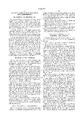
- FIG. 2 is a timing chart for describing the sequence of operation of the interface circuit shown in FIG. 1. The operation of the interface circuit shown in FIG. 1 will be explained below with reference to FIG. 2.
- the frequency of a data timing signal TM is divided into halves by the FF 11 shown in FIG. 1. Namely, a clock signal CK, which is alternately changed to levels "H” and "L” in synchronism with the leading edge of the data timing signal TM, and a clock signal /CK obtained by inverting the clock signal CK are generated by the FF 11 shown in FIG. 1.
- a start signal ST changes to the level "H” in synchronism with the trailing edge of the data timing signal TM, and data of "DT1" is outputted as data DT from the CPU or the like in conjunction with it.
- the start signal ST is supplied to the input terminal D of the FF 21 in the shift register 20, it is held by the FF 21 on the rising edge of the clock signal CK and a latch signal L1 outputted from the FF 21 changes to the level "H". Further, since the latch signal L1 is supplied to the enable terminal G of the latch 41 1 , an odd data signal DTO outputted from the FF 31 is held by the latch 41 1 , so that a signal DD1 outputted from the latch 41 1 results in "DT1".
- the latch signal L1 is supplied to an input terminal D of the latch 22 2 in the shift register 20, it is held by the latch 22 2 in response to the leading edge of the clock signal /CK and a latch signal L2 outputted from the latch 22 2 changes to the level "H". Further, since the latch signal L2 is supplied to the enable terminal G of the latch 41 2 , the even data signal DTE outputted from the FF 32 is held by the latch 41 2 , so that a signal DD2 outputted from the latch 41 2 is brought to "DT2".
- the data DT is changed to "DT3" in synchronism with the trailing edge of the data timing signal TM at time t5.
- the latch signal L1 changes to the level “L” according to the leading edge of the clock signal CK.
- the signal supplied to the enable signal G of the latch 41 1 changes to the level “L” and hence the output signal DD1 of the latch 41 1 is held as "DT1" as it is.
- a latch signal L3 outputted from the latch 22 3 changes to the level “H” according to the rising edge of the clock signal CK. Further, since the latch signal L3 is supplied to the enable terminal G of the latch 41 3 , the odd data signal DTO outputted from the FF 31 is held by the latch 41 3 so that a signal DD3 outputted from the latch 41 3 is brought to "DT3".
- the data DT is changed to "DT4" in synchronism with the trailing edge of the data timing signal TM at time t7.
- the latch signal L3 is taken “H"
- the latch signal L4 outputted from the latch 22 4 changes to the level “H” according to the leading edge of the clock signal /CK. Further, since the latch signal L4 is supplied to the enable terminal G of the latch 41 4 , the even data signal DTE outputted from the FF 32 is held by the latch 41 4 so that a signal DD4 outputted from the latch 41 4 is brought to "DT4".
- the pieces of data DT sequentially supplied from the CPU or the like are successively held in their corresponding latches 41 1 through 41 n in the data latch 40.
- the data of "DT1" through “DTn” are outputted from the latches 41 1 through 41 n as the output signals DD1 through DDn respectively.
- the interface circuit has the FF 11 for dividing the frequency of the data timing signal TM indicative of the timing for the transfer of the data DT into 1/2 to thereby generate the clock signals CK and /CK having the 1/2-divided frequencies respectively, and the shift register 20, FFs 31 and 32 and data latch 40 used for sequentially holding the data DT with rise timing of these clock signals CK and /CK. Therefore, the data can be transferred under the clock signals CK and /CK each having the 1/2-divided frequency employed in the conventional interface circuit. Accordingly, the above-described problems can be solved.
- the shift register 20 comprises the latches 22 2 through 22 n serving as the asynchronous FFs
- the shift register 20 has an advantage in that it can be simplified in circuit scale as compared with the shift register 1 comprised of the conventional synchronous FFs 1 1 through 1 n .
- FIG. 3 is a block diagram of an interface circuit showing a second embodiment of the present invention. Elements of structure common to those illustrated in FIG. 1 are identified by common reference numerals.
- This type of interface circuit is equivalent to an interface circuit supplied with a clock signal CK whose "L" and “H” levels change according to a change in data DT supplied from a CPU or the like, for example.
- the interface circuit is directly supplied with a clock signal CK obtained by 1/2-dividing the frequency of the data timing signal TM shown in FIG. 1 without having to use the data timing signal TM. That is, the clock signal is supplied from the clock source 30. Therefore, the FF 11 shown in FIG. 1 is omitted and an inverter 12 for generating an inverse clock signal /CK obtained by inverting the given clock signal CK is provided.
- Other configurations of the interface circuit are similar to those shown in FIG. 1.
- the interface circuit according to the second embodiment is similar in data transfer operation to the interface circuit according to the first embodiment and has an advantage similar to that obtained by the interface circuit according to the first embodiment. Further, since the frequency of the clock signal CK supplied from the CPU or the like is brought to 1/2, the interface circuit according to the second embodiment has an advantage in that EMI noise from a clock transmission path is reduced.
- FIG. 4 is a block diagram of an interface circuit showing a third embodiment of the present invention. Elements of structure common to those shown in FIG. 1 are identified by common reference numerals.
- This type of interface circuit is equivalent to one capable of separating data DT successively supplied from a CPU or the like into odd data signals DTO, i.e. , "DT1", “DT3”, “DT5", . . . and even data signals DTE, i.e. , "DT2", “DT4", “DT6", . . . in advance, for example and supplying them through different data lines 33 and 34.
- the interface circuit has a delay FF 13 and a selector 14.
- a clock terminal C of the FF 13 and an input terminal A of the selector 14 are supplied with either a data timing signal TM or a clock signal CK.
- An output terminal /Q of the FF 13 is electrically connected to an input terminal D thereof.
- an output terminal Q of the FF 13 is electrically connected to an input terminal B of the selector 14.
- a selection terminal S of the selector 14 is supplied with a select signal SEL. When the select signal SEL is taken "L", the input terminal A of the selector 14 is selected and thereby connected to an output terminal X thereof.
- the select signal SEL is taken "H"
- an input terminal B of the selector 14 is selected and thereby connected to the output terminal X thereof.
- the output of the selector 14 is electrically connected to a holder corresponding to an odd-numbered stage in a shift register 20, i.e., a clock terminal C of an FF 21 and enable terminals G of other holders corresponding to odd-numbered stages therein, i.e., latches 22 3 , 23 5 , . . .
- the output of the selector 14 is electrically connected via an inverter 15 to enable terminals G of holders corresponding to even-numbered stages in the shift register 20, i.e. , latches 22 2 , 22 4 , . . .
- the interface circuit has a data line 33 supplied with data DT or odd data signals DTO, and a data line 34 supplied with even data signals DTE.
- the data line 33 is electrically connected to an input terminal D of a delay FF 35 and an input terminal B of a selector 36.
- the data line 34 is electrically connected to an input terminal A of the selector 36.
- a selection terminal S of the selector 36 is supplied with the select signal SEL.
- the select signal SEL is "L”
- the input terminal A of the selector 36 is selected and thereby connected to an output terminal X of the selector 36.
- the select signal SEL is "H"
- the input terminal B thereof is selected and thereby connected to the output terminal X thereof.
- the output of the selector 36 is electrically connected to an input terminal D of a delay FF 37.
- a clock terminal C of the FF 35 is supplied with the clock signal CK from the output terminal X of the selector 14, and an output terminal Q thereof is electrically commonly connected to input terminals D of odd-numbered latches 41 1 , 41 3 , . . . in a data latch 40.
- the select signal SEL and the clock signal CK outputted from the selector 14 are supplied to a clock terminal C of the FF 37 through an exclusive OR gate (hereinafter called "EOR") 38.
- An output terminal Q of the FF 37 is electrically commonly connected to input terminals D of even-numbered latches 41 2 , 41 4 , . . . in the data latch 40.
- Data DT supplied from the unillustrated CPU or the like is separated into odd-numbered data and even-numbered data. Odd data signals DTO are supplied through the data line 33, whereas even data signals DTE are supplied through the data line 34.
- the input terminal A of the selector 14 is supplied with a clock signal CK.
- the select signal SEL is set to the level "L"
- the input terminals A of the respective selectors 14 and 36 are respectively selected and thereby electrically connected to the output terminals X thereof.
- the clock terminal C of the FF 35 is supplied with the clock signal CK and the odd data signal DTO are held by the FF 35 with the rise timing of the clock signal CK, followed by supply to the data latch 40.
- the clock terminal C of the FF 37 is supplied with the clock signal CK through the EOR 38 and the even data signals DTE are held by the FF 37 with the rise timing of the clock signal CK, followed by supply to the data latch 40.
- the shift register 20 and the data latch 40 are similar in operation to those employed in the first embodiment.
- Data DT is sequentially supplied from the unillustrated CPU or the like via the data line 33.
- a data timing signal TM is supplied to the clock terminal C of the FF 13.
- the select signal SEL is set to the level "H"
- the input terminals B of the respective selectors 14 and 36 are selected and thereby electrically connected to the output terminals X.
- the data DT is commonly supplied to the input terminals D of the FFs 35 and 37.
- the clock terminal C of the FF 35 is supplied with the clock signal CK obtained by 1/2-dividing the frequency of the data timing signal TM with the FF 13.
- the clock terminal C of the FF 37 is supplied with the clock signal /CK inverted by the EOR 38.
- the present interface circuit is identical in circuit configuration to that shown in FIG. 1 and hence the operation similar to that executed by the first embodiment is performed.
- the interface circuit according to the third embodiment has the selectors 14 and 36 as described above, the CPU or the like can separate the data DT into the odd-numbered and even-numbered data and supply them to the interface circuit.
- the interface circuit has another advantage in that a method of reducing the data-transfer rates on the two data lines 33 and 34 and transferring the data DT, using the data line 33 and 34, thereby reducing EMI noise can also be selected, as well as an advantage similar to the first embodiment.
- the data DT is divided into the two: odd data signals DTO and even data signals DTE by the data distribution circuit (FFs 31 and 32), a number of FFs may further be used to divide the data DT into a number of data signals.
- the pulse widths of the latch signals L1, . . . , Ln can be further lengthened and EMI noise can be further reduced.
- the present invention is not limited to the circuit configurations shown in FIGS. 1, 3 and 4. If a circuit having a function similar to that of the above-described circuit is adopted, then any circuit configuration is applicable in the same manner as described above.
- the first embodiment has a frequency dividing means for dividing the frequency of a data timing signal into 1/2 to thereby generate clock signals and first and second holding means for respectively separating sequentially-input data into odd-numbered data and even-numbered data and holding them therein.
- first and second holding means for respectively separating sequentially-input data into odd-numbered data and even-numbered data and holding them therein.
- the second embodiment has first and second temporally store circuits for respectively receiving clock signals each having a cycle twice the cycle of a data timing signal, separating data sequentially inputted according to the clock signals into odd-numbered data and even-numbered data, and holding them therein.
- EMI noise from each clock transmission path can be reduced in addition to the effect obtained in the first embodiment.
- the shift me circuit ans can be simplified in circuit scale as compared with the shift circuit comprised of the synchronous FFs in all.
Abstract
Description
Claims (20)
Applications Claiming Priority (2)
| Application Number | Priority Date | Filing Date | Title |
|---|---|---|---|
| JP9192405A JPH1141299A (en) | 1997-07-17 | 1997-07-17 | Interface circuit |
| JP9-192405 | 1997-07-17 |
Publications (1)
| Publication Number | Publication Date |
|---|---|
| US6040723A true US6040723A (en) | 2000-03-21 |
Family
ID=16290780
Family Applications (1)
| Application Number | Title | Priority Date | Filing Date |
|---|---|---|---|
| US09/114,518 Expired - Fee Related US6040723A (en) | 1997-07-17 | 1998-07-13 | Interface circuit with high speed data transmission |
Country Status (4)
| Country | Link |
|---|---|
| US (1) | US6040723A (en) |
| JP (1) | JPH1141299A (en) |
| KR (1) | KR100333564B1 (en) |
| TW (1) | TW451570B (en) |
Cited By (4)
| Publication number | Priority date | Publication date | Assignee | Title |
|---|---|---|---|---|
| US6239631B1 (en) * | 1998-09-24 | 2001-05-29 | Fujitsu Limited | Integrated circuit device with input buffer capable of correspondence with highspeed clock |
| US6552590B2 (en) * | 2001-02-27 | 2003-04-22 | 3Com Corporation | Clocking scheme for ASIC |
| US6720943B1 (en) * | 1999-04-12 | 2004-04-13 | Lg.Philips Lcd Co., Ltd. | Data interface device |
| US20130050216A1 (en) * | 2011-08-31 | 2013-02-28 | Colin Whitby-Strevens | Methods and apparatus for low power audio visual interface interoperability |
Families Citing this family (1)
| Publication number | Priority date | Publication date | Assignee | Title |
|---|---|---|---|---|
| KR100419149B1 (en) * | 1999-09-22 | 2004-02-14 | 엘지전자 주식회사 | Synchronizing Signal Transfer Control Apparatue And Method For EMI Generating Prevention In Synchronous System |
Citations (2)
| Publication number | Priority date | Publication date | Assignee | Title |
|---|---|---|---|---|
| US5022057A (en) * | 1988-03-11 | 1991-06-04 | Hitachi, Ltd. | Bit synchronization circuit |
| US5886552A (en) * | 1996-12-02 | 1999-03-23 | Electronics And Telecommunications Research Institute | Data retiming circuit |
Family Cites Families (5)
| Publication number | Priority date | Publication date | Assignee | Title |
|---|---|---|---|---|
| JPH0667637A (en) * | 1992-07-21 | 1994-03-11 | Mitsubishi Electric Corp | Synchronous signal discriminating circuit |
| JPH06138838A (en) * | 1992-10-28 | 1994-05-20 | Fuji Electric Co Ltd | Lcd driver integrated circuit element |
| JPH0738535A (en) * | 1993-07-20 | 1995-02-07 | Daido Signal Co Ltd | Noise removing circuit |
| JPH0884069A (en) * | 1994-09-12 | 1996-03-26 | Mitsubishi Electric Corp | Variable frequency divider |
| KR100234717B1 (en) * | 1997-02-03 | 1999-12-15 | 김영환 | Driving voltage supply circuit of lcd panel |
-
1997
- 1997-07-17 JP JP9192405A patent/JPH1141299A/en active Pending
-
1998
- 1998-07-13 US US09/114,518 patent/US6040723A/en not_active Expired - Fee Related
- 1998-07-15 TW TW087111484A patent/TW451570B/en not_active IP Right Cessation
- 1998-07-15 KR KR1019980028602A patent/KR100333564B1/en not_active IP Right Cessation
Patent Citations (2)
| Publication number | Priority date | Publication date | Assignee | Title |
|---|---|---|---|---|
| US5022057A (en) * | 1988-03-11 | 1991-06-04 | Hitachi, Ltd. | Bit synchronization circuit |
| US5886552A (en) * | 1996-12-02 | 1999-03-23 | Electronics And Telecommunications Research Institute | Data retiming circuit |
Cited By (5)
| Publication number | Priority date | Publication date | Assignee | Title |
|---|---|---|---|---|
| US6239631B1 (en) * | 1998-09-24 | 2001-05-29 | Fujitsu Limited | Integrated circuit device with input buffer capable of correspondence with highspeed clock |
| US6720943B1 (en) * | 1999-04-12 | 2004-04-13 | Lg.Philips Lcd Co., Ltd. | Data interface device |
| US6552590B2 (en) * | 2001-02-27 | 2003-04-22 | 3Com Corporation | Clocking scheme for ASIC |
| US20130050216A1 (en) * | 2011-08-31 | 2013-02-28 | Colin Whitby-Strevens | Methods and apparatus for low power audio visual interface interoperability |
| US8831161B2 (en) * | 2011-08-31 | 2014-09-09 | Apple Inc. | Methods and apparatus for low power audio visual interface interoperability |
Also Published As
| Publication number | Publication date |
|---|---|
| TW451570B (en) | 2001-08-21 |
| JPH1141299A (en) | 1999-02-12 |
| KR100333564B1 (en) | 2002-06-20 |
| KR19990013886A (en) | 1999-02-25 |
Similar Documents
| Publication | Publication Date | Title |
|---|---|---|
| KR101089153B1 (en) | Method for data signal transfer across different clock-domains | |
| US4853653A (en) | Multiple input clock selector | |
| US5973507A (en) | Exclusive-or gate for use in delay using transmission gate circuitry | |
| US8301932B2 (en) | Synchronising between clock domains | |
| US5600824A (en) | Clock generating means for generating bus clock and chip clock synchronously having frequency ratio of N-1/N responsive to synchronization signal for inhibiting data transfer | |
| US6275546B1 (en) | Glitchless clock switch circuit | |
| US7409005B2 (en) | High speed data transmitter and transmitting method thereof | |
| EP2156440B1 (en) | Integrated circuit for clock generation for memory devices | |
| KR20050041612A (en) | Memory device for enhancing operation margin about data output control | |
| US5511181A (en) | Polycyclic timing system and apparatus for pipelined computer operation | |
| US6049236A (en) | Divide-by-one or divide-by-two qualified clock driver with glitch-free transitions between operating frequencies | |
| US6507230B1 (en) | Clock generator having a deskewer | |
| US6040723A (en) | Interface circuit with high speed data transmission | |
| JP3846871B2 (en) | Parallel / serial conversion circuit, serial data generation circuit, synchronization signal generation circuit, clock signal generation circuit, serial data transmission device, serial data reception device, and serial data transmission system | |
| JP2002182777A (en) | Clock switching circuit | |
| US6026141A (en) | One load conditional look ahead counter | |
| US6388484B1 (en) | Clock control circuit | |
| US7123674B2 (en) | Reducing latency and power in asynchronous data transfers | |
| US6441666B1 (en) | System and method for generating clock signals | |
| US20060198479A1 (en) | Data synchronizer system | |
| JP2001203585A (en) | Parallel-serial conversion circuit | |
| KR100429867B1 (en) | Output buffer for double data rate semiconductor device | |
| JPH05130094A (en) | Clock transfer circuit | |
| JPS62202624A (en) | High speed data reception circuit system | |
| KR100278271B1 (en) | A clock frequency divider |
Legal Events
| Date | Code | Title | Description |
|---|---|---|---|
| AS | Assignment |
Owner name: OKI ELECTRIC INDUSTRY CO., LTD., JAPAN Free format text: ASSIGNMENT OF ASSIGNORS INTEREST;ASSIGNOR:SATO, HISATAKE;REEL/FRAME:009331/0505 Effective date: 19980709 |
|
| FEPP | Fee payment procedure |
Free format text: PAYOR NUMBER ASSIGNED (ORIGINAL EVENT CODE: ASPN); ENTITY STATUS OF PATENT OWNER: LARGE ENTITY |
|
| FPAY | Fee payment |
Year of fee payment: 4 |
|
| FPAY | Fee payment |
Year of fee payment: 8 |
|
| AS | Assignment |
Owner name: OKI SEMICONDUCTOR CO., LTD., JAPAN Free format text: CHANGE OF NAME;ASSIGNOR:OKI ELECTRIC INDUSTRY CO., LTD.;REEL/FRAME:022299/0368 Effective date: 20081001 Owner name: OKI SEMICONDUCTOR CO., LTD.,JAPAN Free format text: CHANGE OF NAME;ASSIGNOR:OKI ELECTRIC INDUSTRY CO., LTD.;REEL/FRAME:022299/0368 Effective date: 20081001 |
|
| REMI | Maintenance fee reminder mailed | ||
| LAPS | Lapse for failure to pay maintenance fees | ||
| LAPS | Lapse for failure to pay maintenance fees |
Free format text: PATENT EXPIRED FOR FAILURE TO PAY MAINTENANCE FEES (ORIGINAL EVENT CODE: EXP.); ENTITY STATUS OF PATENT OWNER: LARGE ENTITY |
|
| STCH | Information on status: patent discontinuation |
Free format text: PATENT EXPIRED DUE TO NONPAYMENT OF MAINTENANCE FEES UNDER 37 CFR 1.362 |
|
| FP | Lapsed due to failure to pay maintenance fee |
Effective date: 20120321 |