US6050290A - Hose reel apparatus - Google Patents
Hose reel apparatus Download PDFInfo
- Publication number
- US6050290A US6050290A US09/105,069 US10506998A US6050290A US 6050290 A US6050290 A US 6050290A US 10506998 A US10506998 A US 10506998A US 6050290 A US6050290 A US 6050290A
- Authority
- US
- United States
- Prior art keywords
- drum
- driving shaft
- flexible member
- reel apparatus
- frame assembly
- Prior art date
- Legal status (The legal status is an assumption and is not a legal conclusion. Google has not performed a legal analysis and makes no representation as to the accuracy of the status listed.)
- Expired - Fee Related
Links
Images


Classifications
-
- B—PERFORMING OPERATIONS; TRANSPORTING
- B65—CONVEYING; PACKING; STORING; HANDLING THIN OR FILAMENTARY MATERIAL
- B65H—HANDLING THIN OR FILAMENTARY MATERIAL, e.g. SHEETS, WEBS, CABLES
- B65H75/00—Storing webs, tapes, or filamentary material, e.g. on reels
- B65H75/02—Cores, formers, supports, or holders for coiled, wound, or folded material, e.g. reels, spindles, bobbins, cop tubes, cans, mandrels or chucks
- B65H75/34—Cores, formers, supports, or holders for coiled, wound, or folded material, e.g. reels, spindles, bobbins, cop tubes, cans, mandrels or chucks specially adapted or mounted for storing and repeatedly paying-out and re-storing lengths of material provided for particular purposes, e.g. anchored hoses, power cables
- B65H75/38—Cores, formers, supports, or holders for coiled, wound, or folded material, e.g. reels, spindles, bobbins, cop tubes, cans, mandrels or chucks specially adapted or mounted for storing and repeatedly paying-out and re-storing lengths of material provided for particular purposes, e.g. anchored hoses, power cables involving the use of a core or former internal to, and supporting, a stored package of material
- B65H75/44—Constructional details
- B65H75/4402—Guiding arrangements to control paying-out and re-storing of the material
- B65H75/4405—Traversing devices; means for orderly arranging the material on the drum
- B65H75/4407—Traversing devices; means for orderly arranging the material on the drum positively driven, e.g. by a transmission between the drum and the traversing device
-
- B—PERFORMING OPERATIONS; TRANSPORTING
- B65—CONVEYING; PACKING; STORING; HANDLING THIN OR FILAMENTARY MATERIAL
- B65H—HANDLING THIN OR FILAMENTARY MATERIAL, e.g. SHEETS, WEBS, CABLES
- B65H75/00—Storing webs, tapes, or filamentary material, e.g. on reels
- B65H75/02—Cores, formers, supports, or holders for coiled, wound, or folded material, e.g. reels, spindles, bobbins, cop tubes, cans, mandrels or chucks
- B65H75/34—Cores, formers, supports, or holders for coiled, wound, or folded material, e.g. reels, spindles, bobbins, cop tubes, cans, mandrels or chucks specially adapted or mounted for storing and repeatedly paying-out and re-storing lengths of material provided for particular purposes, e.g. anchored hoses, power cables
- B65H75/38—Cores, formers, supports, or holders for coiled, wound, or folded material, e.g. reels, spindles, bobbins, cop tubes, cans, mandrels or chucks specially adapted or mounted for storing and repeatedly paying-out and re-storing lengths of material provided for particular purposes, e.g. anchored hoses, power cables involving the use of a core or former internal to, and supporting, a stored package of material
- B65H75/40—Cores, formers, supports, or holders for coiled, wound, or folded material, e.g. reels, spindles, bobbins, cop tubes, cans, mandrels or chucks specially adapted or mounted for storing and repeatedly paying-out and re-storing lengths of material provided for particular purposes, e.g. anchored hoses, power cables involving the use of a core or former internal to, and supporting, a stored package of material mobile or transportable
- B65H75/403—Carriage with wheels
-
- B—PERFORMING OPERATIONS; TRANSPORTING
- B65—CONVEYING; PACKING; STORING; HANDLING THIN OR FILAMENTARY MATERIAL
- B65H—HANDLING THIN OR FILAMENTARY MATERIAL, e.g. SHEETS, WEBS, CABLES
- B65H75/00—Storing webs, tapes, or filamentary material, e.g. on reels
- B65H75/02—Cores, formers, supports, or holders for coiled, wound, or folded material, e.g. reels, spindles, bobbins, cop tubes, cans, mandrels or chucks
- B65H75/34—Cores, formers, supports, or holders for coiled, wound, or folded material, e.g. reels, spindles, bobbins, cop tubes, cans, mandrels or chucks specially adapted or mounted for storing and repeatedly paying-out and re-storing lengths of material provided for particular purposes, e.g. anchored hoses, power cables
- B65H75/38—Cores, formers, supports, or holders for coiled, wound, or folded material, e.g. reels, spindles, bobbins, cop tubes, cans, mandrels or chucks specially adapted or mounted for storing and repeatedly paying-out and re-storing lengths of material provided for particular purposes, e.g. anchored hoses, power cables involving the use of a core or former internal to, and supporting, a stored package of material
- B65H75/44—Constructional details
- B65H75/4436—Arrangements for yieldably braking the reel or the material for moderating speed of winding or unwinding
- B65H75/4442—Arrangements for yieldably braking the reel or the material for moderating speed of winding or unwinding acting on the reel
-
- B—PERFORMING OPERATIONS; TRANSPORTING
- B65—CONVEYING; PACKING; STORING; HANDLING THIN OR FILAMENTARY MATERIAL
- B65H—HANDLING THIN OR FILAMENTARY MATERIAL, e.g. SHEETS, WEBS, CABLES
- B65H75/00—Storing webs, tapes, or filamentary material, e.g. on reels
- B65H75/02—Cores, formers, supports, or holders for coiled, wound, or folded material, e.g. reels, spindles, bobbins, cop tubes, cans, mandrels or chucks
- B65H75/34—Cores, formers, supports, or holders for coiled, wound, or folded material, e.g. reels, spindles, bobbins, cop tubes, cans, mandrels or chucks specially adapted or mounted for storing and repeatedly paying-out and re-storing lengths of material provided for particular purposes, e.g. anchored hoses, power cables
- B65H75/38—Cores, formers, supports, or holders for coiled, wound, or folded material, e.g. reels, spindles, bobbins, cop tubes, cans, mandrels or chucks specially adapted or mounted for storing and repeatedly paying-out and re-storing lengths of material provided for particular purposes, e.g. anchored hoses, power cables involving the use of a core or former internal to, and supporting, a stored package of material
- B65H75/44—Constructional details
- B65H75/4457—Arrangements of the frame or housing
- B65H75/4471—Housing enclosing the reel
-
- B—PERFORMING OPERATIONS; TRANSPORTING
- B65—CONVEYING; PACKING; STORING; HANDLING THIN OR FILAMENTARY MATERIAL
- B65H—HANDLING THIN OR FILAMENTARY MATERIAL, e.g. SHEETS, WEBS, CABLES
- B65H2701/00—Handled material; Storage means
- B65H2701/30—Handled filamentary material
- B65H2701/33—Hollow or hose-like material
-
- Y—GENERAL TAGGING OF NEW TECHNOLOGICAL DEVELOPMENTS; GENERAL TAGGING OF CROSS-SECTIONAL TECHNOLOGIES SPANNING OVER SEVERAL SECTIONS OF THE IPC; TECHNICAL SUBJECTS COVERED BY FORMER USPC CROSS-REFERENCE ART COLLECTIONS [XRACs] AND DIGESTS
- Y10—TECHNICAL SUBJECTS COVERED BY FORMER USPC
- Y10T—TECHNICAL SUBJECTS COVERED BY FORMER US CLASSIFICATION
- Y10T137/00—Fluid handling
- Y10T137/6851—With casing, support, protector or static constructional installations
- Y10T137/6918—With hose storage or retrieval means
- Y10T137/6932—With retrieval means
Definitions
- the present invention relates to a reel apparatus. More particularly, the invention pertains to an enclosed reel apparatus including a drum for supporting a flexible member, such as a line, cable or hose, and a mechanism for winding the flexible member on the drum.
- a flexible member such as a line, cable or hose
- a very common assembly includes a horizontally aligned, coaxial drum and crank shaft.
- the horizontal alignment of the crank shaft requires an operator to bend up and down to rotate the handle. Accordingly, this type of assembly can be cumbersome to operate and may subject the operator to back spasms and fatigue.
- hose reel assemblies Another complication associated only with hose reel assemblies is the lack of access to water except through the hose. Indeed, residential dwellings often times only have a single spigot in the front and rear of the dwelling to hook up the hose to a water supply. In this case, the operator usually is unable to undertake other projects requiring use of water once the hose reel is connected to the spigot.
- a reel apparatus for winding and paying out flexible line material comprises a housing; a drum, on which the line material is wound, mounted within the housing, the drum adapted to be oriented along either a vertical or a horizontal axis, a driving shaft for rotating the drum; a torque transmission mechanism coupling the driving shaft to the drum; and crank handle mounted on an upper portion of the housing, the crank handle being operatively connected to the driving shaft for rotating the driving shaft and the drum to wind line on and off the drum.
- crank handle and driving shaft are mounted to rotate about a vertical axis, regardless of the orientation of the drum.
- the drum is disposed vertically, it is desirable to provide various mechanisms which prevent the flexible line from coming out of alignment upon the drum.
- the flexible line material is a hollow tube or hose for passing fluid from one end to the other.
- the reel apparatus preferably includes an auxiliary spigot on the reel housing to provide fluid access without unplugging the apparatus from the main spigot.
- FIG. 1 is a side perspective view of an embodiment of the hose reel apparatus of the present invention.
- FIG. 2 is a partial sectional view of the hose reel apparatus of FIG. 1.
- FIG. 3 is a front, elevational view of a portion of the rotation mechanism of FIG. 1.
- FIG. 4 is a top plan view of the crank handle of FIG. 2.
- FIG. 5 is a view of a presently preferred drag-mechanism of the present invention.
- FIG. 6 is a view of a presently preferred drag-mechanism of the present invention.
- FIG. 7 is an exploded view of the hose reel apparatus of FIG. 1.
- FIG. 8 is an exploded view of the coil-guide roller of FIG. 7.
- FIG. 9 is a view of the coil-guide roller of FIG. 7.
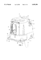
- FIG. 10 is a bottom view of the hose reel apparatus of the present invention.
- FIG. 11 is an enlarged view of the piping of FIG. 2.
- FIG. 12 is a sectional view of the driving shaft and guide member of FIG. 3.
- FIG. 13 is an exploded view of a presently preferred pawl mechanism.
- FIG. 14 is a side view of the pawl mechanism of FIG. 13.
- FIG. 15 is a top sectional view take n along line A--A in FIG. 14.
- FIG. 16 is a perspective view of the front of another embodiment of the invention.
- FIG. 17 is a perspective view of the rear of the embodiment of the invention shown in FIG. 16.
- FIG. 18 is another perspective view of the front of the embodiment of the invention shown in FIG. 16.
- FIG. 19 is a partial sectional view of the hose reel apparatus of FIG. 1.
- flexible member or line are used in their broadest sense to include, among other things, flexible hose for liquid or gas, electrical cable, and a flexible length of wire, rope, plastic, fiberglass, or plastic encapsulated conductive material.
- the reel apparatus which is identified by reference numeral 10, includes an housing or enclosure 12 and a base 14.
- the base 14 is weighted to prevent tipping of the entire apparatus.
- foot pads 16 or the like may be added to increase stability and allow an operator to stand with his feet on the pads.
- the foot pads may further include holes 18 so that one or more spikes (shown in dashed lines) may be driven into the ground through the holes 18 to anchor the apparatus at a desired location.
- the base 14 also includes wheels 20 to enable an operator to transport the apparatus with ease.
- a molded fender (not shown) may be used for protection and to hide the wheels 20 from view.
- the enclosure 12 for the line reel apparatus provides, among other things, protection from the elements.
- the enclosure 12 joins the top of the base 14 and surrounds the mechanism of the apparatus.
- An output line 22 may be reeled in and out of the line reel apparatus 10 through an elongated opening 24 in the enclosure 12.
- the line reel apparatus may be formed from any material
- the enclosure 12 preferably is integrally formed from a resinous material to add stiffness to the entire apparatus.
- the enclosure 12 includes a telescoping handle 26 above the wheels 20.
- the telescoping handle 26, shown in FIG. 1, is in a retracted or stowed position. When an operator wishes to move the apparatus, the operator raises the telescoping handle 26 for greater ease of use.
- the apparatus includes a drum 28 for supporting the output line 22.
- the enclosure 12 and the base 14 support the drum 28 such that the axis of the drum 28 is oriented vertically.
- Bearings 30 or the like may rotatably support the drum 28 on the base 14.
- a bushing 32 rotatably couples the drum 28 to the enclosure 12.
- the drum 28 has ribs 29 to hold a first layer of line wound onto the drum 28 in alignment.
- the line reel apparatus includes a rotation mechanism.
- the rotation mechanism for the line reel apparatus 10 includes a crank handle 34, a driving shaft 36, and a torque transmission device coupling the drum 28 and the driving shaft 36.
- the driving shaft 36 is supported by the enclosure 12 and the base 14 in parallel with the axis of the drum 28.
- a pivot joint 38 may be provided to join the crank handle 34 to the top of the driving shaft 36.
- the crank handle 34 allows an operator of the line reel apparatus to reel the output line 22 onto the drum 28.
- the preferred vertical orientation of the driving shaft 36 enables the operator to rotate the crank handle 34 without bending up and down, thus reducing fatigue.
- the pivot joint 38 between the crank handle 34 and the top of the driving shaft 36 allows the operator to engage or disengage the crank handle 34 with the top of the driving shaft 36.
- the crank handle 34 When the crank handle 34 is in the disengaged position, it may be stowed to one side of the top of the enclosure 12, as shown in FIG. 1.
- the crank handle 34 allows the operator of the apparatus to rotate the driving shaft 36 in a first direction.
- the reel apparatus includes elements for maintaining the line in a substantially taught coiled form, such that the line is distributed evenly along the drum, is not bunched up, or susceptible to slippage along the length of the drum.
- the means for maintaining the line in substantially taught alignment includes a ratcheting mechanism preferably between the crank handle 34 and the driving shaft 36.
- the driving shaft includes a ratcheting gear 40 at its top.
- An internal slot 44 in the crank handle 34 opens into the aperture 42.
- the slot 44 slidably receives a spring-biased pawl 46.
- An external slot 48 extends from the internal slot 44 to the outside of the crank handle 34.
- a member 50 fixed to the pawl 46 slides along the external slot 48.
- the ends of the external slot 48 define stops for the member 50 and limit movement of the pawl 46 within the internal slot 44 to a distance approximately defined by the ratcheting gear tooth depth.
- a spring biased pawl in a second embodiment of the ratcheting mechanism, as generally illustrated in FIGS. 13-15, includes a stud pawl 136 rotatably carried in an end of the driving shaft 36.
- the inside surface of the driving shaft 36 has notches 138.
- the stud pawl 136 further includes outwardly biased cut out portions 140 for engaging the notches 138.
- the stud pawl 136 includes a stud 142 for engaging the crank handle 34 in the engaged position.
- the ratcheting mechanism prevents use of the handle 34 for rotating the driving shaft 36 in a second direction, opposite from the first direction. It may be desirable to prevent rotation in the second direction using the crank handle 34 to prevent the output line 22 from becoming loose upon the drum 28. Other mechanisms, discussed below, further prevent the output line 22 from loosening on the drum 28. If the output line 22 becomes loose upon the drum 28, it can slide down and out of alignment on the drum 28 making it more difficult to subsequently reel the output line 22 in or out of the apparatus.
- the torque transmission means may include sprockets 52 and 54 fixed to the bottom ends of the driving shaft 36 and the drum 28, and a chain drive 56 engaging the two sprockets 52 and 54.
- the sprocket 52 may be joined to the inside of the driving shaft by a spline connection (not shown).
- Rotation of the driving shaft 36 or the drum 28 causes the other of the driving shaft or the drum to rotate.
- both the driving shaft 36 and the drum 28 rotate in the first direction. Rotational energy is transferred between the driving shaft 36 and the drum 28 by the chain drive 56.
- the output line is reeled into the apparatus by rotation of the drum.
- the driving shaft 36 further includes a reversing screw 58 along the length of the driving shaft corresponding approximately to an axial length of the drum 28.
- the reversing screw 58 includes two grooves 60 and 62 connected at both ends of the reversing screw and crisscrossing along the length of the reversing screw. One of the two grooves is a right-hand groove and the other is a left-hand groove.
- a follower 63 in a guide member 64 engages at least one of the grooves 60 or 62 of the reversing screw 58.
- a spring 132 biases the follower 63 towards the driving shaft and into one of the grooves 60 or 62.
- the follower 63 can be disengaged from the grooves by pulling on pull ring 134 so that the position of the guide member can be adjusted.
- the output line 22 feeds through an opening 66 in the guide member.
- a support column 68 constrains the guide member 64 to translational motion along the axis of the reversing screw 58.
- the guide member 64 causes the output line 22 to wind neatly around the drum 28. Rotation of the reversing screw 58 in either the first or second direction causes the guide member 64 to travel up and down the reversing screw. When the guide member 64 reaches either end of the reversing screw 58, it reverses the direction it travels along the screw. When the crank handle 34 is rotated in the first direction, the driving shaft 36 and the drum 28 also rotate in the first direction. The guide member 64 neatly feeds the output line 22 onto the drum 28 such that the output line does not bunch up. When the output line 22 is pulled out of the line reel apparatus 10, the drum 28 and the driving shaft 36 rotate in the second direction. The guide member 64 once again moves up and down the driving shaft 36 to maintain the output line 22 in alignment on the drum 28, and hence is another element which contributes to maintaining the line in a substantially taught coiled form along the drum 28.
- tension in the line is also provided by a drag mechanism.
- the drag mechanism comprises five pins 72, 74, 76, 78, and 80 projecting from the base 14, a brake block 82 resting on the base 14 adjacent a lower flange 84 of the drum 28, and a spring 86.
- One of the pins 72 is received in a slot 88 of the brake block to constrain the translational movement of the brake block 82.
- Second and third pins 74 and 76 constrain rotational movement of the brake block 82.
- Fourth and fifth pins 78 and 80 support the spring 86 to press the brake block 82 into contact with the lower flange of the drum.
- the drag mechanism allows for free movement of the drum when the output line 22 is pulled into the line reel apparatus 10 and wound onto the drum 28, as shown in FIG. 5. However, as shown in FIG. 6, when the operator pulls the output line 22 out of the apparatus, the drag mechanism presses against the lower flange of the drum 28. This increases the tension in the output line 22 such that the output line does not loosen and slide down upon the drum 28.
- the present invention may further include a coil guide arm 90 and a coil guide roller 92.
- the coil guide roller 92 includes combs 94 to maintain the alignment of the output line 22 on the drum 28.
- Upper and lower roller pivots 96 and 98 sit in bushings 100 and 102 and allow the coil guide roller 92 to rotate with respect to the coil guide arm 90.
- the coil guard arm 90 includes upper and lower arm pivots 104 and 106, fitting into pivot holes in the enclosure 12 and the base 14, respectively.
- a rotational axis, extending between the upper and lower arm pivots 104 and 106 of the coil guard arm 90, is spaced in parallel relative to the drum axis. As shown in FIG.
- a torsion spring 108 fits around the lower arm pivot 106 and includes an upper inwardly bent member 110 and a lower outwardly oriented member 112.
- the inwardly bent member 110 sits in a slot 114.
- the outwardly oriented member is fixed to the bottom of the base 14, as illustrated in FIG. 10.
- the torsion spring 108 biases the coil guide arm 90 inwards towards the drum 28.
- the coil guide arm 90 and the coil guide roller 92 further prevent the output line 22 from sliding down on the drum 28.
- the reel apparatus is provided with a drum line 23 having a connector end 25 at one of its ends for joining the output line 22 with the drum line 23.
- the drum hose line is long enough to extend from the base of the drum 28 to just beyond the guide member 64 at its lowest position, as illustrated in FIG. 19, so that when a customer attaches his own output line 22 to the connector end 25, he does not have to reach into or dismantle the reel apparatus 10 to connect the output line 22 to the base.
- the present invention includes pipe connections.
- a leader hose 116 connects the line reel apparatus with an outside spigot (not shown), i.e., water source, to provide water to the apparatus.
- the leader hose 116 connects with a first branch of a T-shaped connector 118.
- the pipe connector 118 directs incoming water in two directions through second and third branches. Some of the water entering the pipe connector 118 exits through its second branch to a rotatable, auxiliary spigot 120 (See FIG. 1).
- the rotatable, auxiliary spigot 120 includes a manually operated valve 122.
- the pipe connector 118 directs the rest of the water through its third branch up through the bottom of the drum 28 to the hose 22.
- a connection pipe 124 extends between the third branch of the pipe connector and a water pipe 126 at the bottom of the drum 28.
- the water pipe 126 rotatably joins with a feed pipe 128.
- the feed pipe 128 is fixed to and supported by the drum 28 so that it rotates with the drum 28.
- the output line 22 is attachable to the open end of the feed pipe 128.
- the reel apparatus is provided with a drum hose, as illustrated in FIG. 19, the output hose 22 is attachable to the connector end 25 of the drum hose 23.
- the opposite end of the feed pipe 128 makes a female connection with the water pipe 126. Because bearings 30 carry all of the load of the drum 28 on the base 14, there is no loading between the feed and the water pipe.
- ring-shaped seals 130 having U-shaped cross-sections prevent water from leaking at the joint.
- other types of seals may be used, such as O-ring seals.
- the drum 28' has a horizontally oriented axis.
- the driving shaft 36' transmits torque to the drum through a drive mechanism 132. Torque is also transmitted to the reversing screw 58' through torque transmission means.
- the torque transmission means may be a sprocket and chain assembly.
- the reversing screw 58' and the guide member 64' operate in much the same manner as the vertically oriented drum.
- the reel apparatus of the present invention is operated by withdrawing the line 22 by pulling it from the line reel apparatus.
- the operator may reel the line 22 back into the assembly using the crank handle 34 to rotate the drum 28. Because the crank handle 34 rotates about a vertical axis and is disposed generally above the drum, the operator does not need to bend up and down to crank the line into the apparatus and is thus less likely to experience back spasms and fatigue.
- Various mechanisms such as ribs on the drum, a ratcheting mechanism, a drag mechanism, and/or a coil guide, may be utilized to prevent the line 22 from coming out of alignment on the drum 28. Because the line 22 is kept in alignment, it winds on and off of the drum 28 smoothly.
- the ratcheting mechanism may be provided between the crank handle 34 and the driving shaft 36 to prevent use of the handle 34 for rotating the drum 28 in a direction opposite from the winding on direction. If the drum 28 were rotated in this second, opposite direction, the rotation of the drum 28 would push the line 22 off of the drum 28. The line 22 would then become loose upon the drum 28.
- the drag mechanism allows for free movement of the drum 28 when the output line 22 is pulled into the line reel apparatus and wound onto the drum 28.
- the drag mechanism presses against the lower flange of the drum 28, thus increasing the tension in the output line 22.
- the coil guide arm 90 and roller 92 are biased against the drum 28 and push the line 22 onto the drum.
- the drum 28 may also be ribbed to hold the first layer of line wound onto the drum 28 in alignment.
- the apparatus may be provided with various piping mechanisms and the leader hose 116 to supply water or some other fluid which an operator wishes to distribute.
- the leader hose 116 is attached to a supply spigot. It is preferable to provide the apparatus with an auxiliary spigot 120 to provide access to the water or fluid without disconnecting the leader hose 116 from the supply spigot. This enables an operator to access the water or fluid from either a remote end of the output hose or the auxiliary spigot 120.
- pulleys may be fixed to the bottom of the driving shaft and the drum.
- a drive belt, engaging the pulleys may also be utilized to transfer rotational energy between the driving shaft 36 and the drum 28.
Abstract
Description
Claims (10)
Priority Applications (3)
| Application Number | Priority Date | Filing Date | Title |
|---|---|---|---|
| US09/105,069 US6050290A (en) | 1997-08-01 | 1998-06-26 | Hose reel apparatus |
| PCT/US1998/015887 WO1999006316A1 (en) | 1997-08-01 | 1998-07-30 | Hose reel apparatus |
| AU86755/98A AU8675598A (en) | 1997-08-01 | 1998-07-30 | Hose reel apparatus |
Applications Claiming Priority (2)
| Application Number | Priority Date | Filing Date | Title |
|---|---|---|---|
| US5456097P | 1997-08-01 | 1997-08-01 | |
| US09/105,069 US6050290A (en) | 1997-08-01 | 1998-06-26 | Hose reel apparatus |
Publications (1)
| Publication Number | Publication Date |
|---|---|
| US6050290A true US6050290A (en) | 2000-04-18 |
Family
ID=26733181
Family Applications (1)
| Application Number | Title | Priority Date | Filing Date |
|---|---|---|---|
| US09/105,069 Expired - Fee Related US6050290A (en) | 1997-08-01 | 1998-06-26 | Hose reel apparatus |
Country Status (3)
| Country | Link |
|---|---|
| US (1) | US6050290A (en) |
| AU (1) | AU8675598A (en) |
| WO (1) | WO1999006316A1 (en) |
Cited By (27)
| Publication number | Priority date | Publication date | Assignee | Title |
|---|---|---|---|---|
| US6279848B1 (en) * | 2000-04-14 | 2001-08-28 | Great Stuff, Inc. | Reel having an improved reciprocating mechanism |
| US6338360B2 (en) * | 2000-05-10 | 2002-01-15 | Ames True Temper Inc. | Hose reel carrier assembly |
| FR2827587A1 (en) * | 2001-07-18 | 2003-01-24 | Sotep | Hose reel is mounted so that its axis of rotation is vertical, hose passing through aperture in cylindrical sleeve, on which a ring of brushes or sponge is mounted to clean it |
| US6550266B1 (en) * | 2002-02-08 | 2003-04-22 | Dennis G. Miller | Modular icemaker connecting device |
| US6742740B2 (en) * | 2001-08-20 | 2004-06-01 | Suncast Corporation | Hose cart with ease of use features |
| US20040188558A1 (en) * | 2003-03-28 | 2004-09-30 | Brian Moon | Hose reel cart with elevated crank handle |
| US20050017117A1 (en) * | 2003-01-17 | 2005-01-27 | Brian Moon | Direct current powered hose rewinding apparatus |
| US6913221B2 (en) | 2002-01-18 | 2005-07-05 | Suncast Corporation | Powered hose reel safety enclosure |
| US20060006270A1 (en) * | 2002-11-22 | 2006-01-12 | Hiroyuki Tanji | Hose reel |
| WO2006010899A2 (en) * | 2004-07-28 | 2006-02-02 | Hozelock Limited | Hose reels |
| US20060054731A1 (en) * | 2004-09-16 | 2006-03-16 | Hydro-Industries Tynat Ltd. | System for evenly winding a hose on a reel |
| WO2006075137A2 (en) * | 2005-01-12 | 2006-07-20 | Hozelock Limited | Cased hose reels |
| US20070045502A1 (en) * | 2005-09-01 | 2007-03-01 | Suncast Inc. | Rotary table for enclosed hose reel |
| US20070114319A1 (en) * | 2005-11-23 | 2007-05-24 | Torrence Anderson | Low entry hose reel device with elevated point of operation |
| US20070144584A1 (en) * | 2005-12-14 | 2007-06-28 | Stephen Hatcher | Swiveling hose reel |
| US20090127368A1 (en) * | 2007-11-16 | 2009-05-21 | Kristen Omli | Pool Lane Line Reel Apparatuses, Systems, And Methods |
| US20100155520A1 (en) * | 2008-12-22 | 2010-06-24 | Suncast Technologies Llc | Hose Reel Cart With Multi-Position Crank Handle |
| US20100294459A1 (en) * | 2009-05-21 | 2010-11-25 | Ron Williams | Heat exchange configuration for use in a mobile system cleaning apparatus |
| US20110030812A1 (en) * | 2009-08-04 | 2011-02-10 | Mckimmy Matthew | Gearless Hose Tracking Assembly For Hose Reel Applications |
| CN104047325A (en) * | 2013-03-13 | 2014-09-17 | 哈尼施费格尔技术公司 | Reel With Stepped Configuration |
| US8851413B2 (en) | 2012-11-02 | 2014-10-07 | Suncast Technologies, Llc | Reel assembly |
| US20160122155A1 (en) * | 2013-06-12 | 2016-05-05 | Graco Minnesota Inc. | Modular direct drive system for powered hose reels |
| US20170022026A1 (en) * | 2015-07-24 | 2017-01-26 | Karcher North America, Inc. | Reel system with supplemental features |
| US20180334353A1 (en) * | 2017-05-17 | 2018-11-22 | Fiskars Finland Oy Ab | Hose reel |
| US10858217B2 (en) | 2017-05-17 | 2020-12-08 | Fiskars Finland Oy Ab | Hose reel |
| CN115414129A (en) * | 2022-11-04 | 2022-12-02 | 北京云力境安科技有限公司 | Flexible surgical instrument, flexible instrument and instrument conveying unit thereof |
| US20230322531A1 (en) * | 2019-02-28 | 2023-10-12 | T-Max (Hangzhou) Technology Co., Ltd. | Winch, rope guide and transmission device having clutch function |
Citations (24)
| Publication number | Priority date | Publication date | Assignee | Title |
|---|---|---|---|---|
| US32510A (en) * | 1861-06-11 | Improved telegraphic apparatus | ||
| US1850677A (en) * | 1930-11-28 | 1932-03-22 | Harry F Kieneman | Hose reel |
| US1850676A (en) * | 1930-09-29 | 1932-03-22 | Harry F Kieneman | Hose reel |
| US1875467A (en) * | 1932-09-06 | Level winding mechanism tor sewer cleaners | ||
| FR798418A (en) * | 1935-11-29 | 1936-05-16 | Garden hose reel combined with a garden hose | |
| US2301208A (en) * | 1941-05-12 | 1942-11-10 | Richard J Gear | Hose reel apparatus |
| US2595655A (en) * | 1950-04-14 | 1952-05-06 | Clifford B Hannay & Son Inc | Hose reel |
| FR2030996A5 (en) * | 1969-10-08 | 1970-11-13 | Apa Kg Bauder Otto | |
| CH534632A (en) * | 1972-02-16 | 1973-03-15 | Streit Fritz | Hose reel with braking device |
| AU4170378A (en) * | 1977-11-24 | 1979-05-31 | Harrison J H | Hose reel |
| US4334670A (en) * | 1979-01-17 | 1982-06-15 | Taiyo Sengu Co., Ltd. | Anchor winch equipment |
| US4512361A (en) * | 1982-11-29 | 1985-04-23 | Suncast Corporation | Hose storage apparatus |
| US4513772A (en) * | 1983-07-25 | 1985-04-30 | Richard Fisher | Automatic hose reel |
| US4534384A (en) * | 1982-12-15 | 1985-08-13 | Flight Refueling, Inc. | Reel system for axially extending hose |
| JPS6155068A (en) * | 1984-08-27 | 1986-03-19 | Mitsuo Ishida | Device for taking up hose in forming a line |
| JPS61203079A (en) * | 1985-03-01 | 1986-09-08 | Mitsuo Ishida | Regularly winding hose reel |
| US4777976A (en) * | 1987-06-24 | 1988-10-18 | Suncast Corporation | Portable hose cart and method of use |
| US4974627A (en) * | 1989-08-11 | 1990-12-04 | The Specialty Mfg. Co. | Garden hose reel caddy |
| DE9401104U1 (en) * | 1994-01-24 | 1994-03-10 | Shing Kao Chen | Hose trolley |
| WO1994027904A1 (en) * | 1993-05-20 | 1994-12-08 | Reel-A-Pail, Inc. | Reel inside bucket |
| US5381820A (en) * | 1994-04-04 | 1995-01-17 | Chandler; William R. | Hose reel apparatus |
| US5386609A (en) * | 1993-08-02 | 1995-02-07 | Xenos; Dennis D. | Back washing device |
| US5404900A (en) * | 1992-11-16 | 1995-04-11 | Fletchall; Allen H. | Super reel |
| US5560390A (en) * | 1994-09-07 | 1996-10-01 | Royds; Jerry L. | Portable hose reel for recreational vehicles |
-
1998
- 1998-06-26 US US09/105,069 patent/US6050290A/en not_active Expired - Fee Related
- 1998-07-30 AU AU86755/98A patent/AU8675598A/en not_active Abandoned
- 1998-07-30 WO PCT/US1998/015887 patent/WO1999006316A1/en active Application Filing
Patent Citations (24)
| Publication number | Priority date | Publication date | Assignee | Title |
|---|---|---|---|---|
| US32510A (en) * | 1861-06-11 | Improved telegraphic apparatus | ||
| US1875467A (en) * | 1932-09-06 | Level winding mechanism tor sewer cleaners | ||
| US1850676A (en) * | 1930-09-29 | 1932-03-22 | Harry F Kieneman | Hose reel |
| US1850677A (en) * | 1930-11-28 | 1932-03-22 | Harry F Kieneman | Hose reel |
| FR798418A (en) * | 1935-11-29 | 1936-05-16 | Garden hose reel combined with a garden hose | |
| US2301208A (en) * | 1941-05-12 | 1942-11-10 | Richard J Gear | Hose reel apparatus |
| US2595655A (en) * | 1950-04-14 | 1952-05-06 | Clifford B Hannay & Son Inc | Hose reel |
| FR2030996A5 (en) * | 1969-10-08 | 1970-11-13 | Apa Kg Bauder Otto | |
| CH534632A (en) * | 1972-02-16 | 1973-03-15 | Streit Fritz | Hose reel with braking device |
| AU4170378A (en) * | 1977-11-24 | 1979-05-31 | Harrison J H | Hose reel |
| US4334670A (en) * | 1979-01-17 | 1982-06-15 | Taiyo Sengu Co., Ltd. | Anchor winch equipment |
| US4512361A (en) * | 1982-11-29 | 1985-04-23 | Suncast Corporation | Hose storage apparatus |
| US4534384A (en) * | 1982-12-15 | 1985-08-13 | Flight Refueling, Inc. | Reel system for axially extending hose |
| US4513772A (en) * | 1983-07-25 | 1985-04-30 | Richard Fisher | Automatic hose reel |
| JPS6155068A (en) * | 1984-08-27 | 1986-03-19 | Mitsuo Ishida | Device for taking up hose in forming a line |
| JPS61203079A (en) * | 1985-03-01 | 1986-09-08 | Mitsuo Ishida | Regularly winding hose reel |
| US4777976A (en) * | 1987-06-24 | 1988-10-18 | Suncast Corporation | Portable hose cart and method of use |
| US4974627A (en) * | 1989-08-11 | 1990-12-04 | The Specialty Mfg. Co. | Garden hose reel caddy |
| US5404900A (en) * | 1992-11-16 | 1995-04-11 | Fletchall; Allen H. | Super reel |
| WO1994027904A1 (en) * | 1993-05-20 | 1994-12-08 | Reel-A-Pail, Inc. | Reel inside bucket |
| US5386609A (en) * | 1993-08-02 | 1995-02-07 | Xenos; Dennis D. | Back washing device |
| DE9401104U1 (en) * | 1994-01-24 | 1994-03-10 | Shing Kao Chen | Hose trolley |
| US5381820A (en) * | 1994-04-04 | 1995-01-17 | Chandler; William R. | Hose reel apparatus |
| US5560390A (en) * | 1994-09-07 | 1996-10-01 | Royds; Jerry L. | Portable hose reel for recreational vehicles |
Cited By (54)
| Publication number | Priority date | Publication date | Assignee | Title |
|---|---|---|---|---|
| WO2001079066A2 (en) * | 2000-04-14 | 2001-10-25 | Great Stuff, Inc. | Reel having an improved reciprocating mechanism |
| WO2001079066A3 (en) * | 2000-04-14 | 2002-03-21 | Great Stuff Inc | Reel having an improved reciprocating mechanism |
| US6422500B2 (en) * | 2000-04-14 | 2002-07-23 | Great Stuff, Inc. | Reel having an improved reciprocating mechanism |
| US6279848B1 (en) * | 2000-04-14 | 2001-08-28 | Great Stuff, Inc. | Reel having an improved reciprocating mechanism |
| US6338360B2 (en) * | 2000-05-10 | 2002-01-15 | Ames True Temper Inc. | Hose reel carrier assembly |
| FR2827587A1 (en) * | 2001-07-18 | 2003-01-24 | Sotep | Hose reel is mounted so that its axis of rotation is vertical, hose passing through aperture in cylindrical sleeve, on which a ring of brushes or sponge is mounted to clean it |
| US6742740B2 (en) * | 2001-08-20 | 2004-06-01 | Suncast Corporation | Hose cart with ease of use features |
| US20040238676A1 (en) * | 2001-08-20 | 2004-12-02 | Tisbo Thomas A. | Hose cart with ease of use features |
| US6976649B2 (en) * | 2001-08-20 | 2005-12-20 | Suncast Corporation | Hose cart with ease of use features |
| US6913221B2 (en) | 2002-01-18 | 2005-07-05 | Suncast Corporation | Powered hose reel safety enclosure |
| US6550266B1 (en) * | 2002-02-08 | 2003-04-22 | Dennis G. Miller | Modular icemaker connecting device |
| US20060006270A1 (en) * | 2002-11-22 | 2006-01-12 | Hiroyuki Tanji | Hose reel |
| US20050017117A1 (en) * | 2003-01-17 | 2005-01-27 | Brian Moon | Direct current powered hose rewinding apparatus |
| US7316368B2 (en) | 2003-01-17 | 2008-01-08 | Suncast Corporation | Direct current powered hose rewinding apparatus |
| US6908058B2 (en) * | 2003-03-28 | 2005-06-21 | Suncast Corporation | Hose reel cart with elevated crank handle |
| US20040188558A1 (en) * | 2003-03-28 | 2004-09-30 | Brian Moon | Hose reel cart with elevated crank handle |
| WO2006010899A2 (en) * | 2004-07-28 | 2006-02-02 | Hozelock Limited | Hose reels |
| WO2006010899A3 (en) * | 2004-07-28 | 2006-03-23 | Hozelock Ltd | Hose reels |
| US20060054731A1 (en) * | 2004-09-16 | 2006-03-16 | Hydro-Industries Tynat Ltd. | System for evenly winding a hose on a reel |
| US8783597B2 (en) | 2004-09-16 | 2014-07-22 | Hydro-Industries Tynat Ltd. | System for evenly winding a hose on a reel |
| US20070241224A1 (en) * | 2004-09-16 | 2007-10-18 | Hydro-Industries Tynat Ltd. | System for evenly winding a hose on a reel |
| WO2006075137A2 (en) * | 2005-01-12 | 2006-07-20 | Hozelock Limited | Cased hose reels |
| WO2006075137A3 (en) * | 2005-01-12 | 2009-08-13 | Hozelock Ltd | Cased hose reels |
| US7360748B2 (en) | 2005-09-01 | 2008-04-22 | Suncast Corporation | Rotary table for enclosed hose reel |
| US20070045502A1 (en) * | 2005-09-01 | 2007-03-01 | Suncast Inc. | Rotary table for enclosed hose reel |
| US20080087755A1 (en) * | 2005-09-01 | 2008-04-17 | Rosine Lyle A | Rotary table for enclosed hose reel |
| US7581705B2 (en) | 2005-09-01 | 2009-09-01 | Suncast Corporation | Rotary table for enclosed hose reel |
| US7658358B2 (en) | 2005-09-01 | 2010-02-09 | Suncast Corporation | Rotary table for enclosed hose reel |
| US20080087756A1 (en) * | 2005-09-01 | 2008-04-17 | Rosine Lyle A | Rotary table for enclosed hose reel |
| US7438250B2 (en) * | 2005-11-23 | 2008-10-21 | Suncast Corporation | Low entry hose reel device with elevated point of operation |
| US20070114319A1 (en) * | 2005-11-23 | 2007-05-24 | Torrence Anderson | Low entry hose reel device with elevated point of operation |
| US20070144584A1 (en) * | 2005-12-14 | 2007-06-28 | Stephen Hatcher | Swiveling hose reel |
| US20090127368A1 (en) * | 2007-11-16 | 2009-05-21 | Kristen Omli | Pool Lane Line Reel Apparatuses, Systems, And Methods |
| US9079746B2 (en) * | 2007-11-16 | 2015-07-14 | Kristen Omli | Pool lane line reel apparatuses, systems, and methods |
| US20100155520A1 (en) * | 2008-12-22 | 2010-06-24 | Suncast Technologies Llc | Hose Reel Cart With Multi-Position Crank Handle |
| US7959101B2 (en) | 2008-12-22 | 2011-06-14 | Suncast Technologies, Llc | Hose reel cart with multi-position crank handle |
| US8458852B2 (en) | 2009-05-21 | 2013-06-11 | Kärcher North America, Inc. | Heat exchange configuration for use in a mobile system cleaning apparatus |
| US20100294459A1 (en) * | 2009-05-21 | 2010-11-25 | Ron Williams | Heat exchange configuration for use in a mobile system cleaning apparatus |
| US20110030812A1 (en) * | 2009-08-04 | 2011-02-10 | Mckimmy Matthew | Gearless Hose Tracking Assembly For Hose Reel Applications |
| US8851413B2 (en) | 2012-11-02 | 2014-10-07 | Suncast Technologies, Llc | Reel assembly |
| CN104047325A (en) * | 2013-03-13 | 2014-09-17 | 哈尼施费格尔技术公司 | Reel With Stepped Configuration |
| CN104047325B (en) * | 2013-03-13 | 2018-02-06 | 哈尼施费格尔技术公司 | Reel system and Mars Miner |
| US9217234B2 (en) * | 2013-03-13 | 2015-12-22 | Harnischfeger Technologies, Inc. | Reel with stepped configuration |
| US20140271075A1 (en) * | 2013-03-13 | 2014-09-18 | Harnischfeger Technologies, Inc. | Reel with stepped configuration |
| AU2014201379B2 (en) * | 2013-03-13 | 2017-07-13 | Joy Global Surface Mining Inc | Reel with stepped configuration |
| US20160122155A1 (en) * | 2013-06-12 | 2016-05-05 | Graco Minnesota Inc. | Modular direct drive system for powered hose reels |
| US9656833B2 (en) * | 2013-06-12 | 2017-05-23 | Graco Minnesota Inc. | Modular direct drive system for powered hose reels |
| US20170022026A1 (en) * | 2015-07-24 | 2017-01-26 | Karcher North America, Inc. | Reel system with supplemental features |
| US20180334353A1 (en) * | 2017-05-17 | 2018-11-22 | Fiskars Finland Oy Ab | Hose reel |
| CN109160394A (en) * | 2017-05-17 | 2019-01-08 | 菲斯卡斯芬兰有限公司 | hose reel |
| US10737903B2 (en) * | 2017-05-17 | 2020-08-11 | Fiskars Finland Oy Ab | Hose reel |
| US10858217B2 (en) | 2017-05-17 | 2020-12-08 | Fiskars Finland Oy Ab | Hose reel |
| US20230322531A1 (en) * | 2019-02-28 | 2023-10-12 | T-Max (Hangzhou) Technology Co., Ltd. | Winch, rope guide and transmission device having clutch function |
| CN115414129A (en) * | 2022-11-04 | 2022-12-02 | 北京云力境安科技有限公司 | Flexible surgical instrument, flexible instrument and instrument conveying unit thereof |
Also Published As
| Publication number | Publication date |
|---|---|
| AU8675598A (en) | 1999-02-22 |
| WO1999006316A1 (en) | 1999-02-11 |
Similar Documents
| Publication | Publication Date | Title |
|---|---|---|
| US6050290A (en) | Hose reel apparatus | |
| US5119843A (en) | Vacuum hose storage and access apparatus | |
| US7810751B2 (en) | Hose reel assembly | |
| US5975120A (en) | Automatically retractable gas tubing feed spool | |
| US6338360B2 (en) | Hose reel carrier assembly | |
| US8096317B2 (en) | Water powered hose reel | |
| US4012002A (en) | Automatic coupling mechanism for hose reels | |
| US4417703A (en) | Quick retrieve cord reel | |
| US6981670B2 (en) | Reel having apparatus for improved connection of linear material | |
| CA2452461C (en) | Hose reel cart with elevated crank handle | |
| US4813627A (en) | Rewindable hose reel | |
| US6913221B2 (en) | Powered hose reel safety enclosure | |
| US20070194163A1 (en) | Reel with housing having triangular aperture for entry of linear material | |
| CA2093715A1 (en) | Vacuum hose storage and access apparatus for a central vacuum cleaning system | |
| US6978960B2 (en) | Hose reel with integral hub assembly | |
| US5335687A (en) | Hose storage and reel assembly and method | |
| US7617840B1 (en) | Self packing non leak hose storage system | |
| US3731887A (en) | Portable storage reel for lines | |
| US4723568A (en) | Hose reel mechanism | |
| US20110057157A1 (en) | Cable pulling machine | |
| US5332165A (en) | Transmission cable termination box, and transmission cable installation and recovering method | |
| US6971605B1 (en) | Device for winding / taking up cables, ribbons, or other coilable structures | |
| JP3726194B2 (en) | Hose winder | |
| US5755394A (en) | Ski rope keel | |
| EP0496601A1 (en) | Vehicle for distributing liquid over the ground |
Legal Events
| Date | Code | Title | Description |
|---|---|---|---|
| AS | Assignment |
Owner name: UNIONTOOLS, OHIO Free format text: ASSIGNMENT OF ASSIGNORS INTEREST;ASSIGNOR:YACOBI, MICHAEL ET AL;REEL/FRAME:009295/0274 Effective date: 19980618 |
|
| AS | Assignment |
Owner name: CAPITALSOURCE FINANCE LLC, MARYLAND Free format text: SECURITY AGREEMENT;ASSIGNORS:ACORN PRODUCTS, INC.;UNIONTOOLS, INC.;REEL/FRAME:013258/0634 Effective date: 20020628 |
|
| REMI | Maintenance fee reminder mailed | ||
| LAPS | Lapse for failure to pay maintenance fees | ||
| FP | Lapsed due to failure to pay maintenance fee |
Effective date: 20040418 |
|
| AS | Assignment |
Owner name: UNIONTOOLS, INC., PENNSYLVANIA Free format text: RELEASE BY SECURED PARTY;ASSIGNOR:CAPITALSOURCE FINANCE LLC, AS AGENT;REEL/FRAME:017606/0980 Effective date: 20060407 Owner name: ACORN PRODUCTS, INC., PENNSYLVANIA Free format text: RELEASE BY SECURED PARTY;ASSIGNOR:CAPITALSOURCE FINANCE LLC, AS AGENT;REEL/FRAME:017606/0980 Effective date: 20060407 |
|
| STCH | Information on status: patent discontinuation |
Free format text: PATENT EXPIRED DUE TO NONPAYMENT OF MAINTENANCE FEES UNDER 37 CFR 1.362 |