US6052800A - Method and system for updating information on an intelligent display device monitoring a computer system - Google Patents
Method and system for updating information on an intelligent display device monitoring a computer system Download PDFInfo
- Publication number
- US6052800A US6052800A US09/036,504 US3650498A US6052800A US 6052800 A US6052800 A US 6052800A US 3650498 A US3650498 A US 3650498A US 6052800 A US6052800 A US 6052800A
- Authority
- US
- United States
- Prior art keywords
- message
- token
- computer system
- status monitor
- external status
- Prior art date
- Legal status (The legal status is an assumption and is not a legal conclusion. Google has not performed a legal analysis and makes no representation as to the accuracy of the status listed.)
- Expired - Lifetime
Links
Images


Classifications
-
- G—PHYSICS
- G06—COMPUTING; CALCULATING OR COUNTING
- G06F—ELECTRIC DIGITAL DATA PROCESSING
- G06F11/00—Error detection; Error correction; Monitoring
- G06F11/22—Detection or location of defective computer hardware by testing during standby operation or during idle time, e.g. start-up testing
- G06F11/2284—Detection or location of defective computer hardware by testing during standby operation or during idle time, e.g. start-up testing by power-on test, e.g. power-on self test [POST]
-
- G—PHYSICS
- G06—COMPUTING; CALCULATING OR COUNTING
- G06F—ELECTRIC DIGITAL DATA PROCESSING
- G06F11/00—Error detection; Error correction; Monitoring
- G06F11/30—Monitoring
- G06F11/3055—Monitoring arrangements for monitoring the status of the computing system or of the computing system component, e.g. monitoring if the computing system is on, off, available, not available
-
- G—PHYSICS
- G06—COMPUTING; CALCULATING OR COUNTING
- G06F—ELECTRIC DIGITAL DATA PROCESSING
- G06F11/00—Error detection; Error correction; Monitoring
- G06F11/30—Monitoring
- G06F11/32—Monitoring with visual or acoustical indication of the functioning of the machine
- G06F11/321—Display for diagnostics, e.g. diagnostic result display, self-test user interface
Definitions
- the present invention relates generally to monitoring computer systems and in particular to monitoring the boot process of computer systems.
- Computer systems such as personal computers perform various tasks when the computer system is booted. These tasks may include initialization tasks which initialize various system components to prepare them for use, and diagnostic tests of these and other components to determine that they are functioning correctly.
- the execution of these tasks is referred to as a power-on self test ("POST"), because the tasks are performed when the computer system is "powered on.”
- POST power-on self test
- a POST component executes and performs the power-on self testing.
- the POST component includes various POST tasks, and typically includes a POST engine to invoke the various POST tasks in sequence. Alternately, the tasks can be invoked without the use of a separate POST engine.
- the tasks are software routines that each perform a specific testing or initialization function.
- the POST component performs these tasks before the main portion of the operating system is loaded, and thus it often cannot send information to conventional I/O devices such as the display device. If the POST component cannot send information to these I/O devices, then it cannot easily report its progress or status to a user.
- Each POST task is typically associated with a unique token (often a number or byte code) that is associated with a predefined message related to the task.
- the task of testing memory may have an associated one-byte token with a value of 20 (i.e. binary 0010100) and an associated message such as "POST: Start of First Memory Test.” If the conventional I/O device cannot display the message associated with the token, the display of the token itself will not be useful unless an observer knows the predefined message associated with the token.
- Some computer systems provide a specialized reporting mechanism is by which the POST component can report its status to a user of the computer system.
- These computer systems use specialized external status monitors that are attached to the computer system.
- the external status monitors include an information output device which is typically a display, and are typically connected to the computer systems via a specified I/O port.
- the external status monitors can also include a read-only memory (“ROM”), a random access memory (“RAM”), and a central processing unit (“CPU”).
- ROM read-only memory
- RAM random access memory
- CPU central processing unit
- External status monitors also can have multiple-line displays that can display information about multiple POST tasks at the same time.
- the external status monitors can display useful information about each POST task for which status is reported because they receive the predefined tokens that are reported by the POST component and display the predefined message for the token rather than merely the token. For example, when the POST component starts testing memory, the external status monitor can display a message such as "POST: Start of First Memory Test" rather than 20 (or binary 0010100).
- the POST component maintains a POST Task Table.
- the POST Task Table contains an entry for each task to be performed, with each entry containing the token for the task and a reference to the routine that performs the task.
- the POST engine retrieves each entry in sequence, invokes the referenced routine, and sends the token to the external status monitor.
- the external status monitor displays the predefined message to the user.
- the external status monitor can display these messages because its ROM contains a POST Message Table which maps predefined tokens to text messages which are associated with the task associated with the token. Since the ROM cannot easily be updated once the external status monitor is shipped to a customer as part of a computer system, the POST Message Table reflects tokens that were defined at the time when the ROM was programmed.
- Data is typically passed between the computer system CPU and the external status monitor through an I/O port.
- some external status monitors have been designed so that they can use RAM on the computer system or external status monitor, referred to as a POST RAM buffer, to store tokens that are passed.
- the POST component stores the tokens into the POST RAM as it performs the tasks, and the external status monitor retrieves those tokens from the POST RAM.
- the POST component starts a new task, it writes the token for that task to the I/O poll assigned to the external status monitor, causing that token to be stored in the next sequential location in the POST RAM.
- the external status monitor When the external status monitor detects (e.g., by polling) that another token has been stored in the POST RAM, the external status monitor retrieves the message associated with the token from its POST Message Table in ROM. The external status monitor then displays the retrieved message on its display device to apprise the user of the progress of the power-on self test.
- External status monitors are typically implemented using a microcontroller device that was developed to assist the monitoring of a computer system during the power-on self testing.
- One such device is the LM78 developed by National Semiconductor, which has a 32-byte POST RAM buffer which can be used to store information sent from the POST component to the external status monitor.
- the current POST components and external status monitors have serious drawbacks.
- only the predefined messages stored in the ROM of the external status monitors can be displayed. If, after the external status monitor ROM is programmed, new POST tasks (with new messages) are added to the POST component or if existing messages are changed, the external status monitor cannot display these new messages. For example, if a new POST task is added to test the level 2 cache, then a new entry in the POST Task Table is added. This new entry would contain a new token associated with the test of the level 2 cache and a reference to the routine to perform that test. However, the POST Message Table of the external status monitor has no message associated with this new token.
- the external status monitor could not display a meaningful message indicating that a test of the level 2 cache is being performed.
- the ROM would need to be updated or replaced so that the POST Message Table contains the new token and new message.
- it may be necessary to change the message for an existing POST task which would also require a change to the POST Message Table. In either case, it is difficult and expensive to update the POST Message Table.
- the external status monitors typically can only display a fixed set of messages that were defined when the POST Message Table was initially generated.
- Some embodiments of the present invention provide a method and system for notifying an external status monitor of the progress of a power-on self test (POST) of a computer system.
- the computer system has various tasks, including diagnostic testing tasks and initialization tasks, that are to be performed during the POST.
- Each task has a corresponding token, and each token corresponds to a message.
- Some messages are defined before the external status monitor was programmed (i.e., an old message), and some are defined after the external status monitor was programmed (i.e., a new message).
- the system identifies the token for the task and then notifies the external status monitor of the identified token.
- the external status monitor When the external status monitor receives a token that corresponds to an old message, the external status monitor retrieves the old message from storage and displays the old message. When there is a new message for a token and its corresponding task, the system notifies the external status monitor of the new message. The external status monitor can then receive and display the new message. After notifying the external status monitor, the system performs the task. In this way, the external status monitor can display both old messages and new messages.
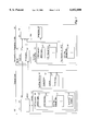
- FIG. 1 is a block diagram of the Extensible POST (E-POST) system of the present invention.
- FIG. 2 is a block diagram illustrating example contents of the various tables of the E-POST component and the Extensible External Status Monitor (EESM) component.
- EESM Extensible External Status Monitor
- FIG. 3 is a flow diagram of an implementation of the E-POST engine.
- FIG. 4 is a flow diagram of an implementation of the EESM engine.
- the present invention provides a method and system for monitoring the power-on self testing (POST) of a computer system in a way that allows new messages to be added without updating an external status monitor.
- POST power-on self testing
- This extensible system allows the external status monitor to support new messages for both new and existing POST tasks without requiring the external status monitor to be updated at the time the new messages are added.
- the Extensible POST (E-POST) system of the present invention includes an E-POST component and an Extensible External Status Monitor (EESM).
- EESM Extensible External Status Monitor
- the E-POST component When the E-POST component encounters a task with a new message, it notifies the EESM that a new message is coming and forwards the new message to the EESM. When the EESM receives the notification, it receives and displays the new message. If, however, the E-POST component encounters a task with an old message, the E-POST component merely forwards the token associated with the task to the EESM. If the EESM receives a token for a predefined message, then it retrieves that message from its POST Message Table and displays the retrieved message.
- New messages such as those associated with newly added tasks (“new tasks”)
- new tasks can in this way be defined and displayed without updating the external status monitor
- old messages for originally defined tasks
- the EESM has the speed advantages of the prior external status monitors when old messages are displayed and the flexibility to support new messages.
- FIG. 1 is a block diagram of the E-POST System of the present invention.
- the computer system 100 includes a CPU 110, a memory 115 containing the E-POST component 120, and input/output devices 130 including display device 131, keyboard 132, and storage device 133.
- the E-POST system comprises the E-POST component 120 and the Extensible External Status Monitor 150.
- the E-POST component includes the E-POST engine 121, the POST Task Table 122, the POST New Message Table 123, and POST task routines 124.
- the POST Task Table contains an entry for each old and new task to be performed during the POST. Each entry contains a unique token for the task and a reference to a routine that performs the task.
- the POST New Message Table contains an entry for each new message that is associated with a new or old task. Each entry in the POST New Message Table contains the unique token for the task and an associated message to be displayed for that task.
- the developer of the E-POST component adds a new task or associates a new message with an old task
- the developer adds an entry to the POST New Message Table. If a new task is being added, then the developer also adds a new entry containing the new token and a reference to the routine for the new task to the POST Task Table. If a new message is being associated with an old task, an old token is already associated with the old task in the POST Task Table. In one embodiment, the old token remains associated with the old task (and is thus used in the POST New Message Table entry for the new message).
- the developer overwrites the old token in the POST Task Table entry for the old task with a new token, thus associating the new token with the old task, and uses the new token in the POST New Message Table entry.
- the unique token that is associated with a task in the POST Task Table will be the same token used in the POST New Message Table with a new task message.
- the E-POST engine determines whether the task has a new message. If so, then the E-POST engine indicates to the EESM that a new message exists, and sends a token and the new message from the POST New Message Table entry for that task to the EESM. If the token is a new token, then the E-POST engine can indicate a new message merely by sending the new token (i.e., the EESM can recognize that the token is new). If the token is old (i.e. the old token has not been replaced with a new token), then the E-POST engine signals the EESM that a new message has been associated with an old token.
- the E-POST engine can set a flag that signals the EESM, or can send a ⁇ new message ⁇ token in place of the old token (if the ⁇ new message ⁇ token has been previously defined to indicate that a new message will follow).
- the E-POST engine sends only the old token from the POST Task Table to the EESM.
- the E-POST engine can determine whether a task has a new message by checking the POST New Message Table, and can determine whether a token is old or new in various ways.
- a POST Task Table entry could include a flag that indicated if a token is new (that would be set when an entry in the table was added or the token was modified).
- the developer could assign byte codes to new tokens that are distinguishable from the byte codes of old tokens.
- the EESM 150 includes the monitor 160, a CPU 165, a ROM 170, a display device 180, and an optional read-write memory 190.
- the monitor comprises the POST RAM 161 and index register 162.
- the ROM contains the EESM component, which includes the EESM Engine 171 and the POST Message Table 172.
- the POST Message Table contains an entry for each old token defined by the E-POST system, with each entry containing an old token and an associated old message.
- the E-POST engine could send a message notification flag along with the token when a new message is being sent, or the token itself could indicate that a new message is being sent (e.g., the token could be a previously defined ⁇ new message ⁇ token, or the absence of the token in the POST Message Table 172 could indicate that the token was new and a new message was being sent). If it is determined that a new message is not being sent, then the token is considered to be an old token. In this situation, the EESM engine retrieves the message from the POST Message Table that is associated with the old token, and displays the message on the display device.
- the EESM engine receives the message sent by the E-POST engine and displays that message on the display device. If the EESM contains an optional read-write memory and the EESM engine has received a new unique token, the EESM engine can dynamically create a POST New Message Table 191 by storing the new token and new message together. On subsequent performances of that task, the EESM engine can determine that the received new token is in the POST New Message Table and can retrieve the stored message from there rather than receiving the message from the E-POST engine.
- the E-POST engine If the E-POST engine is aware that the EESM engine contains such a POST New Message Table (e.g., through prior knowledge of the EESM engine's capabilities or through notification from the EESM engine), then the E-POST engine need only send a new message to the EESM engine once.
- the monitor 160 could physically reside either on the EESM 150 or on the computer system 100.
- FIG. 2 is a block diagram illustrating example contents of the various tables of the E-POST component and the EESM component.
- the POST Task Table 122 contains entries for five tasks.
- the tasks associated with tokens T1, T3, and T5 are old tasks with old messages, and the task associated with token T13 is a new task with a new message.
- the task that is associated with token T8 is an old task that now has a new message.
- the POST Task Table illustrates that the entry for each task includes a reference to a routine that is invoked to perform the task, such as the T1 routine 212.
- the POST Message Table 172 of the EESM contains an entry for each old message, identified by the old tokens T1, T3, T5, and T8.
- the developer of the E-POST system added a new entry to the POST Task Table and to the POST New Message Table 123.
- the developer added a new entry to the POST New Message Table along with the token associated with the task, token T8.
- the developer could have instead modified the existing task entry in the POST Task Table to change the token from T8 to some new unique token such as T20, and used the new token in the new POST New Message Table entry.
- the POST New Message Table thus contains an entry for each new message and its associated token.
- the developer did not need to update the POST Message Table of the EESM to reflect the changes made to the E-POST component. Instead, whenever the E-POST component performs a task with a new message, the E-POST engine indicates that a new message will be sent, and then sends the new message from the POST New Message Table to the EESM.
- the E-POST engine can indicate that a new message will be sent in a variety of ways. For a new token such as T13, sending the token can be a sufficient indication since the EESM can recognize that token T13 is new.
- the E-POST engine can send the old token as before and indicate a new message through the use of a flag, can substitute a predefined ⁇ new message ⁇ token (e.g., T00) for old token T8 when it is sent to the EESM, or can send both the old token and a ⁇ new message ⁇ token.
- a new token such as T13
- the EESM recognizes that a message corresponding to that token is not in its POST Message Table and that a new message will be sent.
- the EESM receives a new message indication through a flag or receives a ⁇ new message ⁇ token, the EESM knows that a new message will be sent.
- the EESM system is alerted to the existence of a new message, it then receives the message sent by the E-POST engine (e.g., "Perform RAM checksum" or "Autosize Memory") and displays that message.
- FIG. 3 is a flow diagram of an implementation of the E-POST engine.
- the E-POST engine loops retrieving each entry from the POST Task Table and invoking the routine identified by that entry.
- the E-POST engine also sends the token associated with the task in the retrieved table entry to the EESM. If the task has a new message, then the E-POST engine retrieves the associated message from the POST New Message Table and sends that message to the EESM.
- steps 301-308 the engine loops selecting and processing the entries from the POST Task Table.
- step 301 the engine selects the next entry from the POST Task Table, starting with the first entry.
- step 302 if the task of the selected entry has a new message, then the engine continues at step 303, else the engine continues at step 306.
- step 303 the engine retrieves the entry from the POST New Message Table associated with the token from the selected entry (i.e. that is associated with the selected task).
- step 304 the engine notifies the EESM that a new message will be sent. This can be accomplished by sending the new token or a ⁇ new message ⁇ token to the EESM, or by notifying the EESM such as through the use of a flag.
- step 305 the engine sends the new message from the retrieved POST New Message Table entry to the EESM.
- step 306 the engine sends the token from the selected POST Task Table entry to the EESM.
- step 307 the engine executes the routine associated with the selected POST Task Table entry.
- step 308 if all the POST tasks have already been selected from the POST Task Table, then the engine continues at step 309, and otherwise the engine loops to step 301 to select the next entry in the POST Task Table.
- step 309 the engine sends to the EESM an indication that the power-on self test is complete and the engine completes.
- FIG. 4 is a flow diagram of an implementation of the EESM engine.
- the engine loops retrieving tokens sent by the E-POST engine. If a retrieved token is a new token or if the EESM engine is notified that a new message is being sent, then the engine also retrieves the new message sent by the E-POST engine that follows the token. If the token is not a new token and there is no message notification, then the engine retrieves the old message associated with the token from the POST Message Table. The engine then displays on the display device either the message from the E-POST engine or from the POST Message Table.
- the EESM engine can determine that a new message will follow a token in a variety of ways.
- all tokens that are sent are old tokens, but old tokens with new messages are accompanied by a flag indicating the presence of the new message and the new message follows the token and flag.
- an old token with a new message is not sent to the EESM, but instead a predefined ⁇ new message ⁇ token is sent to indicate that a new message is following the token, and the EESM engine determines if the retrieved token is the predefined token.
- old tokens with new messages are replaced with new tokens, the new tokens and the new messages are sent to the EESM engine, and the engine recognizes new tokens by comparing the retrieved token to those in the POST Message Table and considering a token to be new if it is not in the table.
- step 401 the engine retrieves the last token sent by the E-POST engine by polling the POST RAM.
- step 402 if the retrieved token is not the same as the previously retrieved token, then the engine continues at step 403, else the engine loops back to step 401 to continue polling.
- step 403 if the retrieved POST token indicates that the power-on self test is complete, then the engine completes at step 408, else the engine continues at step 404.
- step 404 if the EESM receives an indication that a new message is being sent, then the engine continues at step 405, else the engine continues at step 406.
- step 405 the engine retrieves the message sent by the E-POST engine.
- step 406 the engine retrieves the message associated with the retrieved token from the POST Message Table.
- step 407 the engine displays the retrieved message on the display device and loops to step 401 to continue polling. If the EESM contains the optional read-write memory with a POST New Message Table, the engine can optionally include the additional steps (not shown) of associating a message retrieved in step 405 with the last token retrieved in step 401, and storing the token and message in the POST New Message Table.
- the E-POST system uses the monitor 160 in a way that solves a problem encountered by some prior POST systems.
- the monitor includes the POST RAM and the index register.
- the POST RAM typically contains a limited amount of RAM, and the index register contains a value that provides an index into the POST RAM.
- the LM78 contains 32 bytes of RAM and the index register contains a value between 0 and 31.
- the POST components write tokens associated with the tasks being performed during the power-on self test to a specified I/O port, such as I/O port address 80h.
- the monitor captures the tokens written to the specified I/O port, and writes the tokens to sequential locations in the POST RAM.
- the POST RAM has 32 bytes, then it can only store the first 32 1-byte tokens. Thus, such a prior POST component can only display messages for the first 32 tokens sent.
- the E-POST system uses the monitor in a way that allows an unlimited number of tokens to be sent to and received by the EESM and that allows new messages to be sent to the EESM. To accomplish this use, the E-POST component sets the value in the index register to point to a desired location (e.g., location 0) of the POST RAM. The E-POST component then writes the new token followed by the new message to the I/O port. As each byte of data is stored in the POST RAM, the index register is automatically incremented to point to the next location. Thus, the POST RAM will contain the new token followed by the new message in sequential locations.
- a desired location e.g., location 0
- an E-POST engine it is additionally possible for an E-POST engine to follow a procedure that allows it to function with both the EESM and prior external status monitors.
- the EESMs recognize two additional ports through which the E-POST can control the index register and store data in the POST RAM. Before each token is sent, the E-POST engine attempts to reset the index register to point to location 0 using one of the additional ports. The E-POST engine then writes the token to the byte indicated by the index register by writing to the other additional port. If the message is new, then the E-POST engine writes the message. Since prior external status monitors do not recognize those additional ports, they will ignore the data that supports the EESMs.
- the E-POST engine can also write the token to the specified I/O port that is supported by prior external status monitors. If an EESM is present, it will ignore the token written to the specified I/O port, and the EESM's functions will not be affected. If a prior external status monitor is instead present, it will ignore the initial token and message that are written, and will instead recognize only the token written to the specified I/O port. In this way, the E-POST engine can communicate with either EESMs or prior external status monitors.
Abstract
Description
Claims (13)
Priority Applications (1)
| Application Number | Priority Date | Filing Date | Title |
|---|---|---|---|
| US09/036,504 US6052800A (en) | 1998-03-06 | 1998-03-06 | Method and system for updating information on an intelligent display device monitoring a computer system |
Applications Claiming Priority (1)
| Application Number | Priority Date | Filing Date | Title |
|---|---|---|---|
| US09/036,504 US6052800A (en) | 1998-03-06 | 1998-03-06 | Method and system for updating information on an intelligent display device monitoring a computer system |
Publications (1)
| Publication Number | Publication Date |
|---|---|
| US6052800A true US6052800A (en) | 2000-04-18 |
Family
ID=21888943
Family Applications (1)
| Application Number | Title | Priority Date | Filing Date |
|---|---|---|---|
| US09/036,504 Expired - Lifetime US6052800A (en) | 1998-03-06 | 1998-03-06 | Method and system for updating information on an intelligent display device monitoring a computer system |
Country Status (1)
| Country | Link |
|---|---|
| US (1) | US6052800A (en) |
Cited By (13)
| Publication number | Priority date | Publication date | Assignee | Title |
|---|---|---|---|---|
| US20030110415A1 (en) * | 2001-11-02 | 2003-06-12 | Oleksandr Podgorsky | System and method for creating a customized Power On Self Test (POST) program for use in a computing system |
| US6647512B1 (en) * | 2000-09-29 | 2003-11-11 | Hewlett-Packard Development Company, L.P. | Method for restoring CMOS in a jumperless system |
| US20050096028A1 (en) * | 2000-05-08 | 2005-05-05 | Nokia Corporation | Method for over the air mobile station management |
| US6910157B1 (en) | 1999-07-16 | 2005-06-21 | Samsung Electronics Co., Ltd. | Portable computer system for indicating power-on self-test state on LED indicator |
| US7089494B1 (en) * | 2000-07-07 | 2006-08-08 | American Megatrends, Inc. | Data structure, methods, and computer program products for storing text data strings used to display text information on a display terminal |
| US20080022158A1 (en) * | 2006-07-20 | 2008-01-24 | Asustek Computer Inc. | Display system and method for displaying self-testing message |
| US20080077920A1 (en) * | 2006-09-21 | 2008-03-27 | Andreas Faatz | System for suggesting training |
| US20080294939A1 (en) * | 2007-05-22 | 2008-11-27 | Hong Fu Jin Precision Industry (Shenzhen) Co., Ltd. | Debugging device and method using the lpc/pci bus |
| US20100162048A1 (en) * | 2008-12-24 | 2010-06-24 | Samsung Electronics Co. Ltd. | Apparatus and method for automatic self-diagnosis using universal serial bus port in digital equipment |
| US8752038B1 (en) * | 2008-03-17 | 2014-06-10 | Symantec Corporation | Reducing boot time by providing quantitative performance cost data within a boot management user interface |
| US10083101B2 (en) * | 2015-11-04 | 2018-09-25 | Nuvoton Technology Corporation | Computer status diagnosis chip and computer status diagnosis system including the same |
| US10592256B2 (en) * | 2018-05-01 | 2020-03-17 | Dell Products L.P. | Early boot display system |
| CN112463094A (en) * | 2020-11-30 | 2021-03-09 | 中国航空工业集团公司西安航空计算技术研究所 | General cockpit control cabinet state comprehensive display device |
Citations (4)
| Publication number | Priority date | Publication date | Assignee | Title |
|---|---|---|---|---|
| US5519832A (en) * | 1992-11-13 | 1996-05-21 | Digital Equipment Corporation | Method and apparatus for displaying module diagnostic results |
| US5630048A (en) * | 1994-05-19 | 1997-05-13 | La Joie; Leslie T. | Diagnostic system for run-time monitoring of computer operations |
| US5761505A (en) * | 1995-11-17 | 1998-06-02 | Hewlett-Packard Co. | System and method for automatically and reliably managing global resources in a computer network |
| US5930503A (en) * | 1995-12-29 | 1999-07-27 | Hewlett-Packard Co | System and method for on demand registration of tasks |
-
1998
- 1998-03-06 US US09/036,504 patent/US6052800A/en not_active Expired - Lifetime
Patent Citations (5)
| Publication number | Priority date | Publication date | Assignee | Title |
|---|---|---|---|---|
| US5519832A (en) * | 1992-11-13 | 1996-05-21 | Digital Equipment Corporation | Method and apparatus for displaying module diagnostic results |
| US5630048A (en) * | 1994-05-19 | 1997-05-13 | La Joie; Leslie T. | Diagnostic system for run-time monitoring of computer operations |
| US5933594A (en) * | 1994-05-19 | 1999-08-03 | La Joie; Leslie T. | Diagnostic system for run-time monitoring of computer operations |
| US5761505A (en) * | 1995-11-17 | 1998-06-02 | Hewlett-Packard Co. | System and method for automatically and reliably managing global resources in a computer network |
| US5930503A (en) * | 1995-12-29 | 1999-07-27 | Hewlett-Packard Co | System and method for on demand registration of tasks |
Non-Patent Citations (4)
| Title |
|---|
| "Microprocessor System Hardware Monitor", National Semiconductor Product Folder, pp. 1-2, http://www.national.com/pf/LM/LM78.html, (Information as of Jul. 7, 1998) (visited Jul. 8, 1998). |
| "Microprocessor System Hardware Monitor", National Semiconductor, pp. 1-31, http://www.national.com/ds/LM/LM78.pdf, Mar. 1998, (visited Jul. 8, 1998). |
| Microprocessor System Hardware Monitor , National Semiconductor Product Folder, pp. 1 2, http://www.national.com/pf/LM/LM78.html, (Information as of Jul. 7, 1998) (visited Jul. 8, 1998). * |
| Microprocessor System Hardware Monitor , National Semiconductor, pp. 1 31, http://www.national.com/ds/LM/LM78.pdf, Mar. 1998, (visited Jul. 8, 1998). * |
Cited By (16)
| Publication number | Priority date | Publication date | Assignee | Title |
|---|---|---|---|---|
| US6910157B1 (en) | 1999-07-16 | 2005-06-21 | Samsung Electronics Co., Ltd. | Portable computer system for indicating power-on self-test state on LED indicator |
| US20050096028A1 (en) * | 2000-05-08 | 2005-05-05 | Nokia Corporation | Method for over the air mobile station management |
| US7089494B1 (en) * | 2000-07-07 | 2006-08-08 | American Megatrends, Inc. | Data structure, methods, and computer program products for storing text data strings used to display text information on a display terminal |
| US6647512B1 (en) * | 2000-09-29 | 2003-11-11 | Hewlett-Packard Development Company, L.P. | Method for restoring CMOS in a jumperless system |
| US20040073842A1 (en) * | 2000-09-29 | 2004-04-15 | James Don R. | Method for restoring CMOS in a jumperless system |
| US7069472B2 (en) | 2000-09-29 | 2006-06-27 | Hewlett-Packard Development Company, L.P. | Method for restoring CMOS in a jumperless system |
| US20030110415A1 (en) * | 2001-11-02 | 2003-06-12 | Oleksandr Podgorsky | System and method for creating a customized Power On Self Test (POST) program for use in a computing system |
| US6976188B2 (en) * | 2001-11-02 | 2005-12-13 | American Megatrends, Inc. | System and method for creating a customized power on self test (POST) program for use in a computing system |
| US20080022158A1 (en) * | 2006-07-20 | 2008-01-24 | Asustek Computer Inc. | Display system and method for displaying self-testing message |
| US20080077920A1 (en) * | 2006-09-21 | 2008-03-27 | Andreas Faatz | System for suggesting training |
| US20080294939A1 (en) * | 2007-05-22 | 2008-11-27 | Hong Fu Jin Precision Industry (Shenzhen) Co., Ltd. | Debugging device and method using the lpc/pci bus |
| US8752038B1 (en) * | 2008-03-17 | 2014-06-10 | Symantec Corporation | Reducing boot time by providing quantitative performance cost data within a boot management user interface |
| US20100162048A1 (en) * | 2008-12-24 | 2010-06-24 | Samsung Electronics Co. Ltd. | Apparatus and method for automatic self-diagnosis using universal serial bus port in digital equipment |
| US10083101B2 (en) * | 2015-11-04 | 2018-09-25 | Nuvoton Technology Corporation | Computer status diagnosis chip and computer status diagnosis system including the same |
| US10592256B2 (en) * | 2018-05-01 | 2020-03-17 | Dell Products L.P. | Early boot display system |
| CN112463094A (en) * | 2020-11-30 | 2021-03-09 | 中国航空工业集团公司西安航空计算技术研究所 | General cockpit control cabinet state comprehensive display device |
Similar Documents
| Publication | Publication Date | Title |
|---|---|---|
| US5634137A (en) | Method and apparatus for updating system configuration based on open/closed state of computer housing cover | |
| US5748980A (en) | System for configuring a computer system | |
| US5325532A (en) | Automatic development of operating system boot image | |
| US6725178B2 (en) | Use of hidden partitions in a storage device for storing BIOS extension files | |
| US7103641B2 (en) | Method and apparatus for distributing computer platform firmware across a network | |
| US6336152B1 (en) | Method for automatically configuring devices including a network adapter without manual intervention and without prior configuration information | |
| US6052800A (en) | Method and system for updating information on an intelligent display device monitoring a computer system | |
| US5768568A (en) | System and method for initializing an information processing system | |
| US5953010A (en) | User-friendly iconic message display indicating progress and status of loading and running system program in electronic digital computer | |
| US5819107A (en) | Method for managing the assignment of device drivers in a computer system | |
| US5854905A (en) | Extensible bios for boot support of devices on multiple hierarchical buses | |
| US8468333B1 (en) | Updating the system management information of a computer system | |
| US5193174A (en) | System for automatically redirecting information to alternate system console in response to the comparison of present and default system configuration in personal computer system | |
| US20040230963A1 (en) | Method for updating firmware in an operating system agnostic manner | |
| US20060236087A1 (en) | Apparatus and method for testing computer system | |
| US20030069999A1 (en) | Method for providing a single preloaded software image with an ability to support multiple hardware configurations and multiple types of computer systems | |
| JPH06324849A (en) | Method and system for activation of operating system environment | |
| HUT57919A (en) | Method and circuit arrangement for loading operation systems into computers | |
| US20040267708A1 (en) | Device information collection and error detection in a pre-boot environment of a computer system | |
| US6813669B1 (en) | Agent provided by USB device for executing USB device dependent program in USB host | |
| US6393559B1 (en) | Method and computer for self-healing BIOS initialization code | |
| JPH0644063A (en) | Method of integrating individual subprogram to main program | |
| JPH0695838A (en) | Connecting mechanism of display monitor for computer system and connection supporting method | |
| WO2004010295A2 (en) | Method and apparatus for instrumentation on/off | |
| US20030172320A1 (en) | System and method for system surveillance using firmware progress code |
Legal Events
| Date | Code | Title | Description |
|---|---|---|---|
| AS | Assignment |
Owner name: MICRON ELECTRONICS, INC., IDAHO Free format text: ASSIGNMENT OF ASSIGNORS INTEREST;ASSIGNORS:GENTILE, ROBERT;ANDERSON, ERIC D.;REEL/FRAME:009610/0163;SIGNING DATES FROM 19980903 TO 19981118 |
|
| STCF | Information on status: patent grant |
Free format text: PATENTED CASE |
|
| AS | Assignment |
Owner name: MEI CALIFORNIA, INC., CALIFORNIA Free format text: ASSIGNMENT OF ASSIGNORS INTEREST;ASSIGNOR:MICRON ELECTRONICS, INC.;REEL/FRAME:011658/0956 Effective date: 20010322 |
|
| FPAY | Fee payment |
Year of fee payment: 4 |
|
| FPAY | Fee payment |
Year of fee payment: 8 |
|
| FPAY | Fee payment |
Year of fee payment: 12 |
|
| AS | Assignment |
Owner name: U.S. BANK NATIONAL ASSOCIATION, AS COLLATERAL AGENT, CALIFORNIA Free format text: SECURITY INTEREST;ASSIGNOR:MICRON TECHNOLOGY, INC.;REEL/FRAME:038669/0001 Effective date: 20160426 Owner name: U.S. BANK NATIONAL ASSOCIATION, AS COLLATERAL AGEN Free format text: SECURITY INTEREST;ASSIGNOR:MICRON TECHNOLOGY, INC.;REEL/FRAME:038669/0001 Effective date: 20160426 |
|
| AS | Assignment |
Owner name: MORGAN STANLEY SENIOR FUNDING, INC., AS COLLATERAL AGENT, MARYLAND Free format text: PATENT SECURITY AGREEMENT;ASSIGNOR:MICRON TECHNOLOGY, INC.;REEL/FRAME:038954/0001 Effective date: 20160426 Owner name: MORGAN STANLEY SENIOR FUNDING, INC., AS COLLATERAL Free format text: PATENT SECURITY AGREEMENT;ASSIGNOR:MICRON TECHNOLOGY, INC.;REEL/FRAME:038954/0001 Effective date: 20160426 |
|
| AS | Assignment |
Owner name: U.S. BANK NATIONAL ASSOCIATION, AS COLLATERAL AGENT, CALIFORNIA Free format text: CORRECTIVE ASSIGNMENT TO CORRECT THE REPLACE ERRONEOUSLY FILED PATENT #7358718 WITH THE CORRECT PATENT #7358178 PREVIOUSLY RECORDED ON REEL 038669 FRAME 0001. ASSIGNOR(S) HEREBY CONFIRMS THE SECURITY INTEREST;ASSIGNOR:MICRON TECHNOLOGY, INC.;REEL/FRAME:043079/0001 Effective date: 20160426 Owner name: U.S. BANK NATIONAL ASSOCIATION, AS COLLATERAL AGEN Free format text: CORRECTIVE ASSIGNMENT TO CORRECT THE REPLACE ERRONEOUSLY FILED PATENT #7358718 WITH THE CORRECT PATENT #7358178 PREVIOUSLY RECORDED ON REEL 038669 FRAME 0001. ASSIGNOR(S) HEREBY CONFIRMS THE SECURITY INTEREST;ASSIGNOR:MICRON TECHNOLOGY, INC.;REEL/FRAME:043079/0001 Effective date: 20160426 |
|
| AS | Assignment |
Owner name: MICRON TECHNOLOGY, INC., IDAHO Free format text: RELEASE BY SECURED PARTY;ASSIGNOR:U.S. BANK NATIONAL ASSOCIATION, AS COLLATERAL AGENT;REEL/FRAME:047243/0001 Effective date: 20180629 |
|
| AS | Assignment |
Owner name: MICRON TECHNOLOGY, INC., IDAHO Free format text: RELEASE BY SECURED PARTY;ASSIGNOR:MORGAN STANLEY SENIOR FUNDING, INC., AS COLLATERAL AGENT;REEL/FRAME:050937/0001 Effective date: 20190731 |