US6054036A - Electrophoresis gels and gel holders having fiber spacers and method of making same - Google Patents
Electrophoresis gels and gel holders having fiber spacers and method of making same Download PDFInfo
- Publication number
- US6054036A US6054036A US09/077,304 US7730498A US6054036A US 6054036 A US6054036 A US 6054036A US 7730498 A US7730498 A US 7730498A US 6054036 A US6054036 A US 6054036A
- Authority
- US
- United States
- Prior art keywords
- gel
- fibers
- substrate
- substrates
- excitation
- Prior art date
- Legal status (The legal status is an assumption and is not a legal conclusion. Google has not performed a legal analysis and makes no representation as to the accuracy of the status listed.)
- Expired - Fee Related
Links
Images


Classifications
-
- G—PHYSICS
- G01—MEASURING; TESTING
- G01N—INVESTIGATING OR ANALYSING MATERIALS BY DETERMINING THEIR CHEMICAL OR PHYSICAL PROPERTIES
- G01N27/00—Investigating or analysing materials by the use of electric, electrochemical, or magnetic means
- G01N27/26—Investigating or analysing materials by the use of electric, electrochemical, or magnetic means by investigating electrochemical variables; by using electrolysis or electrophoresis
- G01N27/416—Systems
- G01N27/447—Systems using electrophoresis
- G01N27/44704—Details; Accessories
- G01N27/44717—Arrangements for investigating the separated zones, e.g. localising zones
- G01N27/44721—Arrangements for investigating the separated zones, e.g. localising zones by optical means
-
- G—PHYSICS
- G01—MEASURING; TESTING
- G01N—INVESTIGATING OR ANALYSING MATERIALS BY DETERMINING THEIR CHEMICAL OR PHYSICAL PROPERTIES
- G01N27/00—Investigating or analysing materials by the use of electric, electrochemical, or magnetic means
- G01N27/26—Investigating or analysing materials by the use of electric, electrochemical, or magnetic means by investigating electrochemical variables; by using electrolysis or electrophoresis
- G01N27/416—Systems
- G01N27/447—Systems using electrophoresis
- G01N27/44704—Details; Accessories
Definitions
- DNA sequencing may be carried out using automated systems designed for laboratory application. Methods and apparatus for sequencing of DNA are described in U.S. Pat. Nos. 4,811,218; 4,823,007; 5,062,942; 5,091,652; 5,119,316 and 5,122,345, which are incorporated herein by reference.
- the general methodology employed in these systems involves breaking up the sample DNA using restriction endonucleases; amplifying (for example with PCR) the restriction fragment of interest; combining the amplified DNA with a sequencing primer which may be the same as or different from the amplification primers; extending the sequencing primer in the presence of normal nucleotide (A, C, G, and T) and a chain-terminating nucleotide, such as a dideoxynucleotide, which prevents further extension of the primer once incorporated; and analyzing the product for the length of the extended fragments obtained. Analysis of fragments may be done by electrophoresis, for example on a polyacrylamide gel.
- the characteristics of the gel impact the time and cost required to do the analysis. Since it is desirable to reduce the time and cost of sequencing analyses in order to improve the available of sequencing as a diagnostic tool, it would be advantageous to have a gel which permitted analysis of very small quantities of oligonucleotide fragments in a short period of time. It would further be advantageous to have a disposable, single use gel holder which could be manufactured on a large scale which when filled with a gel would provide these desirable characteristics.
- It an object of the present invention to provide disposable, single use gel holders having a very thin gel chamber of uniform thickness, which can be easily manufactured.
- one aspect of the invention is a method comprising the steps of:
- a plurality of fibers disposed between the first and second planar substrates.
- the fibers are adhered to the first and second planar substrates with a melt-flowed substance having a lower melting temperature than the fibers so that the fibers and the first and second planar substrates, in concert, define a gel chamber having a thickness defined by the diameter of the fibers.
- this chamber is filled with a polymerized gel such as a polyacrylamide gel.
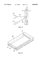
- FIGS. 1A and 1B shows a first embodiment of a gel holder in accordance with the present invention
- FIG. 2 shows an end view of a gel holder in accordance with the invention
- FIG. 3 shows two-layer fibers useful in the present invention
- FIG. 4 shows an embodiment of the invention useful in apparatus where the interrogating beam and the detection system are on the same side of the gel
- FIG. 5 shows an electrophoresis gel according to the invention
- FIGS. 6A and 6B show the use of thin regions in gel holders according to the invention.
- FIGS. 7A and 7B show construction alternatives for substrates with thin regions.
- FIG. 8 shows the use of a laser to heat the exterior cladding of a fiber in a method according to the invention.
- FIG. 1 shows a first embodiment of a gel holder in accordance with the present invention.
- the gel holder is formed from a top substrate 10, a bottom substrate 11 and a plurality of fibers 12.
- the fibers 12 are disposed parallel to one another and to opposing edges of the substrates 10, 11 and extend from one end of the substrates to the other.
- the bottom substrate 11 may extend beyond the top substrate 10 at one end of the gel holder as shown to facilitate loading of electrophoresis samples, in which case the fibers may end even with the top substrate or extend out onto the bottom substrate as shown in FIG. 1A.
- an opening 13 may be cut near one end of the top substrate for this purpose. (FIG. 1B).
- FIG. 2 shows the bottom end of a gel holder having two fibers rather than the four shown in FIG. 1 in greater detail.
- the fibers 12 are in contact with the top and bottom substrates 10, 11, and are adhered to the substrates with a melt-flowed substance 21.
- the fibers 12 and the top and bottom substrates 10, 11 in concert define a chamber 20 which is filled with an electrophoresis gel.
- melt-flowed substance refers to a material which has been at least softened and preferably melted to allow it to conform to the shape of surrounding unmelted materials, and then resolidified in the conformed shape to adhere the surrounding objects together.
- the gel holder of the invention can be made by using fibers as shown in FIG. 3 having an interior core 31 having a first melting point and an external cladding 32 having a second melting point lower than the first melting point.
- the fibers may have a circular cross-section as shown in FIG. 3, or other shapes including ovoid and rectangular.
- the fibers are glass fibers.
- the interior core is suitably made from glass having a melting point of from 600 to 800° C.
- the exterior cladding is made from glass having a melting point of from 400 to 500° C. It will be appreciated, however, that other materials can be used for either the core fiber or the external cladding, or both.
- the core fiber can be made from glass, quartz or any polymer with a sufficiently higher melting point then the external cladding, such that the external cladding will melt while the core does not.
- the external cladding may be made of glass or a polymer, for example plastics, provided that the material does not negatively impact on the ability of a gel to polymerize within the chamber or fluoresce strongly at the wavelength used for detection of separated materials during or after electrophoresis.
- the coefficients of thermal expansion of the interior core 31 and the exterior cladding 32 are closely matched to reduce cracking or other deformations upon cooling.
- the coefficients of thermal expansion are within 10% of each other. More preferably, the coefficients of thermal expansion are within 1% of each other.
- the substrates used in forming the gel holders of the present invention may be any flat, planar material which is compatible with the electrophoresis gel and the method of detection to be employed.
- plastic materials which do not interfere with the polymerization of the electrophoresis gel or the observation of the separated fragments on the electrophoresis gel can be used.
- the substrates are made from glass, and most preferably from low-fluorescing glass. 1 mm Borosilicate glass which has greater ultraviolet light transparency is another preferred material.
- At least one of the substrates used in forming the gel holder of the invention must be made from a material which will permit observation of the materials separated within the electrophoresis gel.
- the interrogating beam source for example a laser 41 producing a beam of light 42 for exciting fluorescent molecules in the gel 43, and the detector 44 for detecting emitted light 45 are located in the same side of the electrophoresis gel as shown in FIG. 4.
- the bottom substrate 11 can be selected to minimize any contribution to background radiation rather than for its ability to permit observation of the sample.
- the bottom substrate 11 can be made from a colored glass which absorbs all of the exciting light which reaches it, and which thus is essentially non-fluorescent. Since background fluorescence arises in large part from fluorescent impurities in the substrates, this can substantially reduce the amount of background fluorescence and improve the sensitivity of the observations.
- one substrate 50 can be made of thicker (and preferably absorbing and non-fluorescing) material while the other substrate 51 is made of a very thin (i.e., 0.1 mm or less) transparent, low fluorescing material. Suitable thin materials include "cover slip" glass.
- the thin region 61 may also be localized to just an excitation/detection zone running perpendicular to the fibers as shown in FIG. 6A, or cover one edge of the gel as shown in FIG. 6B.
- Such substrates can be formed by molding a contiguous substrate into the desired shape (FIG.
- the blocks 71 of thicker material may also be formed from absorbing, non-fluorescing materials to further reduce background fluorescence.
- the fibers are first placed onto a surface of one of the substrates.
- the substrates should be aligned parallel to one another and parallel to two opposing edges of the substrate.
- Fibers can be placed in a frame which will keep them parallel to each other and positioned at a certain distance from each other. If two fibers are used, they are advantageously placed near the edges of the substrate, thus creating one large gel chamber in the interior. More than two fibers may be used, in which case the gel chamber is divided into several parts. In this instance, fibers are preferably placed at intervals such that each part of the chamber is large enough to receive four samples, i.e., one sample lane for each chain terminating oligonucleotide mixture used in the sequencing process.
- a total of five fibers would be used.
- the use of more than two fibers is particularly suitable for wider gels since the interior fibers help prevent sagging of the substrate in the middle of the gel chamber and thus define a gel chamber of more consistent width.
- the next step is to place the second substrate over the fibers to form a sandwich structure in which the fibers are disposed between the two substrates.
- the sandwich is then heated, for example in an oven, to soften or melt the cladding on the fiber while pressure is applied to the exterior of the sandwich.
- the interior cores of the fibers are pressed into intimate contact with the substrates while the softened exterior cladding flows to fill the space around the fiber.
- the melt-flowed cladding material adheres the fibers to the substrates to form a gel holder. Fibers which extend beyond the edge of the sandwich can be trimmed off with clippers or by other means.
- the exterior cladding of the fibers is softened or melted prior to placing the second substrate over the fibers.
- a CO 2 laser 81 emits light 82 which is focused by lens 83 to heat the exterior cladding 32.
- the second substrate is then placed on top of the partially melted fibers, and the substrates are pressed together and allowed to cool.
- the cladding may be melted using radio frequency or microwave radiation.
- the size of the gel chamber in the gel holders of the invention is determined by the thickness of the interior core of the fibers.
- these fibers will preferably have a diameter of 250 microns or less, and most preferably of 50 to 100 microns.
- the lower limit is fixed only by the ability to obtain a very thin fiber of consistent core diameter and the ability to uniformly introduce a gel forming solution without bubble formation into significantly smaller gaps.
- the present invention provides a very facile way to achieve very small spacings between the substrates, regardless of the size of the gap.
- the method of the invention can be used to make gel holders having a larger gap. Such gel holders are not as well suited to high speed analysis of nucleic acid fragments, however.
- the thickness of the exterior cladding is not critical provided that it contains enough material to adhere the fiber to the substrate(s) and is not so large as to block significant portions of the gel chamber. In general, claddings which are 5 to 10 microns thick are suitable.
- the next steps are the filling of the chamber with a gel forming solution and the polymerization of the solution to form a gel.
- This process can be performed in any of a number of ways which will be apparent to persons skilled in the art.
- the gel holder is filled using an apparatus of the type described in U.S. patent application Ser. No. 08/332,892, filed Nov. 1, 1994, and International Patent Application No. PCT/US95/13954 filed Oct. 31, 1995 and published as WO 96/13715, which applications are incorporated herein by reference.
- the gel is placed in the chamber prior to the application of the second substrate over the fibers.
- the fibers are placed over the first substrate, which may be light absorbing and non-fluorescing, and heated to adhere them to the substrate.
- a gel forming solution is then poured onto the substrate to essentially the same depth as the fibers and polymerized under an inert gas, e.g., nitrogen or argon.
- Temporary glass plates may be attached from the sides to prevent the gel from running off.
- a frame may be used which tightly seals the edges into which the bottom substrate is positioned before and during the polymerization process.
- this method provides a gel with very uniform thickness.
- a very thin (i.e,. 1 to 10 microns), flexible and transparent film is laid onto the top of the gel and secured by adhesive or mechanical means.
- Suitable materials for use as the cover film include any dissolved polymers, and particularly those which are sprayable. These polymer films will not affect polymerization of the gel, since the process of polymerization is finished before the film is attached.
- the gel holders and electrophoresis gels of the present invention provide several advantages over the prior art. First, they are easy to manufacture, and can be prepared as disposable units for later filling with an electrophoresis gel. Second, they provide highly uniform spacing between the substrates. In addition, because the melt-flowed material is molded into shape thermally, materials such as glass which do not interfere with the polymerization of the gel or fluoresce strongly can be used to adhere the gel holders together.
Abstract
Description
Claims (4)
Priority Applications (1)
| Application Number | Priority Date | Filing Date | Title |
|---|---|---|---|
| US09/077,304 US6054036A (en) | 1995-12-12 | 1996-12-12 | Electrophoresis gels and gel holders having fiber spacers and method of making same |
Applications Claiming Priority (3)
| Application Number | Priority Date | Filing Date | Title |
|---|---|---|---|
| US08/571,297 US5618398A (en) | 1995-12-12 | 1995-12-12 | Electrophoresis gels and gel holders having fiber spacers and method of making same |
| PCT/CA1996/000832 WO1997021995A1 (en) | 1995-12-12 | 1996-12-12 | Electrophoresis gels and gel holders having fiber spacers and method of making same |
| US09/077,304 US6054036A (en) | 1995-12-12 | 1996-12-12 | Electrophoresis gels and gel holders having fiber spacers and method of making same |
Related Parent Applications (1)
| Application Number | Title | Priority Date | Filing Date |
|---|---|---|---|
| US08/571,297 Continuation-In-Part US5618398A (en) | 1995-12-12 | 1995-12-12 | Electrophoresis gels and gel holders having fiber spacers and method of making same |
Publications (1)
| Publication Number | Publication Date |
|---|---|
| US6054036A true US6054036A (en) | 2000-04-25 |
Family
ID=24283096
Family Applications (2)
| Application Number | Title | Priority Date | Filing Date |
|---|---|---|---|
| US08/571,297 Expired - Lifetime US5618398A (en) | 1995-12-12 | 1995-12-12 | Electrophoresis gels and gel holders having fiber spacers and method of making same |
| US09/077,304 Expired - Fee Related US6054036A (en) | 1995-12-12 | 1996-12-12 | Electrophoresis gels and gel holders having fiber spacers and method of making same |
Family Applications Before (1)
| Application Number | Title | Priority Date | Filing Date |
|---|---|---|---|
| US08/571,297 Expired - Lifetime US5618398A (en) | 1995-12-12 | 1995-12-12 | Electrophoresis gels and gel holders having fiber spacers and method of making same |
Country Status (6)
| Country | Link |
|---|---|
| US (2) | US5618398A (en) |
| EP (2) | EP0866962A1 (en) |
| JP (1) | JP2000505189A (en) |
| AU (1) | AU710328B2 (en) |
| CA (1) | CA2239988A1 (en) |
| WO (1) | WO1997021995A1 (en) |
Cited By (3)
| Publication number | Priority date | Publication date | Assignee | Title |
|---|---|---|---|---|
| US20030000839A1 (en) * | 1999-04-06 | 2003-01-02 | Manusu Howard Pericles | Cassette for electrophoretic gels |
| US6582577B1 (en) * | 2000-08-31 | 2003-06-24 | Visible Genetics Inc. | Electrophoresis gel cassette |
| US20080128280A1 (en) * | 2004-11-25 | 2008-06-05 | Ge Healthcare Bio-Sciences Ab | Method For Scanning Gels And Gel Folder For Use In The Method |
Families Citing this family (2)
| Publication number | Priority date | Publication date | Assignee | Title |
|---|---|---|---|---|
| WO2001027599A1 (en) * | 1999-10-13 | 2001-04-19 | Genomic Solutions Inc. | A system for minimizing background fluorescence in fluorescence imaging applications using neutral density filter material substrates |
| JP2007039106A (en) * | 2005-08-04 | 2007-02-15 | Sii Nanotechnology Inc | Thin small sheet chip holder using elastic material |
Citations (31)
| Publication number | Priority date | Publication date | Assignee | Title |
|---|---|---|---|---|
| US3663395A (en) * | 1969-12-17 | 1972-05-16 | Beckman Instruments Inc | Cross-section illuminator for a continuous particle electrophoresis cell |
| US4704198A (en) * | 1984-04-27 | 1987-11-03 | E. I. Du Pont De Nemours And Company | Porosity gradient electrophoresis gel |
| US4790919A (en) * | 1984-06-28 | 1988-12-13 | E. I. Du Pont De Nemours And Company | Process for preparation of electrophoresis gel material |
| EP0294524A1 (en) * | 1987-06-09 | 1988-12-14 | The Perkin-Elmer Corporation | Real time scanning electrophoresis apparatus for DNA sequencing |
| US4811218A (en) * | 1986-06-02 | 1989-03-07 | Applied Biosystems, Inc. | Real time scanning electrophoresis apparatus for DNA sequencing |
| US4823077A (en) * | 1986-11-10 | 1989-04-18 | Hewlett-Packard Company | Channel-gain-vernier-tracking trigger hysteresis for an oscilloscope |
| US4863647A (en) * | 1984-06-28 | 1989-09-05 | Baylor Jr Charles | Process for preparation of electrophoresis gel material |
| US4919784A (en) * | 1989-08-16 | 1990-04-24 | Eg&G, Inc. | Electrophorresis cassette spacer |
| US4929329A (en) * | 1987-04-27 | 1990-05-29 | Eg&G, Inc. | Electrophoresis cassette system with apparatus and method for filling same |
| EP0404646A1 (en) * | 1989-06-21 | 1990-12-27 | Zeta Technology | Electrophoretic capillary with incorporated optical system |
| US5047135A (en) * | 1988-03-22 | 1991-09-10 | Erik Nieman | Electrophoresis apparatus |
| US5062942A (en) * | 1989-04-12 | 1991-11-05 | Hitachi, Ltd. | Fluorescence detection type electrophoresis apparatus |
| US5071531A (en) * | 1989-05-01 | 1991-12-10 | Soane Technologies, Inc. | Casting of gradient gels |
| US5073246A (en) * | 1990-05-16 | 1991-12-17 | Bio-Rad Laboratories, Inc. | Slab electrophoresis system with improved sample wells and cooling mechanism |
| US5091652A (en) * | 1990-01-12 | 1992-02-25 | The Regents Of The University Of California | Laser excited confocal microscope fluorescence scanner and method |
| US5092973A (en) * | 1990-01-26 | 1992-03-03 | The Board Of Trustees Of The Leland Stanford Junior University | Rectangular capillaries for capillary electrophoresis |
| US5108179A (en) * | 1989-08-09 | 1992-04-28 | Myers Stephen A | System and method for determining changes in fluorescence of stained nucleic acid in electrophoretically separated bands |
| US5119316A (en) * | 1990-06-29 | 1992-06-02 | E. I. Du Pont De Nemours And Company | Method for determining dna sequences |
| US5122345A (en) * | 1988-07-12 | 1992-06-16 | President And Fellows Of Harvard College | Dna sequencing apparatus |
| US5141868A (en) * | 1984-06-13 | 1992-08-25 | Internationale Octrooi Maatschappij "Octropa" Bv | Device for use in chemical test procedures |
| EP0504943A2 (en) * | 1991-03-22 | 1992-09-23 | Hitachi Software Engineering Co., Ltd. | Multi-colored electrophoresis pattern reading system |
| US5164066A (en) * | 1987-04-27 | 1992-11-17 | Eg&G Inc. | Electrophoresis cassette system with apparatus and method for filling same |
| US5186807A (en) * | 1991-08-13 | 1993-02-16 | Erie Scientific Company | Electrophoresis gel slab cassettes having pull cords and methods |
| US5192408A (en) * | 1991-08-27 | 1993-03-09 | Cbs Scientific, Inc. | Electrophoresis gel sealing gasket and system |
| US5192412A (en) * | 1990-11-30 | 1993-03-09 | Hitachi, Ltd. | Electrophoretic apparatus having arrayed electrophoresis lanes |
| EP0534135A1 (en) * | 1991-09-13 | 1993-03-31 | Oxford Glycosystems Ltd. | Gel electrophoresis cassette |
| US5202010A (en) * | 1987-11-25 | 1993-04-13 | Princeton Biochemicals, Inc. | Automated capillary electrophoresis apparatus |
| US5209831A (en) * | 1991-06-14 | 1993-05-11 | Macconnell William P | Bufferless electrophoresis system and method |
| US5324401A (en) * | 1993-02-05 | 1994-06-28 | Iowa State University Research Foundation, Inc. | Multiplexed fluorescence detector system for capillary electrophoresis |
| US5338426A (en) * | 1992-08-28 | 1994-08-16 | Applied Biosystems, Inc. | Horizontal polyacrylamide gel electrophoresis |
| US5356776A (en) * | 1991-09-10 | 1994-10-18 | Hitachi, Ltd. | DNA measuring method |
Family Cites Families (3)
| Publication number | Priority date | Publication date | Assignee | Title |
|---|---|---|---|---|
| US4823007A (en) * | 1986-12-15 | 1989-04-18 | Norand Corporation | DNA sequencing gel reading system and method |
| GB9115073D0 (en) * | 1991-07-12 | 1991-08-28 | Astromed Ltd | Improvements in electrophoretic separation |
| JPH06141956A (en) * | 1992-11-09 | 1994-05-24 | Tadashi Iura | Handrail device for handicapped person |
-
1995
- 1995-12-12 US US08/571,297 patent/US5618398A/en not_active Expired - Lifetime
-
1996
- 1996-12-12 EP EP96940960A patent/EP0866962A1/en not_active Withdrawn
- 1996-12-12 JP JP09521569A patent/JP2000505189A/en active Pending
- 1996-12-12 CA CA002239988A patent/CA2239988A1/en not_active Abandoned
- 1996-12-12 WO PCT/CA1996/000832 patent/WO1997021995A1/en not_active Application Discontinuation
- 1996-12-12 US US09/077,304 patent/US6054036A/en not_active Expired - Fee Related
- 1996-12-12 EP EP20000201823 patent/EP1046907A2/en not_active Withdrawn
- 1996-12-12 AU AU10274/97A patent/AU710328B2/en not_active Ceased
Patent Citations (31)
| Publication number | Priority date | Publication date | Assignee | Title |
|---|---|---|---|---|
| US3663395A (en) * | 1969-12-17 | 1972-05-16 | Beckman Instruments Inc | Cross-section illuminator for a continuous particle electrophoresis cell |
| US4704198A (en) * | 1984-04-27 | 1987-11-03 | E. I. Du Pont De Nemours And Company | Porosity gradient electrophoresis gel |
| US5141868A (en) * | 1984-06-13 | 1992-08-25 | Internationale Octrooi Maatschappij "Octropa" Bv | Device for use in chemical test procedures |
| US4790919A (en) * | 1984-06-28 | 1988-12-13 | E. I. Du Pont De Nemours And Company | Process for preparation of electrophoresis gel material |
| US4863647A (en) * | 1984-06-28 | 1989-09-05 | Baylor Jr Charles | Process for preparation of electrophoresis gel material |
| US4811218A (en) * | 1986-06-02 | 1989-03-07 | Applied Biosystems, Inc. | Real time scanning electrophoresis apparatus for DNA sequencing |
| US4823077A (en) * | 1986-11-10 | 1989-04-18 | Hewlett-Packard Company | Channel-gain-vernier-tracking trigger hysteresis for an oscilloscope |
| US4929329A (en) * | 1987-04-27 | 1990-05-29 | Eg&G, Inc. | Electrophoresis cassette system with apparatus and method for filling same |
| US5164066A (en) * | 1987-04-27 | 1992-11-17 | Eg&G Inc. | Electrophoresis cassette system with apparatus and method for filling same |
| EP0294524A1 (en) * | 1987-06-09 | 1988-12-14 | The Perkin-Elmer Corporation | Real time scanning electrophoresis apparatus for DNA sequencing |
| US5202010A (en) * | 1987-11-25 | 1993-04-13 | Princeton Biochemicals, Inc. | Automated capillary electrophoresis apparatus |
| US5047135A (en) * | 1988-03-22 | 1991-09-10 | Erik Nieman | Electrophoresis apparatus |
| US5122345A (en) * | 1988-07-12 | 1992-06-16 | President And Fellows Of Harvard College | Dna sequencing apparatus |
| US5062942A (en) * | 1989-04-12 | 1991-11-05 | Hitachi, Ltd. | Fluorescence detection type electrophoresis apparatus |
| US5071531A (en) * | 1989-05-01 | 1991-12-10 | Soane Technologies, Inc. | Casting of gradient gels |
| EP0404646A1 (en) * | 1989-06-21 | 1990-12-27 | Zeta Technology | Electrophoretic capillary with incorporated optical system |
| US5108179A (en) * | 1989-08-09 | 1992-04-28 | Myers Stephen A | System and method for determining changes in fluorescence of stained nucleic acid in electrophoretically separated bands |
| US4919784A (en) * | 1989-08-16 | 1990-04-24 | Eg&G, Inc. | Electrophorresis cassette spacer |
| US5091652A (en) * | 1990-01-12 | 1992-02-25 | The Regents Of The University Of California | Laser excited confocal microscope fluorescence scanner and method |
| US5092973A (en) * | 1990-01-26 | 1992-03-03 | The Board Of Trustees Of The Leland Stanford Junior University | Rectangular capillaries for capillary electrophoresis |
| US5073246A (en) * | 1990-05-16 | 1991-12-17 | Bio-Rad Laboratories, Inc. | Slab electrophoresis system with improved sample wells and cooling mechanism |
| US5119316A (en) * | 1990-06-29 | 1992-06-02 | E. I. Du Pont De Nemours And Company | Method for determining dna sequences |
| US5192412A (en) * | 1990-11-30 | 1993-03-09 | Hitachi, Ltd. | Electrophoretic apparatus having arrayed electrophoresis lanes |
| EP0504943A2 (en) * | 1991-03-22 | 1992-09-23 | Hitachi Software Engineering Co., Ltd. | Multi-colored electrophoresis pattern reading system |
| US5209831A (en) * | 1991-06-14 | 1993-05-11 | Macconnell William P | Bufferless electrophoresis system and method |
| US5186807A (en) * | 1991-08-13 | 1993-02-16 | Erie Scientific Company | Electrophoresis gel slab cassettes having pull cords and methods |
| US5192408A (en) * | 1991-08-27 | 1993-03-09 | Cbs Scientific, Inc. | Electrophoresis gel sealing gasket and system |
| US5356776A (en) * | 1991-09-10 | 1994-10-18 | Hitachi, Ltd. | DNA measuring method |
| EP0534135A1 (en) * | 1991-09-13 | 1993-03-31 | Oxford Glycosystems Ltd. | Gel electrophoresis cassette |
| US5338426A (en) * | 1992-08-28 | 1994-08-16 | Applied Biosystems, Inc. | Horizontal polyacrylamide gel electrophoresis |
| US5324401A (en) * | 1993-02-05 | 1994-06-28 | Iowa State University Research Foundation, Inc. | Multiplexed fluorescence detector system for capillary electrophoresis |
Non-Patent Citations (3)
| Title |
|---|
| JAPIO abstract of Takamori et al. (JP 02093360), Apr. 1990. * |
| Josef Eisinger ( Visible Gel Electrophoresis and the Deterinaito of Association Constants , Biochem. Biophys. Res. Commun. (1971), 44(5), 1135 42, month unknown. * |
| Josef Eisinger ("Visible Gel Electrophoresis and the Deterinaito of Association Constants", Biochem. Biophys. Res. Commun. (1971), 44(5), 1135-42, month unknown. |
Cited By (5)
| Publication number | Priority date | Publication date | Assignee | Title |
|---|---|---|---|---|
| US20030000839A1 (en) * | 1999-04-06 | 2003-01-02 | Manusu Howard Pericles | Cassette for electrophoretic gels |
| US6878257B2 (en) * | 1999-04-06 | 2005-04-12 | Gradipore Limited | Cassette for electrophoretic gels |
| US6582577B1 (en) * | 2000-08-31 | 2003-06-24 | Visible Genetics Inc. | Electrophoresis gel cassette |
| US20080128280A1 (en) * | 2004-11-25 | 2008-06-05 | Ge Healthcare Bio-Sciences Ab | Method For Scanning Gels And Gel Folder For Use In The Method |
| US7811435B2 (en) * | 2004-11-25 | 2010-10-12 | Ge Healthcare Bio-Sciences Ab | Method for scanning gels and gel folder for use in the method |
Also Published As
| Publication number | Publication date |
|---|---|
| WO1997021995A1 (en) | 1997-06-19 |
| EP0866962A1 (en) | 1998-09-30 |
| JP2000505189A (en) | 2000-04-25 |
| US5618398A (en) | 1997-04-08 |
| AU1027497A (en) | 1997-07-03 |
| AU710328B2 (en) | 1999-09-16 |
| CA2239988A1 (en) | 1997-06-19 |
| EP1046907A2 (en) | 2000-10-25 |
Similar Documents
| Publication | Publication Date | Title |
|---|---|---|
| US5885431A (en) | Microgels for use in medical diagnosis and methods of making and using same | |
| CA2049429C (en) | Dna sequencing | |
| US20050106074A1 (en) | Sample handling plate | |
| JPH02269935A (en) | Photodetecting electrophoretic device and holding container for this device | |
| US6054036A (en) | Electrophoresis gels and gel holders having fiber spacers and method of making same | |
| JP3418292B2 (en) | Gene analyzer | |
| US7521179B2 (en) | Thermo-optical analysis system for biological reactions | |
| US6562214B1 (en) | Laminated capillary array assembly | |
| JP3456070B2 (en) | Capillary array electrophoresis device | |
| US5599434A (en) | Electrophoresis gels and gel holders having adhesive affixed fiber spacers and method of making same | |
| JPH09105738A (en) | Fluorescence detecting type capillary array electrophoretic device | |
| EP3353538B1 (en) | Electrophoresis receptacle and method | |
| JP2910319B2 (en) | Groove electrophoresis device | |
| JP2000298116A (en) | Sample loading sheet | |
| JP2003004701A (en) | Microplate for electrophoresis | |
| EP0735365B1 (en) | DNA base sequencer | |
| JP2003315308A (en) | Electrophoresis device, manufacturing method thereof and method of use thereof | |
| US5736022A (en) | Spacer | |
| JPS61173158A (en) | Method of determining arrangement of deoxyribonucleic acid | |
| JPH07134101A (en) | Dna base sequence determining apparatus | |
| JP2840586B2 (en) | Light detection electrophoresis device | |
| JP3544812B2 (en) | Multi-capillary base sequencer | |
| JP2001330588A (en) | Dna base sequence determination device | |
| KR100588335B1 (en) | Multiple channel electrophoresis chips using fused silica capillary and fabrication method its | |
| JPH08297111A (en) | Electrophoretic device |
Legal Events
| Date | Code | Title | Description |
|---|---|---|---|
| AS | Assignment |
Owner name: VISIBLE GENETICS INC., CANADA Free format text: RELEASE;ASSIGNORS:HILAL CAPITAL, LP;HILAL CAPITAL QP, LP;REEL/FRAME:010133/0016 Effective date: 19990715 |
|
| AS | Assignment |
Owner name: VISIBLE GENETICS INC., CANADA Free format text: ASSIGNMENT OF ASSIGNORS INTEREST;ASSIGNORS:IZMAILOV, ALEXANDRE M.;WATERHOUSE, PAUL;ZALESKI, HENRYK;REEL/FRAME:010411/0508;SIGNING DATES FROM 20000124 TO 20000125 |
|
| AS | Assignment |
Owner name: VISIBLE GENETICS INC., CANADA Free format text: ASSIGNMENT OF ASSIGNORS INTEREST;ASSIGNORS:IZMAILOV, ALEXANDRE M.;WATERHOUSE, PAUL;ZALESKI, HENRYK;REEL/FRAME:010411/0514;SIGNING DATES FROM 20000124 TO 20000125 |
|
| FEPP | Fee payment procedure |
Free format text: PAT HOLDER NO LONGER CLAIMS SMALL ENTITY STATUS, ENTITY STATUS SET TO UNDISCOUNTED (ORIGINAL EVENT CODE: STOL); ENTITY STATUS OF PATENT OWNER: LARGE ENTITY |
|
| FEPP | Fee payment procedure |
Free format text: PAYOR NUMBER ASSIGNED (ORIGINAL EVENT CODE: ASPN); ENTITY STATUS OF PATENT OWNER: LARGE ENTITY |
|
| FPAY | Fee payment |
Year of fee payment: 4 |
|
| FEPP | Fee payment procedure |
Free format text: PAYER NUMBER DE-ASSIGNED (ORIGINAL EVENT CODE: RMPN); ENTITY STATUS OF PATENT OWNER: LARGE ENTITY Free format text: PAYOR NUMBER ASSIGNED (ORIGINAL EVENT CODE: ASPN); ENTITY STATUS OF PATENT OWNER: LARGE ENTITY |
|
| AS | Assignment |
Owner name: BAYER HEALTHCARE LLC, NEW YORK Free format text: ASSIGNMENT OF ASSIGNORS INTEREST;ASSIGNOR:VISIBLE GENETICS, INC.;REEL/FRAME:014499/0677 Effective date: 20030401 Owner name: BAYER HEALTHCARE LLC,NEW YORK Free format text: ASSIGNMENT OF ASSIGNORS INTEREST;ASSIGNOR:VISIBLE GENETICS, INC.;REEL/FRAME:014499/0677 Effective date: 20030401 |
|
| FPAY | Fee payment |
Year of fee payment: 8 |
|
| FEPP | Fee payment procedure |
Free format text: PAYER NUMBER DE-ASSIGNED (ORIGINAL EVENT CODE: RMPN); ENTITY STATUS OF PATENT OWNER: LARGE ENTITY Free format text: PAYOR NUMBER ASSIGNED (ORIGINAL EVENT CODE: ASPN); ENTITY STATUS OF PATENT OWNER: LARGE ENTITY |
|
| AS | Assignment |
Owner name: SIEMENS HEALTHCARE DIAGNOSTICS INC.,NEW YORK Free format text: ASSIGNMENT OF ASSIGNORS INTEREST;ASSIGNOR:BAYER HEALTHCARE LLC;REEL/FRAME:024140/0465 Effective date: 20100118 |
|
| REMI | Maintenance fee reminder mailed | ||
| LAPS | Lapse for failure to pay maintenance fees | ||
| STCH | Information on status: patent discontinuation |
Free format text: PATENT EXPIRED DUE TO NONPAYMENT OF MAINTENANCE FEES UNDER 37 CFR 1.362 |
|
| FP | Lapsed due to failure to pay maintenance fee |
Effective date: 20120425 |