US6054707A - Portable scanners capable of scanning both opaque and transparent materials - Google Patents
Portable scanners capable of scanning both opaque and transparent materials Download PDFInfo
- Publication number
- US6054707A US6054707A US09/127,237 US12723798A US6054707A US 6054707 A US6054707 A US 6054707A US 12723798 A US12723798 A US 12723798A US 6054707 A US6054707 A US 6054707A
- Authority
- US
- United States
- Prior art keywords
- scanning object
- image sensor
- scanning
- recited
- portable scanner
- Prior art date
- Legal status (The legal status is an assumption and is not a legal conclusion. Google has not performed a legal analysis and makes no representation as to the accuracy of the status listed.)
- Expired - Lifetime
Links
Images


Classifications
-
- H—ELECTRICITY
- H04—ELECTRIC COMMUNICATION TECHNIQUE
- H04N—PICTORIAL COMMUNICATION, e.g. TELEVISION
- H04N1/00—Scanning, transmission or reproduction of documents or the like, e.g. facsimile transmission; Details thereof
- H04N1/04—Scanning arrangements, i.e. arrangements for the displacement of active reading or reproducing elements relative to the original or reproducing medium, or vice versa
- H04N1/19—Scanning arrangements, i.e. arrangements for the displacement of active reading or reproducing elements relative to the original or reproducing medium, or vice versa using multi-element arrays
- H04N1/191—Scanning arrangements, i.e. arrangements for the displacement of active reading or reproducing elements relative to the original or reproducing medium, or vice versa using multi-element arrays the array comprising a one-dimensional array, or a combination of one-dimensional arrays, or a substantially one-dimensional array, e.g. an array of staggered elements
- H04N1/192—Simultaneously or substantially simultaneously scanning picture elements on one main scanning line
- H04N1/193—Simultaneously or substantially simultaneously scanning picture elements on one main scanning line using electrically scanned linear arrays, e.g. linear CCD arrays
-
- H—ELECTRICITY
- H04—ELECTRIC COMMUNICATION TECHNIQUE
- H04N—PICTORIAL COMMUNICATION, e.g. TELEVISION
- H04N1/00—Scanning, transmission or reproduction of documents or the like, e.g. facsimile transmission; Details thereof
- H04N1/04—Scanning arrangements, i.e. arrangements for the displacement of active reading or reproducing elements relative to the original or reproducing medium, or vice versa
- H04N1/12—Scanning arrangements, i.e. arrangements for the displacement of active reading or reproducing elements relative to the original or reproducing medium, or vice versa using the sheet-feed movement or the medium-advance or the drum-rotation movement as the slow scanning component, e.g. arrangements for the main-scanning
-
- H—ELECTRICITY
- H04—ELECTRIC COMMUNICATION TECHNIQUE
- H04N—PICTORIAL COMMUNICATION, e.g. TELEVISION
- H04N2201/00—Indexing scheme relating to scanning, transmission or reproduction of documents or the like, and to details thereof
- H04N2201/04—Scanning arrangements
- H04N2201/0402—Arrangements not specific to a particular one of the scanning methods covered by groups H04N1/04 - H04N1/207
- H04N2201/0418—Arrangements not specific to a particular one of the scanning methods covered by groups H04N1/04 - H04N1/207 capable of scanning transmissive and reflective originals at a single scanning station
Definitions
- the present invention relates to optical scanners and more particularly relates to a scanning mechanism capable of scanning both opaque and transparent materials, wherein a representative of the opaque materials may be a page from a book and a representative of the transparent materials may be an X-ray film.
- optical scanners there are many applications that need optical scanners to convert paper-based objects, such as texts and graphics, to an electronic format that can be subsequently analyzed, distributed and archived.
- One of the most popular optical scanners is flatbed scanners that typically convert scanning objects, including pictures and papers, to images that can be used, for example, for building World Wide Web pages and optical character recognition.
- Another emerging optical scanner is what is called sheet-fed scanners that are small and unobtrusive enough to sit between a keyboard and a computer monitor or integrated into a keyboard to provide a handy scanning means.
- Most optical scanners are referred to as image scanners as the output thereof is generally in digital format.
- Both the flatbed and sheet-fed scanners are designed for scanning sheet-like scanning objects, such as pictures or pages of an article.
- the scanners generally include a sensing module that is responsible for converting the scanning objects optically into electronic images.
- the sensing module further includes an illumination system, an optical system, an image sensor and an output circuit.
- the illumination system is used to illuminate the scanning object that is being scanned.
- the optical system is used to direct and focus the light reflected from the scanning object onto the image sensor.
- the image sensor comprises a plurality of photodiodes or photo-capacitors, referred to as photo-detector hereafter, that are sensitive to light and produce proportional pixel signals accordingly. Therefore corresponding pixel signals are produced in the image sensor when the reflected light is focused thereon and the output circuit is used to convert the pixel signals to an appropriate format to be processed or stored in subsequent systems.
- the present invention has been made in consideration of the above described problems and needs and has particular applications to portable scanners including sheet-fed scanners.
- the present invention uses front and back illumination sources.
- the front illumination source is controlled to illuminate a scanning object when the scanning object is opaque.
- the back illumination source is controlled to illuminate a scanning object when the scanning object is transparent.
- the front illumination source and the back illumination source work conversely, that means when one is on and the other must be off.
- the representative of opaque scanning objects may include those scanning objects that a regular optical scanner can scan such as pictures or pages from a book or an article.
- the transparent materials are meant those that can be only observed with reference to a back illumination, such as negative/positive films, X-ray films, mylar films for overhead projectors or films for CAD and photography to name just a few.
- the transparent materials have to be scanned by a separate scanning device to be converted to images thereof.
- a scanning device can now accommodate both opaque and transparent scanning objects, which provides great convenience for users and popularity of scanners in both commercial and consumer markets.
- a portable scanner for optically converting a scanning object to an image thereof, the scanner comprising:
- the front illumination source providing front illumination to the scanning object when the scanning object is opaque;
- the back illumination source providing back illumination to the scanning object when the scanning object is transparent;
- optical lens system collects reflected lights from the opaque scanning object and focuses the reflected lights onto the image sensor so that the image of the opaque scanning object is generated;
- optical lens system collects transmitted lights from the transparent scanning object and focuses the transmitted lights onto the image sensor so that the image of the transparent scanning object is generated.
- an important object of the present invention is to provide a generic solution for portable scanning devices that are capable of scanning both opaque and transparent materials.
- FIG. 1 depicts a schematic diagram showing a scanner application
- FIG. 2 illustrates a configuration in which the present invention may be practiced
- FIG. 3 illustrates a side view of a sensing module employing the present invention according to one embodiment of the present invention
- FIG. 4A and FIG. 4B depict respectively a pictorial view of front illumination and back illumination with respect to an image sensor
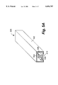
- FIG. 5A illustrates a cross-section view of a contact image sensor used in the present invention
- FIG. 5B illustrates a cross-section view of a back illumination source used in the present invention.
- FIG. 6 shows the internal functional diagram of a sensing module according to one embodiment of the present invention.
- FIG. 1 shows a schematic diagram embodying a portable scanner application.
- Scanner 100 is a sheet-fed scanner and connected, through communication cable 112, to computing device 102 which may be an IBM PC or PC-compatible desktop or laptop computer operating under a window operating system, for example, Windows 98 from Microsoft Corporation.
- computing device 102 may be an IBM PC or PC-compatible desktop or laptop computer operating under a window operating system, for example, Windows 98 from Microsoft Corporation.
- scanner 100 scans a sheet-like scanning object 110, such as a piece of paper or film with text and graphics thereon.
- the scanning result generally a digital image, is transferred to computing device 102 through communication cable 112.
- the image may then be manipulated for desired visual effects by a computer program in computing device 102.
- Computing device 102 is provided with a display monitor 104 on which the scanned image or manipulated image can be displayed to users.
- Computing device 102 is further provided with a floppy disk drive 114 with which removable floppy disk media may be read or written, fixed disk drive 116 for storing image files and application program files, a keyboard 106 for permitting input of text data, such as titles and names for scanned image files, and a pointing device 108 such as a mouse or the like which is also provided to permit execution of commands, for example, to display the scanned and manipulated images on display monitor 104.
- FIG. 2 shows a systemic diagram of a configuration in which the present invention may be practiced.
- Scanner 100 converts a scanning object 110 to a corresponding image 210.
- scanner 100 is capable of scanning both opaque and transparent materials.
- the opaque materials are referred to those scanning objects that a flatbed scanner can scan such as pictures or pages from a book or an article.
- the transparent materials are meant those such as negative/positive films, X-ray films, mylar films for overhead projectors or films for CAD and photography to name just a few.
- image 210 comprises a plurality of pixels, each pixel represented by a numerical value representing the intensity of the light reflectance falling on a sensor in scanner 100 from a corresponding dot in scanning object 110.
- the scanning object 110 is an 8.5 inch by 11 inch paper or film; the resultant image 210 has a size 850 by 1100 pixels and is in 8-bit format.
- each square inch of scanning object 110 is represented by 100 by 100 pixels. If all the pixels in the square inch are 255, the corresponding square inch in scanning object 110 is white. Conversely if all the pixels in the square inch are 0, the corresponding square inch in scanning object 110 is dark. It can be understood that any pixels having a value between 0 and 255, i.e. the gray scale, represent the variations of contents in scanning object 110.
- image 210 comprises three individual gray scale images, each generally representing one chromatic intensity image, such as red, green and blue intensity images.
- each dot in scanning object 110 is represented by a three-intensity-value vector, such as [23, 45, 129], hence image 210 comprising three intensity images.
- Scanner 100 comprises a sensing module 200, a memory 202, and a post signal-processing module 204.
- the operations and principles of memory 202 and post signal-processing module 204 are known to those skilled in the art. Further the present invention is preferably embodied in sensing module 200, therefore other hardware or processes in scanner 100 are not to be described in detail to avoid unnecessarily obscuring aspects of the present invention.
- FIG. 3 is a side view of a sheet-fed style portable scanner according to one embodiment of the present invention.
- casting or case 300 provides a compartment that houses a sensing module 302.
- casting 300 is made of a light but solid plastic material and provides enough space to house all components therein. It should be pointed out, however, that the packaging or shape of the scanner does not affect the operations of the present invention and is indeed an implementation preference. Those skilled in the art will appreciate that the present invention works more efficiently in those portable sheet-fed style scanners but can be applied equally well in other appropriate scanners.
- sensing module 200 consisting of an upper module 318 and a bottom module 320, comprises an illumination system comprising two illumination sources 304 and 306, an optical system 308, and an image sensor 310.
- Casing 300 is provided to integrate all the components in an enclosed compartment according to one embodiment of the present invention.
- the illumination system comprises a front illumination source 304 and a back illumination source 306.
- the combined front and back illumination sources 304 and 306 is one of the features in the present invention and the utilities thereof will be soon appreciated by those skilled in the art.
- front illumination source 304 in upper module 318 comprises light emitting diodes, preferably a red (LED), a green LED, and a blue LED, each can be independently and respectively turned on and off.
- Scanning object 316 may be a sheet of paper or film and rolled in by a motion mechanism through a gap between upper module 318 and bottom module 320. The gap, typically, one eighth of an inch, is formed to let scanning object 316 pass through an optical path 322.
- image sensor 310 is focused at optical path by optical lens 308, anything passing through optical path 322 will be imaged by image sensor 310 after a command to start the scanning operation is executed.
- One of the important distinctions from other scanners that may scan both opaque and transparent materials is that the scanning object, regardless opaque or transparent, is provided at the same scanning path.
- the motion mechanism causes scanning object 316 to move from one end to another end, passing optical path 322, so that image sensor 310 can image or scan the scanning object 316.
- the motion mechanism comprises a motor and a roller.
- the motor preferably a step motor, works in synchronization with image sensor 310 and the roller having a rubber-like surface is driven by the motor. Scanning object 316 is thus carried by the roller and moved through image sensor 310 from one opening to another opening of casting 300.
- front illumination source 304 is for opaque scanning materials while back illumination source 306 is for transparent scanning object.
- front illumination source 304 is turned on and (opaque) scanning object 316 is passed through the image sensor 310, the entire front face of scanning object 316 is successively illuminated and hence imaged.
- front illumination source 304 turns on alternatively each of the color lights therein, so the image sensor 310 can produce corresponding intensity images. For example, when a red light in front illumination source 304 is turned on, one line of scanning object 316 is imaged by image sensor 310. The same line of scanning object 316 is imaged when a green light and a blue light in front illumination source 304 are respectively turned on.
- FIGS. 4A and 4B demonstrate respectively the front illumination for an opaque scanning object and the back illumination for a transparent scanning object.
- scanning object 316 is an opaque scanning material, such as a page, having a front surface facing to image sensor 400.
- Illumination source 404 illuminates the front surface, light reflected from the surface is collected by optical lens 404 and focused upon image sensor 400 so that an image of the surface is obtained.
- scanning object 316 is a transparent scanning material, such as a film.
- Illumination source 404 provides illumination from the back of transparent scanning object 316 such that light through transparent scanning object 316, namely transmitted light, is collected by optical lens 404 and focused upon image sensor 400 so that an image of the transparent scanning object is obtained.
- Illumination 404 in FIG. 4A and FIG. 4B corresponds respectively to front illumination source 304 and back illumination source 306.
- back illumination source 306 is turned on when (transparent) scanning object 316 is present between upper module 302 and bottom module 320.
- Back illumination source 306 is preferably a white light source.
- back illumination source 306 is an elongated light guide having a length comparable to a width of scanning object 316 so that every scanning line of scanning object 316 can be evenly illuminated.
- the light guide may be made from a fluorescent light source or three distinct color light source as described more below. It should be pointed out that the characteristics of the front and back illumination sources do not directly affect the operations of the present invention.
- One of the key features of the present invention is that the front and back illumination sources work conversely, namely only one is turned on when a scanning object is present therein. In other words, one is turned off when the other one is turned on.
- a pair of light source (emitter) 330 and photodetector 332 is used to detect if scanning object 316 is opaque or transparent.
- light source 330 and photodetector 332 are aligned so that photodetector 332 is always activated by light source 330.
- photodetector 332 becomes inactivated because of the blocked light source 330 by the opaque sheet.
- a control circuit not shown in the figure and understood to those skilled in the art, can automatically turn on front illumination source 304.
- photodetector 332 remains activated because light source 330 can go through the transparent sheet. Therefore the same control circuit can automatically turn on back illumination source 306.
- the control circuit can instruct the control circuit to turn on the appropriate illumination source for the right scanning object.
- One of the ways is simply based on a manual determination.
- the front illumination source is a default selected illumination source for all scanning objects.
- the button can be pressed to activate the back illumination source and meanwhile turn off the front illumination so that a proper illumination light source is always provided.
- upper module 318 is a contact image sensor.
- the contact image sensor is an elongated tubular casting integrating the image sensor and the optical lens therein.
- the contact image sensor may include the front illumination source.
- FIG. 5A there is shown a cross-section view of an exemplary contact image sensor 500 that may correspond to upper module 318 of FIG. 3.
- Contact image sensor 500 comprises an image sensor 504, an optical lens system 506 and a front illumination source 508, all integrated in a tubular casting 502.
- Tubular casting 502 or contact image sensor 500 may be extended to accommodate the maximum width of a scanning object. For example, a scanner is designed to scan a sheet size of 8.5 by 11 inches, therefore contact image sensor 500 may have a length of 9 inches to account for the margins.
- Image sensor 504 is typically a linear sensor having a density of 300 photodetectors per inch.
- Optical lens (system) 506 is generally an array of one-to-one erect graded index micro (cylindrical or rod) lens and front illumination source 508 comprises fundamental three color lights, such as red, green and blue LED. It should be understood that the present invention is independent of the characteristics of the optical lens and the lights in contact image sensor 500.
- the cylindrical lens and LED-based front illumination source used herein is just to show one example using the present invention.
- contact image sensor 500 is a CIS 100, obtained from ScanVision, Incorporated having a business of 1346 Ridder Park Drive, San Jose, Calif. 95131, USA.
- FIG. 5B illustrates a cross-section view of a back illumination module 550 that may correspond to bottom module of FIG. 3.
- Back illumination module 550 ideally has the same length as the upper module 318 of FIG. 3 or contact image sensor 500 of FIG. 5A.
- back illumination module 550 provides a modular back illumination source that includes a light source 552 therein.
- Light source 552 can be a fluorescent light source or three different color light sources, typically a red LED, a green LED and a blue LED. When light source 552 is a fluorescent light source, it can be appreciated that the resultant image of a transparent scanning object will be a gray-level image.
- upper surface 554 is preferably a diffused material (sheet) so that lighting from light source 556 through diffusing sheet 554 is evenly distributed.
- front illumination source 508 of FIG. 5A and light source 556 in back illumination module 550 work conversely, namely only one of the illumination sources is on at one time depending on weather the scanning object is opaque or transparent.
- FIG. 6 shows the internal functional diagram of sensing module 300 according to one embodiment of the present invention.
- first one 602 is for back illumination and second one 604, 606 and 608 are for front illumination.
- Back illumination source 602 may be a LED or a light guide or tubular light source of FIG. 5B, controlled by an "ON" signal at connector 603.
- the front illumination source comprises a red LED 604, a green LED 606 and a blue LED 608, each controlled respectively by an "ON" signal at respective connectors 402, 404, and 406.
- either illumination source 602 is turned “ON” for a transparent scanning object or the LEDs are successively turned “ON” for an opaque scanning object.
- the rod lens array 610 collects either the reflected light from the opaque scanning object illuminated by one of red LED 604, green LED 606 and blue LED 608 or transmitted light from the transparent scanning object illuminated by back illumination source 602 and focuses the light onto image sensor 612.
- Image sensor 612 comprises, for example, N photodetectors. Each of the photodetectors collects light cast thereon during each integration process and generates a pixel signal. Upon the completion of the integration process, the pixel signals, each respectively generated by one of the photodetectors, are sequentially readout to the video bus 614 as a scanning signal via readout switch array 616. It should be noted that image sensor 612 is assumed a CMOS type sensor and those skilled in the art will understand that the description works the same for CCD type sensors.
- Switch array 616 comprises the same number of the readout switches as the number of the photodetectors in the image array 120. It is understood to those skilled in the art that each of the readout switches may be implemented by a diode that becomes “On” or “passing through” when a proper voltage is applied across. As shown in the figure, the scanning signal is coupled to a gain & offset control circuit 618. The scanning signal is processed, including amplified and offset, in gain & offset control circuit 618 with respect to a desired adjustment and subsequently output as a video signal at V out .
Abstract
Description
Claims (20)
Priority Applications (1)
| Application Number | Priority Date | Filing Date | Title |
|---|---|---|---|
| US09/127,237 US6054707A (en) | 1998-07-31 | 1998-07-31 | Portable scanners capable of scanning both opaque and transparent materials |
Applications Claiming Priority (1)
| Application Number | Priority Date | Filing Date | Title |
|---|---|---|---|
| US09/127,237 US6054707A (en) | 1998-07-31 | 1998-07-31 | Portable scanners capable of scanning both opaque and transparent materials |
Publications (1)
| Publication Number | Publication Date |
|---|---|
| US6054707A true US6054707A (en) | 2000-04-25 |
Family
ID=22429035
Family Applications (1)
| Application Number | Title | Priority Date | Filing Date |
|---|---|---|---|
| US09/127,237 Expired - Lifetime US6054707A (en) | 1998-07-31 | 1998-07-31 | Portable scanners capable of scanning both opaque and transparent materials |
Country Status (1)
| Country | Link |
|---|---|
| US (1) | US6054707A (en) |
Cited By (20)
| Publication number | Priority date | Publication date | Assignee | Title |
|---|---|---|---|---|
| US6275309B1 (en) * | 1998-09-16 | 2001-08-14 | Syscan, Inc. | Lightweight mobile scanners |
| US6376822B1 (en) * | 1997-08-12 | 2002-04-23 | Rohm Co., Ltd. | Image reading apparatus |
| US20020101626A1 (en) * | 2001-02-01 | 2002-08-01 | Pandipati Radha K. C. | Bills scanner and financial organizer |
| US20020100863A1 (en) * | 2001-01-30 | 2002-08-01 | Spears Kurt E. | Optical image scanner with color and intensity compensation during lamp warmup |
| US20020131636A1 (en) * | 2001-03-19 | 2002-09-19 | Darwin Hou | Palm office assistants |
| US20020154342A1 (en) * | 2001-04-20 | 2002-10-24 | Haining David S. | Portable photo scanner with task assigner |
| US6538243B1 (en) * | 2000-01-04 | 2003-03-25 | Hewlett-Packard Company | Contact image sensor with light guide having least reflectivity near a light source |
| US20040012825A1 (en) * | 2002-07-22 | 2004-01-22 | Eastman Kodak Company | Method and apparatus for transparency scanning with a duplex reflective scanner |
| US20040083134A1 (en) * | 2002-10-21 | 2004-04-29 | Raphael Spero | System and method for capture, storage and processing of receipts and related data |
| US20040119417A1 (en) * | 2002-12-20 | 2004-06-24 | Hsiu-O Hsu | Scanner with common illumination light source |
| US20040130756A1 (en) * | 2003-01-06 | 2004-07-08 | Chun-Jen Chen | Method for selecting and adjusting scanner illuminant |
| US20060012103A1 (en) * | 2004-07-13 | 2006-01-19 | Lite-On Technology Corporation | Media feeding device with scanning and fixing functions for transparent documents |
| US20070040031A1 (en) * | 2001-11-27 | 2007-02-22 | Transpacific Ip, Ltd. | Dual light source voltage-modulated reciprocal control circuit for scanner |
| US20070262145A1 (en) * | 2005-12-09 | 2007-11-15 | Larue John D | Round surface scanner |
| US20100056049A1 (en) * | 2008-09-04 | 2010-03-04 | Darwin Hu | Wireless Mobile Telescanners |
| US9591212B1 (en) * | 2015-10-30 | 2017-03-07 | Essential Products, Inc. | System and method for reducing the number of ports associated with a mobile device |
| US9762712B2 (en) | 2015-10-30 | 2017-09-12 | Essential Products, Inc. | System and method for reducing the number of ports associated with a mobile device |
| US9916606B2 (en) | 2011-04-18 | 2018-03-13 | Castle Bookkeeping Wizard Pty Ltd | System and method for processing a transaction document including one or more financial transaction entries |
| US10453151B2 (en) | 2001-02-01 | 2019-10-22 | Kris Engineering, Inc. | Receipts scanner and financial organizer |
| US10482521B2 (en) | 2013-01-18 | 2019-11-19 | [24]7.ai, Inc. | Intent prediction based recommendation system using data combined from multiple channels |
Citations (4)
| Publication number | Priority date | Publication date | Assignee | Title |
|---|---|---|---|---|
| US5705805A (en) * | 1995-02-21 | 1998-01-06 | Microtek International, Inc. | Transmissive/reflective optical scanning apparatus |
| US5764493A (en) * | 1995-12-11 | 1998-06-09 | Liao; Chun-Chi | Palm top image scanner back lighting device |
| US5780829A (en) * | 1997-01-31 | 1998-07-14 | Mustek Systems Inc. | Flat-plate scanner having a beam-splitting prism/mirror and two light emitting sources |
| US5895914A (en) * | 1997-02-25 | 1999-04-20 | Musktek Systems Inc. | Scanner capable of scanning penetrative document and reflective document with single lamp |
-
1998
- 1998-07-31 US US09/127,237 patent/US6054707A/en not_active Expired - Lifetime
Patent Citations (4)
| Publication number | Priority date | Publication date | Assignee | Title |
|---|---|---|---|---|
| US5705805A (en) * | 1995-02-21 | 1998-01-06 | Microtek International, Inc. | Transmissive/reflective optical scanning apparatus |
| US5764493A (en) * | 1995-12-11 | 1998-06-09 | Liao; Chun-Chi | Palm top image scanner back lighting device |
| US5780829A (en) * | 1997-01-31 | 1998-07-14 | Mustek Systems Inc. | Flat-plate scanner having a beam-splitting prism/mirror and two light emitting sources |
| US5895914A (en) * | 1997-02-25 | 1999-04-20 | Musktek Systems Inc. | Scanner capable of scanning penetrative document and reflective document with single lamp |
Cited By (41)
| Publication number | Priority date | Publication date | Assignee | Title |
|---|---|---|---|---|
| US6376822B1 (en) * | 1997-08-12 | 2002-04-23 | Rohm Co., Ltd. | Image reading apparatus |
| US6275309B1 (en) * | 1998-09-16 | 2001-08-14 | Syscan, Inc. | Lightweight mobile scanners |
| US6704124B2 (en) * | 1998-09-16 | 2004-03-09 | Syscan (Shenzhen) Technology Co., Limited | Mobile scanners |
| US6538243B1 (en) * | 2000-01-04 | 2003-03-25 | Hewlett-Packard Company | Contact image sensor with light guide having least reflectivity near a light source |
| US20020100863A1 (en) * | 2001-01-30 | 2002-08-01 | Spears Kurt E. | Optical image scanner with color and intensity compensation during lamp warmup |
| US8373912B2 (en) | 2001-02-01 | 2013-02-12 | Kris Engineering, Inc. | Receipts scanner and financial organizer |
| US8203765B2 (en) | 2001-02-01 | 2012-06-19 | Kris Engineering, Inc. | Receipts scanner and financial organizer |
| US20020101626A1 (en) * | 2001-02-01 | 2002-08-01 | Pandipati Radha K. C. | Bills scanner and financial organizer |
| US11004158B2 (en) | 2001-02-01 | 2021-05-11 | Kris Engineering, Inc. | Receipts scanner and financial organizer |
| US7746510B2 (en) | 2001-02-01 | 2010-06-29 | Pandipati Radha K C | Receipts scanner and financial organizer |
| US10453151B2 (en) | 2001-02-01 | 2019-10-22 | Kris Engineering, Inc. | Receipts scanner and financial organizer |
| US10049410B2 (en) | 2001-02-01 | 2018-08-14 | Kris Engineering, Inc. | Receipts scanner and financial organizer |
| US9165391B2 (en) | 2001-02-01 | 2015-10-20 | Kris Engineering, Inc. | Receipts scanner and financial organizer |
| US20100228659A1 (en) * | 2001-02-01 | 2010-09-09 | Pandipati Radha K C | Receipts scanner and financial organizer |
| US8693070B2 (en) | 2001-02-01 | 2014-04-08 | Kris Engineering, Inc. | Receipts scanner and financial organizer |
| US8009334B2 (en) | 2001-02-01 | 2011-08-30 | Kris Engineering, Inc. | Receipts scanner and financial organizer |
| US20020131636A1 (en) * | 2001-03-19 | 2002-09-19 | Darwin Hou | Palm office assistants |
| US6891979B2 (en) * | 2001-03-19 | 2005-05-10 | Syscan, Inc. | Pocket scanners |
| US20020131637A1 (en) * | 2001-03-19 | 2002-09-19 | Darwin Hu | Pocket scanners |
| US7595914B2 (en) * | 2001-04-20 | 2009-09-29 | Hewlett Packard Development Company, L.P. | Portable photo scanner with task assigner |
| US20020154342A1 (en) * | 2001-04-20 | 2002-10-24 | Haining David S. | Portable photo scanner with task assigner |
| US7581679B2 (en) * | 2001-11-27 | 2009-09-01 | Chin-Lin Chang | Dual light source voltage-modulated reciprocal control circuit for scanner |
| US20070040031A1 (en) * | 2001-11-27 | 2007-02-22 | Transpacific Ip, Ltd. | Dual light source voltage-modulated reciprocal control circuit for scanner |
| US20040012825A1 (en) * | 2002-07-22 | 2004-01-22 | Eastman Kodak Company | Method and apparatus for transparency scanning with a duplex reflective scanner |
| US7142335B2 (en) | 2002-07-22 | 2006-11-28 | Eastman Kodak Company | Method and apparatus for transparency scanning with a duplex reflective scanner |
| US20040083134A1 (en) * | 2002-10-21 | 2004-04-29 | Raphael Spero | System and method for capture, storage and processing of receipts and related data |
| US7069240B2 (en) | 2002-10-21 | 2006-06-27 | Raphael Spero | System and method for capture, storage and processing of receipts and related data |
| USRE47309E1 (en) | 2002-10-21 | 2019-03-19 | The Neat Company, Inc. | System and method for capture, storage and processing of receipts and related data |
| US20040119417A1 (en) * | 2002-12-20 | 2004-06-24 | Hsiu-O Hsu | Scanner with common illumination light source |
| US7679791B2 (en) * | 2003-01-06 | 2010-03-16 | Chun-Jen Chen | Method for selecting and adjusting scanner illuminant |
| US20040130756A1 (en) * | 2003-01-06 | 2004-07-08 | Chun-Jen Chen | Method for selecting and adjusting scanner illuminant |
| US7505183B2 (en) * | 2004-07-13 | 2009-03-17 | Lite-On Technology Corporation | Media feeding device with scanning and fixing functions for transparent documents |
| US20060012103A1 (en) * | 2004-07-13 | 2006-01-19 | Lite-On Technology Corporation | Media feeding device with scanning and fixing functions for transparent documents |
| US20070262145A1 (en) * | 2005-12-09 | 2007-11-15 | Larue John D | Round surface scanner |
| US7780085B2 (en) | 2005-12-09 | 2010-08-24 | Larue John D | Round surface scanner |
| US20100056049A1 (en) * | 2008-09-04 | 2010-03-04 | Darwin Hu | Wireless Mobile Telescanners |
| US9916606B2 (en) | 2011-04-18 | 2018-03-13 | Castle Bookkeeping Wizard Pty Ltd | System and method for processing a transaction document including one or more financial transaction entries |
| US10482521B2 (en) | 2013-01-18 | 2019-11-19 | [24]7.ai, Inc. | Intent prediction based recommendation system using data combined from multiple channels |
| US9785820B2 (en) | 2015-10-30 | 2017-10-10 | Essential Products, Inc. | System and method for reducing the number of ports associated with a mobile device |
| US9762712B2 (en) | 2015-10-30 | 2017-09-12 | Essential Products, Inc. | System and method for reducing the number of ports associated with a mobile device |
| US9591212B1 (en) * | 2015-10-30 | 2017-03-07 | Essential Products, Inc. | System and method for reducing the number of ports associated with a mobile device |
Similar Documents
| Publication | Publication Date | Title |
|---|---|---|
| US6054707A (en) | Portable scanners capable of scanning both opaque and transparent materials | |
| US6891979B2 (en) | Pocket scanners | |
| US6704124B2 (en) | Mobile scanners | |
| US6459506B1 (en) | Lightweight dual-mode mobile scanner powered from a universal serial bus port | |
| US6271939B1 (en) | Transparent and flatbed scanner | |
| US6054703A (en) | Sensing module for accelerating signal readout from image sensors | |
| US6104510A (en) | Hybrid illumination system for accelerating light integration in image sensing systems | |
| US5923042A (en) | Method and apparatus for optically scanning transparent media | |
| US6323933B1 (en) | Image reading device and method | |
| US5900950A (en) | Image scanner with a function of initiating scanning automatically | |
| JP2000013568A (en) | Scanner device | |
| KR100226014B1 (en) | Information reading device | |
| US20020113196A1 (en) | Method and apparatus for scanning colors using multiple arrays of photodetectors | |
| US20050052713A1 (en) | Scanning method and system | |
| TW563332B (en) | Space-saving flatbed scanner | |
| US9232088B1 (en) | Scanning in a defined region on a display screen | |
| JPH10154221A (en) | Method for reading image and its device, and input/ output-unified information operating device | |
| US6252663B1 (en) | Scanning and printing systems with color discrimination | |
| US6522428B1 (en) | Structure of foldable optical path | |
| US6211508B1 (en) | Lensless optical system in imaging sensing module | |
| US5926290A (en) | Document-tray-driven apparatus for a photo drive | |
| JP2877842B2 (en) | Image reading device and image reading system | |
| US20020113193A1 (en) | Motion synchronized two-dimensional linear image sensor array | |
| JP2000196831A (en) | Improved flat-bed scanner | |
| JP2004215095A (en) | Step shadow erasing apparatus for cut-and-paste original for scanner |
Legal Events
| Date | Code | Title | Description |
|---|---|---|---|
| AS | Assignment |
Owner name: SCANVISION INCORPORATED, CALIFORNIA Free format text: ASSIGNMENT OF ASSIGNORS INTEREST;ASSIGNOR:HOU, ALPHA;REEL/FRAME:009364/0810 Effective date: 19980731 |
|
| FPAY | Fee payment |
Year of fee payment: 4 |
|
| REMI | Maintenance fee reminder mailed | ||
| FEPP | Fee payment procedure |
Free format text: PETITION RELATED TO MAINTENANCE FEES GRANTED (ORIGINAL EVENT CODE: PMFG); ENTITY STATUS OF PATENT OWNER: SMALL ENTITY Free format text: PETITION RELATED TO MAINTENANCE FEES FILED (ORIGINAL EVENT CODE: PMFP); ENTITY STATUS OF PATENT OWNER: SMALL ENTITY |
|
| REIN | Reinstatement after maintenance fee payment confirmed | ||
| FP | Lapsed due to failure to pay maintenance fee |
Effective date: 20080425 |
|
| PRDP | Patent reinstated due to the acceptance of a late maintenance fee |
Effective date: 20080919 |
|
| FPAY | Fee payment |
Year of fee payment: 8 |
|
| STCF | Information on status: patent grant |
Free format text: PATENTED CASE |
|
| SULP | Surcharge for late payment | ||
| AS | Assignment |
Owner name: SYSCAN, INC., CALIFORNIA Free format text: CHANGE OF NAME;ASSIGNOR:SCANVISION INCORPORATED;REEL/FRAME:021691/0885 Effective date: 19990607 |
|
| AS | Assignment |
Owner name: BANKENGINE TECHNOLOGIES INC., CANADA Free format text: ACQUISITION OF SYSCAN, INC. BY BANKENGINE TECHNOLOGIES INC.;ASSIGNOR:SYSCAN, INC.;REEL/FRAME:021861/0765 Effective date: 20040329 |
|
| AS | Assignment |
Owner name: SYSCAN IMAGING, INC., CALIFORNIA Free format text: CHANGE OF NAME;ASSIGNOR:BANKENGINE TECHNOLOGIES INC.;REEL/FRAME:021890/0358 Effective date: 20040402 |
|
| AS | Assignment |
Owner name: SYSVIEW TECHNOLOGY, INC., CALIFORNIA Free format text: CHANGE OF NAME;ASSIGNOR:SYSCAN IMAGING, INC.;REEL/FRAME:021890/0959 Effective date: 20060627 |
|
| AS | Assignment |
Owner name: DOCUMENT CAPTURE TECHNOLOGIES, INC., CALIFORNIA Free format text: MERGER;ASSIGNOR:SYSVIEW TECHNOLOGY, INC.;REEL/FRAME:021901/0213 Effective date: 20071226 |
|
| FPAY | Fee payment |
Year of fee payment: 12 |
|
| AS | Assignment |
Owner name: AMBIR TECHNOLOGY, INC., ILLINOIS Free format text: ASSIGNMENT OF ASSIGNORS INTEREST;ASSIGNOR:DOCUMENT CAPTURE TECHNOLOGIES, INC.;REEL/FRAME:036487/0786 Effective date: 20150902 |