US6057632A - Frequency and bandwidth controlled ultrasound transducer - Google Patents
Frequency and bandwidth controlled ultrasound transducer Download PDFInfo
- Publication number
- US6057632A US6057632A US09/094,414 US9441498A US6057632A US 6057632 A US6057632 A US 6057632A US 9441498 A US9441498 A US 9441498A US 6057632 A US6057632 A US 6057632A
- Authority
- US
- United States
- Prior art keywords
- transducer
- elevation
- transducer element
- thickness
- matching layer
- Prior art date
- Legal status (The legal status is an assumption and is not a legal conclusion. Google has not performed a legal analysis and makes no representation as to the accuracy of the status listed.)
- Expired - Lifetime
Links
- 238000002604 ultrasonography Methods 0.000 title claims abstract description 29
- 230000001419 dependent effect Effects 0.000 claims abstract description 11
- 239000000919 ceramic Substances 0.000 description 14
- 238000003384 imaging method Methods 0.000 description 14
- 238000003491 array Methods 0.000 description 12
- 230000005284 excitation Effects 0.000 description 9
- 239000000463 material Substances 0.000 description 5
- RYGMFSIKBFXOCR-UHFFFAOYSA-N Copper Chemical compound [Cu] RYGMFSIKBFXOCR-UHFFFAOYSA-N 0.000 description 3
- 229910052802 copper Inorganic materials 0.000 description 3
- 239000010949 copper Substances 0.000 description 3
- 230000035515 penetration Effects 0.000 description 3
- VILCJCGEZXAXTO-UHFFFAOYSA-N 2,2,2-tetramine Chemical compound NCCNCCNCCN VILCJCGEZXAXTO-UHFFFAOYSA-N 0.000 description 2
- 238000005452 bending Methods 0.000 description 2
- 238000010586 diagram Methods 0.000 description 2
- 238000004519 manufacturing process Methods 0.000 description 2
- 238000000034 method Methods 0.000 description 2
- 239000002245 particle Substances 0.000 description 2
- 230000000737 periodic effect Effects 0.000 description 2
- 238000001228 spectrum Methods 0.000 description 2
- 239000004642 Polyimide Substances 0.000 description 1
- PNEYBMLMFCGWSK-UHFFFAOYSA-N aluminium oxide Inorganic materials [O-2].[O-2].[O-2].[Al+3].[Al+3] PNEYBMLMFCGWSK-UHFFFAOYSA-N 0.000 description 1
- 238000004458 analytical method Methods 0.000 description 1
- 230000002902 bimodal effect Effects 0.000 description 1
- 238000006243 chemical reaction Methods 0.000 description 1
- 238000013329 compounding Methods 0.000 description 1
- 150000001875 compounds Chemical class 0.000 description 1
- 230000007423 decrease Effects 0.000 description 1
- 230000003247 decreasing effect Effects 0.000 description 1
- 238000006073 displacement reaction Methods 0.000 description 1
- PCHJSUWPFVWCPO-UHFFFAOYSA-N gold Chemical compound [Au] PCHJSUWPFVWCPO-UHFFFAOYSA-N 0.000 description 1
- 229910052737 gold Inorganic materials 0.000 description 1
- 239000010931 gold Substances 0.000 description 1
- 238000012886 linear function Methods 0.000 description 1
- 229920001721 polyimide Polymers 0.000 description 1
- 229920001296 polysiloxane Polymers 0.000 description 1
- 229920002635 polyurethane Polymers 0.000 description 1
- 239000004814 polyurethane Substances 0.000 description 1
- 230000009467 reduction Effects 0.000 description 1
- 229920002631 room-temperature vulcanizate silicone Polymers 0.000 description 1
- 230000035945 sensitivity Effects 0.000 description 1
Images


Classifications
-
- B—PERFORMING OPERATIONS; TRANSPORTING
- B06—GENERATING OR TRANSMITTING MECHANICAL VIBRATIONS IN GENERAL
- B06B—METHODS OR APPARATUS FOR GENERATING OR TRANSMITTING MECHANICAL VIBRATIONS OF INFRASONIC, SONIC, OR ULTRASONIC FREQUENCY, e.g. FOR PERFORMING MECHANICAL WORK IN GENERAL
- B06B1/00—Methods or apparatus for generating mechanical vibrations of infrasonic, sonic, or ultrasonic frequency
- B06B1/02—Methods or apparatus for generating mechanical vibrations of infrasonic, sonic, or ultrasonic frequency making use of electrical energy
- B06B1/06—Methods or apparatus for generating mechanical vibrations of infrasonic, sonic, or ultrasonic frequency making use of electrical energy operating with piezoelectric effect or with electrostriction
- B06B1/0607—Methods or apparatus for generating mechanical vibrations of infrasonic, sonic, or ultrasonic frequency making use of electrical energy operating with piezoelectric effect or with electrostriction using multiple elements
- B06B1/0622—Methods or apparatus for generating mechanical vibrations of infrasonic, sonic, or ultrasonic frequency making use of electrical energy operating with piezoelectric effect or with electrostriction using multiple elements on one surface
Definitions
- This invention relates to broadband transducers particularly for use in the medical ultrasound imaging field that provide frequency and bandwidth control of elevation aperture size and position as well as elevation focal depth of an emitted ultrasound beam through a combination of variations in thickness of each transducer element, variations in spacing between adjacent transducer elements and/or variations in radii of curvature of each transducer element.
- Acoustic imaging systems incorporate acoustic transducers for converting electrical signals into mechanical pressure or particle displacement signals and vice versa.
- the conversion is done typically by a piezoelectric ceramic, or in the case of transducer arrays by an array of ceramics.
- the plane defined by the axis of the array and the normal to the array's active surface is known as the azimuthal plane and the plane orthogonal to the azimuthal plane is known as the elevation plane.
- steering, focusing and aperture control are accomplished electronically by the imaging system through applying appropriate delay, phase and apodization to the individual array elements.
- An example of an acoustic imaging system can be found in U.S. Pat. No. 4,550,607 (Maslak et al.), for example.
- elevation plane focusing can generally be categorized as either lens focused or mechanically focused.
- lens focused arrays the active emitting surface of the array is flat in the elevation plane and a shaped lens is placed between the object to be imaged and the active surface of the array.
- U.S. Pat. Nos. 4,686,408 and 5,163,436 describe lens focused phased array transducers.
- the material used to form the lens is typically silicone based and, unfortunately, also has the undesirable property of absorbing or attenuating passing ultrasound energy and thereby reducing the overall sensitivity of the transducer array.
- Mechanically focused transducer arrays involve curving the active surface of the transducer array along the elevation direction. The elevation aperture size and elevation focus depth for lens and mechanically focused transducer arrays, however, remains fixed.
- 1.5 and 2-D arrays require, respectively, 2 to 4 times and 16 to 64 times more number of acquisition channels compared to one dimensional arrays. Therefore a much more complex and expensive system hardware is required. They, however, offer better control over elevation beam width (slice thickness) which potentially improves detectability of targets that have a small extent in elevation.
- 2-D arrays also allow three-dimensional imaging.
- Some of the basic design parameters considered when designing a transducer array include the center frequency, bandwidth, elevation aperture size, elevation focal depth and element spacing.
- Center frequency and bandwidth define the pass-band of the transducer impulse response.
- the frequency of operation, together with the aperture size, determine the lateral resolution of the beam both in azimuth and elevation, and the beam's penetration. Therefore, for imaging shallow structures where penetration is not an issue, the operating frequency should be high to maximize detail resolution. However, to image deep, the operating frequency has to be low in order to penetrate.
- the absolute bandwidth for any given operating frequency determines the axial resolution at focus. For a given operating frequency, elevation aperture size and elevation focal depth determine the focusing in elevation.
- the elevation aperture should be small and focusing depth should be shallow to maximize contrast resolution in the near field.
- elevation aperture should be large and focusing depth should be deep for the best resolution and signal-to-noise ratio.
- Element spacing along with the operating frequency, determines the grating lobe levels and also, given the number of transducer elements, determines the physical aperture size. Therefore, for high operating frequencies where grating lobe levels may be an issue, element spacing has to be small to minimize the grating lobe levels. But for low operating frequencies where grating lobe levels are not an issue, element spacing should be large to maximize the aperture size and thus resolution and penetration.
- U.S. Pat. Nos. 5,415,175 (“the '175 patent”) and 5,438,998 (“the '998 patent”) describe varying the thickness of a transducer ceramic and matching layers in elevation such that the ceramic is thick at the edges and narrow at the center.
- the elevation aperture becomes a function of frequency and bandwidth; tapered and small at high frequencies and untapered and wide at low frequencies, and the elevation focal depth is determined by the ceramic's thickness profile and the applied bending.
- This technique works well to achieve a narrow elevation aperture if the frequency is high and the bandwidth is narrow.
- the elevation apodization may become inverse-cosine like. This may cause increased elevation side lobe levels for low frequency, narrow bandwidth operations.
- the '412 application also suggests bending the array along the elevation direction. This allows, if the elements are convex, steering the elevation beam by changing the operating frequency or, if the elements are concave, focusing at a fixed focus at all frequencies.
- the ceramic and matching layer thickness can be optimized for each frequency.
- a wide bandwidth ultrasound transducer comprising: a plurality of transducer elements sequentially arranged in an azimuth direction wherein each transducer element is spaced from adjacent transducer elements in the azimuth direction; each transducer element extends from a first end to a second end in an elevation direction; each transducer element having a thickness in a range direction that increases from the first end to the second end wherein each transducer element is thinnest at the first end and thickest at the second end; and the spacing of the transducer elements increases from the first end to the second end so that the spacing is at a minimum at the first end and a maximum at the second end.
- a wide bandwidth ultrasound transducer comprising: a plurality of transducer elements sequentially arranged in an azimuth direction; each transducer element extends from a first end to a second end in an elevation direction; each transducer element having a thickness in a range direction that increases from the first end to the second end wherein each transducer element is thinnest at the first end and thickest at the second end; and each transducer element has a front surface defined by a concave surface having a concavity dependent on its position along the elevation direction wherein subsegments of an elevation aperture focus at shallower depths at the first end and deeper depths at the second end when the transducer is in use.
- FIG. 1 is a block diagram of an ultrasound system for generating an image.
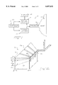
- FIG. 2 is a perspective view of a broadband transducer array according to a preferred embodiment of the present invention.
- FIG. 3 is a graph of the thickness profiles of the transducer element and matching layers as well as the curvature of a front acoustic matching layer.
- FIG. 4 is a graph of an assemble transducer element on a backing block.
- FIG. 5 is a perspective view of a broadband transducer array according to another preferred embodiment of the present invention.
- FIG. 6 is a cross-sectional view of the transducer array shown in FIG. 5 taken along lines 6--6.
- FIG. 7 is a top view of the transducer array shown in FIG. 2.
- FIG. 8 is a perspective view of a broadband transducer array according to another preferred embodiment in which the plurality of transducer elements have a front surface which is convex in shape.
- FIG. 1 is a block diagram of an ultrasound system 10 for generating an image of an object or body 12 being observed.
- the ultrasound system 10 has transmit circuitry 14 for transmitting electrical signals to an ultrasound transducer 16, receive circuitry 18 for processing the signals received by the transducer 16, and a display 20 for providing the image of the object 12 being observed in a region of examination.
- the transducer 16 converts electrical excitation signals provided by the transmit circuitry 14 to pressure waves and converts pressure waves reflected from the object 12 being examined into corresponding electrical signals which are then processed in the receive circuitry 18 and ultimately displayed. on display 20.
- the transmit circuitry 14 includes a transmit beamformer controlled by a controller 22 which applies analog transmit voltage waveforms via a multichannel switch (not shown) to an array of transducer elements housed in the transducer 16.
- the receive beamformer preferably includes a dynamic receive focusing system that allows the focus of the receive beamformer to be changed at a high rate in order to follow as accurately as possible the range along the ultrasonic scan line corresponding to the currently arriving signals.
- the transducer 16 will be described in greater detail with reference to FIGS. 2-4.
- FIG. 1 is meant to represent generically an ultrasound system and not to limit the present invention in any way.
- FIG. 2 is a perspective view of a broadband transducer array according to a preferred embodiment of the present invention. To simplify and illustrate the relevant features of the transducer not all of the components forming the transducer have been shown.
- the transducer 16 contains an array 24 of transducer elements 26 sequentially arranged along the x-azimuth direction.
- the indicated x, y and z directions are referred to as the x-azimuth, y-elevation and z-range directions, respectively.
- the array may, however, consist of any number of transducer elements each arranged in any desired geometrical configuration.
- the transducer elements 26 are disposed on a support or backing block 28.
- the backing block 28 is preferably made of a highly attenuative material such that ultrasound energy radiated in its direction (i.e., away from an object in a region of examination) is substantially absorbed.
- two acoustic matching layers 30 and 31 may be disposed on an active surface 27 of each transducer element 26.
- the active surface 27 of each transducer element refers to that surface that will face a region of examination when the transducer is in use and is opposite of a bottom surface that faces the backing block 28.
- each transducer element 26 has an electrode (not shown) formed on its top, active surface and its bottom surface.
- a flex circuit (not shown) is preferably disposed between each transducer element 26 and the backing block 28.
- the flex circuit (not shown) has a center pad area that is disposed directly beneath the bottom electrode of each transducer element. Traces (not shown) extend from both sides of the center pad area, and, when the transducer is in use, the traces are coupled to the transmit and receive circuits shown in FIG. 1.
- the flex circuit preferably delivers an excitation signal from the transmit circuitry to the transducer elements 26 either all at one time or sequentially as is well known to those of ordinary skill in the art.
- a ground flex circuit (not shown) is preferably disposed on the top electrode of each transducer element between the transducer element 26 and the acoustic matching layer 30.
- the flex circuits may be, for example, any interconnecting design used in the acoustic or integrated circuit fields.
- the flexible circuits are typically made of a copper layer carrying a lead for exciting the transducer element.
- the copper layer may be bonded to a piece of polyimide material, typically KAPTONTM.
- the center pad area of the copper layer is coextensive in size with the electrodes formed on each transducer element.
- the interconnect circuit may be gold plated to improve its contact performance.
- Such a flexible circuit is manufactured by Sheldahl of Northfield, Minn.
- each transducer element 26 Preferably two acoustic matching layers 30 and 31 are disposed on each transducer element 26.
- the matching layer 30 disposed closest to the transducer element 26 is preferably a high impedance matching layer and the matching layer 31 disposed farthest from the transducer element 26 is a low impedance matching layer.
- the low impedance matching layer is made of Dow Corning's DER 332 and DEH 24 having a longitudinal velocity of 2630 m/s and a density of 1200 kg/m 3
- the high impedance matching layer is made of Dow Corning's DER 332 and DEH 24 plus 9 micron alumina particles forming a material having a longitudinal velocity of 2064 m/s and a density of 4450 kg/m 3 .
- the transducer element 26 is preferably made of a piezoelectric material and more preferably of HD 3203 available from Motorola of Albuquerque, N.Mex.
- a mechanical lens may be placed on the matching layer 31 to help confine the generated beam in the elevation-range plane and focus the ultrasound energy to a clinically useful depth in the body.
- a low loss polyurethane non-focusing window forms the lens.
- a focusing RTV silicone lens can be used to create a compound focusing system that is partly focused by the shape of the transducer element and partly focused by the RTV lens.
- the transducer array 24 may be housed in a nose piece (not shown). Examples of prior art transducer structures are disclosed in Charles S. DeSilets, Transducer Arrays Suitable for Acoustic Imaging, Ph.D. Thesis, Stanford University (1978) and Alan R. Selfridge, Design and Fabrication of Ultrasonic Transducers and Transducer Arrays, Ph.D. Thesis, Stanford University (1982).
- the thickness of each transducer element 26 is dependent on its position along the y-elevation direction and will be defined as t(y).
- FIG. 3 is a graph of the thickness profile of the transducer element 26 and matching layers 30 and 31.
- the y- elevation axis is plotted along the horizontal axis in millimeters and the z-range axis is plotted along the vertical axis in millimeters.
- Each transducer element has an elevation width preferably of 10 mm.
- the width w 1 is about 10 mm.
- Line 46 illustrates the curvature of a top surface of acoustic matching layer 31 which will be described hereinafter.
- FIG. 4 is a graph of an assembled transducer element on a backing block.
- the y-elevation axis is plotted along the horizontal axis in millimeters and the z-range axis is plotted along the vertical axis in millimeters.
- the surface of the backing block 28 on which the transducer element 26 is disposed is sloped.
- a nonfocussing window 48 may be disposed on matching layer 31. The nonfocussing window 48 fills in the curved top surface of the matching layer which will now be described.
- FIG. 5 is a perspective view of a broadband transducer array according to another preferred embodiment of the present invention.
- the same reference numerals as used in FIG. 2 will be used in FIG. 5 to identify like components even though the components in FIG. 5 are of a different shape than those of FIG. 2.
- the top surface of the backing block 28 is curved and the transducer element 26 and matching layers 30, 31 are also curved. Otherwise the dimensions of the thicknesses of the transducer element 26 and matching layers 30, 31 are the same as previously described with respect to the array shown in FIG. 2.
- FIG. 6 is a cross-sectional view of the transducer array shown in FIG. 5 taken along line 6--6.
- each transducer element 26 is curved, as shown, and more preferably, the radius of curvature r(y) and its origin varies as a function of its position along the y-elevation direction so that the focal depth of the ultrasound beam will vary depending on which portion of the transducer element 26 is excited. For example, if a high frequency excitation signal is used to excite the transducer element 26, then the thinner portion of the transducer element will be active producing a beam focused at focal point f 1 .
- An excitation signal having a lower frequency will excite the thicker portions of the transducer element so that the beam will be focused at other points such as focal point f 2 or f 3 , It can thus be seen that the elevation focal depth of the emitted ultrasound beam is controlled by the excitation signal applied to the transducer element.
- R(y) R(0)+(R(W 1 )-R(0))/W 1
- the low-impedance matching layer 31 has a surface profile z(y) as a function of R(y) is given by
- z(y) is d(y) minus the linear component of d(y).
- FIG. 7 is a top view of the transducer array shown in FIG. 2.
- the transducer array has a periodic spacing s(w) that is defined by the distance between the midpoints of adjacent transducer elements.
- a uniform width kerf is formed between adjacent transducers.
- FIGS. 2-7 are not drawn to scale but are merely intended for illustration purposes.
- the elevation aperture size, elevation focal depth and element spacing can be tailored to achieve optimum performance at all frequencies.
- Elevation aperture size is further controlled by the bandwidth of the excitation signal. Bandwidth control of elevation aperture size is not unique to high frequency excitation signals as in the transducer designs according to the '175 and '998 patents, but it is true for all operating frequencies.
- the present invention provides very wide bandwidth transducers optimized over the full spectrum of frequencies in terms of elevation focus depth and element spacing potentially replacing two or three conventional transducers and 2-D transducers with the same number of elements as conventional 1-D transducers, suitable for (possibly real-time) 3-D imaging without any physical translation of the transducer.
- the ultrasound beam can be steered in two directions, the x-azimuth direction by appropriately timing the excitation signals to each transducer element and in the y-elevation direction by controlling the frequency and bandwidth of the applied excitation signal
- the transducer according to the present invention can be used to perform limited three-dimensional imaging or spatial compounding in elevation without requiring physical translation of the transducer and without requiring more transducer element than are required for conventional one-dimensional imaging.
- the transducer array constructed in accordance with the present invention is capable of operating at a broad range of frequencies, the transducer is capable of receiving signals possessing center frequencies other than the transmitted center frequency.
Abstract
Description
z(y)=d(y)-(d(W)-d(0))×(y/W),
d(y)=(R.sup.2 (y)-y.sup.2).sup.1/2 -R(y),
Claims (10)
Priority Applications (1)
| Application Number | Priority Date | Filing Date | Title |
|---|---|---|---|
| US09/094,414 US6057632A (en) | 1998-06-09 | 1998-06-09 | Frequency and bandwidth controlled ultrasound transducer |
Applications Claiming Priority (1)
| Application Number | Priority Date | Filing Date | Title |
|---|---|---|---|
| US09/094,414 US6057632A (en) | 1998-06-09 | 1998-06-09 | Frequency and bandwidth controlled ultrasound transducer |
Publications (1)
| Publication Number | Publication Date |
|---|---|
| US6057632A true US6057632A (en) | 2000-05-02 |
Family
ID=22245048
Family Applications (1)
| Application Number | Title | Priority Date | Filing Date |
|---|---|---|---|
| US09/094,414 Expired - Lifetime US6057632A (en) | 1998-06-09 | 1998-06-09 | Frequency and bandwidth controlled ultrasound transducer |
Country Status (1)
| Country | Link |
|---|---|
| US (1) | US6057632A (en) |
Cited By (24)
| Publication number | Priority date | Publication date | Assignee | Title |
|---|---|---|---|---|
| WO2001090776A3 (en) * | 2000-05-23 | 2002-03-28 | Koninkl Philips Electronics Nv | Ultrasonic spatial compounding with curved array scanheads |
| US6464638B1 (en) | 2000-10-05 | 2002-10-15 | Koninklijke Philips Electronics N.V. | Ultrasound imaging system and method for spatial compounding |
| US6571444B2 (en) | 2001-03-20 | 2003-06-03 | Vermon | Method of manufacturing an ultrasonic transducer |
| US20030168946A1 (en) * | 2001-11-02 | 2003-09-11 | Product Systems Incorporated | Radial power megasonic transducer |
| US20040044284A1 (en) * | 2002-09-03 | 2004-03-04 | Siemens Medical Solutions Usa, Inc. | Elevation beam pattern variation for ultrasound imaging |
| US6726631B2 (en) * | 2000-08-08 | 2004-04-27 | Ge Parallel Designs, Inc. | Frequency and amplitude apodization of transducers |
| US6733453B2 (en) | 2002-09-03 | 2004-05-11 | Siemens Medical Solutions Usa, Inc. | Elevation compounding for ultrasound imaging |
| US20040124746A1 (en) * | 2002-01-28 | 2004-07-01 | Masaaki Suzuki | Acoustic matching layer, ultrasonic transmitter/receiver, and ultrasonic flowmeter |
| US20040158154A1 (en) * | 2003-02-06 | 2004-08-12 | Siemens Medical Solutions Usa, Inc. | Portable three dimensional diagnostic ultrasound imaging methods and systems |
| US20040181151A1 (en) * | 2003-03-13 | 2004-09-16 | Siemens Medical Solutions Usa, Inc. | Volume rendering in the acoustic grid methods and systems for ultrasound diagnostic imaging |
| GB2410645A (en) * | 2004-01-30 | 2005-08-03 | Smiths Group Plc | Multi resonant frequency transducer for acoustic level gauging |
| US20050253841A1 (en) * | 2004-05-17 | 2005-11-17 | Stefan Brabec | Volume rendering processing distribution in a graphics processing unit |
| US20070167805A1 (en) * | 2005-10-28 | 2007-07-19 | Clement Gregory T | Ultrasound Imaging |
| US20070197917A1 (en) * | 2005-12-22 | 2007-08-23 | Bagge Jan P | Continuous-focus ultrasound lens |
| US7315308B2 (en) | 2001-03-23 | 2008-01-01 | Microsoft Corporation | Methods and system for merging graphics for display on a computing device |
| US20080012852A1 (en) * | 2005-05-09 | 2008-01-17 | Stefan Brabec | Volume rendering processing distribution in a graphics processing unit |
| EP2146385A1 (en) * | 1999-07-14 | 2010-01-20 | Halliburton Energy Services, Inc. | High resolution focused ultrasonic transducer |
| US20120046548A1 (en) * | 2010-08-17 | 2012-02-23 | Imsonic Medical, Inc. | Handheld ultrasound color flow imaging system with mechanically scanned, mechanically focused multi-element transducers |
| US8278799B1 (en) * | 2004-07-27 | 2012-10-02 | Vincent Lupien | System and method for optimizing the design of an ultrasonic transducer |
| CN104624462A (en) * | 2014-12-30 | 2015-05-20 | 北京科技大学 | Method for manufacturing variable-frequency variable-focus energy converter for ultrasonic scanning microscope |
| EP2014236A4 (en) * | 2006-04-28 | 2016-05-11 | Konica Minolta Inc | Ultrasonic probe |
| EP3338113A4 (en) * | 2015-11-24 | 2018-06-27 | Halliburton Energy Services, Inc. | Ultrasonic transducer with suppressed lateral mode |
| RU2713036C2 (en) * | 2015-06-29 | 2020-02-03 | Конинклейке Филипс Н.В. | Ultrasound system with asymmetric transmission signals |
| US11607194B2 (en) * | 2018-03-27 | 2023-03-21 | Koninklijke Philips N.V. | Ultrasound imaging system with depth-dependent transmit focus |
Citations (11)
| Publication number | Priority date | Publication date | Assignee | Title |
|---|---|---|---|---|
| US3939467A (en) * | 1974-04-08 | 1976-02-17 | The United States Of America As Represented By The Secretary Of The Navy | Transducer |
| US4350917A (en) * | 1980-06-09 | 1982-09-21 | Riverside Research Institute | Frequency-controlled scanning of ultrasonic beams |
| US4550607A (en) * | 1984-05-07 | 1985-11-05 | Acuson | Phased array acoustic imaging system |
| US4686408A (en) * | 1983-12-08 | 1987-08-11 | Kabushiki Kaisha Toshiba | Curvilinear array of ultrasonic transducers |
| US5083568A (en) * | 1987-06-30 | 1992-01-28 | Yokogawa Medical Systems, Limited | Ultrasound diagnosing device |
| US5163436A (en) * | 1990-03-28 | 1992-11-17 | Kabushiki Kaisha Toshiba | Ultrasonic probe system |
| US5212671A (en) * | 1989-06-22 | 1993-05-18 | Terumo Kabushiki Kaisha | Ultrasonic probe having backing material layer of uneven thickness |
| US5415175A (en) * | 1993-09-07 | 1995-05-16 | Acuson Corporation | Broadband phased array transducer design with frequency controlled two dimension capability and methods for manufacture thereof |
| US5438998A (en) * | 1993-09-07 | 1995-08-08 | Acuson Corporation | Broadband phased array transducer design with frequency controlled two dimension capability and methods for manufacture thereof |
| US5546946A (en) * | 1994-06-24 | 1996-08-20 | Advanced Technology Laboratories, Inc. | Ultrasonic diagnostic transducer array with elevation focus |
| US5677491A (en) * | 1994-08-08 | 1997-10-14 | Diasonics Ultrasound, Inc. | Sparse two-dimensional transducer array |
-
1998
- 1998-06-09 US US09/094,414 patent/US6057632A/en not_active Expired - Lifetime
Patent Citations (11)
| Publication number | Priority date | Publication date | Assignee | Title |
|---|---|---|---|---|
| US3939467A (en) * | 1974-04-08 | 1976-02-17 | The United States Of America As Represented By The Secretary Of The Navy | Transducer |
| US4350917A (en) * | 1980-06-09 | 1982-09-21 | Riverside Research Institute | Frequency-controlled scanning of ultrasonic beams |
| US4686408A (en) * | 1983-12-08 | 1987-08-11 | Kabushiki Kaisha Toshiba | Curvilinear array of ultrasonic transducers |
| US4550607A (en) * | 1984-05-07 | 1985-11-05 | Acuson | Phased array acoustic imaging system |
| US5083568A (en) * | 1987-06-30 | 1992-01-28 | Yokogawa Medical Systems, Limited | Ultrasound diagnosing device |
| US5212671A (en) * | 1989-06-22 | 1993-05-18 | Terumo Kabushiki Kaisha | Ultrasonic probe having backing material layer of uneven thickness |
| US5163436A (en) * | 1990-03-28 | 1992-11-17 | Kabushiki Kaisha Toshiba | Ultrasonic probe system |
| US5415175A (en) * | 1993-09-07 | 1995-05-16 | Acuson Corporation | Broadband phased array transducer design with frequency controlled two dimension capability and methods for manufacture thereof |
| US5438998A (en) * | 1993-09-07 | 1995-08-08 | Acuson Corporation | Broadband phased array transducer design with frequency controlled two dimension capability and methods for manufacture thereof |
| US5546946A (en) * | 1994-06-24 | 1996-08-20 | Advanced Technology Laboratories, Inc. | Ultrasonic diagnostic transducer array with elevation focus |
| US5677491A (en) * | 1994-08-08 | 1997-10-14 | Diasonics Ultrasound, Inc. | Sparse two-dimensional transducer array |
Cited By (37)
| Publication number | Priority date | Publication date | Assignee | Title |
|---|---|---|---|---|
| EP2146385A1 (en) * | 1999-07-14 | 2010-01-20 | Halliburton Energy Services, Inc. | High resolution focused ultrasonic transducer |
| WO2001090776A3 (en) * | 2000-05-23 | 2002-03-28 | Koninkl Philips Electronics Nv | Ultrasonic spatial compounding with curved array scanheads |
| US6726631B2 (en) * | 2000-08-08 | 2004-04-27 | Ge Parallel Designs, Inc. | Frequency and amplitude apodization of transducers |
| US6464638B1 (en) | 2000-10-05 | 2002-10-15 | Koninklijke Philips Electronics N.V. | Ultrasound imaging system and method for spatial compounding |
| US6571444B2 (en) | 2001-03-20 | 2003-06-03 | Vermon | Method of manufacturing an ultrasonic transducer |
| US7315308B2 (en) | 2001-03-23 | 2008-01-01 | Microsoft Corporation | Methods and system for merging graphics for display on a computing device |
| US7145286B2 (en) * | 2001-11-02 | 2006-12-05 | Product Systems Incorporated | Wedge shaped uniform energy megasonic transducer |
| US6791242B2 (en) * | 2001-11-02 | 2004-09-14 | Product Systems Incorporated | Radial power megasonic transducer |
| US20030168946A1 (en) * | 2001-11-02 | 2003-09-11 | Product Systems Incorporated | Radial power megasonic transducer |
| US20060006766A1 (en) * | 2001-11-02 | 2006-01-12 | Product Systems Incorporated | Wedge shaped uniform energy megasonic transducer |
| US6989625B2 (en) * | 2002-01-28 | 2006-01-24 | Matsushita Electric Industrial Co., Ltd. | Acoustic matching layer, ultrasonic transducer and ultrasonic flowmeter |
| US20040124746A1 (en) * | 2002-01-28 | 2004-07-01 | Masaaki Suzuki | Acoustic matching layer, ultrasonic transmitter/receiver, and ultrasonic flowmeter |
| US20040044284A1 (en) * | 2002-09-03 | 2004-03-04 | Siemens Medical Solutions Usa, Inc. | Elevation beam pattern variation for ultrasound imaging |
| US6733453B2 (en) | 2002-09-03 | 2004-05-11 | Siemens Medical Solutions Usa, Inc. | Elevation compounding for ultrasound imaging |
| US7097619B2 (en) | 2002-09-03 | 2006-08-29 | Siemens Medical Solutions Usa, Inc. | Elevation beam pattern variation for ultrasound imaging |
| US20040158154A1 (en) * | 2003-02-06 | 2004-08-12 | Siemens Medical Solutions Usa, Inc. | Portable three dimensional diagnostic ultrasound imaging methods and systems |
| US20040181151A1 (en) * | 2003-03-13 | 2004-09-16 | Siemens Medical Solutions Usa, Inc. | Volume rendering in the acoustic grid methods and systems for ultrasound diagnostic imaging |
| US6852081B2 (en) | 2003-03-13 | 2005-02-08 | Siemens Medical Solutions Usa, Inc. | Volume rendering in the acoustic grid methods and systems for ultrasound diagnostic imaging |
| US20050166672A1 (en) * | 2004-01-30 | 2005-08-04 | Smiths Group Plc | Acoustic devices and fluid gauging |
| GB2410645A (en) * | 2004-01-30 | 2005-08-03 | Smiths Group Plc | Multi resonant frequency transducer for acoustic level gauging |
| US20050253841A1 (en) * | 2004-05-17 | 2005-11-17 | Stefan Brabec | Volume rendering processing distribution in a graphics processing unit |
| US7714855B2 (en) | 2004-05-17 | 2010-05-11 | Siemens Medical Solutions Usa, Inc. | Volume rendering processing distribution in a graphics processing unit |
| US8018454B2 (en) | 2004-05-17 | 2011-09-13 | Siemens Medical Solutions Usa, Inc. | Volume rendering processing distribution in a graphics processing unit |
| US20080018642A1 (en) * | 2004-05-17 | 2008-01-24 | Stefan Brabec | Volume rendering processing distribution in a graphics processing unit |
| US8278799B1 (en) * | 2004-07-27 | 2012-10-02 | Vincent Lupien | System and method for optimizing the design of an ultrasonic transducer |
| US7852335B2 (en) | 2005-05-09 | 2010-12-14 | Siemens Medical Solutions Usa, Inc. | Volume rendering processing distribution in a graphics processing unit |
| US20080012852A1 (en) * | 2005-05-09 | 2008-01-17 | Stefan Brabec | Volume rendering processing distribution in a graphics processing unit |
| US20070167805A1 (en) * | 2005-10-28 | 2007-07-19 | Clement Gregory T | Ultrasound Imaging |
| US20070197917A1 (en) * | 2005-12-22 | 2007-08-23 | Bagge Jan P | Continuous-focus ultrasound lens |
| EP2014236A4 (en) * | 2006-04-28 | 2016-05-11 | Konica Minolta Inc | Ultrasonic probe |
| US20120046548A1 (en) * | 2010-08-17 | 2012-02-23 | Imsonic Medical, Inc. | Handheld ultrasound color flow imaging system with mechanically scanned, mechanically focused multi-element transducers |
| US8684933B2 (en) * | 2010-08-17 | 2014-04-01 | Imsonic Medical, Inc. | Handheld ultrasound color flow imaging system with mechanically scanned, mechanically focused multi-element transducers |
| CN104624462A (en) * | 2014-12-30 | 2015-05-20 | 北京科技大学 | Method for manufacturing variable-frequency variable-focus energy converter for ultrasonic scanning microscope |
| RU2713036C2 (en) * | 2015-06-29 | 2020-02-03 | Конинклейке Филипс Н.В. | Ultrasound system with asymmetric transmission signals |
| EP3338113A4 (en) * | 2015-11-24 | 2018-06-27 | Halliburton Energy Services, Inc. | Ultrasonic transducer with suppressed lateral mode |
| US10795042B2 (en) | 2015-11-24 | 2020-10-06 | Halliburton Energy Services, Inc. | Ultrasonic transducer with suppressed lateral mode |
| US11607194B2 (en) * | 2018-03-27 | 2023-03-21 | Koninklijke Philips N.V. | Ultrasound imaging system with depth-dependent transmit focus |
Similar Documents
| Publication | Publication Date | Title |
|---|---|---|
| US6057632A (en) | Frequency and bandwidth controlled ultrasound transducer | |
| US5651365A (en) | Phased array transducer design and method for manufacture thereof | |
| US5678554A (en) | Ultrasound transducer for multiple focusing and method for manufacture thereof | |
| JP4242472B2 (en) | Ultrasonic transducer array and ultrasonic imaging system | |
| US6622562B2 (en) | Multi pre-focused annular array for high resolution ultrasound imaging | |
| US5738098A (en) | Multi-focus ultrasound lens | |
| US6102860A (en) | Ultrasound transducer for three-dimensional imaging | |
| EP0641606B1 (en) | Broadband phased array transducer design with frequency controlled two dimension capability and methods for manufacture thereof | |
| EP3086885B1 (en) | Ultrasound transducer with a variable thickness dematching layer | |
| US8449467B2 (en) | Helical acoustic array for medical ultrasound | |
| US6791240B2 (en) | Ultrasonic transducer apparatus | |
| EP3371624B1 (en) | An ultrasound system for providing ultrasound images at variable frequencies of a volumetric region comprising an interferer analyzer | |
| KR101354603B1 (en) | Ultrasound Probe and Manufacturing Method thereof | |
| US9808830B2 (en) | Ultrasound transducer and ultrasound imaging system with a variable thickness dematching layer | |
| US5706820A (en) | Ultrasonic transducer with reduced elevation sidelobes and method for the manufacture thereof | |
| US5743855A (en) | Broadband phased array transducer design with frequency controlled two dimension capability and methods for manufacture thereof | |
| US20070197917A1 (en) | Continuous-focus ultrasound lens | |
| US5657295A (en) | Ultrasonic transducer with adjustable elevational aperture and methods for using same | |
| US20150297191A1 (en) | Ultrasound Transducer | |
| JP2005094560A (en) | Ultrasonic probe | |
| JP4799091B2 (en) | Ultrasonic probe | |
| JP7415785B2 (en) | Ultrasonic probe and ultrasonic diagnostic equipment | |
| Guo et al. | Elevation beamforming performance of a 1.75 D array | |
| JP2004015724A (en) | Ultrasonic probe and manufacture thereof | |
| JP2005110171A (en) | Ultrasonic probe |
Legal Events
| Date | Code | Title | Description |
|---|---|---|---|
| AS | Assignment |
Owner name: ACUSON CORPORATION, CALIFORNIA Free format text: ASSIGNMENT OF ASSIGNORS INTEREST;ASSIGNOR:USTUNER, KUTAY F.;REEL/FRAME:009244/0776 Effective date: 19980602 |
|
| STCF | Information on status: patent grant |
Free format text: PATENTED CASE |
|
| CC | Certificate of correction | ||
| FEPP | Fee payment procedure |
Free format text: PAYOR NUMBER ASSIGNED (ORIGINAL EVENT CODE: ASPN); ENTITY STATUS OF PATENT OWNER: LARGE ENTITY |
|
| FPAY | Fee payment |
Year of fee payment: 4 |
|
| FPAY | Fee payment |
Year of fee payment: 8 |
|
| AS | Assignment |
Owner name: SIEMENS MEDICAL SOLUTIONS USA, INC.,PENNSYLVANIA Free format text: CHANGE OF NAME;ASSIGNOR:SIEMENS MEDICAL SYSTEMS, INC.;REEL/FRAME:024563/0051 Effective date: 20010801 |
|
| AS | Assignment |
Owner name: SIEMENS MEDICAL SOLUTIONS USA, INC., PENNSYLVANIA Free format text: RE-RECORD TO CORRECT CONVEYING PARTY NAME PREVIOUSLY RECORDED AT REEL 024563 FRAME 0051;ASSIGNORS:ACUSON CORPORATION;ACUSON LLC;ACUSON CORPORATION;SIGNING DATES FROM 20021218 TO 20050926;REEL/FRAME:024651/0673 |
|
| FPAY | Fee payment |
Year of fee payment: 12 |