US6063243A - Method for making nanotubes and nanoparticles - Google Patents
Method for making nanotubes and nanoparticles Download PDFInfo
- Publication number
- US6063243A US6063243A US08/978,437 US97843797A US6063243A US 6063243 A US6063243 A US 6063243A US 97843797 A US97843797 A US 97843797A US 6063243 A US6063243 A US 6063243A
- Authority
- US
- United States
- Prior art keywords
- electrode
- anode
- tubes
- arc
- electrodes
- Prior art date
- Legal status (The legal status is an assumption and is not a legal conclusion. Google has not performed a legal analysis and makes no representation as to the accuracy of the status listed.)
- Expired - Lifetime
Links
Images
Classifications
-
- C—CHEMISTRY; METALLURGY
- C01—INORGANIC CHEMISTRY
- C01B—NON-METALLIC ELEMENTS; COMPOUNDS THEREOF; METALLOIDS OR COMPOUNDS THEREOF NOT COVERED BY SUBCLASS C01C
- C01B21/00—Nitrogen; Compounds thereof
- C01B21/06—Binary compounds of nitrogen with metals, with silicon, or with boron, or with carbon, i.e. nitrides; Compounds of nitrogen with more than one metal, silicon or boron
- C01B21/064—Binary compounds of nitrogen with metals, with silicon, or with boron, or with carbon, i.e. nitrides; Compounds of nitrogen with more than one metal, silicon or boron with boron
- C01B21/0648—After-treatment, e.g. grinding, purification
-
- B—PERFORMING OPERATIONS; TRANSPORTING
- B82—NANOTECHNOLOGY
- B82Y—SPECIFIC USES OR APPLICATIONS OF NANOSTRUCTURES; MEASUREMENT OR ANALYSIS OF NANOSTRUCTURES; MANUFACTURE OR TREATMENT OF NANOSTRUCTURES
- B82Y30/00—Nanotechnology for materials or surface science, e.g. nanocomposites
-
- C—CHEMISTRY; METALLURGY
- C01—INORGANIC CHEMISTRY
- C01B—NON-METALLIC ELEMENTS; COMPOUNDS THEREOF; METALLOIDS OR COMPOUNDS THEREOF NOT COVERED BY SUBCLASS C01C
- C01B21/00—Nitrogen; Compounds thereof
- C01B21/082—Compounds containing nitrogen and non-metals and optionally metals
- C01B21/0828—Carbonitrides or oxycarbonitrides of metals, boron or silicon
-
- C—CHEMISTRY; METALLURGY
- C01—INORGANIC CHEMISTRY
- C01P—INDEXING SCHEME RELATING TO STRUCTURAL AND PHYSICAL ASPECTS OF SOLID INORGANIC COMPOUNDS
- C01P2004/00—Particle morphology
- C01P2004/10—Particle morphology extending in one dimension, e.g. needle-like
- C01P2004/13—Nanotubes
-
- C—CHEMISTRY; METALLURGY
- C01—INORGANIC CHEMISTRY
- C01P—INDEXING SCHEME RELATING TO STRUCTURAL AND PHYSICAL ASPECTS OF SOLID INORGANIC COMPOUNDS
- C01P2004/00—Particle morphology
- C01P2004/60—Particles characterised by their size
- C01P2004/64—Nanometer sized, i.e. from 1-100 nanometer
-
- Y—GENERAL TAGGING OF NEW TECHNOLOGICAL DEVELOPMENTS; GENERAL TAGGING OF CROSS-SECTIONAL TECHNOLOGIES SPANNING OVER SEVERAL SECTIONS OF THE IPC; TECHNICAL SUBJECTS COVERED BY FORMER USPC CROSS-REFERENCE ART COLLECTIONS [XRACs] AND DIGESTS
- Y10—TECHNICAL SUBJECTS COVERED BY FORMER USPC
- Y10S—TECHNICAL SUBJECTS COVERED BY FORMER USPC CROSS-REFERENCE ART COLLECTIONS [XRACs] AND DIGESTS
- Y10S977/00—Nanotechnology
- Y10S977/70—Nanostructure
- Y10S977/734—Fullerenes, i.e. graphene-based structures, such as nanohorns, nanococoons, nanoscrolls or fullerene-like structures, e.g. WS2 or MoS2 chalcogenide nanotubes, planar C3N4, etc.
-
- Y—GENERAL TAGGING OF NEW TECHNOLOGICAL DEVELOPMENTS; GENERAL TAGGING OF CROSS-SECTIONAL TECHNOLOGIES SPANNING OVER SEVERAL SECTIONS OF THE IPC; TECHNICAL SUBJECTS COVERED BY FORMER USPC CROSS-REFERENCE ART COLLECTIONS [XRACs] AND DIGESTS
- Y10—TECHNICAL SUBJECTS COVERED BY FORMER USPC
- Y10S—TECHNICAL SUBJECTS COVERED BY FORMER USPC CROSS-REFERENCE ART COLLECTIONS [XRACs] AND DIGESTS
- Y10S977/00—Nanotechnology
- Y10S977/84—Manufacture, treatment, or detection of nanostructure
- Y10S977/842—Manufacture, treatment, or detection of nanostructure for carbon nanotubes or fullerenes
Definitions
- This invention relates generally to nanotube fabrication and more specifically to manufacture of nanotubes containing boron, carbon and nitrogen.
- Carbon tubes prepared by arc-discharge and having diameters on the order of nanometers have recently been synthesized. These tubes consist of cylindrical arrangements of carbon atoms. They can be produced in several ways, most commonly by arcing together two graphitic electrodes in a gas environment.
- Carbon tubes can be synthesized in single-walled or multi-walled forms.
- the general apparatus for synthesis consists of an arc-discharge chamber. In the center of the chamber are two electrodes. The chamber is filled with a gas or gas mixture. An electric current is applied between the electrodes to form an arc. A deposit is formed inside the chamber which contains miniature carbon tubes. The deposit may be on one or both electrodes, and may also be on the inside walls of the chamber.
- the type of electrodes the type of gas, the nature of the current (a.c. or d.c.) and the voltage can be varied.
- the electrodes are made of graphite. They may also have dimples to hold metals to be vaporized, for example, iron. Or, they may have small cavity to be filled with either catalysts and/or graphite.
- the type of gas and pressure inside the chamber affect the product synthesized.
- 100 torr Argon was used to grow the first carbon tubes at the negative end of the electrode.
- S. Iijima Helical Microtubules of Graphitic Carbon, Nov. 7, 1991, pp. 56-58, Nature, Vol. 354.
- a mixture of 10 torr methane and 40 torr Argon was used to make single-shelled tubes with diameters of about one nanometer.
- S. Iijima and T. Ichihashi Single-Shell Carbon Nanotubes of 1-nm Diameter, Jun. 17, 1993, pp. 603-604, Nature, Vol. 363.
- the electric current depends on the size of the electrodes, their separation, and the gas pressure. It can be direct current (d.c.) or alternating current (a.c.), and has ranged from about 50 A to about 200 A for electrode diameters ranging from 1/4" to over 1".
- nanoscale tubes and particles are termed “nanotubes” and “nanoparticles”.
- nanotubes and nanoparticles are made substantially of carbon or of carbon combined with boron and/or nitrogen.
- nanotubes and nanoparticles are made substantially of boron and nitrogen and contain less than about 1% carbon, or no carbon.
- the inventive apparatus is used to make nanotubes and nanoparticles comprised of many other materials as well.
- the inventive apparatus comprises a chamber in which the ambient gas environment is controlled. At least two electrodes are located inside the chamber, and at least one of the electrodes has a hollow core, or conduit. Typically the two electrodes serve as an anode and a cathode. Most commonly, if only one of the electrodes has a hollow core, it is the anode.
- the electrodes have contacts for connection to a power source and are placed near one another so that when sufficient voltage is applied between them an arc forms in an arc region between them.
- the core of at least one of the electrodes has one or more sets of conduits.
- the conduits are used for any of several purposes, including for example, to inject gaseous, liquid, or particulate material from the electrode into the arc region.
- the injected material assists in producing novel nanoparticles and nanotubes comprised of compounds of layered sp 2 -bonded B x C y N z .
- the materials assist either by providing reaction ingredients, catalyst, or affecting the reaction kinetics.
- the conduits are also used to withdraw material from the arc region.
- the material withdrawn may be gases or particles used to produce new materials, so that the concentration of the gas or particles is controlled.
- the material withdrawn may also be newly formed material produced by the inventive apparatus.
- the conduits also provide a means to circulate a coolant in one or more of the electrodes so the electrode temperature is maintained within a desired range.
- the inventive apparatus comprises a compound anode.
- the inventive compound anode comprises an electrically conducting material and a material that assists in producing novel nanoparticles and nanotubes.
- the materials used in the compound anode assist in the reaction that forms product in the arc region of the apparatus.
- the materials assist either by providing reaction ingredients, catalyst, or affecting the reaction kinetics.
- the inventive compound anode may have one or more sets of conduits.
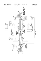
- FIG. 1 shows a simplified cross-sectional view of an arc-discharge chamber.
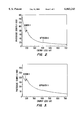
- FIG. 2 shows an EELS spectrum of a boron-nitride standard.
- FIG. 3 shows a TEM-EELS spectrum of an individual boron-nitride tube.
- product means the deposit, or some portion of the deposit, that forms as a result of producing an electrical arc between an anode and a cathode in the presence of materials that assist and/or are ingredients in the chemical reaction.
- FIG. 1 shows a schematic cross-sectional view of the inventive apparatus and electrodes.
- An arc-discharge chamber 10 provides a controllable ambient gas environment. Pressure, temperature, volume and composition of the ambient gas can be controlled.
- the chamber 10 used in the examples below was custom made at the machine shop at the University of California, Berkeley. It can be ordered from a conventional machine shop specializing in vacuum products. A detailed description of the requirements of an arc-discharge chamber can be found in J. P. Hare, H. W. Kroto, and R. Taylor, Preparation and UV/visible Spectra of Fullerenes C60 and C70, Chemical Physics Letters, vol. 177, page 394 (1991), herein incorporated by reference.
- the electrodes 20 and 22 are shown having a first set of conduits 12 for injecting gases into and/or extracting gases from the arc region, and a second set of conduits 14 for efficiently cooling the electrodes. Additionally the anode, electrode 20, has a compound structure. These features are discussed in greater detail below.
- Ambient gas is introduced into the chamber 10 from gas source 16. If more than one ambient gas is used more gas sources are also used.
- the ambient gas acts to modify the kinetics of the reaction that forms the product in the arc region.
- Two gases used in the examples below were helium and nitrogen. Other ambient gases can be used. The choices are obvious to those of skill in the art and include, for example, any of the noble gases.
- the type of ambient gas and pressure inside the chamber affect the product synthesized.
- the chamber pressure was monitored using a standard gas pressure gauge 18. To produce nanotube and nanoparticles, the initial pressure was typically between about 100 and about 1000 torr. In this invention helium was kept near 650 torr. If gas is either added or withdrawn through conduits 12, the pressure in the chamber may change. Similarly, formation of product, or change in temperature can affect the pressure during operation of the inventive apparatus.
- a first electrode is an anode 20.
- the anode 20 can be placed in various positions.
- the anode 20 comprises a conducting material.
- the conducting material can be a metal with a high melting point, such as tungsten or copper.
- the anode 20 may further have a compound element 21 comprising material that assists in forming a product from arcing the anode against the cathode.
- This composite electrode 20 is arced against a second electrode, a cathode 22.
- the cathode 22 is made of any conducting material, for example, copper.
- the electrodes 20 and 22 are placed opposite one another.
- the anode 20 and cathode 22 further comprise concentric feed through conduits 12 in the interior of the electrodes 20 and 22, for injecting material to for extracting material from the arc region.
- the injected material comprises material that assists in forming a product in the arc region or on the cathode.
- the injected material may be a constituent material of the product formed by arcing the anode against the cathode.
- the material may have a fluid or a particulate composition.
- the first set of conduits 12 connect the arc region 23 to a material reservoir 24. Desirable elements may be injected through the conduits in electrodes 20 and 22 in gaseous, liquid, or particulate form.
- Elements that may be injected through conduits 12 include particles such as buckyballs; powders such as cobalt, nickel, or yttrium; gas such as nitrogen, helium, or acetylene; or liquids such as benzene.
- the injected material may comprise a catalyst or may comprise a material that will be an ingredient in the product. Additionally, inert gases may be introduced to change the reaction kinetics.
- either the compound anode 20 or the material injected through either of the electrodes 20 and 22 may be the source of material for product formation in the arc region.
- an electrode may inject into the arc region, a type of gas comprising elements from the group consisting of boron, nitrogen and carbon.
- the anode 20 may or may not include the element injected through the conduits 12 of the cathode 22 and the anode 20.
- the anode may have a compound structure comprising a graphite rod and a boron nitride section and a gas introduced through conduit may comprise nitrogen.
- the material injected through conduits in either of the electrodes 20 and 22 may be a catalyst for product formation.
- An example of particulate matter introduced through conduit 12 is the introduction of C 60 particles into the arc region. If heated to more than 400° C. the C 60 particles can be introduced as a gas.
- a source of electrical energy 26 is applied to the anode 20 and cathode 22.
- the energy must be sufficient enough to generate an arc for forming a deposit inside the chamber 10.
- the source of energy commonly is a power supply, such as an arc welder power supply.
- the electrical current is d.c. between 50 A and 200 A with the gap between the electrodes 20 and 22 maintained such that the voltage is between 10 V and 30 V to form an arc.
- a second set of conduits 14 in the interior of electrodes 20 and 22 are connected to a fluid supply 28 for special cooling of the anode 20 and cathode 22.
- the electrodes 20 and 22 are cooled by having a continuous flow of cold fluid typically ranging from room temperature to -196° C., supplied to a cooling core 13 in the electrode interior through the conduits 14.
- the cooling fluid may comprise any commonly used commercially available coolant, such as, for example, water, liquid nitrogen, ethylene glycol, or other gasses or liquids.
- the conduits 14 are configured to introduce the coolant from its source 28, near the hot end of the electrode and to extract it from the cooler end via exit port 14'.
- a product When the arc is generated in the presence of a compound anode comprising graphite, boron, and nitrogen, in the presence of either helium gas, or more preferably nitrogen gas, a product forms which contains nanoparticles and nanotubes based on compounds of layered sp 2 -bonded B x C y N z .
- the nanoparticles and nanotubes formed within the product deposited on the cathode comprise individual particles and tubes having inner diameters on the order of nanometers. Concentric structures have diameters ranging from several angstroms to thousands of angstroms, and tube lengths have been found between tens of angstroms and longer than 100 microns.
- FIG. 2 shows an EELS spectrum of a BN standard.
- FIG. 3 shows a TEM-EELS spectrum of an individual boron-nitride tube. The boron absorption edge at approximately 180 eV and the nitrogen absorption edge at approximately 400 eV are clearly resolved. Further analysis of EELS spectrum reveals that the tube has the stoichiometry of BN.
- the inventive apparatus has been used extensively to form nanotubes and nanoparticles comprising B x C y N z , where x, y, and z indicate the amount of each element relative to the others. Structures containing carbon are those in which y ⁇ 0. Either x or z may be 0.
- TEM transmission electron microscopy
- EELS electron energy loss spectroscopy
- This composite rod comprised the anode 20 and was arced next to a larger (about 3/4" diameter) graphite cathode 22 at a d.c. current between about 30 A and about 40 A, provided by a d.c. Lincoln Electric Idealarc 250 arc welder power supply.
- the electrodes 20 and 22 can be ordered from any standard supplier of chemicals to laboratories.
- the chamber was filled with helium at about 650 torr.
- the arc gap is maintained as close as possible without extinguishing the arc, typically less than about 1 mm.
- a deposit formed which contained the BC 3 and BC 2 N tubes and particles. This is described in greater detail in a paper by Z. Weng-Sieh et al., Synthesis of B x C y N z nanotubules, Phys Rev B, v 51, 11 229, Apr. 15, 1995, incorporated herein by reference.
- the deposits were analyzed by TEM imaging and by recording EELS spectra, which were fit to boron, carbon, and nitrogen standards.
- the EELS analysis was used to determine that the stoichiometry, which was found to be BC 3 and BC 2 N tubes, (Weng-Sieh et al., Phys Rev B, 51(16):11229, 1995), incorporated herein by reference.
- TEM images show multi-wall, concentric and crystalline particles and tubes.
- the anode 20 was formed by inserting pressed rod of 99.5% insulating BN and having about 1/8" diameter into a hollowed out piece of 1/4" tungsten (o.d. 1/4", i.d. 1/8") and arcing the resulting electrode against a water-cooled 11/8" (o.d.) copper cathode 22 in the arcing chamber.
- the BN used in the compound electrode may be have a purity of only 90%. A purity as low as 50% is workable but the contaminants may adversely affect the product.
- the tugsten portion of the of the compound electrode is preferably 99.99% pure.
- the tungsten may be as low as 90% pure. Lower levels of purity risk contamination of the product.
- a tungsten cathode was used because it has a high melting point and it was thought it would keep the arc stable, however, copper gave more satisfactory results. Additionally, other electronically conducting materials may be used.
- the initial helium pressure inside the chamber which is preferably kept between about 10 and about 1,000 torr, was approximately 650 torr and the current setting on the Lincoln Electric Idealarc 250 welder was set between about 50 A and about 200 A.
- the gap between the electrodes 20 and 22 was maintained such that the voltage was between about 10 and about 30 V. Alternatively, the voltage can be maintained between about 10 V and about 60 V, depending on conditions. Further, the voltage can be maintained between about 15 V and about 35 V.
- the dc current was ramped from about 50 to about 140 A to maintain a potential drop between about 10 and about 30 V between the electrodes.
- the dc current can be ramped between different values, for example between about 30 amps and about 60 amps. Due to the extremely high temperatures in the arc, chunks of molten tungsten were found in the chamber along with soot. Although there was no deposit on the negative electrode, as there was in the case of carbon, an analysis of the dark gray soot collected on the copper electrode revealed a variety of multi-shelled structures, including tubes and particles of boron-nitride.
- TEM Transmission electron microscopy
- gases containing at least one of the elements from the group comprising boron and nitrogen may also be injected through conduits 12 into the arc region to assist in production of particles and tubes having diameters on the order of nanometers, and based on compounds of B x N z .
- gases may be used as a supplement to, or in lieu of, the B x N z component of the anode 20.
- Fine tungsten powder can be injected into the arc region through conduit 12, where it will provide a catalytic function for the reaction.
- High-resolution TEM images showed sharp lattice fringes signifying that the walls of the tubes were crystalline; the distance between BN planes was 3.2 ⁇ which was close to the interlayer spacing in sheets of BN.
- All the tubes were multi-walled with anywhere from about 15 to about 30 layers of BN.
- the tubules had inner diameters between about 1.5 nm and about 2.5 nm, and total lengths were between about 70 nm and about 250 nm.
- the length to width ration varied between about 5 nm and about 18 nm.
- the typical tube had an aspect ration of about 7.
- the growing end of BN nanotubes may be formed by a four-fold BN bond, that is a bond where each boron is bonded to four nitrogens and vice-versa.
- Closing the structure with this bond give rise to a number of interesting configurations, including a ball of B 12 N 12 , which has a diameter of 6 ⁇ , less that that of a buckyball.
- a third type of cap formation has a bump in the outer layers. This interesting feature suggested a competition between the van der Waal forces between layers and the existence of a four-fold or five-fold bond at the point of inflection of the bump.
- BN configured as nano-scale balls were more prevalent in the deposits than BN configured as nano-scale tubes.
- High resolution TEM photographs revealed faceted BN balls which had nearly symmetric structures about the axis of the incident electron beam. This structure had over 30 walls, and the dimensions of the inner space were approximately 1 nm by about 2 nm.
- Some of the balls had a "V” features, unexpected in materials that form large bond angles. The “V” features indicate modified chemical reactivity at the tip. Additionally "V” features are useful in field emission devices (see co-pending application Ser. No. 08/884,450 filed on Jun. 27, 1997, still pending).
- FIG. 2 shows an EELS spectrum of a BN standard.
- FIG. 3 shows a TEM-EELS spectrum of an individual boron-nitride tube. The boron absorption edge at approximately 180 eV and the nitrogen absorption edge at approximately 400 eV are clearly resolved. Further analysis of EELS spectrum reveals that the nanotubes have the stoichiometry of BN.
- the inventive apparatus was used to synthesize tubes and particles composed of CN. A number of different electrode types, arc currents, and gas pressure configurations give favorable results.
- carbon and nitrogen may be introduced into the arc chamber by using a composite anode 20, comprised of a conducting material combined with carbon and nitrogen.
- gases containing at least one of the elements from the group comprising nitrogen and carbon may be injected through conduits 12 into the arc region to assist in production of particles and tubes having diameters on the order of nanometers, and based on compounds of C y N z . These injected gases may be used as a supplement to, or in lieu of, the C y N z component of the anode 20.
- the total pressure in the chamber was kept at about 500 torr, that is the partial pressure of nitrogen, P N2 , and the partial pressure of helium P He , was about 500 torr.
- About 100 amps was passed through an anode comprising a section of 1/4 inch carbon.
- Tubes with stoichiometries of BN, BC 2 N and BC 3 have been clearly identified. Other tube and particle stoichiometries have been produced in the growth chamber. TEM-EELS analysis of these other stoichiometries are currently being analyzed.
- the particles and tubes based on compounds of layered sp 2 -bonded B x C y N z in accordance with this invention have unique electrical and mechanical properties. They have a wide range of applications in various industries including electronic and mechanical. Examples of these applications include, but are not limited to, electrical and structural components for computers, sensors, filters, micromachines, chip interconnects, ultra-small scale devices, cables and high strength mechanical fibers, and dry lubricants.
- the present invention is an apparatus and method for producing nano-scale tubes and particles.
- the apparatus comprises novel electrodes for use in arc discharge techniques.
- the electrodes have interior conduits for delivery and withdrawal of material from the arc region where product is formed.
- the anode is optionally made from more than one material and is termed a compound anode.
- the materials used in the compound anode assist in the reaction that forms product in the arc region of the apparatus.
- the materials assist either by provided reaction product, catalyst, or affecting the reaction kinetics.
- the inventive apparatus is used to produce nanotubes and nanoparticles having a variety of electrical and mechanical properties.
Abstract
Description
Claims (12)
Priority Applications (1)
| Application Number | Priority Date | Filing Date | Title |
|---|---|---|---|
| US08/978,437 US6063243A (en) | 1995-02-14 | 1997-11-25 | Method for making nanotubes and nanoparticles |
Applications Claiming Priority (2)
| Application Number | Priority Date | Filing Date | Title |
|---|---|---|---|
| US38849495A | 1995-02-14 | 1995-02-14 | |
| US08/978,437 US6063243A (en) | 1995-02-14 | 1997-11-25 | Method for making nanotubes and nanoparticles |
Related Parent Applications (1)
| Application Number | Title | Priority Date | Filing Date |
|---|---|---|---|
| US38849495A Continuation-In-Part | 1995-02-14 | 1995-02-14 |
Publications (1)
| Publication Number | Publication Date |
|---|---|
| US6063243A true US6063243A (en) | 2000-05-16 |
Family
ID=46254660
Family Applications (1)
| Application Number | Title | Priority Date | Filing Date |
|---|---|---|---|
| US08/978,437 Expired - Lifetime US6063243A (en) | 1995-02-14 | 1997-11-25 | Method for making nanotubes and nanoparticles |
Country Status (1)
| Country | Link |
|---|---|
| US (1) | US6063243A (en) |
Cited By (88)
| Publication number | Priority date | Publication date | Assignee | Title |
|---|---|---|---|---|
| US6346303B1 (en) * | 1999-01-11 | 2002-02-12 | Han-Chang Shih | Process for synthesizing one-dimensional nanosubstances by electron cyclotron resonance chemical vapor deposition |
| US20020018745A1 (en) * | 2000-04-10 | 2002-02-14 | Herman Frederick James | Net shape manufacturing using carbon nanotubes |
| GB2365876A (en) * | 2000-08-15 | 2002-02-27 | Tetronics Ltd | Making nano-sized powder using a plasma arc reactor |
| WO2002047109A2 (en) | 2000-12-08 | 2002-06-13 | Sony Corporation | Arc electrodes for synthesis of carbon nanostructures |
| US6420092B1 (en) * | 1999-07-14 | 2002-07-16 | Cheng-Jer Yang | Low dielectric constant nanotube |
| US20020100581A1 (en) * | 1999-06-14 | 2002-08-01 | Knowles Timothy R. | Thermal interface |
| WO2002076887A2 (en) | 2001-03-26 | 2002-10-03 | National Research Council Of Canada | Process and apparatus for synthesis of nanotubes |
| US20020172867A1 (en) * | 2001-04-10 | 2002-11-21 | Anglin David L. | Battery cathode |
| US20020177232A1 (en) * | 2001-05-23 | 2002-11-28 | Melker Richard J. | Method and apparatus for detecting illicit substances |
| US20030004426A1 (en) * | 2001-05-24 | 2003-01-02 | Melker Richard J. | Method and apparatus for detecting environmental smoke exposure |
| WO2003008331A1 (en) * | 2001-07-20 | 2003-01-30 | Kh Chemicals Co., Ltd | Preparation of carbon nanotubes |
| US20030097903A1 (en) * | 2000-02-10 | 2003-05-29 | Deegan David Edward | Plasma arc reactor for the production of fine powders |
| US6574130B2 (en) | 2001-07-25 | 2003-06-03 | Nantero, Inc. | Hybrid circuit having nanotube electromechanical memory |
| US20030129119A1 (en) * | 2002-01-07 | 2003-07-10 | Hsin-Tien Chiu | Nanocarbon materials and process for producing the same |
| WO2003064321A1 (en) * | 2002-02-01 | 2003-08-07 | Nanofilm Technologies International Pte Ltd | Production of nanotubes |
| WO2003064029A1 (en) * | 2002-01-28 | 2003-08-07 | Ambp Tech Corporation | Pulsed arc molecular beam process |
| US20030176804A1 (en) * | 2002-01-22 | 2003-09-18 | Melker Richard J. | Method and apparatus for monitoring respiratory gases during anesthesia |
| WO2003082733A2 (en) * | 2002-04-03 | 2003-10-09 | Canterprise Ltd. | Continuous method for producing inorganic nanotubes |
| US20030199172A1 (en) * | 2001-07-25 | 2003-10-23 | Thomas Rueckes | Methods of nanotube films and articles |
| US6643165B2 (en) | 2001-07-25 | 2003-11-04 | Nantero, Inc. | Electromechanical memory having cell selection circuitry constructed with nanotube technology |
| US20030211030A1 (en) * | 2002-05-09 | 2003-11-13 | Smiljanic Olivier | Method and apparatus for producing single-wall carbon nanotubes |
| US20040009353A1 (en) * | 1999-06-14 | 2004-01-15 | Knowles Timothy R. | PCM/aligned fiber composite thermal interface |
| US6706402B2 (en) | 2001-07-25 | 2004-03-16 | Nantero, Inc. | Nanotube films and articles |
| US6716409B2 (en) | 2000-09-18 | 2004-04-06 | President And Fellows Of The Harvard College | Fabrication of nanotube microscopy tips |
| US6730370B1 (en) * | 2000-09-26 | 2004-05-04 | Sveinn Olafsson | Method and apparatus for processing materials by applying a controlled succession of thermal spikes or shockwaves through a growth medium |
| US6740224B1 (en) * | 2001-06-11 | 2004-05-25 | The United States Of America As Represented By The Administrator Of The National Aeronautics And Space Administration | Method of manufacturing carbon nanotubes |
| US6743408B2 (en) | 2000-09-29 | 2004-06-01 | President And Fellows Of Harvard College | Direct growth of nanotubes, and their use in nanotweezers |
| US6744006B2 (en) | 2000-04-10 | 2004-06-01 | Tetronics Limited | Twin plasma torch apparatus |
| US20040164289A1 (en) * | 2001-12-28 | 2004-08-26 | Nantero, Inc. | Electromechanical three-trace junction devices |
| US6784028B2 (en) | 2001-12-28 | 2004-08-31 | Nantero, Inc. | Methods of making electromechanical three-trace junction devices |
| US20040168906A1 (en) * | 2003-02-27 | 2004-09-02 | Fuji Xerox Co., Ltd. | Manufacturing apparatus for carbon nanotube |
| US6796107B2 (en) | 2000-02-29 | 2004-09-28 | Tetronics Limited | Method and apparatus for packaging ultra fine powders into containers |
| US20040214367A1 (en) * | 2001-07-25 | 2004-10-28 | Nantero, Inc. | Electromechanical memory array using nanotube ribbons and method for making same |
| US20050017598A1 (en) * | 2003-07-18 | 2005-01-27 | Zettl Alexander K. | Rotational actuator or motor based on carbon nanotubes |
| US20050037374A1 (en) * | 1999-11-08 | 2005-02-17 | Melker Richard J. | Combined nanotechnology and sensor technologies for simultaneous diagnosis and treatment |
| US6858349B1 (en) | 2000-09-07 | 2005-02-22 | The Gillette Company | Battery cathode |
| US20050054942A1 (en) * | 2002-01-22 | 2005-03-10 | Melker Richard J. | System and method for therapeutic drug monitoring |
| US6884405B2 (en) * | 1999-03-23 | 2005-04-26 | Rosseter Holdings Limited | Method and device for producing higher fullerenes and nanotubes |
| US6884404B2 (en) * | 2000-05-31 | 2005-04-26 | Fuji Xerox Co., Ltd. | Method of manufacturing carbon nanotubes and/or fullerenes, and manufacturing apparatus for the same |
| US20050115932A1 (en) * | 2000-07-10 | 2005-06-02 | Deegan David E. | Method of improving the service life of a plasma torch electrode |
| US20050119364A1 (en) * | 2003-12-01 | 2005-06-02 | Grah Michael D. | Method of increasing the gas transmission rate of a film |
| US20050142313A1 (en) * | 2003-12-31 | 2005-06-30 | Grah Michael D. | Method of shrinking a film |
| EP1553051A1 (en) * | 2002-07-01 | 2005-07-13 | JFE Engineering Corporation | Tapelike material containing carbon nanotube and production method for carbon nanotube and electric field emission type electrode containing the tapelike material and production method therefor |
| US20050172370A1 (en) * | 2003-11-07 | 2005-08-04 | Sajad Haq | Forming nanostructures |
| US20050191757A1 (en) * | 2004-01-20 | 2005-09-01 | Melker Richard J. | Method and apparatus for detecting humans and human remains |
| WO2005097676A2 (en) * | 2004-03-26 | 2005-10-20 | Luna Innovations Incorporated | Method of making multiple carbonaceous nanomaterials |
| US20050233459A1 (en) * | 2003-11-26 | 2005-10-20 | Melker Richard J | Marker detection method and apparatus to monitor drug compliance |
| US20050230240A1 (en) * | 2004-03-09 | 2005-10-20 | Roman Dubrovsky | Method and apparatus for carbon allotropes synthesis |
| US6974706B1 (en) | 2003-01-16 | 2005-12-13 | University Of Florida Research Foundation, Inc. | Application of biosensors for diagnosis and treatment of disease |
| US20060021510A1 (en) * | 2004-07-27 | 2006-02-02 | University Of North Texas | Method and apparatus for hydrogen production from greenhouse gas saturated carbon nanotubes and synthesis of carbon nanostructures therefrom |
| US20060040318A1 (en) * | 2001-05-23 | 2006-02-23 | Melker Richard J | Novel application of nanotechnology and sensor technologies for ex-vivo diagnostics |
| US20060062712A1 (en) * | 2004-09-20 | 2006-03-23 | Pak Chan-Ho | Method of preparing carbon nanocages |
| US20060062734A1 (en) * | 2004-09-20 | 2006-03-23 | Melker Richard J | Methods and systems for preventing diversion of prescription drugs |
| US20060083927A1 (en) * | 2004-10-15 | 2006-04-20 | Zyvex Corporation | Thermal interface incorporating nanotubes |
| US20060104886A1 (en) * | 2004-11-17 | 2006-05-18 | Luna Innovations Incorporated | Pure-chirality carbon nanotubes and methods |
| US20060127299A1 (en) * | 2002-11-15 | 2006-06-15 | Mcgill University | Method for producing carbon nanotubes using a dc non-transferred thermal plasma torch |
| US20060160134A1 (en) * | 2002-10-21 | 2006-07-20 | Melker Richard J | Novel application of biosensors for diagnosis and treatment of disease |
| WO2006093906A2 (en) * | 2005-02-28 | 2006-09-08 | Neal Kalechofsky | Devices, materials and methods to deposit, align and/or position very small particles |
| US7104963B2 (en) * | 2002-01-22 | 2006-09-12 | University Of Florida Research Foundation, Inc. | Method and apparatus for monitoring intravenous (IV) drug concentration using exhaled breath |
| US20060213599A1 (en) * | 1999-06-14 | 2006-09-28 | Knowles Timothy R | Fiber adhesive material |
| US20060257883A1 (en) * | 2005-05-10 | 2006-11-16 | Bjoraker David G | Detection and measurement of hematological parameters characterizing cellular blood components |
| US20070042089A1 (en) * | 2005-08-19 | 2007-02-22 | Cryovac, Inc. | Increasing the gas transmission rate of a film comprising fullerenes |
| US20070040112A1 (en) * | 2005-01-26 | 2007-02-22 | Lothar Rottmann | Glow discharge source |
| US20070167853A1 (en) * | 2002-01-22 | 2007-07-19 | Melker Richard J | System and method for monitoring health using exhaled breath |
| US20070275273A1 (en) * | 2004-03-26 | 2007-11-29 | Luna Innovations Incorporated | Trimetaspheres for Ion Selective Membranes |
| US20070285787A1 (en) * | 2004-03-26 | 2007-12-13 | Klemer Daniel R | Optical Limiter Having Trimetallic Nitride Endohedral Metallofullerence Films |
| US20070292698A1 (en) * | 2004-03-26 | 2007-12-20 | Luna Innovations Incorporated | Trimetaspheres as Dry Lubricants, Wet Lubricants, Lubricant Additives, Lubricant Coatings, Corrosion-Resistant Coatings and Thermally-Conductive Materials |
| US20070295395A1 (en) * | 2004-03-26 | 2007-12-27 | Luna Innovations Incorporated | Photovoltaic Device With Trimetaspheres |
| US20080045825A1 (en) * | 2006-08-15 | 2008-02-21 | Melker Richard J | Condensate glucose analyzer |
| US20080085234A1 (en) * | 2005-01-03 | 2008-04-10 | Luna Innovations | Chemical separation method for fullerenes |
| US20080142757A1 (en) * | 2006-12-13 | 2008-06-19 | E. I. Dupont De Nemours And Company | Alloyed nanophenes |
| US20080166285A1 (en) * | 2004-03-26 | 2008-07-10 | Luna Innovations Incorporated | Pegylation and Hydroxylation of Trimetallic Nitride Endohedral Metallofullerenes |
| US20080185560A1 (en) * | 2006-12-13 | 2008-08-07 | E. I. Dupont De Nemours And Company | Composition containing alloyed nanophene moieties |
| US20080299307A1 (en) * | 2001-07-25 | 2008-12-04 | Ward Jonathan W | Methods of making carbon nanotube films, layers, fabrics, ribbons, elements and articles |
| US20090012276A1 (en) * | 2004-03-26 | 2009-01-08 | Zhongxin Ge | Polyhydroxy Hydrogensulfated Trimetallic Nitride Endohedral Metallofullerenes |
| CN100453455C (en) * | 2005-06-30 | 2009-01-21 | 鸿富锦精密工业(深圳)有限公司 | Nano carbon material synthesizing device and method |
| US20090038958A1 (en) * | 2007-07-06 | 2009-02-12 | Coyle Edward L | Method and Apparatus for a Low Cost and Carbon Free Point of Use Dissociation of Water into Elemental Gases and Production of Hydrogen Related Power |
| US20090068461A1 (en) * | 2003-10-16 | 2009-03-12 | The University Of Akron | Carbon nanotubes on carbon nanofiber substrate |
| US20090214799A1 (en) * | 2005-03-14 | 2009-08-27 | Benoit Simard | Method and Apparatus for the Continuous Production and Functionalization of Single-Walled Carbon Nanotubes Using a High Frequency Plasma Torch |
| US7820108B2 (en) | 1999-11-08 | 2010-10-26 | University Of Florida Research Foundation, Inc. | Marker detection method and apparatus to monitor drug compliance |
| US7919037B1 (en) | 2005-01-19 | 2011-04-05 | Darren Boyce | Process and composition for molding heatable articles and resulting product |
| EA016164B1 (en) * | 2010-12-28 | 2012-02-28 | Федеральное Государственное Учреждение "Научно-Производственный Комплекс "Технологический Центр" Московского Государственного Института Электронной Техники" | Method of forming carbonic nanostructures and nanostructures produced by the method |
| RU2478572C2 (en) * | 2011-01-30 | 2013-04-10 | Мсд Текнолоджис Частная Компания С Ограниченной Ответственностью | Method of obtaining carbon nanotubes and reactor (versions) |
| WO2014152062A3 (en) * | 2013-03-15 | 2014-11-13 | Luna Innovations Incorporated | Methods and devices for the synthesis of metallofullerenes |
| US9394632B2 (en) | 2010-03-22 | 2016-07-19 | The Regents Of The University Of California | Method and device to synthesize boron nitride nanotubes and related nanoparticles |
| RU175915U1 (en) * | 2017-08-25 | 2017-12-22 | Общество с ограниченной ответственностью "АГНИ-К" | Graphene hydrogenation device during its synthesis |
| CN108046237A (en) * | 2017-12-15 | 2018-05-18 | 中国石油大学(北京) | Arc light plasma prepares the device of carbon nanomaterial |
| WO2021105860A1 (en) | 2019-11-26 | 2021-06-03 | Trimtabs Ltd | Cables and methods of their production |
Citations (2)
| Publication number | Priority date | Publication date | Assignee | Title |
|---|---|---|---|---|
| US4412899A (en) * | 1983-02-07 | 1983-11-01 | Applied Coatings International, Inc. | Cubic boron nitride preparation utilizing nitrogen gas |
| US5876684A (en) * | 1992-08-14 | 1999-03-02 | Materials And Electrochemical Research (Mer) Corporation | Methods and apparati for producing fullerenes |
-
1997
- 1997-11-25 US US08/978,437 patent/US6063243A/en not_active Expired - Lifetime
Patent Citations (2)
| Publication number | Priority date | Publication date | Assignee | Title |
|---|---|---|---|---|
| US4412899A (en) * | 1983-02-07 | 1983-11-01 | Applied Coatings International, Inc. | Cubic boron nitride preparation utilizing nitrogen gas |
| US5876684A (en) * | 1992-08-14 | 1999-03-02 | Materials And Electrochemical Research (Mer) Corporation | Methods and apparati for producing fullerenes |
Non-Patent Citations (2)
| Title |
|---|
| Ebesen et al., "Large-Scale Synthesis of Carbon Nanotubes"; Nature, vol. 358, Jul. 16, 1992. pp. 220-223. |
| Ebesen et al., Large Scale Synthesis of Carbon Nanotubes ; Nature, vol. 358, Jul. 16, 1992. pp. 220 223. * |
Cited By (161)
| Publication number | Priority date | Publication date | Assignee | Title |
|---|---|---|---|---|
| US6346303B1 (en) * | 1999-01-11 | 2002-02-12 | Han-Chang Shih | Process for synthesizing one-dimensional nanosubstances by electron cyclotron resonance chemical vapor deposition |
| US6884405B2 (en) * | 1999-03-23 | 2005-04-26 | Rosseter Holdings Limited | Method and device for producing higher fullerenes and nanotubes |
| US6913075B1 (en) | 1999-06-14 | 2005-07-05 | Energy Science Laboratories, Inc. | Dendritic fiber material |
| US20060213599A1 (en) * | 1999-06-14 | 2006-09-28 | Knowles Timothy R | Fiber adhesive material |
| US7132161B2 (en) | 1999-06-14 | 2006-11-07 | Energy Science Laboratories, Inc. | Fiber adhesive material |
| US7144624B2 (en) | 1999-06-14 | 2006-12-05 | Energy Science Laboratories, Inc. | Dendritic fiber material |
| US20020100581A1 (en) * | 1999-06-14 | 2002-08-01 | Knowles Timothy R. | Thermal interface |
| US20040009353A1 (en) * | 1999-06-14 | 2004-01-15 | Knowles Timothy R. | PCM/aligned fiber composite thermal interface |
| US6420092B1 (en) * | 1999-07-14 | 2002-07-16 | Cheng-Jer Yang | Low dielectric constant nanotube |
| US20050037374A1 (en) * | 1999-11-08 | 2005-02-17 | Melker Richard J. | Combined nanotechnology and sensor technologies for simultaneous diagnosis and treatment |
| US7820108B2 (en) | 1999-11-08 | 2010-10-26 | University Of Florida Research Foundation, Inc. | Marker detection method and apparatus to monitor drug compliance |
| US20060096417A1 (en) * | 2000-02-10 | 2006-05-11 | Tetronics Limited | Plasma arc reactor for the production of fine powders |
| US20060107789A1 (en) * | 2000-02-10 | 2006-05-25 | Tetronics Limited | Plasma arc reactor for the production of fine powders |
| US20030097903A1 (en) * | 2000-02-10 | 2003-05-29 | Deegan David Edward | Plasma arc reactor for the production of fine powders |
| US7727460B2 (en) | 2000-02-10 | 2010-06-01 | Tetronics Limited | Plasma arc reactor for the production of fine powders |
| US7022155B2 (en) | 2000-02-10 | 2006-04-04 | Tetronics Limited | Plasma arc reactor for the production of fine powders |
| US6796107B2 (en) | 2000-02-29 | 2004-09-28 | Tetronics Limited | Method and apparatus for packaging ultra fine powders into containers |
| US20020018745A1 (en) * | 2000-04-10 | 2002-02-14 | Herman Frederick James | Net shape manufacturing using carbon nanotubes |
| US6744006B2 (en) | 2000-04-10 | 2004-06-01 | Tetronics Limited | Twin plasma torch apparatus |
| US6884404B2 (en) * | 2000-05-31 | 2005-04-26 | Fuji Xerox Co., Ltd. | Method of manufacturing carbon nanotubes and/or fullerenes, and manufacturing apparatus for the same |
| US20050115932A1 (en) * | 2000-07-10 | 2005-06-02 | Deegan David E. | Method of improving the service life of a plasma torch electrode |
| GB2365876A (en) * | 2000-08-15 | 2002-02-27 | Tetronics Ltd | Making nano-sized powder using a plasma arc reactor |
| US6858349B1 (en) | 2000-09-07 | 2005-02-22 | The Gillette Company | Battery cathode |
| US6716409B2 (en) | 2000-09-18 | 2004-04-06 | President And Fellows Of The Harvard College | Fabrication of nanotube microscopy tips |
| US20040221812A1 (en) * | 2000-09-26 | 2004-11-11 | Sveinn Olafsson | Method and apparatus for processing materials by applying a controlled succession of thermal spikes or shockwaves through a growth medium |
| US6730370B1 (en) * | 2000-09-26 | 2004-05-04 | Sveinn Olafsson | Method and apparatus for processing materials by applying a controlled succession of thermal spikes or shockwaves through a growth medium |
| US6743408B2 (en) | 2000-09-29 | 2004-06-01 | President And Fellows Of Harvard College | Direct growth of nanotubes, and their use in nanotweezers |
| JP4604342B2 (en) * | 2000-12-08 | 2011-01-05 | ソニー株式会社 | Arc electrode for synthesis of carbon nanostructures |
| US20040050686A1 (en) * | 2000-12-08 | 2004-03-18 | Houjin Huang | Arc electrodes for synthesis of carbon nanostructures |
| CN1293595C (en) * | 2000-12-08 | 2007-01-03 | 索尼公司 | Arc electrodes for synthesis of carbon nanostructures |
| WO2002047109A2 (en) | 2000-12-08 | 2002-06-13 | Sony Corporation | Arc electrodes for synthesis of carbon nanostructures |
| JP2002179417A (en) * | 2000-12-08 | 2002-06-26 | Sony Corp | Arc electrode for synthesis of carbon nano-structure |
| KR100837221B1 (en) | 2000-12-08 | 2008-06-12 | 소니 가부시키가이샤 | Arc electrode assembly for producing carbon nanostructures and method for producing carbon nanostructures |
| EP2242088A2 (en) | 2000-12-08 | 2010-10-20 | Sony Corporation | Arc electrodes for synthesis of carbon nanostructures |
| EP2242088A3 (en) * | 2000-12-08 | 2010-10-27 | Sony Corporation | Arc electrodes for synthesis of carbon nanostructures |
| WO2002047109A3 (en) * | 2000-12-08 | 2002-09-19 | Sony Corp | Arc electrodes for synthesis of carbon nanostructures |
| US6794598B2 (en) | 2000-12-08 | 2004-09-21 | Sony Corporation | Arc electrodes for synthesis of carbon nanostructures |
| US20040109814A1 (en) * | 2001-03-26 | 2004-06-10 | Benoit Simard | Process and apparatus for synthesis of nanotubes |
| WO2002076887A2 (en) | 2001-03-26 | 2002-10-03 | National Research Council Of Canada | Process and apparatus for synthesis of nanotubes |
| US7374730B2 (en) | 2001-03-26 | 2008-05-20 | National Research Council Of Canada | Process and apparatus for synthesis of nanotubes |
| US20020172867A1 (en) * | 2001-04-10 | 2002-11-21 | Anglin David L. | Battery cathode |
| US6613198B2 (en) * | 2001-04-18 | 2003-09-02 | James F. Garvey | Pulsed arc molecular beam process |
| US20020177232A1 (en) * | 2001-05-23 | 2002-11-28 | Melker Richard J. | Method and apparatus for detecting illicit substances |
| US20060040318A1 (en) * | 2001-05-23 | 2006-02-23 | Melker Richard J | Novel application of nanotechnology and sensor technologies for ex-vivo diagnostics |
| US7052854B2 (en) | 2001-05-23 | 2006-05-30 | University Of Florida Research Foundation, Inc. | Application of nanotechnology and sensor technologies for ex-vivo diagnostics |
| US7052468B2 (en) | 2001-05-24 | 2006-05-30 | University Of Florida Research Foundation, Inc. | Method and apparatus for detecting environmental smoke exposure |
| US20030004426A1 (en) * | 2001-05-24 | 2003-01-02 | Melker Richard J. | Method and apparatus for detecting environmental smoke exposure |
| US6740224B1 (en) * | 2001-06-11 | 2004-05-25 | The United States Of America As Represented By The Administrator Of The National Aeronautics And Space Administration | Method of manufacturing carbon nanotubes |
| WO2003008331A1 (en) * | 2001-07-20 | 2003-01-30 | Kh Chemicals Co., Ltd | Preparation of carbon nanotubes |
| US7745810B2 (en) | 2001-07-25 | 2010-06-29 | Nantero, Inc. | Nanotube films and articles |
| US6836424B2 (en) | 2001-07-25 | 2004-12-28 | Nantero, Inc. | Hybrid circuit having nanotube electromechanical memory |
| US20050063210A1 (en) * | 2001-07-25 | 2005-03-24 | Nantero, Inc. | Hybrid circuit having nanotube electromechanical memory |
| US20040214367A1 (en) * | 2001-07-25 | 2004-10-28 | Nantero, Inc. | Electromechanical memory array using nanotube ribbons and method for making same |
| US20040214366A1 (en) * | 2001-07-25 | 2004-10-28 | Nantero, Inc. | Electromechanical memory array using nanotube ribbons and method for making same |
| US20080299307A1 (en) * | 2001-07-25 | 2008-12-04 | Ward Jonathan W | Methods of making carbon nanotube films, layers, fabrics, ribbons, elements and articles |
| US20070141746A1 (en) * | 2001-07-25 | 2007-06-21 | Nantero, Inc. | Methods of nanotube films and articles |
| US6574130B2 (en) | 2001-07-25 | 2003-06-03 | Nantero, Inc. | Hybrid circuit having nanotube electromechanical memory |
| US20030199172A1 (en) * | 2001-07-25 | 2003-10-23 | Thomas Rueckes | Methods of nanotube films and articles |
| US6643165B2 (en) | 2001-07-25 | 2003-11-04 | Nantero, Inc. | Electromechanical memory having cell selection circuitry constructed with nanotube technology |
| US6706402B2 (en) | 2001-07-25 | 2004-03-16 | Nantero, Inc. | Nanotube films and articles |
| US8101976B2 (en) | 2001-07-25 | 2012-01-24 | Nantero Inc. | Device selection circuitry constructed with nanotube ribbon technology |
| US20040085805A1 (en) * | 2001-07-25 | 2004-05-06 | Nantero, Inc. | Device selection circuitry constructed with nanotube technology |
| US20030165074A1 (en) * | 2001-07-25 | 2003-09-04 | Nantero, Inc. | Hybrid circuit having nanotube electromechanical memory |
| US20050191495A1 (en) * | 2001-07-25 | 2005-09-01 | Nantero, Inc. | Nanotube films and articles |
| US6835591B2 (en) | 2001-07-25 | 2004-12-28 | Nantero, Inc. | Methods of nanotube films and articles |
| US7915066B2 (en) | 2001-12-28 | 2011-03-29 | Nantero, Inc. | Methods of making electromechanical three-trace junction devices |
| US6784028B2 (en) | 2001-12-28 | 2004-08-31 | Nantero, Inc. | Methods of making electromechanical three-trace junction devices |
| US20040164289A1 (en) * | 2001-12-28 | 2004-08-26 | Nantero, Inc. | Electromechanical three-trace junction devices |
| US20040191978A1 (en) * | 2001-12-28 | 2004-09-30 | Nantero, Inc. | Methods of making electromechanical three-trace junction devices |
| US20030129119A1 (en) * | 2002-01-07 | 2003-07-10 | Hsin-Tien Chiu | Nanocarbon materials and process for producing the same |
| US6981947B2 (en) | 2002-01-22 | 2006-01-03 | University Of Florida Research Foundation, Inc. | Method and apparatus for monitoring respiratory gases during anesthesia |
| US20070167853A1 (en) * | 2002-01-22 | 2007-07-19 | Melker Richard J | System and method for monitoring health using exhaled breath |
| US20050054942A1 (en) * | 2002-01-22 | 2005-03-10 | Melker Richard J. | System and method for therapeutic drug monitoring |
| US7104963B2 (en) * | 2002-01-22 | 2006-09-12 | University Of Florida Research Foundation, Inc. | Method and apparatus for monitoring intravenous (IV) drug concentration using exhaled breath |
| US20070203448A1 (en) * | 2002-01-22 | 2007-08-30 | Melker Richard J | System and method for monitoring health using exhaled breath |
| US20030176804A1 (en) * | 2002-01-22 | 2003-09-18 | Melker Richard J. | Method and apparatus for monitoring respiratory gases during anesthesia |
| US8211035B2 (en) | 2002-01-22 | 2012-07-03 | University Of Florida Research Foundation, Inc. | System and method for monitoring health using exhaled breath |
| WO2003064029A1 (en) * | 2002-01-28 | 2003-08-07 | Ambp Tech Corporation | Pulsed arc molecular beam process |
| WO2003064321A1 (en) * | 2002-02-01 | 2003-08-07 | Nanofilm Technologies International Pte Ltd | Production of nanotubes |
| US20050115821A1 (en) * | 2002-02-01 | 2005-06-02 | Xu Shi | Production of nanotubes |
| WO2003082733A3 (en) * | 2002-04-03 | 2003-11-27 | Canterprise Ltd | Continuous method for producing inorganic nanotubes |
| US20060165914A1 (en) * | 2002-04-03 | 2006-07-27 | John Abrahamson | Continuous method for producing inorganic nanotubes |
| WO2003082733A2 (en) * | 2002-04-03 | 2003-10-09 | Canterprise Ltd. | Continuous method for producing inorganic nanotubes |
| US20080124482A1 (en) * | 2002-05-09 | 2008-05-29 | Olivier Smiljanic | Method and apparatus for producing single-wall carbon nanotubes |
| US20030211030A1 (en) * | 2002-05-09 | 2003-11-13 | Smiljanic Olivier | Method and apparatus for producing single-wall carbon nanotubes |
| US8071906B2 (en) | 2002-05-09 | 2011-12-06 | Institut National De La Recherche Scientifique | Apparatus for producing single-wall carbon nanotubes |
| US20100300358A1 (en) * | 2002-05-09 | 2010-12-02 | Olivier Smiljanic | Apparatus for producing single-wall carbon nanotubes |
| US7591989B2 (en) | 2002-05-09 | 2009-09-22 | Institut National De La Recherche Scientifique | Method and apparatus for producing single-wall carbon nanotubes |
| US20080226536A1 (en) * | 2002-05-09 | 2008-09-18 | Olivier Smiljanic | Method and apparatus for producing single-wall carbon nanotubes |
| EP1553051A1 (en) * | 2002-07-01 | 2005-07-13 | JFE Engineering Corporation | Tapelike material containing carbon nanotube and production method for carbon nanotube and electric field emission type electrode containing the tapelike material and production method therefor |
| EP1553051A4 (en) * | 2002-07-01 | 2011-05-18 | Jfe Eng Corp | Tapelike material containing carbon nanotube and production method for carbon nanotube and electric field emission type electrode containing the tapelike material and production method therefor |
| US20060160134A1 (en) * | 2002-10-21 | 2006-07-20 | Melker Richard J | Novel application of biosensors for diagnosis and treatment of disease |
| US7846414B2 (en) | 2002-11-15 | 2010-12-07 | Mcgill University | Method for producing carbon nanotubes using a DC non-transferred thermal plasma torch |
| US20060127299A1 (en) * | 2002-11-15 | 2006-06-15 | Mcgill University | Method for producing carbon nanotubes using a dc non-transferred thermal plasma torch |
| US6974706B1 (en) | 2003-01-16 | 2005-12-13 | University Of Florida Research Foundation, Inc. | Application of biosensors for diagnosis and treatment of disease |
| US6936228B2 (en) * | 2003-02-27 | 2005-08-30 | Fuji Xerox Co., Ltd. | Manufacturing apparatus for carbon nanotube |
| US20040168906A1 (en) * | 2003-02-27 | 2004-09-02 | Fuji Xerox Co., Ltd. | Manufacturing apparatus for carbon nanotube |
| US20050017598A1 (en) * | 2003-07-18 | 2005-01-27 | Zettl Alexander K. | Rotational actuator or motor based on carbon nanotubes |
| US7053520B2 (en) | 2003-07-18 | 2006-05-30 | The Regents Of The University Of California | Rotational actuator or motor based on carbon nanotubes |
| US7453183B2 (en) | 2003-07-18 | 2008-11-18 | The Regents Of The University Of California | Rotational actuator of motor based on carbon nanotubes |
| US20090068461A1 (en) * | 2003-10-16 | 2009-03-12 | The University Of Akron | Carbon nanotubes on carbon nanofiber substrate |
| US7794784B2 (en) | 2003-11-07 | 2010-09-14 | Bae Systems Plc | Forming nanostructures |
| US20050172370A1 (en) * | 2003-11-07 | 2005-08-04 | Sajad Haq | Forming nanostructures |
| US20050233459A1 (en) * | 2003-11-26 | 2005-10-20 | Melker Richard J | Marker detection method and apparatus to monitor drug compliance |
| US20050119364A1 (en) * | 2003-12-01 | 2005-06-02 | Grah Michael D. | Method of increasing the gas transmission rate of a film |
| US7163967B2 (en) | 2003-12-01 | 2007-01-16 | Cryovac, Inc. | Method of increasing the gas transmission rate of a film |
| US20050142313A1 (en) * | 2003-12-31 | 2005-06-30 | Grah Michael D. | Method of shrinking a film |
| US7335327B2 (en) | 2003-12-31 | 2008-02-26 | Cryovac, Inc. | Method of shrinking a film |
| US20050191757A1 (en) * | 2004-01-20 | 2005-09-01 | Melker Richard J. | Method and apparatus for detecting humans and human remains |
| EP1990639A1 (en) | 2004-02-26 | 2008-11-12 | University Of Florida Research Foundation, Inc. | System and method for real-time diagnosis, treatment, and therapeutic drug monitoring |
| US20050230240A1 (en) * | 2004-03-09 | 2005-10-20 | Roman Dubrovsky | Method and apparatus for carbon allotropes synthesis |
| US8119092B2 (en) | 2004-03-26 | 2012-02-21 | Luna Innovations Incorporated | Pegylation and hydroxylation of trimetallic nitride endohedral metallofullerenes |
| US20070295395A1 (en) * | 2004-03-26 | 2007-12-27 | Luna Innovations Incorporated | Photovoltaic Device With Trimetaspheres |
| US20080166285A1 (en) * | 2004-03-26 | 2008-07-10 | Luna Innovations Incorporated | Pegylation and Hydroxylation of Trimetallic Nitride Endohedral Metallofullerenes |
| US20070292698A1 (en) * | 2004-03-26 | 2007-12-20 | Luna Innovations Incorporated | Trimetaspheres as Dry Lubricants, Wet Lubricants, Lubricant Additives, Lubricant Coatings, Corrosion-Resistant Coatings and Thermally-Conductive Materials |
| US20070285787A1 (en) * | 2004-03-26 | 2007-12-13 | Klemer Daniel R | Optical Limiter Having Trimetallic Nitride Endohedral Metallofullerence Films |
| US20070275273A1 (en) * | 2004-03-26 | 2007-11-29 | Luna Innovations Incorporated | Trimetaspheres for Ion Selective Membranes |
| US20080031795A1 (en) * | 2004-03-26 | 2008-02-07 | Luna Innovations Incorporated | Method of Making Multiple Carbonaceous Nanomaterials |
| WO2005097676A3 (en) * | 2004-03-26 | 2006-01-12 | Luna Innovations Inc | Method of making multiple carbonaceous nanomaterials |
| US20090012276A1 (en) * | 2004-03-26 | 2009-01-08 | Zhongxin Ge | Polyhydroxy Hydrogensulfated Trimetallic Nitride Endohedral Metallofullerenes |
| WO2005097676A2 (en) * | 2004-03-26 | 2005-10-20 | Luna Innovations Incorporated | Method of making multiple carbonaceous nanomaterials |
| US7570411B2 (en) | 2004-03-26 | 2009-08-04 | Luna Innovations Incorporated | Optical limiter having trimetallic nitride endohedral metallofullerence films |
| US20060021510A1 (en) * | 2004-07-27 | 2006-02-02 | University Of North Texas | Method and apparatus for hydrogen production from greenhouse gas saturated carbon nanotubes and synthesis of carbon nanostructures therefrom |
| US7468097B2 (en) | 2004-07-27 | 2008-12-23 | University Of North Texas | Method and apparatus for hydrogen production from greenhouse gas saturated carbon nanotubes and synthesis of carbon nanostructures therefrom |
| US20060062734A1 (en) * | 2004-09-20 | 2006-03-23 | Melker Richard J | Methods and systems for preventing diversion of prescription drugs |
| US20080059226A1 (en) * | 2004-09-20 | 2008-03-06 | Melker Richard J | Methods and Systems for Preventing Diversion Of Prescription Drugs |
| US7518045B2 (en) | 2004-09-20 | 2009-04-14 | Samsung Sdi Co., Ltd. | Method of preparing carbon nanocages |
| US20060062712A1 (en) * | 2004-09-20 | 2006-03-23 | Pak Chan-Ho | Method of preparing carbon nanocages |
| CN100391831C (en) * | 2004-09-20 | 2008-06-04 | 三星Sdi株式会社 | Method of preparing carbon nanocages |
| US20060083927A1 (en) * | 2004-10-15 | 2006-04-20 | Zyvex Corporation | Thermal interface incorporating nanotubes |
| US20060104886A1 (en) * | 2004-11-17 | 2006-05-18 | Luna Innovations Incorporated | Pure-chirality carbon nanotubes and methods |
| US20080085234A1 (en) * | 2005-01-03 | 2008-04-10 | Luna Innovations | Chemical separation method for fullerenes |
| US7919037B1 (en) | 2005-01-19 | 2011-04-05 | Darren Boyce | Process and composition for molding heatable articles and resulting product |
| US7456395B2 (en) * | 2005-01-26 | 2008-11-25 | Thermo Electron (Bremen) Gmbh | Glow discharge source |
| US20070040112A1 (en) * | 2005-01-26 | 2007-02-22 | Lothar Rottmann | Glow discharge source |
| WO2006093906A2 (en) * | 2005-02-28 | 2006-09-08 | Neal Kalechofsky | Devices, materials and methods to deposit, align and/or position very small particles |
| WO2006093906A3 (en) * | 2005-02-28 | 2007-06-14 | Neal Kalechofsky | Devices, materials and methods to deposit, align and/or position very small particles |
| US8834827B2 (en) | 2005-03-14 | 2014-09-16 | National Research Council Of Canada | Method and apparatus for the continuous production and functionalization of single-walled carbon nanotubes using a high frequency plasma torch |
| US20090214799A1 (en) * | 2005-03-14 | 2009-08-27 | Benoit Simard | Method and Apparatus for the Continuous Production and Functionalization of Single-Walled Carbon Nanotubes Using a High Frequency Plasma Torch |
| US20060257883A1 (en) * | 2005-05-10 | 2006-11-16 | Bjoraker David G | Detection and measurement of hematological parameters characterizing cellular blood components |
| CN100453455C (en) * | 2005-06-30 | 2009-01-21 | 鸿富锦精密工业(深圳)有限公司 | Nano carbon material synthesizing device and method |
| US20070042089A1 (en) * | 2005-08-19 | 2007-02-22 | Cryovac, Inc. | Increasing the gas transmission rate of a film comprising fullerenes |
| US7678841B2 (en) | 2005-08-19 | 2010-03-16 | Cryovac, Inc. | Increasing the gas transmission rate of a film comprising fullerenes |
| US7914460B2 (en) | 2006-08-15 | 2011-03-29 | University Of Florida Research Foundation, Inc. | Condensate glucose analyzer |
| US20080045825A1 (en) * | 2006-08-15 | 2008-02-21 | Melker Richard J | Condensate glucose analyzer |
| US7476340B2 (en) | 2006-12-13 | 2009-01-13 | E. I. Du Pont De Nemours & Company | Composition containing alloyed nanophene moieties |
| US20080185560A1 (en) * | 2006-12-13 | 2008-08-07 | E. I. Dupont De Nemours And Company | Composition containing alloyed nanophene moieties |
| US20080142757A1 (en) * | 2006-12-13 | 2008-06-19 | E. I. Dupont De Nemours And Company | Alloyed nanophenes |
| EP2167422A1 (en) * | 2007-07-06 | 2010-03-31 | Evaco, Llc. | Carbon free dissociation of water and production of hydrogen related power |
| EP2167422A4 (en) * | 2007-07-06 | 2012-06-20 | Evaco Llc | Carbon free dissociation of water and production of hydrogen related power |
| US20090038958A1 (en) * | 2007-07-06 | 2009-02-12 | Coyle Edward L | Method and Apparatus for a Low Cost and Carbon Free Point of Use Dissociation of Water into Elemental Gases and Production of Hydrogen Related Power |
| US9994450B2 (en) | 2007-07-06 | 2018-06-12 | Evaco, Llc | Method and apparatus for a low cost and carbon free point of use dissociation of water into elemental gases and production of hydrogen related power |
| US9394632B2 (en) | 2010-03-22 | 2016-07-19 | The Regents Of The University Of California | Method and device to synthesize boron nitride nanotubes and related nanoparticles |
| US10596542B2 (en) | 2010-03-22 | 2020-03-24 | The Regents Of The University Of California | Method and device to synthesize boron nitride nanotubes and related nanoparticles |
| EA016164B1 (en) * | 2010-12-28 | 2012-02-28 | Федеральное Государственное Учреждение "Научно-Производственный Комплекс "Технологический Центр" Московского Государственного Института Электронной Техники" | Method of forming carbonic nanostructures and nanostructures produced by the method |
| RU2478572C2 (en) * | 2011-01-30 | 2013-04-10 | Мсд Текнолоджис Частная Компания С Ограниченной Ответственностью | Method of obtaining carbon nanotubes and reactor (versions) |
| WO2014152062A3 (en) * | 2013-03-15 | 2014-11-13 | Luna Innovations Incorporated | Methods and devices for the synthesis of metallofullerenes |
| RU175915U1 (en) * | 2017-08-25 | 2017-12-22 | Общество с ограниченной ответственностью "АГНИ-К" | Graphene hydrogenation device during its synthesis |
| CN108046237A (en) * | 2017-12-15 | 2018-05-18 | 中国石油大学(北京) | Arc light plasma prepares the device of carbon nanomaterial |
| CN108046237B (en) * | 2017-12-15 | 2019-12-13 | 中国石油大学(北京) | Device for preparing carbon nano material by arc plasma |
| WO2021105860A1 (en) | 2019-11-26 | 2021-06-03 | Trimtabs Ltd | Cables and methods of their production |
Similar Documents
| Publication | Publication Date | Title |
|---|---|---|
| US6063243A (en) | Method for making nanotubes and nanoparticles | |
| US6455021B1 (en) | Method for producing carbon nanotubes | |
| Lange et al. | Nanocarbon production by arc discharge in water | |
| US7938987B2 (en) | Organized carbon and non-carbon assembly and methods of making | |
| Mathur et al. | Co-synthesis, purification and characterization of single-and multi-walled carbon nanotubes using the electric arc method | |
| US7056479B2 (en) | Process for preparing carbon nanotubes | |
| Journet et al. | Production of carbon nanotubes. | |
| Ugarte et al. | Filling carbon nanotubes. | |
| US6884404B2 (en) | Method of manufacturing carbon nanotubes and/or fullerenes, and manufacturing apparatus for the same | |
| Yu et al. | Simultaneous synthesis of carbon nanotubes and nitrogen-doped fullerenes in nitrogen atmosphere | |
| Tarasov et al. | Synthesis of carbon nanostructures by arc evaporation of graphite rods with Co–Ni and YNi2 catalysts | |
| Okuno et al. | Synthesis of carbon nanotubes and nano-necklaces by thermal plasma process | |
| US20040258604A1 (en) | Apparatus and method for nanoparticle and nanotube production and use therefor for gas storage | |
| AU2002326021A1 (en) | Apparatus and method for nanoparticle and nanotube production, and use therefor for gas storage | |
| JPH11116218A (en) | Production of single layered nanotube | |
| US7955663B2 (en) | Process for the simultaneous and selective preparation of single-walled and multi-walled carbon nanotubes | |
| Journet et al. | Single wall carbon nanotubes: Two ways of production | |
| Zhang et al. | The effect of helium gas pressure on the formation and yield of nanotubes in arc discharge | |
| KR101972659B1 (en) | Method for manufacturing rod-like carbon-germanium composite and rod-like carbon-germanium composite | |
| Srivastava et al. | Effect of external electric field on the growth of nanotubules | |
| Duncan et al. | Manufacture of Carbon Multi-Walled Nanotubes by the Arc Discharge Technique. | |
| Bhartiya et al. | Synthesis methods of nanotubes | |
| Bezmel’nitsyn et al. | Preparation of single-walled nanotubes with the help of a Ni/Cr-based catalyst | |
| US10822236B2 (en) | Method of manufacturing carbon nanotubes using electric arc discharge | |
| Fengqiu et al. | Mechanosynthesis of boron nitride nanotubes |
Legal Events
| Date | Code | Title | Description |
|---|---|---|---|
| AS | Assignment |
Owner name: CALIFORNIA, UNIVERSITY OF, REGENTS OF THE, THE, CA Free format text: ASSIGNMENT OF ASSIGNORS INTEREST;ASSIGNORS:ZETTL, ALEXANDER KARLWALTER;COHEN, MARVIN LOU;REEL/FRAME:008898/0885 Effective date: 19971126 |
|
| STCF | Information on status: patent grant |
Free format text: PATENTED CASE |
|
| AS | Assignment |
Owner name: ENERGY, U.S. DEPARTMENT OF, CALIFORNIA Free format text: CONFIRMATORY LICENSE;ASSIGNOR:CALIFORNIA, REGENTS OF THE UNIVERSIT OF;REEL/FRAME:012822/0197 Effective date: 20010712 |
|
| FPAY | Fee payment |
Year of fee payment: 4 |
|
| FPAY | Fee payment |
Year of fee payment: 8 |
|
| REMI | Maintenance fee reminder mailed | ||
| FPAY | Fee payment |
Year of fee payment: 12 |