US6068305A - Lock assembly for vending machines and method for locking and unlocking same - Google Patents
Lock assembly for vending machines and method for locking and unlocking same Download PDFInfo
- Publication number
- US6068305A US6068305A US09/112,027 US11202798A US6068305A US 6068305 A US6068305 A US 6068305A US 11202798 A US11202798 A US 11202798A US 6068305 A US6068305 A US 6068305A
- Authority
- US
- United States
- Prior art keywords
- door
- latching mechanism
- locking
- vending machine
- keeper assembly
- Prior art date
- Legal status (The legal status is an assumption and is not a legal conclusion. Google has not performed a legal analysis and makes no representation as to the accuracy of the status listed.)
- Expired - Fee Related
Links
- 238000000034 method Methods 0.000 title claims description 7
- 230000007246 mechanism Effects 0.000 claims abstract description 88
- 230000003213 activating effect Effects 0.000 claims 2
- 230000009834 selective interaction Effects 0.000 abstract description 2
- 230000000712 assembly Effects 0.000 description 19
- 238000000429 assembly Methods 0.000 description 19
- 238000010276 construction Methods 0.000 description 3
- 230000004048 modification Effects 0.000 description 3
- 238000012986 modification Methods 0.000 description 3
- 230000004913 activation Effects 0.000 description 2
- 230000008901 benefit Effects 0.000 description 2
- 230000000994 depressogenic effect Effects 0.000 description 2
- 235000009508 confectionery Nutrition 0.000 description 1
- 235000013305 food Nutrition 0.000 description 1
Images


Classifications
-
- E—FIXED CONSTRUCTIONS
- E05—LOCKS; KEYS; WINDOW OR DOOR FITTINGS; SAFES
- E05B—LOCKS; ACCESSORIES THEREFOR; HANDCUFFS
- E05B17/00—Accessories in connection with locks
- E05B17/0025—Devices for forcing the wing firmly against its seat or to initiate the opening of the wing
- E05B17/0029—Devices for forcing the wing firmly against its seat or to initiate the opening of the wing motor-operated
-
- G—PHYSICS
- G07—CHECKING-DEVICES
- G07C—TIME OR ATTENDANCE REGISTERS; REGISTERING OR INDICATING THE WORKING OF MACHINES; GENERATING RANDOM NUMBERS; VOTING OR LOTTERY APPARATUS; ARRANGEMENTS, SYSTEMS OR APPARATUS FOR CHECKING NOT PROVIDED FOR ELSEWHERE
- G07C9/00—Individual registration on entry or exit
- G07C9/00174—Electronically operated locks; Circuits therefor; Nonmechanical keys therefor, e.g. passive or active electrical keys or other data carriers without mechanical keys
- G07C2009/00753—Electronically operated locks; Circuits therefor; Nonmechanical keys therefor, e.g. passive or active electrical keys or other data carriers without mechanical keys operated by active electrical keys
- G07C2009/00769—Electronically operated locks; Circuits therefor; Nonmechanical keys therefor, e.g. passive or active electrical keys or other data carriers without mechanical keys operated by active electrical keys with data transmission performed by wireless means
-
- Y—GENERAL TAGGING OF NEW TECHNOLOGICAL DEVELOPMENTS; GENERAL TAGGING OF CROSS-SECTIONAL TECHNOLOGIES SPANNING OVER SEVERAL SECTIONS OF THE IPC; TECHNICAL SUBJECTS COVERED BY FORMER USPC CROSS-REFERENCE ART COLLECTIONS [XRACs] AND DIGESTS
- Y10—TECHNICAL SUBJECTS COVERED BY FORMER USPC
- Y10S—TECHNICAL SUBJECTS COVERED BY FORMER USPC CROSS-REFERENCE ART COLLECTIONS [XRACs] AND DIGESTS
- Y10S292/00—Closure fasteners
- Y10S292/60—Adjustment provisions
-
- Y—GENERAL TAGGING OF NEW TECHNOLOGICAL DEVELOPMENTS; GENERAL TAGGING OF CROSS-SECTIONAL TECHNOLOGIES SPANNING OVER SEVERAL SECTIONS OF THE IPC; TECHNICAL SUBJECTS COVERED BY FORMER USPC CROSS-REFERENCE ART COLLECTIONS [XRACs] AND DIGESTS
- Y10—TECHNICAL SUBJECTS COVERED BY FORMER USPC
- Y10T—TECHNICAL SUBJECTS COVERED BY FORMER US CLASSIFICATION
- Y10T292/00—Closure fasteners
- Y10T292/08—Bolts
- Y10T292/1043—Swinging
- Y10T292/1075—Operating means
- Y10T292/1082—Motor
-
- Y—GENERAL TAGGING OF NEW TECHNOLOGICAL DEVELOPMENTS; GENERAL TAGGING OF CROSS-SECTIONAL TECHNOLOGIES SPANNING OVER SEVERAL SECTIONS OF THE IPC; TECHNICAL SUBJECTS COVERED BY FORMER USPC CROSS-REFERENCE ART COLLECTIONS [XRACs] AND DIGESTS
- Y10—TECHNICAL SUBJECTS COVERED BY FORMER USPC
- Y10T—TECHNICAL SUBJECTS COVERED BY FORMER US CLASSIFICATION
- Y10T70/00—Locks
- Y10T70/50—Special application
- Y10T70/5093—For closures
- Y10T70/5097—Cabinet
Definitions
- the present invention relates generally to locking devices and, more particularly, to a lock assembly for vending machines and a method for locking and unlocking same with a remotely controlled electronic latching mechanism.
- Vending machines such as food machines, candy machines, refrigerated drink machines, and the like are ordinarily provided with a lock assembly to prevent unauthorized access to the contents thereof.
- a lock assembly to prevent unauthorized access to the contents thereof.
- some vending machines are provided with a key-activated lock assembly such as a pop-out T-handle lock assembly which allows an authorized user to open the door of the vending machine with a properly-encoded key.
- T-handle lock assemblies are well known in the art, as evidenced by numerous patents including U.S. Pat. Nos.
- a general object of the present invention is to provide a key-less electronic lock assembly for vending machines and the like.
- a further object of the present invention is to provide a key-less electronic lock assembly for vending machines which does not require a keypad.
- Another object of the present invention is to provide a lock assembly for vending machines with a remotely controlled electronic latching mechanism.
- a related object of the present invention is to provide a method for locking and unlocking vending machines with a remotely controlled electronic latching mechanism.
- An additional object of the present invention is to provide a lock assembly having the foregoing characteristics which is reliable, durable, and convenient to use.
- the above objects are accomplished by providing a lock assembly for a vending machine which selectively locks and unlocks a door of the vending machine with a remotely controlled electronic latching mechanism.
- the lock assembly includes at least one keeper assembly disposed on the door of the vending machine and at least one latching mechanism disposed within the interior of the vending machine and positioned for selective interaction and engagement with the keeper assembly when the door is moved between open, intermediate, and closed positions.
- the latching mechanism captures the keeper assembly. Once captured, the latching mechanism is then withdrawn within the vending machine to pull the door into the closed position wherein a gasket disposed between the door and the vending machine is substantially uniformly compressed and sealed around its periphery.
- the lock assembly is also provided with a remote control unit which provides instructions to the electronic circuitry of the locking mechanism. For example, when the door is in the closed position, the door may be opened by transmitting a remote control signal from the remote control unit to the electronic circuitry of the locking mechanism.
- FIG. 1 is a perspective view of a vending machine utilizing a lock assembly constructed in accordance with the present invention and showing the door of the vending machine in an open position;
- FIG. 2 is a perspective view of the vending machine showing the door in an intermediate position
- FIG. 3 is a perspective view of the vending machine showing the door in a closed position
- FIG. 4 is a perspective view of the vending machine showing the door in the closed position and showing a remote control unit of the lock assembly transmitting a signal to the electronic circuitry of the lock assembly to effectuate release of keeper assemblies disposed on the door from latching mechanisms disposed within the vending machine;
- FIG. 5 is a perspective view of the vending machine after the keeper assemblies have been released by the latching mechanisms and the door has swung open;
- FIG. 6 is a perspective view of the vending machine showing the door open and the latching mechanisms extended;
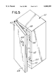
- FIG. 7 is a fragmentary top plan view of the vending machine showing the door open and the latching mechanisms extended;
- FIG. 8 is a fragmentary top plan view of the vending machine showing the door in the intermediate position and the keeper assemblies engaging the latching mechanisms;
- FIG. 9 is a fragmentary top plan view of the vending machine swing the door closed and the latching mechanisms retracted to pull the door adjacent to a front side of the vending machine;
- FIG. 10 is an enlarged partial top plan view of the lock assembly showing the keeper assemblies spaced apart from the latching mechanisms;
- FIG. 11 is an enlarged partial top plan view of the lock assembly showing the door closed, the keeper assemblies captured by the latching mechanisms, and the latching mechanisms retracted to pull the door adjacent to the front side of the vending machine;
- FIG. 12 is an enlarged perspective view of one of the latching mechanisms
- FIG. 13 is a perspective view of the latching mechanism depicted in FIG. 12 with some of the components removed for clarity;
- FIG. 14 is an inverted perspective view of the latching mechanism depicted in FIG. 13.
- FIG. 15 is a perspective view showing locking and release levers of the latching mechanism moving between locked and unlocked positions.
- an electronic lock assembly constructed in accordance with the present invention is designated generally by reference numeral 100.
- the inventive lock assembly 100 is intended for use with a vending machine 50 such as a refrigerated drink machine or the like.
- the vending machine 50 includes a plurality of side walls 52 which define a housing and a movable door 62 which is hingedly attached to one of the side walls 52 for movement between an open position, as shown, for example, in FIGS. 1, 5-7, and 10, and a closed position, as shown, for example, in FIGS. 3, 4, 9, and 11.
- the side walls 52 and the door 62 define a closed internal compartment 72 of the vending machine 50 where various products (not shown) may be conveniently stored.
- the door 62 of the vending machine 50 includes an outer face side 64 and an inner face side 66 with a gasket 68 disposed around the periphery thereof.
- the gasket 68 is substantially uniformly compressed and sealed against the edges of four side walls 52, as shown, for example, in FIG. 11.
- the gasket 68 is specifically shown attached to the inner face side 66 of the door 62, it will be readily appreciated by those skilled in the art that the gasket 68 may alternatively be attached to the edges of the four side walls 52 without departing from the scope or spirit of the present invention.
- the lock assembly 100 includes a pair of keeper assemblies 110 mounted to the inner face side 66 of the door 60 and a pair of motorized latching mechanisms 130 mounted within the internal compartment 72 of the vending machine 50.
- each keeper assembly 110 includes a support bracket 112 secured to the inner face side 66 of the door 60, and a cross-member 114 carried by the support bracket 112.
- the latching mechanisms 130 are aligned with the keeper assemblies 110 and are adapted to selectively receive and capture the cross-members 114 when the door 62 is moved from the open position towards the closed position, as indicated by reference numeral 82 in FIG. 2, and into an intermediate position. In the intermediate position, the door 62 is not quite fully closed but the keeper assemblies 110 engage the latching mechanisms 130, as shown, for example, in FIGS. 2 and 8.
- each latching mechanism 130 is slidably carried by a frame or support structure 122.
- each support structure 122 is affixed to one of the side walls 52 of the vending machine 50 by a plurality of mounting members 124.
- each support structure 122 includes a movable panel 126 which slides relative to that support structure 122 to transport the latching mechanisms 130 between an extended position, as shown in FIG. 10, and a retracted position, as shown in FIG. 11. In the extended position, the latching mechanisms 130 protrude outwardly away from the support structure 122 which allows contact between the cross-members 114 of the keeper assemblies 110 and the latching mechanisms 130 when the door 62 is in the intermediate position.
- each latching mechanism 130 comprises a rotor latch which includes a base portion 132 affixed to one of the slidable panels 126 of the support structure 122, an opposed cover portion 134, and locking and release levers 142 and 148 pivotably sandwiched between the base and cover portions 132 and 134 by pins 136.
- the locking and release levers 142 and 148 of the rotor latches 130 are selectively movable between an unlocked position, as indicated by reference numerals 142a and 148a in FIG. 15, and an locked position, as indicated by reference numerals 142b and 148b in FIG. 15.
- a biasing element 138 such as a helical coil spring or the like is coupled between the locking lever 142 and the release lever 148, as shown, for example, in FIG. 12.
- each rotor latch 130 includes a slot 139 which is sized and configured to receive one of the cross-members 114 of the keeper assemblies 110.
- the locking lever 142 of each rotor latch 130 includes a cam engagement surface 143, upper and lower engagement surfaces 144 and 145 in the form of ratchet teeth, and a hook portion 146.
- the release lever 148 includes a single ratchet tooth 149 which is adapted to selectively engage either the upper engagement surface 144 or the lower engagement surface 145 of the locking lever 142 to locate the locking and release levers 142 and 148 in the unlocked and locked positions.
- the ratchet tooth 149 of the release lever 148 engages the upper engagement surface 144 of the locking lever 142 which causes the locking and release levers 142 and 148 to assume the unlocked position indicated by reference numerals 142a and 148a, respectively, in FIG. 15.
- the hook portion 146 of the locking lever 142 is substantially free of the slot 139, as shown, for example, in FIGS. 12 and 14, which allows the cross-member 114 of one of the keeper assemblies 110 to move inwardly into the slot 139 until the cross-member 114 engages the cam engagement surface 143 of the locking lever 142.
- the lock assembly 100 is also provided with electronic circuitry, as indicated diagrammatically by reference numeral 160 in FIGS. 1-5, which, among other things, controls the location of the latching mechanisms 130 with respect to the support structures 122. More specifically, the electronic circuitry 160 selectively activates a motor (not shown) for the latching mechanisms 130 which causes the panels 126 to move inwardly or outwardly with respect to the support structures 122 between the extended and retracted positions.
- the electronic circuitry 160 of the lock assembly 100 may be provided by a single microcomputer integrated circuit, as disclosed, for example, in U.S. Pat. No. 5,617,082 which is hereby incorporated by reference in its entirety.
- the electronic circuitry 160 and the motor for latching mechanisms 130 are powered by the same external electrical supply which provides electrical current to the vending machine 50.
- a conventional wall outlet (not shown) is suitable for this purpose.
- a battery backup unit designated generally by reference numeral 170 in FIG. 1, is mounted to the vending machine 50.
- the lock assembly 100 is also provided with a remote control unit 180 with a button or activation switch 182 which causes the keeper assemblies 110 to disengage the latching mechanisms 130.
- a button 182 When this button 182 is depressed, a predetermined remote control signal 184 is provided to the electronic circuitry 160, as indicated, for example, in FIG. 4.
- the electronic circuitry 160 of the locking mechanism 100 delivers an input command or signal to the motor of latching mechanisms 130 instructing it to exert a force on the latching mechanisms 130, as indicated, for example, by reference numeral 92 in FIG. 13.
- This force 92 moves the locking and release levers 142 and 148 from the locked position toward the unlocked position and also causes the cross-members 114 of the keeper assemblies 110 to be expelled from the slots 139 of the latching mechanisms 130 as the door 62 of the vending machine 50 pivots toward the open position, as shown in FIG. 5.
- the electronic circuitry 160 delivers another input signal to the motor of the latching mechanisms 130 instructing it to move the latching mechanisms 130 from the retracted position toward the extended position, as indicated, for example, by reference numeral 94 in FIG. 6.
- the inventive lock assembly 100 operates in the following manner.
- the cam engagement surfaces 143 of the two locking levers 142 are struck by the cross-members 114 of the two keeper assemblies 110.
- This engagement between the cross-members 114 of the keeper assemblies 110 and the cam engagement surfaces 143 of the locking levers 142 causes the locking and release levers 142 and 148 to move from the unlocked position toward the locked position so as to capture the cross-members 114 within the slots 139 of the latching mechanisms 130 and against the hook portions 146 of the locking levers 142, as shown in FIG. 15.
- the electronic circuitry 160 delivers a signal to the motor of the latching mechanisms 130 instructing it to transport the latching mechanisms 130 from the extended position toward the retracted position so as to draw the door 62 into the closed position, as shown in FIGS. 3 and 9, until the gasket 68 is substantially uniformly compressed and sealed against the edges of the side walls 52 of the vending machine 50.
- the door 62 remains in the closed position until the button or switch 182 of the remote control unit 180 is depressed or otherwise activated, as shown, for example, in FIG. 4.
- remote control signal 184 is transmitted to the electronic circuitry 160 of the lock assembly 100 which causes the electronic circuitry 160 to deliver an electronic signal to the motor of the latching mechanisms 130 instructing it to exert force 92 on the latching mechanisms 130.
- This electronic signal causes the locking and release levers 142 and 148 to move from the locked position toward the unlocked position which, in turn, causes the cross-members 114 of the keeper assemblies 110 to be expelled from the slots 139 of the latching mechanisms 130 as the door 62 pivots toward the open position, as shown in FIG. 5.
- the vending machine 50 may be conveniently serviced.
- the electronic circuitry 160 delivers a subsequent signal to the motor of the latching mechanisms 130 instructing it to transport the latching mechanisms 130 from the retracted position toward the extended position, as shown in FIG. 6, so as to properly locate the latching mechanisms 130 for the next cycle of operation.
Abstract
Description
Claims (19)
Priority Applications (1)
| Application Number | Priority Date | Filing Date | Title |
|---|---|---|---|
| US09/112,027 US6068305A (en) | 1997-07-09 | 1998-07-08 | Lock assembly for vending machines and method for locking and unlocking same |
Applications Claiming Priority (2)
| Application Number | Priority Date | Filing Date | Title |
|---|---|---|---|
| US5206497P | 1997-07-09 | 1997-07-09 | |
| US09/112,027 US6068305A (en) | 1997-07-09 | 1998-07-08 | Lock assembly for vending machines and method for locking and unlocking same |
Publications (1)
| Publication Number | Publication Date |
|---|---|
| US6068305A true US6068305A (en) | 2000-05-30 |
Family
ID=26730126
Family Applications (1)
| Application Number | Title | Priority Date | Filing Date |
|---|---|---|---|
| US09/112,027 Expired - Fee Related US6068305A (en) | 1997-07-09 | 1998-07-08 | Lock assembly for vending machines and method for locking and unlocking same |
Country Status (1)
| Country | Link |
|---|---|
| US (1) | US6068305A (en) |
Cited By (70)
| Publication number | Priority date | Publication date | Assignee | Title |
|---|---|---|---|---|
| US20010042121A1 (en) * | 2000-05-12 | 2001-11-15 | Isochron Data Corporation | Method and system for the optimal formating, reduction and compression of DEX/UCS data |
| US20010054083A1 (en) * | 1998-03-19 | 2001-12-20 | Isochron Data Corporation | System and method for monitoring and control of beverage dispensing equipment |
| US20020014950A1 (en) * | 1998-08-12 | 2002-02-07 | Ayala Raymond F. | Method for programming a key for selectively allowing access to an enclosure |
| US20020016829A1 (en) * | 1998-03-19 | 2002-02-07 | Isochron Data Corporation | Remote data acquisition, transmission and analysis system including handheld wireless equipment |
| US20020024418A1 (en) * | 1999-08-11 | 2002-02-28 | Ayala Raymond F. | Method for a key to selectively allow access to an enclosure |
| US20020024420A1 (en) * | 1998-08-12 | 2002-02-28 | Ayala Raymond F. | Key for selectively allowing access to an enclosure |
| US6374649B1 (en) * | 1999-02-04 | 2002-04-23 | Waterloo Industries, Inc. | Electronic remote entry lock system for a tool cabinet |
| US20020147525A1 (en) * | 2000-06-30 | 2002-10-10 | Jordan Cayne | Intelligent locking system |
| US6496101B1 (en) * | 1998-08-12 | 2002-12-17 | Star Lock Systems, Inc. | Electro-mechanical latch assembly |
| US20030003865A1 (en) * | 2001-06-29 | 2003-01-02 | Defosse Erin M. | Method and system for interfacing a machine controller and a wireless network |
| US20030009313A1 (en) * | 2001-07-05 | 2003-01-09 | Isochron Data Corporation | Real-time alert mechanism for monitoring and controlling field assets via wireless and internet technologies |
| US6525644B1 (en) * | 1998-08-12 | 2003-02-25 | Star Lock Systems, Inc. | Electro-mechanical latch assembly |
| US20030101262A1 (en) * | 2001-11-27 | 2003-05-29 | Isochron Data Corporation | Method and system for scheduling the maintenance of remotely monitored devices |
| US20030101257A1 (en) * | 2001-11-27 | 2003-05-29 | Isochron Data Corporation | Method and system for predicting the services needs of remote point of sale devices |
| US6575504B2 (en) * | 2000-11-21 | 2003-06-10 | Triteq Lock And Security, L.L.C. | Bayonet locking system and method for vending machines and the like |
| US6581986B2 (en) * | 2000-11-21 | 2003-06-24 | Tri Teq Lock And Security, L.L.C. | Bayonet locking system and method for vending machines and the like |
| US20030127866A1 (en) * | 2001-12-14 | 2003-07-10 | Martinez Richard A. | Electromechanical locking mechanism |
| US20030204391A1 (en) * | 2002-04-30 | 2003-10-30 | Isochron Data Corporation | Method and system for interpreting information communicated in disparate dialects |
| US20030205953A1 (en) * | 2002-05-01 | 2003-11-06 | Fox Robert N. | Electromagnetic locking system for cabinet doors and drawers |
| US20030213280A1 (en) * | 2002-03-05 | 2003-11-20 | Stresswave, Inc. | Control devices for cold-working structures |
| US20040000205A1 (en) * | 2002-04-14 | 2004-01-01 | Hitesh Cherry | Electromechanical latching system |
| US20040050218A1 (en) * | 2002-07-01 | 2004-03-18 | Frederick Napoli | Tool for turning a T-Handle lock assembly |
| US20040133653A1 (en) * | 1998-03-19 | 2004-07-08 | Cac Vending Systems, L.L.C. | System, method and apparatus for vending machine wireless audit and cashless transaction transport |
| US20040154363A1 (en) * | 2000-11-02 | 2004-08-12 | Beylotte James E. | Vending machine lock |
| US20040178885A1 (en) * | 1994-11-15 | 2004-09-16 | Denison William D. | Electronic access control device |
| US20040227349A1 (en) * | 2003-05-13 | 2004-11-18 | Andre Denys | Multi-point lock assembly |
| US20050088279A1 (en) * | 2001-12-27 | 2005-04-28 | Micro Enhanced Technology, Inc. | Vending machines with field-programmable electronic locks |
| US20050184857A1 (en) * | 2003-12-11 | 2005-08-25 | Triteq Lock And Security, Llc | Electronic security apparatus and method for monitoring mechanical keys and other items |
| US20050193932A1 (en) * | 2004-03-05 | 2005-09-08 | Triteq Lock And Security, L.L.C. | Safe lock with motor controlled bolts and electronic access |
| US7010594B2 (en) | 2000-05-26 | 2006-03-07 | Isochron, Llc | System using environmental sensor and intelligent management and control transceiver for monitoring and controlling remote computing resources |
| US7040675B1 (en) | 2003-02-12 | 2006-05-09 | The Eastern Company | Linkage operated latching system |
| US20060161473A1 (en) * | 1998-03-19 | 2006-07-20 | Defosse Erin M | Remote data acquisition, transmission and analysis system including handheld wireless equipment |
| US20060179900A1 (en) * | 2004-03-05 | 2006-08-17 | Triteq Lock And Security, L.L.C. | Vending machine lock with motor controlled slide-bar and hook mechanism and electronic access |
| US20060244415A1 (en) * | 2003-11-18 | 2006-11-02 | Denison William D | Battery back-up for vending machine lock |
| US20070024062A1 (en) * | 2003-09-11 | 2007-02-01 | Compeau David E | Vending machine lock |
| US20070050465A1 (en) * | 1998-03-19 | 2007-03-01 | Canter James M | Packet capture agent for use in field assets employing shared bus architecture |
| US20070053519A1 (en) * | 2005-08-30 | 2007-03-08 | Godwin Bryan W | Wireless adapter for data exchange and method |
| US20070072548A1 (en) * | 2001-06-29 | 2007-03-29 | Godwin Bryan W | Apparatus and Method to Provide Multiple Wireless Communication Paths to and from Remotely Located Equipment |
| US20070085348A1 (en) * | 2003-10-17 | 2007-04-19 | Nye-Hingston Matthew R A | A Cabinet Lock |
| US20070090920A1 (en) * | 2005-10-22 | 2007-04-26 | Canter James M | Apparatus and Method for Controlling Access to Remotely Located Equipment |
| US20070096867A1 (en) * | 2001-12-27 | 2007-05-03 | Denison William D | Vending machines with field-programmable electronic locks |
| US20070195490A1 (en) * | 2006-02-13 | 2007-08-23 | Howell Sean V | Apparatus And Method For Attaching An Electronic Module To A Lock Assembly |
| US20080067818A1 (en) * | 2006-08-09 | 2008-03-20 | Hartwell Corporation | Bifurcated latching system |
| US20080083770A1 (en) * | 2006-09-13 | 2008-04-10 | Godwin Bryan W | Rich content management and display for use in remote field assets |
| US7373352B2 (en) | 2003-12-11 | 2008-05-13 | Triteq Lock And Security, Llc | Electronic key-control and management system for vending machines |
| US20080129056A1 (en) * | 2006-11-30 | 2008-06-05 | Hartwell Corporation | Command Latch and Pin Latch System |
| US20080231154A1 (en) * | 2005-01-20 | 2008-09-25 | Telezygology, Inc. | Locking Systems |
| US20090013028A1 (en) * | 2007-07-02 | 2009-01-08 | Canter James M | Apparatus And Method For Monitoring And Control Of Remotely Located Equipment |
| US20090051486A1 (en) * | 2001-12-27 | 2009-02-26 | Micro Enhanced Technologies, Inc | Electronic key control and management system for vending machines and the like |
| US20090113038A1 (en) * | 2007-10-25 | 2009-04-30 | Godwin Bryan W | Systems and Methods for Monitoring Performance of Field Assets |
| US20100264677A1 (en) * | 2000-11-21 | 2010-10-21 | Denison William D | Electronic Locking Systems for Vending Machines and the Like |
| US7821395B2 (en) | 2001-12-27 | 2010-10-26 | Micro Enhanced Technology, Inc. | Vending machines with field-programmable locks |
| US20110084506A1 (en) * | 2000-11-21 | 2011-04-14 | Calin Roatis | Locking System with Retractable Hook |
| WO2011146960A1 (en) * | 2010-05-27 | 2011-12-01 | Gainsborough Hardware Industries Limited | A power source and/or control component housing primarily for door mounted devices |
| US20110302847A1 (en) * | 2010-06-15 | 2011-12-15 | Eaton Corporation | Adjustable lock body assembly |
| US20120293655A1 (en) * | 2011-05-19 | 2012-11-22 | Stanton Concepts, L.L.C. | Vertical Rod Engaging Latch Lock |
| US8484068B2 (en) | 2005-12-14 | 2013-07-09 | Crane Merchandising Systems, Inc. | Method and system for evaluating consumer demand for multiple products and services at remotely located equipment |
| US8631093B2 (en) | 1998-03-19 | 2014-01-14 | Crane Merchandising Systems, Inc. | Remote data acquisition, transmission and analysis system including handheld wireless equipment |
| USD745580S1 (en) | 2014-09-10 | 2015-12-15 | Leer, Inc. | Merchandiser |
| USD775882S1 (en) | 2014-10-24 | 2017-01-10 | Leer, Inc. | Merchandiser |
| USD783063S1 (en) | 2014-10-24 | 2017-04-04 | Leer, Inc. | Door with handle for merchandiser |
| USD789714S1 (en) | 2014-10-24 | 2017-06-20 | Leer, Inc. | Merchandiser |
| US10206525B2 (en) | 2014-10-24 | 2019-02-19 | Leer, Inc. | Ice merchandiser with on-product financial payment system |
| US10269202B2 (en) | 2001-12-27 | 2019-04-23 | Mobile Tech, Inc. | Intelligent key system |
| US10273715B2 (en) | 2013-05-15 | 2019-04-30 | Triteq Lock And Security Llc | Lock |
| US10540872B2 (en) | 2016-04-15 | 2020-01-21 | Mobile Tech, Inc. | Gateway-based anti-theft security system and method |
| US10914098B2 (en) | 2019-05-30 | 2021-02-09 | Digilock Asia Ltd. | Enclosure latch system |
| US11002039B2 (en) | 2012-04-20 | 2021-05-11 | Triteq Lock And Security, L.L.C. | Electronic controlled handles |
| US11325309B2 (en) * | 2019-08-23 | 2022-05-10 | Layerwise Nv | Three-dimensional printing system with improved process chamber |
| US11492834B2 (en) * | 2019-02-25 | 2022-11-08 | Amoskeag Adv Llc | Apparatus, system and method for powered doors of an autonomous delivery vehicle |
Citations (15)
| Publication number | Priority date | Publication date | Assignee | Title |
|---|---|---|---|---|
| US3089330A (en) * | 1961-12-07 | 1963-05-14 | Chicago Lock Co | Lock assembly for a refrigerated cabinet or the like |
| US3550412A (en) * | 1968-04-16 | 1970-12-29 | Automatic Merchandising Mach | Door lock |
| US4268076A (en) * | 1977-09-27 | 1981-05-19 | Kabushiki Kaisha Itoi Seisakusho | Cash box provided with a till |
| US4552001A (en) * | 1983-12-06 | 1985-11-12 | Medeco Security Locks, Inc. | High security T-handle assembly |
| US4685316A (en) * | 1986-03-24 | 1987-08-11 | Hicks Harry H | Window guard latch with emergency release |
| US4760721A (en) * | 1986-01-27 | 1988-08-02 | Chicago Lock Company | Handle flange assembly |
| US4802350A (en) * | 1987-04-29 | 1989-02-07 | Rockwell-Cim | Assembly of a door latch and anti-theft and anti-attack deactivating device for said latch, and latch which is part of said assembly |
| US4899561A (en) * | 1989-04-10 | 1990-02-13 | Fort Lock Corporation | Pop-out handle lock assembly |
| US4906035A (en) * | 1987-12-02 | 1990-03-06 | Fuji Jukogyo Kabushiki Kaisha | Automatic locking device for trunk lid of motor vehicle |
| US5351512A (en) * | 1993-07-20 | 1994-10-04 | Reading Body Works | Dual mode locking system for truck service bodies |
| US5507161A (en) * | 1992-12-22 | 1996-04-16 | Samsonite Corporation | Device for locking a closure mechanism for luggage |
| US5548982A (en) * | 1994-07-19 | 1996-08-27 | Rawling; James | Security bolt for T-handle assembly with retrofit capability |
| US5575515A (en) * | 1994-02-10 | 1996-11-19 | Fuji Electric Co., Ltd. | Door locking apparatus for dispenser |
| US5762384A (en) * | 1995-10-26 | 1998-06-09 | Kiekert Ag | Vehicle door lock with a centrally-operated locking unit |
| US5832757A (en) * | 1996-08-27 | 1998-11-10 | Mitsui Kinzoku Kogyo Kabushiki Kaisha | Latch device for a vehicle |
-
1998
- 1998-07-08 US US09/112,027 patent/US6068305A/en not_active Expired - Fee Related
Patent Citations (15)
| Publication number | Priority date | Publication date | Assignee | Title |
|---|---|---|---|---|
| US3089330A (en) * | 1961-12-07 | 1963-05-14 | Chicago Lock Co | Lock assembly for a refrigerated cabinet or the like |
| US3550412A (en) * | 1968-04-16 | 1970-12-29 | Automatic Merchandising Mach | Door lock |
| US4268076A (en) * | 1977-09-27 | 1981-05-19 | Kabushiki Kaisha Itoi Seisakusho | Cash box provided with a till |
| US4552001A (en) * | 1983-12-06 | 1985-11-12 | Medeco Security Locks, Inc. | High security T-handle assembly |
| US4760721A (en) * | 1986-01-27 | 1988-08-02 | Chicago Lock Company | Handle flange assembly |
| US4685316A (en) * | 1986-03-24 | 1987-08-11 | Hicks Harry H | Window guard latch with emergency release |
| US4802350A (en) * | 1987-04-29 | 1989-02-07 | Rockwell-Cim | Assembly of a door latch and anti-theft and anti-attack deactivating device for said latch, and latch which is part of said assembly |
| US4906035A (en) * | 1987-12-02 | 1990-03-06 | Fuji Jukogyo Kabushiki Kaisha | Automatic locking device for trunk lid of motor vehicle |
| US4899561A (en) * | 1989-04-10 | 1990-02-13 | Fort Lock Corporation | Pop-out handle lock assembly |
| US5507161A (en) * | 1992-12-22 | 1996-04-16 | Samsonite Corporation | Device for locking a closure mechanism for luggage |
| US5351512A (en) * | 1993-07-20 | 1994-10-04 | Reading Body Works | Dual mode locking system for truck service bodies |
| US5575515A (en) * | 1994-02-10 | 1996-11-19 | Fuji Electric Co., Ltd. | Door locking apparatus for dispenser |
| US5548982A (en) * | 1994-07-19 | 1996-08-27 | Rawling; James | Security bolt for T-handle assembly with retrofit capability |
| US5762384A (en) * | 1995-10-26 | 1998-06-09 | Kiekert Ag | Vehicle door lock with a centrally-operated locking unit |
| US5832757A (en) * | 1996-08-27 | 1998-11-10 | Mitsui Kinzoku Kogyo Kabushiki Kaisha | Latch device for a vehicle |
Cited By (125)
| Publication number | Priority date | Publication date | Assignee | Title |
|---|---|---|---|---|
| US7741952B2 (en) | 1994-11-15 | 2010-06-22 | Micro Enhanced Technology, Inc. | Electronic access control device |
| US20040178885A1 (en) * | 1994-11-15 | 2004-09-16 | Denison William D. | Electronic access control device |
| US7683758B2 (en) | 1994-11-15 | 2010-03-23 | Denison William D | Electronic access control device |
| US20050212656A1 (en) * | 1994-11-15 | 2005-09-29 | Micro Enhanced Technology, Inc. | Electronic access control device |
| US20070164324A1 (en) * | 1994-11-15 | 2007-07-19 | Denison William D | Electronic access control device |
| US8587405B2 (en) | 1994-11-15 | 2013-11-19 | O.S. Security | Electronic access control device |
| US20070083287A1 (en) * | 1998-03-19 | 2007-04-12 | Defosse Erin M | System, Method And Apparatus For Vending Machine Wireless Audit And Cashless Transaction Transport |
| US20060161473A1 (en) * | 1998-03-19 | 2006-07-20 | Defosse Erin M | Remote data acquisition, transmission and analysis system including handheld wireless equipment |
| US7167892B2 (en) * | 1998-03-19 | 2007-01-23 | Isochron, Inc. | System, method and apparatus for vending machine wireless audit and cashless transaction transport |
| US7181501B2 (en) | 1998-03-19 | 2007-02-20 | Isochron, Inc. | Remote data acquisition, transmission and analysis system including handheld wireless equipment |
| US7020680B2 (en) | 1998-03-19 | 2006-03-28 | Isochron, Llc | System and method for monitoring and control of beverage dispensing equipment |
| US20070050465A1 (en) * | 1998-03-19 | 2007-03-01 | Canter James M | Packet capture agent for use in field assets employing shared bus architecture |
| US20020016829A1 (en) * | 1998-03-19 | 2002-02-07 | Isochron Data Corporation | Remote data acquisition, transmission and analysis system including handheld wireless equipment |
| US20040133653A1 (en) * | 1998-03-19 | 2004-07-08 | Cac Vending Systems, L.L.C. | System, method and apparatus for vending machine wireless audit and cashless transaction transport |
| US8631093B2 (en) | 1998-03-19 | 2014-01-14 | Crane Merchandising Systems, Inc. | Remote data acquisition, transmission and analysis system including handheld wireless equipment |
| US20010054083A1 (en) * | 1998-03-19 | 2001-12-20 | Isochron Data Corporation | System and method for monitoring and control of beverage dispensing equipment |
| US20020024420A1 (en) * | 1998-08-12 | 2002-02-28 | Ayala Raymond F. | Key for selectively allowing access to an enclosure |
| US20020014950A1 (en) * | 1998-08-12 | 2002-02-07 | Ayala Raymond F. | Method for programming a key for selectively allowing access to an enclosure |
| US6525644B1 (en) * | 1998-08-12 | 2003-02-25 | Star Lock Systems, Inc. | Electro-mechanical latch assembly |
| US6496101B1 (en) * | 1998-08-12 | 2002-12-17 | Star Lock Systems, Inc. | Electro-mechanical latch assembly |
| US6374649B1 (en) * | 1999-02-04 | 2002-04-23 | Waterloo Industries, Inc. | Electronic remote entry lock system for a tool cabinet |
| US20020024418A1 (en) * | 1999-08-11 | 2002-02-28 | Ayala Raymond F. | Method for a key to selectively allow access to an enclosure |
| US20010042121A1 (en) * | 2000-05-12 | 2001-11-15 | Isochron Data Corporation | Method and system for the optimal formating, reduction and compression of DEX/UCS data |
| US7013337B2 (en) | 2000-05-12 | 2006-03-14 | Isochron, Llc | Method and system for the optimal formatting, reduction and compression of DEX/UCS data |
| US7010594B2 (en) | 2000-05-26 | 2006-03-07 | Isochron, Llc | System using environmental sensor and intelligent management and control transceiver for monitoring and controlling remote computing resources |
| US20060267727A1 (en) * | 2000-06-30 | 2006-11-30 | Jordan Cayne | Intelligent locking system using biometrics |
| US20060255905A1 (en) * | 2000-06-30 | 2006-11-16 | Jordan Cayne | Methods of using an intelligent locking system |
| US6806807B2 (en) * | 2000-06-30 | 2004-10-19 | Jordan Cayne | Intelligent locking system |
| US7113071B2 (en) | 2000-06-30 | 2006-09-26 | Jordan Cayne | Intelligent locking system |
| US20050040932A1 (en) * | 2000-06-30 | 2005-02-24 | Jordan Cayne | Intelligent locking system |
| US20020147525A1 (en) * | 2000-06-30 | 2002-10-10 | Jordan Cayne | Intelligent locking system |
| US7760069B2 (en) | 2000-06-30 | 2010-07-20 | Typhoon Industries Llc | Methods of using an intelligent locking system |
| US7191624B2 (en) | 2000-11-02 | 2007-03-20 | Stanley Security Solutions, Inc. | Vending machine lock |
| US20040154363A1 (en) * | 2000-11-02 | 2004-08-12 | Beylotte James E. | Vending machine lock |
| US6874828B2 (en) | 2000-11-21 | 2005-04-05 | Triteq Lock And Security, L.L.C. | Bayonet locking system for vending machines and the like |
| US6575504B2 (en) * | 2000-11-21 | 2003-06-10 | Triteq Lock And Security, L.L.C. | Bayonet locking system and method for vending machines and the like |
| US9260886B2 (en) * | 2000-11-21 | 2016-02-16 | Triteq Lock And Security, Llc | Electronic cam locking systems for vending machines and the like |
| US9523215B2 (en) * | 2000-11-21 | 2016-12-20 | Triteq Lock And Security, Llc | Electronic locking systems for vending machines and the like |
| US20050161953A1 (en) * | 2000-11-21 | 2005-07-28 | Triteq Lock & Security, Llc. | Bayonet locking system for vending machines and the like |
| US6581986B2 (en) * | 2000-11-21 | 2003-06-24 | Tri Teq Lock And Security, L.L.C. | Bayonet locking system and method for vending machines and the like |
| US20100264677A1 (en) * | 2000-11-21 | 2010-10-21 | Denison William D | Electronic Locking Systems for Vending Machines and the Like |
| US20110084506A1 (en) * | 2000-11-21 | 2011-04-14 | Calin Roatis | Locking System with Retractable Hook |
| US20060186678A1 (en) * | 2000-11-21 | 2006-08-24 | Triteq Lock And Security, Llc | Electronic cam locking systems for vending machines and the like |
| US7778600B2 (en) | 2001-06-29 | 2010-08-17 | Crane Merchandising Systems, Inc. | Apparatus and method to provide multiple wireless communication paths to and from remotely located equipment |
| US7164884B2 (en) | 2001-06-29 | 2007-01-16 | Isochron, Llc | Method and system for interfacing a machine controller and a wireless network |
| US20060183422A1 (en) * | 2001-06-29 | 2006-08-17 | Defosse Erin M | Method and System for Interfacing a Machine Controller and a Wireless Network |
| US20030003865A1 (en) * | 2001-06-29 | 2003-01-02 | Defosse Erin M. | Method and system for interfacing a machine controller and a wireless network |
| US20070072548A1 (en) * | 2001-06-29 | 2007-03-29 | Godwin Bryan W | Apparatus and Method to Provide Multiple Wireless Communication Paths to and from Remotely Located Equipment |
| US8005425B2 (en) | 2001-06-29 | 2011-08-23 | Crane Merchandising Systems, Inc. | Method and system for interfacing a machine controller and a wireless network |
| US6925335B2 (en) | 2001-07-05 | 2005-08-02 | Isochron, Llc | Real-time alert mechanism for monitoring and controlling field assets via wireless and internet technologies |
| US20030009313A1 (en) * | 2001-07-05 | 2003-01-09 | Isochron Data Corporation | Real-time alert mechanism for monitoring and controlling field assets via wireless and internet technologies |
| US20050192678A1 (en) * | 2001-07-05 | 2005-09-01 | May James A. | Real-time alert mechanism for monitoring and controlling field assets via wireless and internet technologies |
| US7139616B2 (en) | 2001-07-05 | 2006-11-21 | Isochron, Llc | Real-time alert mechanism for monitoring and controlling field assets via wireless and internet technologies |
| US20030101262A1 (en) * | 2001-11-27 | 2003-05-29 | Isochron Data Corporation | Method and system for scheduling the maintenance of remotely monitored devices |
| US20030101257A1 (en) * | 2001-11-27 | 2003-05-29 | Isochron Data Corporation | Method and system for predicting the services needs of remote point of sale devices |
| US7523182B2 (en) | 2001-11-27 | 2009-04-21 | Isochron, Inc. | Method and system for predicting the services needs of remote point of sale devices |
| US6886869B2 (en) * | 2001-12-14 | 2005-05-03 | Richard A. Martinez | Electromechanical locking mechanism |
| US20030127866A1 (en) * | 2001-12-14 | 2003-07-10 | Martinez Richard A. | Electromechanical locking mechanism |
| US20070096867A1 (en) * | 2001-12-27 | 2007-05-03 | Denison William D | Vending machines with field-programmable electronic locks |
| US10984625B2 (en) | 2001-12-27 | 2021-04-20 | Mobile Tech, Inc. | Intelligent key system |
| US10269202B2 (en) | 2001-12-27 | 2019-04-23 | Mobile Tech, Inc. | Intelligent key system |
| US7821395B2 (en) | 2001-12-27 | 2010-10-26 | Micro Enhanced Technology, Inc. | Vending machines with field-programmable locks |
| US20090051486A1 (en) * | 2001-12-27 | 2009-02-26 | Micro Enhanced Technologies, Inc | Electronic key control and management system for vending machines and the like |
| US7495543B2 (en) | 2001-12-27 | 2009-02-24 | Micro Enhanced Technology, Inc. | Vending machines with field-programmable electronic locks |
| US10453291B2 (en) | 2001-12-27 | 2019-10-22 | Mobile Tech, Inc. | Intelligent key system |
| US20070096866A1 (en) * | 2001-12-27 | 2007-05-03 | Denison William D | Vending machines with field-programmable electronic locks |
| US20050088279A1 (en) * | 2001-12-27 | 2005-04-28 | Micro Enhanced Technology, Inc. | Vending machines with field-programmable electronic locks |
| US20030213280A1 (en) * | 2002-03-05 | 2003-11-20 | Stresswave, Inc. | Control devices for cold-working structures |
| US7073827B2 (en) | 2002-04-14 | 2006-07-11 | Southco, Inc. | Electromechanical latching system |
| US20040000205A1 (en) * | 2002-04-14 | 2004-01-01 | Hitesh Cherry | Electromechanical latching system |
| US20030204391A1 (en) * | 2002-04-30 | 2003-10-30 | Isochron Data Corporation | Method and system for interpreting information communicated in disparate dialects |
| US20030205953A1 (en) * | 2002-05-01 | 2003-11-06 | Fox Robert N. | Electromagnetic locking system for cabinet doors and drawers |
| US20040050218A1 (en) * | 2002-07-01 | 2004-03-18 | Frederick Napoli | Tool for turning a T-Handle lock assembly |
| US7040675B1 (en) | 2003-02-12 | 2006-05-09 | The Eastern Company | Linkage operated latching system |
| US6981724B2 (en) | 2003-05-13 | 2006-01-03 | Fasco Die Cast, Inc. | Multi-point lock assembly |
| US20040227349A1 (en) * | 2003-05-13 | 2004-11-18 | Andre Denys | Multi-point lock assembly |
| US7823936B2 (en) * | 2003-09-11 | 2010-11-02 | Stanley Security Solutions, Inc. | Vending machine lock |
| US20070024062A1 (en) * | 2003-09-11 | 2007-02-01 | Compeau David E | Vending machine lock |
| US20070085348A1 (en) * | 2003-10-17 | 2007-04-19 | Nye-Hingston Matthew R A | A Cabinet Lock |
| US7445255B2 (en) * | 2003-10-17 | 2008-11-04 | Magna Limited | Cabinet lock |
| US20060244415A1 (en) * | 2003-11-18 | 2006-11-02 | Denison William D | Battery back-up for vending machine lock |
| US7373352B2 (en) | 2003-12-11 | 2008-05-13 | Triteq Lock And Security, Llc | Electronic key-control and management system for vending machines |
| US8643487B2 (en) | 2003-12-11 | 2014-02-04 | Triteq Lock And Security, Llc | Electronic security system for monitoring mechanical keys and other items |
| US20050184857A1 (en) * | 2003-12-11 | 2005-08-25 | Triteq Lock And Security, Llc | Electronic security apparatus and method for monitoring mechanical keys and other items |
| US8876172B2 (en) | 2004-03-05 | 2014-11-04 | Triteq Lock And Security, Llc | Vending machine lock with motor controlled slide-bar and hook mechanism and electronic access |
| US10174522B2 (en) * | 2004-03-05 | 2019-01-08 | Triteq Lock And Security, L.L.C. | Vending machine lock with motor controlled slide-bar and hook mechanism and electronic access |
| US20150069765A1 (en) * | 2004-03-05 | 2015-03-12 | Triteq Lock And Security, L.L.C. | Vending Machine Lock with Motor Controlled Slide-Bar and Hook Mechanism and Electronic Access |
| US20050193932A1 (en) * | 2004-03-05 | 2005-09-08 | Triteq Lock And Security, L.L.C. | Safe lock with motor controlled bolts and electronic access |
| US20060179900A1 (en) * | 2004-03-05 | 2006-08-17 | Triteq Lock And Security, L.L.C. | Vending machine lock with motor controlled slide-bar and hook mechanism and electronic access |
| US20080231154A1 (en) * | 2005-01-20 | 2008-09-25 | Telezygology, Inc. | Locking Systems |
| US20070053519A1 (en) * | 2005-08-30 | 2007-03-08 | Godwin Bryan W | Wireless adapter for data exchange and method |
| US20070090920A1 (en) * | 2005-10-22 | 2007-04-26 | Canter James M | Apparatus and Method for Controlling Access to Remotely Located Equipment |
| US8484068B2 (en) | 2005-12-14 | 2013-07-09 | Crane Merchandising Systems, Inc. | Method and system for evaluating consumer demand for multiple products and services at remotely located equipment |
| US20070195490A1 (en) * | 2006-02-13 | 2007-08-23 | Howell Sean V | Apparatus And Method For Attaching An Electronic Module To A Lock Assembly |
| US8016327B2 (en) * | 2006-08-09 | 2011-09-13 | Hartwell Corporation | Bifurcated latching system |
| US20080067818A1 (en) * | 2006-08-09 | 2008-03-20 | Hartwell Corporation | Bifurcated latching system |
| US20080083770A1 (en) * | 2006-09-13 | 2008-04-10 | Godwin Bryan W | Rich content management and display for use in remote field assets |
| US7997484B2 (en) | 2006-09-13 | 2011-08-16 | Crane Merchandising Systems, Inc. | Rich content management and display for use in remote field assets |
| US20080129056A1 (en) * | 2006-11-30 | 2008-06-05 | Hartwell Corporation | Command Latch and Pin Latch System |
| US8925979B2 (en) | 2006-11-30 | 2015-01-06 | Hartwell Corporation | Command latch and pin latch system |
| US20090013028A1 (en) * | 2007-07-02 | 2009-01-08 | Canter James M | Apparatus And Method For Monitoring And Control Of Remotely Located Equipment |
| US8959028B2 (en) | 2007-07-02 | 2015-02-17 | Crane Merchandising Systems, Inc. | Apparatus and method for monitoring and control of remotely located equipment |
| US20090113038A1 (en) * | 2007-10-25 | 2009-04-30 | Godwin Bryan W | Systems and Methods for Monitoring Performance of Field Assets |
| US8533315B2 (en) | 2007-10-25 | 2013-09-10 | Crane Merchandising Systems, Inc. | Systems and methods for monitoring performance of field assets |
| AU2011257943B2 (en) * | 2010-05-27 | 2015-05-14 | Allegion (Australia) Pty Ltd | A power source and/or control component housing primarily for door mounted devices |
| WO2011146960A1 (en) * | 2010-05-27 | 2011-12-01 | Gainsborough Hardware Industries Limited | A power source and/or control component housing primarily for door mounted devices |
| US20110302847A1 (en) * | 2010-06-15 | 2011-12-15 | Eaton Corporation | Adjustable lock body assembly |
| US20120293655A1 (en) * | 2011-05-19 | 2012-11-22 | Stanton Concepts, L.L.C. | Vertical Rod Engaging Latch Lock |
| US11002039B2 (en) | 2012-04-20 | 2021-05-11 | Triteq Lock And Security, L.L.C. | Electronic controlled handles |
| US10273715B2 (en) | 2013-05-15 | 2019-04-30 | Triteq Lock And Security Llc | Lock |
| USD745580S1 (en) | 2014-09-10 | 2015-12-15 | Leer, Inc. | Merchandiser |
| US11076710B2 (en) | 2014-10-24 | 2021-08-03 | Leer, Inc. | Merchandiser with on-product financial payment system |
| USD783063S1 (en) | 2014-10-24 | 2017-04-04 | Leer, Inc. | Door with handle for merchandiser |
| US11419435B2 (en) | 2014-10-24 | 2022-08-23 | Leer, Inc. | Merchandiser with sensing capabilities |
| US10674841B2 (en) | 2014-10-24 | 2020-06-09 | Leer, Inc. | Merchandiser with on-product financial payment system |
| US10206525B2 (en) | 2014-10-24 | 2019-02-19 | Leer, Inc. | Ice merchandiser with on-product financial payment system |
| US10849442B2 (en) | 2014-10-24 | 2020-12-01 | Leer, Inc. | Ice merchandiser with sensing capabilities |
| USD775882S1 (en) | 2014-10-24 | 2017-01-10 | Leer, Inc. | Merchandiser |
| USD789714S1 (en) | 2014-10-24 | 2017-06-20 | Leer, Inc. | Merchandiser |
| US10776473B2 (en) | 2016-04-15 | 2020-09-15 | Mobile Tech, Inc. | Authorization control for an anti-theft security system |
| US11315398B2 (en) | 2016-04-15 | 2022-04-26 | Mobile Tech, Inc. | Gateway-based anti-theft security system and method |
| US10540872B2 (en) | 2016-04-15 | 2020-01-21 | Mobile Tech, Inc. | Gateway-based anti-theft security system and method |
| US11492834B2 (en) * | 2019-02-25 | 2022-11-08 | Amoskeag Adv Llc | Apparatus, system and method for powered doors of an autonomous delivery vehicle |
| US10914098B2 (en) | 2019-05-30 | 2021-02-09 | Digilock Asia Ltd. | Enclosure latch system |
| US11325309B2 (en) * | 2019-08-23 | 2022-05-10 | Layerwise Nv | Three-dimensional printing system with improved process chamber |
Similar Documents
| Publication | Publication Date | Title |
|---|---|---|
| US6068305A (en) | Lock assembly for vending machines and method for locking and unlocking same | |
| US6053543A (en) | Vehicle door latch | |
| US6019402A (en) | Vehicle door latch with double lock | |
| US4125008A (en) | Electrically operated lock | |
| US8146394B2 (en) | Rotary lock actuator | |
| US20110084506A1 (en) | Locking System with Retractable Hook | |
| US20060186678A1 (en) | Electronic cam locking systems for vending machines and the like | |
| KR20030038657A (en) | Electrically operated ratcheting pawl latch | |
| CA2103310A1 (en) | Latching apparatus for double doors | |
| CA1319940C (en) | Automotive door locking apparatus | |
| US20010010166A1 (en) | Override mechanism for unlatching an electronic door lock | |
| JPH01247677A (en) | Locking device for vehicle door | |
| US3543546A (en) | Automobile door safety lock | |
| JPH01192979A (en) | Automatic switchgear for door | |
| JP2577897Y2 (en) | Locking and unlocking device for vehicles | |
| JP2733830B2 (en) | Door lock handle device | |
| JP2747407B2 (en) | Delivery box switchgear | |
| JPS6140860Y2 (en) | ||
| KR20130027685A (en) | Electronic rotary latch | |
| JP3126750B2 (en) | Door handle device | |
| JP3769154B2 (en) | Door lock device | |
| JPH0546624Y2 (en) | ||
| JPH0327181Y2 (en) | ||
| KR200268503Y1 (en) | door lock up apparatus | |
| JPH041254Y2 (en) |
Legal Events
| Date | Code | Title | Description |
|---|---|---|---|
| AS | Assignment |
Owner name: FORT LOCK CORPORATION, ILLINOIS Free format text: ASSIGNMENT OF ASSIGNORS INTEREST;ASSIGNORS:MYERS, GARY L.;DENISON, WILLIAM D.;CAPLINGER, PAUL D.;AND OTHERS;REEL/FRAME:009573/0570 Effective date: 19980702 |
|
| AS | Assignment |
Owner name: COMPX INTERNATIONAL INC., SOUTH CAROLINA Free format text: ASSIGNMENT OF ASSIGNORS INTEREST;ASSIGNOR:FORT LOCK CORPORATION;REEL/FRAME:011089/0355 Effective date: 20000822 |
|
| FPAY | Fee payment |
Year of fee payment: 4 |
|
| FPAY | Fee payment |
Year of fee payment: 8 |
|
| REMI | Maintenance fee reminder mailed | ||
| LAPS | Lapse for failure to pay maintenance fees | ||
| STCH | Information on status: patent discontinuation |
Free format text: PATENT EXPIRED DUE TO NONPAYMENT OF MAINTENANCE FEES UNDER 37 CFR 1.362 |
|
| FP | Lapsed due to failure to pay maintenance fee |
Effective date: 20120530 |