US6068657A - Mechanical valve prosthesis with optimized closing mode - Google Patents
Mechanical valve prosthesis with optimized closing mode Download PDFInfo
- Publication number
- US6068657A US6068657A US09/035,981 US3598198A US6068657A US 6068657 A US6068657 A US 6068657A US 3598198 A US3598198 A US 3598198A US 6068657 A US6068657 A US 6068657A
- Authority
- US
- United States
- Prior art keywords
- leaflets
- rim
- closing
- valve
- flow
- Prior art date
- Legal status (The legal status is an assumption and is not a legal conclusion. Google has not performed a legal analysis and makes no representation as to the accuracy of the status listed.)
- Expired - Lifetime
Links
Images


Classifications
-
- A—HUMAN NECESSITIES
- A61—MEDICAL OR VETERINARY SCIENCE; HYGIENE
- A61F—FILTERS IMPLANTABLE INTO BLOOD VESSELS; PROSTHESES; DEVICES PROVIDING PATENCY TO, OR PREVENTING COLLAPSING OF, TUBULAR STRUCTURES OF THE BODY, e.g. STENTS; ORTHOPAEDIC, NURSING OR CONTRACEPTIVE DEVICES; FOMENTATION; TREATMENT OR PROTECTION OF EYES OR EARS; BANDAGES, DRESSINGS OR ABSORBENT PADS; FIRST-AID KITS
- A61F2/00—Filters implantable into blood vessels; Prostheses, i.e. artificial substitutes or replacements for parts of the body; Appliances for connecting them with the body; Devices providing patency to, or preventing collapsing of, tubular structures of the body, e.g. stents
- A61F2/02—Prostheses implantable into the body
- A61F2/24—Heart valves ; Vascular valves, e.g. venous valves; Heart implants, e.g. passive devices for improving the function of the native valve or the heart muscle; Transmyocardial revascularisation [TMR] devices; Valves implantable in the body
- A61F2/2403—Heart valves ; Vascular valves, e.g. venous valves; Heart implants, e.g. passive devices for improving the function of the native valve or the heart muscle; Transmyocardial revascularisation [TMR] devices; Valves implantable in the body with pivoting rigid closure members
Definitions
- the invention relates to a mechanical valve prosthesis having at least two leaflets.
- valve prostheses devices have, until now, focused design efforts essentially on the opening mechanism of the leaflets.
- the closing mechanism of natural cardiac valves is a subject little known to surgeons, and it is still neglected by most of the designers of mechanical valve prostheses. It has for a long time pointed physiologists and specialists in fluid mechanics.
- the aortic sinuses and the ventricular cavity constitute "pressure stablilization chambers" (the output regimen of the two coronary arteries is diastolic and not systolic: thus, they do not empty during the contraction of the heart) the posterior (downstream) side of the leaflets which promote, during the flow of the blood, the formation of a very slight pressure gradient between these cavities and the opposite (upstream) side of the leaflets. Due to this anatomical arrangement, the pressure exerted on the leaflets during blood flow is not identical at a given time on the anterior (upstream) sides and the posterior (downstream) sides. There is a slight delay, or hysteresis, which generates a transient moment of force which induces an early and progressive movement of closing as soon as the acceleration of the flow decreases. This phenomenon is thus connected:
- A. A. Van Steenhoven confirmed, by direct in vitro high-speed cinematography, that, during pulsed output, the natural aortic valves move gradually to the center of the valve during the deceleration of the output, so that a very small reflux is required to complete the closing.
- the beginning of the closing starts during the deceleration phase, and 60-80% of the closing is completed before the aortic flow becomes zero.
- the aortic valve rapidly opens until a maximum opening size is obtained, and then, it closes slowly, but partially, during most of the systole, and finally, it rapidly and completely closes" (High-speed cine-radiographic study of aortic valve leaflet motion. The Journal of Heart Valve Diseases. Vol. 2, No.6, November 1993).
- the ventricular cavity creates an anatomical arrangement comparable to that of the sinuses. This geometry thus also promotes the closing of the leaflets before the reversal of the flow. It has been confirmed by echo-Doppler studies in humans that the natural valve, in contrast to mechanical prosthetic valves, closes before the start of the ventricular contraction:
- This natural closing mechanism eliminates the hydraulic "bumps" at the time of the closing.
- the closing is progressive and gentle.
- the mechanical stresses exerted on the structures are small, and the lifespan of the natural valve is much longer than that of the prosthesis. Function thus created the optimal shape. It is interesting to note that in the entire venous systems, notably in the lower limbs, the same sinusal dilations can be found around numerous antireflux valves.
- Cardiac valve specialists only recently have become interested in the closing phase, because of its incidences on the phenomena of cavitation, which can cause damages to the components and result in a safety risk. Most work on this subject has, thus, been performed after the design of the mechanical valves which are on the market today.
- All the cardiac valves have total regurgitation fractions greater than 20% once cardiac output is less than 4 L/min and the heart rate is greater than 110 bpm. At rates equivalent to clinical tachycardia, closure backflow is the major component of the regurgitation, while the leakage [back]flow is the major component of the regurgitation at rates equivalent to clinical bradycardia.
- transient episodes of tachyarrythmia with low output are in fact observed relatively frequently in human clinical medicine. They occur when the cardiac function is altered, which is not rare in patients who are candidates for a valve replacement.
- the dynamic closure volume In the mitral position, for a period corresponding to one cardiac cycle, the dynamic closure volume is two times greater than the static leakage, because the mitral sizes are greater than the aortic sizes. In the aortic position, for a period corresponding to one cardiac cycle, the static leakage volume is two times greater than the dynamic closure volume (although the leakage occurs at a lower pressure than in the mitral position, its duration is in fact longer: 450 msec versus 300 msec). This considerable static leakage in the aortic position is even more noteworthy given that the sizes of the valves are smaller.
- the total regurgitation volume corresponding to the resting heart rate and cardiac output values in humans is thus between 10 and 14% of the volume of blood ejected at each cycle with bileaflet valves.
- the existence of a large dynamic closure volume thus requires controlling the static leakage by reducing as much as possible the gap between the components. This need requires over high degree of precision in the manufacturing of the components and the high cost.
- the value of the interstice between the components must not exceed 4-5/100 mm.
- the critical threshold for injury which the biologists use is 1500 dyne/cm 2 for the red blood cells and 100 dyne/cm 2 for the platelets. This threshold is always exceeded (1000-3000 dyne/cm 2 ) during this main phase of the flow for a large variety of mechanical cardiac valves.
- the shearing rate also depends on the gap width.
- St. Jude valves provide a better seal than the Medtronic-Hall valves.
- the mean leakage outputs are respectively on the order of 8 cm 3 /sec and 13 cm 3 /sec. Comparative studies of the hemolysis rate, however, show a greater hemolysis in patients having St. Jude medical valves than patients having Medtronic-Hall valves (see Baumgartner et al.: Circulation, Vol. 85, No. 1, January, 1992 and Taggart, D. P. et al.: Severe haemolysis with the St. Jude Medical prosthesis. European Journal of Cardiovascular Surgery, 1988; Vol. 2, pp. 137-142).
- the object of the present invention is a valvular prosthesis presenting at least two leaflets made of rigid materials which open in the physiological direction (i.e., direction of blood flow), which prosthesis presents an improved dynamic function and notably overcomes at least partially the first three drawbacks described above.
- the basic idea is to adapt the profiles of the leaflets of the valve by creating a zone in which the leaflet in the open position turns its concavity towards the rim of the prosthesis, this zone being located, after the prosthesis has been implanted in the patient, in the vicinity of a natural wall, that is, in the aortic position, in the vicinity of the aortic sinus, and, in the mitral position, in the vicinity of the wall of the left ventricle, delimiting peripheral duct regions.
- the shape of these duct regions can induce the beginning of opening of the valve during the flow deceleration, in such a manner that a notable closing percentage is obtained before the reversal of the blood flow, resulting in a decrease in the volume regurgitated during the closing.
- the invention thus provides a mechanical valve prosthesis having a base with an external portion which forms a suture ring, and an internal portion which forms a rim in which blood flow can move in a main flow direction parallel to the axis of the rim, and at least two closing leaflets which can move, under the action of the blood flow, between a closed position and an open position, and vice versa.
- Each one of the leaflets has a tilt axis presetting a leading edge which is in contact, except for the gap, with the rim in the closed position and which is located upstream from the flow in the open position, and a trailing edge in contact, except for the gap, with the trailing edge of the other leaflet(s) in the closed position and which is located in the downstream direction of the flow in the open position.
- each one of the leaflets has a region which extends between the leading edge and the trailing edge and which borders, in the open position, the rim as well as a natural wall when the valve is implanted in a patient, and defines with the rim and the wall, peripheral duct regions.
- This region of each leaflet presents a zone in which, in the open position, it turns its concavity towards the rim, and thus towards said wall.
- the prosthesis according to the invention also provides that, in the open position, the region of each leaflet presents, in a cross section through a section plane containing, on the one hand, the axis of the rim and, on the other hand, the tip of the leaflet closest to the axis of the rim, a profile having a maximum curvature directed towards the axis of the rim that is between 1% and 20% of the length L of the leaflet that is defined as the distance between the leading edge and the trailing edge, taken in a cross section of the leaflet in the open position.
- a straight line joining the ends of the [cross] section of the leaflet through said first plane forms, with the axis of the rim, an angle ⁇ between -10° and +10°.
- the first plane as defined above is the plane of symmetry of the corresponding leaflet.
- the prosthesis has at least one of the first and second maximum curvatures between 5% and 15%. At least one of the first and second maximum curvatures can be between 10% and 15%, and preferably between 5% and 10%.
- the present invention provides a mechanical valve prosthesis with leaflets made of rigid material that also overcomes, at least partially, the fourth above-mentioned drawback.
- the man value of the interstice between the leading edge of the leaflets and the rim and/or the interstice between the trailing edges is, in the closed position, between 40 and 100 ⁇ m and preferably between 60 and 90 ⁇ m.
- An interstice having as large a mean value is functionally acceptable to the extent that the regurgitated volume during the closing has been decreased, and as a result the total leakage volume remains acceptable.
- the increase in the mean value of the interstice has the effect of increasing the output and thus the effectiveness of the "rinsing jets" and the effect of decreasing the shearing to which the red blood cells and the platelets are subjected and thus the hemolysis.
- each one of the leaflets it is advantageous for each one of the leaflets to present a tilt axis located at a distance at least equal to 75% of the value of the internal radius, this distance being preferably between 80% and 85% of the value of said radius.
- FIGS. 1a and 1b represent, respectively, a perspective view and a top view of a valve according to the invention in the open position;
- FIG. 2 represents the valve of FIGS. 1a and 1b in the closed position
- FIG. 3 represents a cross section of a leaflet in the open position, the section being through a plane perpendicular to the axis of the rim;
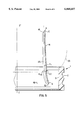
- FIGS. 4 and 5 represent two variants of leaflets according to the invention, in the open position in cross section through a plane passing through the axis of the rim and point D of FIG. 1b.
- the valve prosthesis includes a base 1 comprising an external part 2 forming a suture ring, and an internal part 3 forming a rim in which blood can move from upstream to downstream in the direction of the arrow F.
- Closing leaflets 10, in this case 3 open under the action of the pulsed blood flow in the direction of the arrow F from a nominal closed position (FIG. 2) to a nominal open position (FIGS. 1a and 1b) in which the leaflets 10 are in abutment with the rim 3.
- Each one of the leaflets 10 opens in the physiological direction about the tilt axis 11, and its central region 40 presents a leading edge 12 which, in the closed position, is in contact with the rim 3 along a contour 14 (represented in dotted line in FIG.
- each trailing edge 16 presents, in the case of a prosthesis with more than two leaflets, a distal point C located in the extreme downstream part of the leaflet.
- each one of the leaflets 10 presents an anterior side 17 directed towards the upstream region when the leaflets are closed, and a posterior side 18 directed towards the downstream region when the leaflets 10 are closed.
- the downstream side 18 of each leaflet 10 borders the rim 3, and as a result, once the valve has been placed in a patient, the downstream side 18 of each leaflet 10 also borders a natural wall 20 (wall of the aortic sinus, or of the cavity of the left ventricle) and it forms with the rim 3 and the wall 20 a peripheral duct zone 19 which forms as many narrow passages with respect to the central flow duct delimited by the sides 17.
- the lateral edges 30 prolong, on each side, the central region 40 of each one of the leaflets 10 and they present a contour 15 which extends the contour 14 of the leading edge proper 12 and a contour 31 which extends the trailing edge proper, 16.
- the lateral edges 30 thus constitute transitional profiles between the leading edge 12 and the trailing edge 16.
- the contour 15 of the lateral edges 30 is in contact with the rim 3 and the contours 31 of the lateral edges 30 of the adjacent leaflets 10 come in contact with each other.
- the leading edge proper, 12 is considered to be delimited by the contour 14 of the central region 40 of the leaflet 10, and the trailing edge proper is delimited at the edge 16 of the central region 40.
- a prosthetic valve closes essentially due to the action of the reverse blood flow or reflux in the opposite direction of the arrow F, resulting in a regurgitated closure volume which is not negligible and which can be a very large fraction of the blood flow in the case of a low cardiac output and tachycardia. Since the closure volume is constant, the regurgitated volume per unit of time is proportional to the cardiac rhythm. If, in addition, the cardiac output is low, the closure volume rapidly becomes a large fraction of the ejected volume.
- the invention allows decreasing the closure volume by adapting the profile of the downstream side 18 of the region 40 in such a manner that it presents a zone 22 which turns its concavity towards the rim 3 and thus toward the wall 20, which allows the exploitation of the movements of the blood flow to generate an instantaneous excess pressure on the downstream side 18 of the leaflets at the time of the deceleration of the blood flow.
- the zone 22 extends over a major part of the length L of the corresponding leaflet 10.
- each leaflet presents, in a section through a section plane containing the axis ZZ' of the rim 3 and, the point D closest to the axis of the rim, a profile having a maximum curvature FL M directed towards the axis ZZ' of the rim 3, which is between 1% and 20% of the length L of the leaflet defined as being the maximum distance between a median point A' of the leading edge 12 and a median point B' of the leading edge 16, in the cross section of the leaflet 10 which is parallel to the section plane when the leaflet is in the open position (FIG. 1a).
- the length L of the leaflet is the distance between the leading edge and the trailing edge in the section of the leaflet through the section plane.
- the value of the curvature FL is defined as the distance between the profile and the line joining the ends of the section of the leaflet 10, that is the median point A' of the leading edge 12 and the median point B' of the trailing edge 16 through the above-mentioned section plane. More particularly, with reference to FIGS. 4 and 5, the curvature FL is defined as the distance between the line AB which joins the median point A of the leading edge 12 and the median point B of the trailing edge, and the median line 25 of the leaflet 10.
- the maximum curvature FL M is the maximum value of the curvature FL. The value of the maximum curvature FL M can be between 5% and 15%, preferably between 5% and 10%.
- FIG. 4 illustrates a camber of the leaflet 10 which extends from the leading edge 12 to the trailing edge 16.
- FIG. 5 illustrates a camber of the leaflet 10 which is more accentuated in the vicinity of the leading edge 12 than in the vicinity of the trailing edge 16.
- a camber as defined above appreciably decreases the response time of the tilt of the leaflets and it promotes a rapid closing by holding, like the sails of a boat, the centripetal wall currents generated by the flow.
- the invention applies only to mechanical cardiac valves with two or three leaflets, whose pivoting direction is physiological, that is, from the axis ZZ' of the rim 3 toward the rim 3 during the opening, and, as a corollary, from the rim 3 toward the axis ZZ' of the rim 3 during the closing.
- a camber with concave shape exposed to the centripetal wall currents in the peripheral duct regions not only tends to increase the percentage of closing at the time when the flow becomes zero but also to decrease the time required to complete the closing.
- An adapted camber thus allows a reduction in the dynamic leakage volume.
- the concavity of the posterior side of the leaflets is preferably bidirectional: parallel to the flow axis on the vertical plane and perpendicularly to this axis on the horizontal plane, the leaflets being taken in the open position.
- the concavity parallel to the axis of the blood flow is advantageously of the ellipsoid type with a curvature located near the point C at 2/3 of the length L and the maximum amplitude which can reach 20% of the maximum length L of the leaflet.
- the radius of curvature which is tighter toward the point C allows the closing currents to have a more marked effect on the point C than on the base, thus favoring, as a result of a lever effect, the early tilting of the leaflets 10.
- This spatula-like shape also allows an appreciable increase in the surface area of coaptation of the three leaflets 10 between each other in the closed position, just like in the natural valve.
- the sail surface area being smaller than in the mitral version because of the smaller size, the curvatures of the leaflets 10 are advantageously more marked.
- cambers so defined tend to match the shape of the vortex generated by the flow in the aortic sinuses and in the ventricular cavity and they tend to ensure a good sweeping of the entire downstream side 18 of the leaflets 10 as well as that of their guidance tracks on the three solid parts of the orifice.
- this curvature tends to orient the blood column which flows back towards the internal wall of the orifice of the valve in a direction which is not parallel to the flow axis, which can reduce the shearing forces to which the blood is exposed as it passes through the interstices (see studies of static leakage by CFD).
- the leaflets 10 of the mechanical valve which is the object of the present invention also present considerably different curvatures in the mitral version and in the aortic version.
- the diastolic leakage occurs at a constant pressure of approximately 80 mm Hg for a duration on the order of 450 msec.
- the static leakage of a standard bileaflet valve of size 23 is 300 mL/min for a mean gap width of 4/100 mm.
- the gap width is less critical in its effect on the hemolysis rate than for the mitral valve. The shearing forces on the blood during an aortic leakage would be rather of the laminary type.
- the systolic leakage occurs at the pulse pressure of 0-160 mm Hg for a duration of typically 300 msec and with a higher dP/dT (1500, 3000 and 4500 mm Hg/sec for 70, 90 and 120 cycles per min, respectively).
- the static leakage of a standard bileaflet valve the size 29 is on the order of 230 mL/min for an interstice whose mean width is less than 4/100 mm. Starting with a certain critical value, the increase in the gap width decreases the hemolysis rate. The shearing forces on the blood during a mitral leakage would be rather of the turbulent type.
- Pulheral jets having a length of more than 1 cm around the closed leaflets of the valves marketed by the company St. Jude Medical are observed in the mitral position in all the patients during echo-Doppler examinations. They form characteristic shower head images.
- the manufacturers of bileaflet valve attribute these "jets” to a controlled rinsing function of the joint areas, which reduces the risk of coagulation at this level and thus the catastrophic blockage of the leaflets. Given the configuration of the articulations, these "rinsing jets” are very useful and they explain the low rate of thrombosis observed with these valves.
- the optimal values of the gap under physiological flow, pressure and dP/dT conditions are equal to or larger than approximately 0.8-1/10 mm. Such a large gap is only functionally acceptable if the closure volume is decreased, because otherwise the corresponding total leakage would be entirely prohibitory.
- the closure volume In the mitral position, the closure volume is relatively larger than the static leakage volume. A significant decrease in the closure volume thus permits an appreciably larger gap width. Conversely, in the aortic position, the dynamic closure volume is relatively speaking smaller than the static leakage. One can advantageously reduce the gap width and decrease the static flow.
- the gap width is preferably regulated so as to permit, at a constant pressure of 100 mm Hg, a leakage flow on the order of 0.5 L/min, regardless of size. This value corresponds to a nominal leakage of 2-3% of the systolic volume in the physiological frequency, pressure and flow regimen.
- the total regurgitation rate is then appreciably less than that of the known mechanical prostheses.
- the mean gap width is typically on the order of 2/100 mm.
- the gap width is preferably regulated so as to allow, at a constant pressure of 100 mm Hg, a leakage flow on the order of 0.8 L/min, regardless of the size. This value corresponds to a nominal leakage of 7-8% of the systolic volume in a physiological frequency flow and pressure regimen.
- the total regurgitation rate is identical to or slightly larger than that of the known mechanical prostheses.
- the gap width is at least 4 times larger than the gap width of the aortic valves, or, typically, 0.8-1/10 mm.
- the optimized valve which is the object of the present invention, has a gap width which is larger in the mitral position than in the aortic position.
- Mitral valves are larger than aortic valves.
- the standard size for mitral valves is 29 mm.
- the standard size for aortic valves is 23 mm.
- the "compulsory" closure volume is naturally much larger for mitral valves. Consequently, it is advantageous to reduce the closure volume above all for the mitral configuration.
- the classic monodisk valves or the bileaflet valves close only due to the reflux, at the time of the reversal of the output, at the very beginning of the diastole in the aortic position and at the very beginning of the systole in the mitral position.
- the closure caused by the deceleration of the output is zero, whereas it is almost 90% with natural valves.
- the reflux volume is large, and the closure speed is very high.
- the wall currents generated by the filling of the ventricle or of the sinuses exert a lateral force on the leaflets 10 which return their tip C in the axis direction of the blood output.
- the leaflets 10 then start their closing prematurely, as soon as the flow through the opening decreases.
- the closing speed is less high.
- the compulsory closure volume is smaller, and the time required to complete the closing is shorter, so that the dynamic reflux volume is smaller.
- U.S. Patent No. 4,820,299 (DASSAULT-LAPEYRE) describes a valve having a tilt axis located perpendicularly at a distance of at least 75% of the values of the internal radius R of the opening. This value is appropriate for the aortic definition since the aortic valves are smaller and since the compulsory closure volume is relatively speaking smaller.
Abstract
Description
______________________________________
1/ REGURGITATION EN POSITION MITRALE:
Valve 29 de Carbomedics (CM) contre Valve 29 de St-JUDE MEDICAL
(SJM) (saline, pression aortique = 120/80 mm Hg)
                        CM
                        volume
                              CM    SJM    SJM
Rhythme
       Volume  Debit    de fer-
                              fuite volume de
                                           fuite
cardiaque
       expulse cardiaque
                        meture
                              statique
                                    fermeture
                                           statique
2/     3/      4/       5/    6/    7/     8/
______________________________________
 72/mn 70 ml   4.5 1/mn 5.0 ml
                              2.0 ml
                                     5.5 ml
                                           2.9 ml
120/mn 80 ml   9.0 1/mn 6.0 ml
                              1.9 ml
                                    16.5 ml
                                           1.8 ml
______________________________________
 Key:
 1 REGURGITATION IN MITRAL POSITION: Carbomedics (CM) valve 29 versus St.
 Jude Medical (SJM) valve 29 (saline, aortic pressure = 120/80 mm Hg)
 2 Heart rate
 3 Expelled volume
 4 Cardiac output
 5 CM closure volumes
 6 CM static leakage
 7 SJM closure volume
 8 SJM static leakage
______________________________________
1/ REGURGITATION EN POSITION AORTIQUE:
Valve 23 de Carbomedics (CM) contre Valve 23 de St-JUDE MEDICAL
(SJM) (saline, pression aortique = 120/80 mm Hg)
                        CM
                        volume
                              CM    SJM    SJM
Rhythme
       Volume  Debit    de fer-
                              fuite volume de
                                           fuite
cardiaque
       expulse cardiaque
                        meture
                              statique
                                    fermeture
                                           statique
2/     3/      4/       5/    6/    7/     8/
______________________________________
 72/mn 70 ml   4.5 1/mn 1.5 ml
                              4.9 ml
                                    2.8 ml 5.0 ml
120/mn 80 ml   9.0 1/mn 1.8 ml
                              2.6 ml
                                    3.0 ml 4.3 ml
______________________________________
 Key:
 1 REGURGITATION IN AORTIC POSITION: Carbomedics (CM) valve 23 versus St.
 Jude Medical (SJM) valve 23 (saline, aortic pressure = 120/80 mm Hg)
 2 Heart rate
 3 Expelled volume
 4 Cardiac output
 5 CM closure volumes
 6 CM static leakage
 7 SJM closure volume
 8 SJM static leakage
Claims (15)
Priority Applications (2)
| Application Number | Priority Date | Filing Date | Title |
|---|---|---|---|
| US09/035,981 US6068657A (en) | 1997-05-20 | 1998-03-06 | Mechanical valve prosthesis with optimized closing mode |
| US09/323,402 US6395024B1 (en) | 1997-05-20 | 1999-06-01 | Mechanical heart valve |
Applications Claiming Priority (2)
| Application Number | Priority Date | Filing Date | Title |
|---|---|---|---|
| US85953097A | 1997-05-20 | 1997-05-20 | |
| US09/035,981 US6068657A (en) | 1997-05-20 | 1998-03-06 | Mechanical valve prosthesis with optimized closing mode |
Related Parent Applications (1)
| Application Number | Title | Priority Date | Filing Date |
|---|---|---|---|
| US85953097A Continuation | 1997-05-20 | 1997-05-20 |
Related Child Applications (1)
| Application Number | Title | Priority Date | Filing Date |
|---|---|---|---|
| US09/323,402 Continuation-In-Part US6395024B1 (en) | 1997-05-20 | 1999-06-01 | Mechanical heart valve |
Publications (1)
| Publication Number | Publication Date |
|---|---|
| US6068657A true US6068657A (en) | 2000-05-30 |
Family
ID=25331137
Family Applications (1)
| Application Number | Title | Priority Date | Filing Date |
|---|---|---|---|
| US09/035,981 Expired - Lifetime US6068657A (en) | 1997-05-20 | 1998-03-06 | Mechanical valve prosthesis with optimized closing mode |
Country Status (1)
| Country | Link |
|---|---|
| US (1) | US6068657A (en) |
Cited By (20)
| Publication number | Priority date | Publication date | Assignee | Title |
|---|---|---|---|---|
| US20030139805A1 (en) * | 2002-01-24 | 2003-07-24 | Holmberg William R. | Conduit for aorta or pulmonary artery replacement |
| US20040122515A1 (en) * | 2002-11-21 | 2004-06-24 | Xi Chu | Prosthetic valves and methods of manufacturing |
| US6890352B1 (en) * | 1999-12-14 | 2005-05-10 | Jcl Technic Ab | Vessel valve |
| US7951197B2 (en) | 2005-04-08 | 2011-05-31 | Medtronic, Inc. | Two-piece prosthetic valves with snap-in connection and methods for use |
| US7959674B2 (en) * | 2002-07-16 | 2011-06-14 | Medtronic, Inc. | Suture locking assembly and method of use |
| US7967857B2 (en) | 2006-01-27 | 2011-06-28 | Medtronic, Inc. | Gasket with spring collar for prosthetic heart valves and methods for making and using them |
| US7972377B2 (en) | 2001-12-27 | 2011-07-05 | Medtronic, Inc. | Bioprosthetic heart valve |
| US7981153B2 (en) | 2002-12-20 | 2011-07-19 | Medtronic, Inc. | Biologically implantable prosthesis methods of using |
| US20110196482A1 (en) * | 2008-10-10 | 2011-08-11 | Milux Holding S.A. | Improved artificial valve |
| US8021421B2 (en) | 2003-08-22 | 2011-09-20 | Medtronic, Inc. | Prosthesis heart valve fixturing device |
| US8211169B2 (en) | 2005-05-27 | 2012-07-03 | Medtronic, Inc. | Gasket with collar for prosthetic heart valves and methods for using them |
| WO2012162522A3 (en) * | 2011-05-26 | 2013-01-17 | On-X Life Technologies, Inc. | Heart valve sewing cuff |
| US20130110229A1 (en) * | 2010-04-30 | 2013-05-02 | Leo Antonovich Bokeriya | Aortal tricuspid heart valve prosthesis |
| EP2626040A1 (en) * | 2007-05-02 | 2013-08-14 | Lapeyre Industries Llc | Mechanical prosthetic heart valve |
| US8603161B2 (en) | 2003-10-08 | 2013-12-10 | Medtronic, Inc. | Attachment device and methods of using the same |
| US20140228937A1 (en) * | 2013-02-11 | 2014-08-14 | Joshua Krieger | Expandable Support Frame and Medical Device |
| US8821569B2 (en) | 2006-04-29 | 2014-09-02 | Medtronic, Inc. | Multiple component prosthetic heart valve assemblies and methods for delivering them |
| US20210212821A1 (en) * | 2020-01-14 | 2021-07-15 | Novostia Sa | Mechanical prosthetic heart valve |
| US11751992B2 (en) | 2020-01-14 | 2023-09-12 | Novostia Sa | Mechanical prosthetic heart valve |
| US11826247B2 (en) | 2020-01-14 | 2023-11-28 | Novostia Sa | Mechanical prosthetic heart valve |
Citations (14)
| Publication number | Priority date | Publication date | Assignee | Title |
|---|---|---|---|---|
| US4120299A (en) * | 1976-04-23 | 1978-10-17 | Russo Joseph J | Snore-prevention article and process for manufacturing the same |
| US4676789A (en) * | 1985-05-16 | 1987-06-30 | Sorensen H Rahbek | Heart valve |
| US4808180A (en) * | 1987-04-29 | 1989-02-28 | Medtronic, Inc. | Prosthetic heart valve |
| US4820299A (en) * | 1985-09-23 | 1989-04-11 | Avions Marcel Dassault-Breguet Aviation | Prosthetic cardiac valve |
| US4872875A (en) * | 1989-01-28 | 1989-10-10 | Carbon Implants, Inc. | Prosthetic heart valve |
| US5026391A (en) * | 1985-07-24 | 1991-06-25 | Mcqueen David M | Curved butterfly bileaflet prosthetic cardiac valve |
| US5080669A (en) * | 1990-02-12 | 1992-01-14 | Manuel Tascon | Prosthetic heart valve |
| WO1992002197A1 (en) * | 1990-08-09 | 1992-02-20 | Christian Olin | Heart valve prosthesis |
| US5116367A (en) * | 1989-08-11 | 1992-05-26 | Ned H. C. Hwang | Prosthetic heart valve |
| US5123918A (en) * | 1989-02-15 | 1992-06-23 | Dassault Aviation | Prosthetic heart valve |
| US5207707A (en) * | 1992-01-16 | 1993-05-04 | Carbomedics, Inc. | Tri-leaflet all carbon heart valve |
| WO1993017637A1 (en) * | 1992-03-13 | 1993-09-16 | Jcl Technic Ab | Cardiac valve |
| US5314467A (en) * | 1991-06-06 | 1994-05-24 | Medtronic, Inc. | Composite curvature bileaflet prosthetic heart valve with serpentine curve hinge recesses |
| US5843183A (en) * | 1997-05-13 | 1998-12-01 | Bokros; Jack C. | Trileaflet heart valve |
-
1998
- 1998-03-06 US US09/035,981 patent/US6068657A/en not_active Expired - Lifetime
Patent Citations (14)
| Publication number | Priority date | Publication date | Assignee | Title |
|---|---|---|---|---|
| US4120299A (en) * | 1976-04-23 | 1978-10-17 | Russo Joseph J | Snore-prevention article and process for manufacturing the same |
| US4676789A (en) * | 1985-05-16 | 1987-06-30 | Sorensen H Rahbek | Heart valve |
| US5026391A (en) * | 1985-07-24 | 1991-06-25 | Mcqueen David M | Curved butterfly bileaflet prosthetic cardiac valve |
| US4820299A (en) * | 1985-09-23 | 1989-04-11 | Avions Marcel Dassault-Breguet Aviation | Prosthetic cardiac valve |
| US4808180A (en) * | 1987-04-29 | 1989-02-28 | Medtronic, Inc. | Prosthetic heart valve |
| US4872875A (en) * | 1989-01-28 | 1989-10-10 | Carbon Implants, Inc. | Prosthetic heart valve |
| US5123918A (en) * | 1989-02-15 | 1992-06-23 | Dassault Aviation | Prosthetic heart valve |
| US5116367A (en) * | 1989-08-11 | 1992-05-26 | Ned H. C. Hwang | Prosthetic heart valve |
| US5080669A (en) * | 1990-02-12 | 1992-01-14 | Manuel Tascon | Prosthetic heart valve |
| WO1992002197A1 (en) * | 1990-08-09 | 1992-02-20 | Christian Olin | Heart valve prosthesis |
| US5314467A (en) * | 1991-06-06 | 1994-05-24 | Medtronic, Inc. | Composite curvature bileaflet prosthetic heart valve with serpentine curve hinge recesses |
| US5207707A (en) * | 1992-01-16 | 1993-05-04 | Carbomedics, Inc. | Tri-leaflet all carbon heart valve |
| WO1993017637A1 (en) * | 1992-03-13 | 1993-09-16 | Jcl Technic Ab | Cardiac valve |
| US5843183A (en) * | 1997-05-13 | 1998-12-01 | Bokros; Jack C. | Trileaflet heart valve |
Non-Patent Citations (20)
| Title |
|---|
| C. Peskin et al., "The aortic sinus vortex", Federation Proceedings, Dec. 1978, vol. 37, No. 14, pp. 2784-2792. |
| C. Peskin et al., The aortic sinus vortex , Federation Proceedings, Dec. 1978, vol. 37, No. 14, pp. 2784 2792. * |
| H. Baumgartner et al., "Color Doppler Regurgitant Characteristics of Normal Mechanical Mitral Valve Prostheses In Vitro", Circulation, vol. 85, No. 1, Jan. 1992, pp. 323-332. |
| H. Baumgartner et al., Color Doppler Regurgitant Characteristics of Normal Mechanical Mitral Valve Prostheses In Vitro , Circulation, vol. 85, No. 1, Jan. 1992, pp. 323 332. * |
| J. Skoularigis et al., "Frequency and Severity of Intravascular Hemolysis After Left-Sided Cardiac Valve Replacement with Medtronic Hall and St. Jude Medical Prostheses, and Influence of Prosthetic Type, Position, Size and Number", The American Journal of Cardiology, Mar. 1, 1993, pp. 587-591. |
| J. Skoularigis et al., Frequency and Severity of Intravascular Hemolysis After Left Sided Cardiac Valve Replacement with Medtronic Hall and St. Jude Medical Prostheses, and Influence of Prosthetic Type, Position, Size and Number , The American Journal of Cardiology, Mar. 1, 1993, pp. 587 591. * |
| J. T. Baldwin et al., "Mean Velocities and Reynolds Stresses Within Regurgitant Jets Produced by Tilting Disc Valves", ASAIO Transactions, Jul.-Sep. 1991, vol. 37, No. 3, ISSN 0889-7190, pp. M348-M349. |
| J. T. Baldwin et al., Mean Velocities and Reynolds Stresses Within Regurgitant Jets Produced by Tilting Disc Valves , ASAIO Transactions, Jul. Sep. 1991, vol. 37, No. 3, ISSN 0889 7190, pp. M348 M349. * |
| K. Dellsperger et al., "Regurgitation of Prosthetic Heart Valves: Dependence on Heart Rate and Cardiac Output", The American Journal of Cardiology, Jan. 15, 1983, pp. 321-328. |
| K. Dellsperger et al., Regurgitation of Prosthetic Heart Valves: Dependence on Heart Rate and Cardiac Output , The American Journal of Cardiology, Jan. 15, 1983, pp. 321 328. * |
| M. Jones et al., "Doppler Color Flow Evaluation of Prosthetic Mitral Valves: Experimental Epicardial Studies", Journal of the American College of Cardiology, Jan. 1989, vol. 13, No. 1, pp. 234-240. |
| M. Jones et al., Doppler Color Flow Evaluation of Prosthetic Mitral Valves: Experimental Epicardial Studies , Journal of the American College of Cardiology, Jan. 1989, vol. 13, No. 1, pp. 234 240. * |
| R. Koppensteiner et al., "Blood Rheology After Cardiac Valve Replacement with Mechanical Prostheses or Bioprostheses", The American Journal of Cardiology, Jan. 1, 1991, pp. 79-83. |
| R. Koppensteiner et al., Blood Rheology After Cardiac Valve Replacement with Mechanical Prostheses or Bioprostheses , The American Journal of Cardiology, Jan. 1, 1991, pp. 79 83. * |
| R. T. Johnston et al., "Carbomedics and St. Jude Medical bileaflet valves: an in vitro and in vivo comparison", European Journal of Cariothoracic Surgery, vol. 6, No. 4, 1992, pp. 267-271. |
| R. T. Johnston et al., Carbomedics and St. Jude Medical bileaflet valves: an in vitro and in vivo comparison , European Journal of Cariothoracic Surgery, vol. 6, No. 4, 1992, pp. 267 271. * |
| T. C. Lamson et al., "Relative Blood Damage in the Three Phases of a Prosthetic Heart Valve Flow Cycle", ASAIO Journal, Jul.-Sep. 1993, vol. 39--No. 3, ISSN 1-58-2916, pp. M626-M633. |
| T. C. Lamson et al., Relative Blood Damage in the Three Phases of a Prosthetic Heart Valve Flow Cycle , ASAIO Journal, Jul. Sep. 1993, vol. 39 No. 3, ISSN 1 58 2916, pp. M626 M633. * |
| Y. Kiyota et al., "In vitro closing behavior of the St. Jude Medical heart valve in the pulmonary position," The Journal of Thoracic and Cardiovascular Surgery, Sep. 1992, vol. 104, No. 3, pp. 779-785. |
| Y. Kiyota et al., In vitro closing behavior of the St. Jude Medical heart valve in the pulmonary position, The Journal of Thoracic and Cardiovascular Surgery, Sep. 1992, vol. 104, No. 3, pp. 779 785. * |
Cited By (35)
| Publication number | Priority date | Publication date | Assignee | Title |
|---|---|---|---|---|
| US6890352B1 (en) * | 1999-12-14 | 2005-05-10 | Jcl Technic Ab | Vessel valve |
| US7972377B2 (en) | 2001-12-27 | 2011-07-05 | Medtronic, Inc. | Bioprosthetic heart valve |
| US7018404B2 (en) * | 2002-01-24 | 2006-03-28 | St. Jude Medical, Inc. | Conduit for aorta or pulmonary artery replacement |
| US20030139805A1 (en) * | 2002-01-24 | 2003-07-24 | Holmberg William R. | Conduit for aorta or pulmonary artery replacement |
| US7959674B2 (en) * | 2002-07-16 | 2011-06-14 | Medtronic, Inc. | Suture locking assembly and method of use |
| US8349003B2 (en) | 2002-07-16 | 2013-01-08 | Medtronic, Inc. | Suture locking assembly and method of use |
| US20040122515A1 (en) * | 2002-11-21 | 2004-06-24 | Xi Chu | Prosthetic valves and methods of manufacturing |
| US8460373B2 (en) | 2002-12-20 | 2013-06-11 | Medtronic, Inc. | Method for implanting a heart valve within an annulus of a patient |
| US8551162B2 (en) | 2002-12-20 | 2013-10-08 | Medtronic, Inc. | Biologically implantable prosthesis |
| US10595991B2 (en) | 2002-12-20 | 2020-03-24 | Medtronic, Inc. | Heart valve assemblies |
| US8025695B2 (en) | 2002-12-20 | 2011-09-27 | Medtronic, Inc. | Biologically implantable heart valve system |
| US9333078B2 (en) | 2002-12-20 | 2016-05-10 | Medtronic, Inc. | Heart valve assemblies |
| US8623080B2 (en) | 2002-12-20 | 2014-01-07 | Medtronic, Inc. | Biologically implantable prosthesis and methods of using the same |
| US7981153B2 (en) | 2002-12-20 | 2011-07-19 | Medtronic, Inc. | Biologically implantable prosthesis methods of using |
| US8021421B2 (en) | 2003-08-22 | 2011-09-20 | Medtronic, Inc. | Prosthesis heart valve fixturing device |
| US8747463B2 (en) | 2003-08-22 | 2014-06-10 | Medtronic, Inc. | Methods of using a prosthesis fixturing device |
| US8603161B2 (en) | 2003-10-08 | 2013-12-10 | Medtronic, Inc. | Attachment device and methods of using the same |
| US7951197B2 (en) | 2005-04-08 | 2011-05-31 | Medtronic, Inc. | Two-piece prosthetic valves with snap-in connection and methods for use |
| US8500802B2 (en) | 2005-04-08 | 2013-08-06 | Medtronic, Inc. | Two-piece prosthetic valves with snap-in connection and methods for use |
| US8211169B2 (en) | 2005-05-27 | 2012-07-03 | Medtronic, Inc. | Gasket with collar for prosthetic heart valves and methods for using them |
| US7967857B2 (en) | 2006-01-27 | 2011-06-28 | Medtronic, Inc. | Gasket with spring collar for prosthetic heart valves and methods for making and using them |
| US8821569B2 (en) | 2006-04-29 | 2014-09-02 | Medtronic, Inc. | Multiple component prosthetic heart valve assemblies and methods for delivering them |
| EP2626040A1 (en) * | 2007-05-02 | 2013-08-14 | Lapeyre Industries Llc | Mechanical prosthetic heart valve |
| US20110196482A1 (en) * | 2008-10-10 | 2011-08-11 | Milux Holding S.A. | Improved artificial valve |
| US10226329B2 (en) * | 2008-10-10 | 2019-03-12 | Peter Forsell | Artificial valve |
| US20130110229A1 (en) * | 2010-04-30 | 2013-05-02 | Leo Antonovich Bokeriya | Aortal tricuspid heart valve prosthesis |
| WO2012162522A3 (en) * | 2011-05-26 | 2013-01-17 | On-X Life Technologies, Inc. | Heart valve sewing cuff |
| US9788947B2 (en) | 2011-05-26 | 2017-10-17 | On-X Life Technologies, Inc. | Heart valve sewing cuff |
| US9314333B2 (en) | 2011-05-26 | 2016-04-19 | On-X Life Technologies, Inc. | Heart valve sewing cuff |
| US10695169B2 (en) | 2011-05-26 | 2020-06-30 | On-X Life Technologies, Inc. | Heart valve sewing cuff |
| US20140228937A1 (en) * | 2013-02-11 | 2014-08-14 | Joshua Krieger | Expandable Support Frame and Medical Device |
| US20210212821A1 (en) * | 2020-01-14 | 2021-07-15 | Novostia Sa | Mechanical prosthetic heart valve |
| US11607312B2 (en) * | 2020-01-14 | 2023-03-21 | Novostia Sa | Mechanical prosthetic heart valve |
| US11751992B2 (en) | 2020-01-14 | 2023-09-12 | Novostia Sa | Mechanical prosthetic heart valve |
| US11826247B2 (en) | 2020-01-14 | 2023-11-28 | Novostia Sa | Mechanical prosthetic heart valve |
Similar Documents
| Publication | Publication Date | Title |
|---|---|---|
| US6068657A (en) | Mechanical valve prosthesis with optimized closing mode | |
| US6395024B1 (en) | Mechanical heart valve | |
| Robicsek | Leonardo da Vinci and the sinuses of Valsalva | |
| RU2475212C2 (en) | Mechanical cardiac valve | |
| RU2130760C1 (en) | Bicuspid heart valve prosthesis | |
| JPH064081B2 (en) | Artificial heart valve | |
| US6395025B1 (en) | Mechanical heart valve prosthesis | |
| US20080086202A1 (en) | Mechanical heart valve | |
| Van Nooten et al. | Clinical experience with the first 100 ATS heart valve implants | |
| US11819402B2 (en) | Apex bileaflet mechanical valve | |
| US4950287A (en) | Bicurved leaflet(s) prosthetic heart valve | |
| AU2003244523B2 (en) | Mechanical heart valve | |
| Strüber et al. | Hydrodynamic function of tilting disc prostheses and bileaflet valves in double valve replacement | |
| JP3364142B2 (en) | Artificial heart valve | |
| Kleine et al. | Initial in vivo results of the new Medtronic Advantage™ bileaflet valve in aortic position and comparison to the SJM | |
| MXPA00011791A (en) | Mechanical heart valve | |
| FR2737655A1 (en) | Prosthetic heart flap valve - has two or more closure shutters located within internal rim of suturing ring, with shaped end regions to control pressure characteristics | |
| Forléo | Application of passive flow control to mitigate the thromboembolic potential of bileaflet mechanical heart valves: an in-vitro study | |
| Verdonck et al. | Biofluid mechanics and the circulatory system | |
| Reid | The design characteristics of heart valves | |
| Milo et al. | Bubble Formation on St. Jude Medical Mechanical Heart Valves: An In-Vitro Study | |
| RU2062069C1 (en) | Artificial mitral valve | |
| JPH01227755A (en) | Heart artificial valve | |
| DE102006036949A1 (en) | Heart valve prosthesis, has valve that is attached in part supported in valve and forces blood stream in flow direction of additional flow vector so that blood flows in spiral stream | |
| CZ20004531A3 (en) | Mechanical heart valve |
Legal Events
| Date | Code | Title | Description |
|---|---|---|---|
| STCF | Information on status: patent grant |
Free format text: PATENTED CASE |
|
| AS | Assignment |
Owner name: LAPEYRE, DIDIER, DR., FRANCE Free format text: OTHER - JOINT OWNERSHIP AGREEMENT;ASSIGNOR:TRIFLO MEDICAL INC.;REEL/FRAME:012795/0950 Effective date: 19981022 Owner name: ORTIZ, GEORGE, FRANCE Free format text: OTHER - JOINT OWNERSHIP AGREEMENT;ASSIGNOR:TRIFLO MEDICAL INC.;REEL/FRAME:012795/0950 Effective date: 19981022 Owner name: DE LA FRESSANGE, ANDRE, FRANCE Free format text: OTHER - JOINT OWNERSHIP AGREEMENT;ASSIGNOR:TRIFLO MEDICAL INC.;REEL/FRAME:012795/0950 Effective date: 19981022 Owner name: DE IN FRESSANGE, YVAN, FRANCE Free format text: OTHER - JOINT OWNERSHIP AGREEMENT;ASSIGNOR:TRIFLO MEDICAL INC.;REEL/FRAME:012795/0950 Effective date: 19981022 Owner name: LAGESSE, JEAN-CLAUDE, FRANCE Free format text: OTHER - JOINT OWNERSHIP AGREEMENT;ASSIGNOR:TRIFLO MEDICAL INC.;REEL/FRAME:012795/0950 Effective date: 19981022 |
|
| AS | Assignment |
Owner name: LAPEYRE GROUP THE, FRANCE Free format text: CORRECTIVE ASSIGNMENT TO CHANGE CONVEYING PARTY AND RECEIVING PARTY PREVIOUSLY RECORDED AT REEL 012795 FRAME 0950;ASSIGNOR:LAPEYRE, DIDIER DR.;REEL/FRAME:013146/0831 Effective date: 19981022 |
|
| FEPP | Fee payment procedure |
Free format text: PETITION RELATED TO MAINTENANCE FEES FILED (ORIGINAL EVENT CODE: PMFP); ENTITY STATUS OF PATENT OWNER: LARGE ENTITY |
|
| FEPP | Fee payment procedure |
Free format text: PETITION RELATED TO MAINTENANCE FEES GRANTED (ORIGINAL EVENT CODE: PMFG); ENTITY STATUS OF PATENT OWNER: LARGE ENTITY |
|
| REMI | Maintenance fee reminder mailed | ||
| FPAY | Fee payment |
Year of fee payment: 4 |
|
| SULP | Surcharge for late payment | ||
| PRDP | Patent reinstated due to the acceptance of a late maintenance fee |
Effective date: 20040730 |
|
| FPAY | Fee payment |
Year of fee payment: 8 |
|
| FPAY | Fee payment |
Year of fee payment: 12 |