US6083149A - Magnetic field device and method for inhibiting angiogenesis and retarding growth rates of tumors in mammals - Google Patents
Magnetic field device and method for inhibiting angiogenesis and retarding growth rates of tumors in mammals Download PDFInfo
- Publication number
- US6083149A US6083149A US09/111,769 US11176998A US6083149A US 6083149 A US6083149 A US 6083149A US 11176998 A US11176998 A US 11176998A US 6083149 A US6083149 A US 6083149A
- Authority
- US
- United States
- Prior art keywords
- coil
- magnetic field
- frame
- electrical
- wire
- Prior art date
- Legal status (The legal status is an assumption and is not a legal conclusion. Google has not performed a legal analysis and makes no representation as to the accuracy of the status listed.)
- Expired - Fee Related
Links
Images


Classifications
-
- A—HUMAN NECESSITIES
- A61—MEDICAL OR VETERINARY SCIENCE; HYGIENE
- A61N—ELECTROTHERAPY; MAGNETOTHERAPY; RADIATION THERAPY; ULTRASOUND THERAPY
- A61N2/00—Magnetotherapy
- A61N2/02—Magnetotherapy using magnetic fields produced by coils, including single turn loops or electromagnets
-
- A—HUMAN NECESSITIES
- A61—MEDICAL OR VETERINARY SCIENCE; HYGIENE
- A61K—PREPARATIONS FOR MEDICAL, DENTAL OR TOILETRY PURPOSES
- A61K41/00—Medicinal preparations obtained by treating materials with wave energy or particle radiation ; Therapies using these preparations
- A61K41/0052—Thermotherapy; Hyperthermia; Magnetic induction; Induction heating therapy
Definitions
- Angiogenesis may be defined as the formation, or the initiation, of the growth of blood carrying vessels or capillaries in a biological subject, particularly mammals.
- the present invention and/or discovery (hereinafter collectively and individually referred to as the "invention" even though the subject matter of this application may comprise a discovery, an invention, or a combination thereof) is directed to the use of a device capable of producing a magnetic field or flux field found useful to inhibit angiogenesis in mammals. It is believed that the present invention was universally unknown to civilization prior to the time it became known the inventors hereof.
- the vessel wall is composed of an endothelial cell lining, a basement membrane, and a layer of cells called pericytes which partially surround the endothelium.
- the pericytes are contained within the same basement membrane as the endothelial cells and occasionally make direct contact with them. (See Background Figure A).
- angiogenic factors (the black triangles) bind to endothelial cell receptors and initiate the sequence of angiogenesis.
- endothelial cells When the endothelial cells are stimulated to grow, they secrete proteases which digest the basement membrane surrounding the vessel. The junctions between endothelial cells are altered, cell projections pass through the space created and the newly formed sprout grows towards the source of the stimulus.
- capillary sprout growth is dependent upon several processes: the stimulus for growth (angiogenic factors, hypoxia, etc.) must be maintained; the endothelial cells must secrete the proteases required to break down the adjacent tissue; the cells themselves must be capable of movement/migration; and endothelial cell division must take place to provide the necessary number of cells (this takes place at a site behind the growth front of the sprout). Neighboring blind-ended sprouts then join together to form a capillary loop which later matures into a vessel like the one from which it arose.
- angiogenesis dependent diseases includes, but is not limited to the following: Angiofibroma which is an abnormal formation of blood vessels which are prone to bleeding; Neovascular Glaucoma which is an abnormal growth of blood vessels in the eye; Arteriovenous malformations which is an abnormal communication between arteries and veins; Nonunion fractures which are fractures that will not heal; Lupus, and other Connective Tissue Disorders; Osler-Weber syndrome which is a genetic condition resulting in abnormal blood vessels which are prone to bleeding; Atherosclerotic plaques which is a hardening of the arteries; Psoriasis which is a common chronic skin condition; Corneal graft neovascularization which is a complication of corneal replacement surgery; Pyogenic granuloma which is a common skin lesion composed of blood vessels; Delayed wound healing; Diabetic retinopathy which is a leading cause of blindness in diabetics; Scleroderma which is a form of connective tissue disease; Granulations (burns (burn
- Magnetism is a property of charge in motion and is related to electrical theory. As set forth in the examples, the target is mammalian tissue. A magnetic field surrounds a conductor through which current travels according to the well known "right hand rule”. It is also known that a magnetic field of flux can induce current flow in circuits.
- An embodiment of the present invention is directed to a device for establishing or otherwise creating a substantially contained field of magnetic energy.
- a magnetic field produced solely by a current carrying coil can be said to constitute an electromagnetic field for purposes of this discussion.
- the invention and its various embodiments comprise a current carrying wire for producing a magnetic field around the wire in accordance with the well known "right hand rule" (i.e., clockwise or counterclockwise around the wire, depending upon the direction of the current flow, when viewed from a hypothetical common cross-sectional face.).
- the preferred embodiments of the present invention were found useful for affecting angiogenesis and retarding the growth rates of cancerous tumors in mammals such as laboratory mice.
- the preferred embodiment is a coil of conductor such as a wire with a voltage drop across its opposing ends wherein the affect on angiogenesis and retardation of tumor growth has been observed to be statistically significant, as verified by independent laboratory research tests, within the area bounded by the coil (i.e., within the confines of the coil).
- Tumors cannot thrive without sufficient nutrition provided by the increased circulation of blood achieved through angiogenesis. Improved wound healing may also be explained by a reduction in angiogenesis. In the wound healing process, excessive angiogenesis is believed to lead to scar formation and inefficient (and thereby slower) healing. Pharmaceutical anti-angiogenic agents have reportedly improved wound healing by limiting angiogenic activity and avoiding pathologic angiogenesis. Pathologic angiogenesis is also present in such diseases as arthritis and autoimmune diseases (such as lupus and colitis). Therefore, it is currently believed that the common effects of an magnetic field are derived by modulating the effects of transforming growth factor beta (TGFb) alone or in combination with some other cellular or ionic effect.
- TGFb transforming growth factor beta
- TGFb is involved in a number of physiological processes, including cell growth and differentiation, embryonic development, extracellular matrix formation, bone remodeling, wound healing, immune function, and angiogenesis. It is further believed that an increased expression of TGFb may mediate such activities as autoimmune disease. In addition, increased serum expression of TGFb has been shown to relieve rheumatoid arthritis symptoms.
- TGFb The regulation of TGFb by the magnetic field of the present invention is explained by its varied effects of the field. It is unknown for certain, but it is believed that this regulation involves the expression of TGFb, either by itself or through the receptors for TGFb located on various target cells. Because of the magnetic and electrical elements of the field produced by the present invention and its application to a biological system, it is further believed that the receptors for TGFb provide the motive messaging to the target cells to affect TGFb. For example, the field could cause the cell to perform as though is had bound to TGFb by activating the TGFb receptors (especially the TGFb receptor 2).
- TGFb R2 TGFb receptor 2
- the EMF field has major components carrying frequency harmonics of 60 hertz (i.e., frequencies at 60 Hz, 120 Hz, 240 Hz, 480 Hz, etc.).
- frequency harmonics of 60 hertz (i.e., frequencies at 60 Hz, 120 Hz, 240 Hz, 480 Hz, etc.).
- the presence of a field and its induced current at a frequency of 120 Hz is believed to cause the TGFb receptor to act as though it had been bound by TGFb. This effect would cause the same result in a biological system as an infusion or increased expression of TGFb.
- This frequency response, induced by the field produced by the present invention is believed to be associated with the field's strong frequency expression at 120 Hz and its harmonics and sub-harmonics.
- the field at an amplitude of approximately 15-17 mT should induce a voltage of approximately one to ten millivolts with a current of approximately 10 milliamps in a subject exposed to the field. This voltage and amperage are sufficient to induce a biological effect in the subject.
- an effect on either the expression or reception of an angiogenic growth factor such as vascular endothelial growth factor (VEGF) or basic fibroblast growth factor (bFGF) would help explain the robust effect achieved by the field of the present invention in inhibiting angiogenesis.
- an angiogenic growth factor such as vascular endothelial growth factor (VEGF) or basic fibroblast growth factor (bFGF)
- VEGF vascular endothelial growth factor
- bFGF basic fibroblast growth factor
- An embodiment of the apparatus portion of the present discovery and invention includes a plurality of permanent magnets which are positioned about the periphery of a geometric frame in the form of a circle, rectangle, square or other shape such as the preferred ellipsoidal shape having a central opening.
- the preferred embodiment incorporates an ellipsoidal shape comprised of multiple arc length segments and therefore does not resemble a true ellipse, even though such approximations might not be detectable to the human eye.
- the preferred embodiment comprises a tightly wound coil of continuous wire wrapped about a non-conductive frame, preferably made of phenolic resin impregnated spun glass fibers, in a manner similar to winding thread around a spool.
- a current is passed through the coil in one of two directions "+" positive or "-”. negative, (i.e., to the right or to the left).
- the current carrying coil produces a magnetic field.
- the number of coil wire turns may vary.
- Various embodiments of the present inventive apparatus incorporate devices using between fifty (50) and one thousand two hundred (1200) turns of insulated copper wire, because of the heat generated in the coil due to the inherent resistance of the wire to carry a current.
- Still other verifying studies are ongoing using devices having more or less windings than the exemplary ranges just specified (e.g., one thousand six hundred (1,600)).
- the coils themselves may be a single coil or multiple individual coils in a stacked or adjacent relationship where the total number of coil windings is counted.
- an optional thermal sensor or array of thermal sensors of either the resistance or thermocouple type is included within the coil assembly.
- the sensors measure and allow quantification of the coil temperature at various points corresponding to the placement of the sensors.
- the optional thermal sensors therefore, enable the operator to monitor the amount of heat generated by the device during use.
- the preferred power supply incorporates a variac type transformer capable of delivering up to the preferred amperage range of 0-15 amperes of current.
- the corresponding voltage to achieve the 0-15 ampere range depends upon the number of turns of wire used to form the coil, but typically includes a 110 or 220 volt (i.e., 110 V or 220 V) 60 cycle (hertz or Hz) supply voltage for studies done in the United States.
- Other supply voltages are contemplated depending upon the nature of the electrical distribution of the locality in which the apparatus is used.
- the AC input voltage applied to the coil is passed through a voltage regulating device for modulating (i.e., increasing or decreasing) the voltage as desired by the operator depending upon the application.
- a transformer is used to provide a preselected steady state voltage (i.e., the working voltage from the variac type device) emerging therefrom.
- the working voltage is directed to a rectifier to convert the AC input to a DC output.
- the AC voltage is preferably rectified by a full-wave rectifier set.
- the rectifier converts the applied AC current to a direct current (DC) with a resulting ripple frequency of either 60 cycles per second (i.e., half wave rectification) or 120 cycles per second (i.e., fill wave rectification) depending upon the rectifier setup.
- the harmonics of 60 cycles or 120 cycles are also believed to be useful to achieve the desired result, or they may be filtered to eliminate them and their associated affects.
- fifty (50) cycle per second current is used as the AC supply voltage
- the resulting ripple frequency is either 50 or 100 cycles per second depending upon the rectification.
- the nature of the wave form is best described as a DC one half sine wave configuration.
- an apparatus for inhibiting angiogenesis and retarding the growth of cancerous tumors present in mammalian subjects comprising means for producing a magnetic field, wherein the means includes a coil assembly including at least one electrical conductor wrapped around a frame defining a coil assembly interior; and a source of DC electrical energy for supplying a DC electrical current to the length of electrical conductor to create a magnetic field within the interior of the coil.
- the at least one electrical conductor may further include a plurality of electrical conductors around the frame.
- the device also preferably includes an enclosure means for shielding the coil.
- the enclosure means consists of a side plate and a cover.
- the frame is substantially elliptical in shape.
- a switch system capable of regulating the direction of the current flow through the coil is also provided. In the absence of natural magnets a switch means is not needed.
- a rectifier means for rectifying the incoming AC electrical energy is also provided.
- the rectifier means may provide either full wave or half wave DC rectification of a wave form associated with the DC electrical energy, and a plurality of DC bridge rectifiers may be used where the incoming AC working voltage and current is split from a single source to form a plurality of sources.
- at least one thermocouple sensor is positioned adjacent to at least one electrical conductor for measuring the temperature of the conductor.
- the at least one electrical conductor is wrapped around the frame between 50 and 1600 times, and each of the plurality of electrical conductors may also be wrapped around the frame between 50 and 1600 times.
- the working current is preferably in the amperage range from approximately 5 amps and 10 amps, but other ranges such as between 2 and 20 amps are also believed to be useful and remain within the scope of the present invention.
- the present invention may also be summarized as a means for inhibiting angiogenesis and retarding the growth of cancerous tumors present in mammalian subjects, comprising a coil assembly including at least one electrical conductor wrapped around a frame defining a coil assembly interior; and a source of DC electrical energy for supplying a DC electrical current to the length of electrical conductor to create a magnetic field within the interior of the coil.
- the present invention may also be summarized as an inventive apparatus capable of producing a magnetic field for retarding or inhibiting angiogenesis and the growth of cancerous tumors present in mammalian subjects, comprising a coil assembly including at least one length of electrically conducting wire wrapped about a frame which defines an interior of the coil assembly; and DC voltage means for supplying a DC electrical current to the coil assembly to create a magnetic field within the interior of the coil assembly.
- the method of the present invention may also be summarized as a method of inhibiting angiogenesis and retarding the growth rate of cancerous tumors present in a mammalian subject, the method comprising the steps of: providing a device for generating a magnetic field wherein the device has a frame and a coil of wire wrapped about the frame; producing a source of DC current; connecting the source of DC current to the coil of wire; energizing the coil of wire with the DC current to create a magnetic field around the wire; and placing a biological subject having a cancerous tumor in the magnetic field to expose the biological subject to the field.
- an apparatus for inhibiting angiogenesis and retarding the growth of cancerous tumors present in mammalian subjects comprising means for producing a magnetic field, wherein the means includes a coil assembly including at least one electrical conductor wrapped around a frame defining a coil assembly interior; and a source of DC electrical energy for supplying a DC electrical current to the length of electrical conductor to create a magnetic field within the interior of the coil.
- the at least one electrical conductor further includes a plurality of electrical conductors around the frame, and the preferred device further includes enclosure means for shielding the coil.
- the enclosure means comprises a side plate and a cover.
- a cover is removably attached to the frame to shield the coil; wherein the cover may be a cooperating cover and frame sized to establish a passage between the coil and the cover to form at least one duct to enable natural or forced gaseous (e.g., air) flow into and out of the passage from a location outside of the passage.
- the individual coils can be separated by a series of spacers and the like. The spacers enable air to flow in and around each individual coil winding for more efficient cooling.
- the preferred frame is substantially elliptical in shape.
- An enclosure means for shielding the plurality of electrical conductors is also preferred.
- the cover may be removably attached to the frame to shield the coil, but it is preferably rigidly attached and difficult to remove.
- a switch device to control the direction of current flow through the coil may also be used.
- the rectifier means is used to rectify the incoming AC electrical energy to DC.
- the rectifier means provides full or half wave DC rectification of a wave form associated with the DC electrical energy, and may include a plurality of DC bridge rectifiers.
- An optional thermocouple sensor is positioned adjacent to the at least one electrical conductor for measuring the temperature of the conductor.
- the coil is wrapped about the frame preferably between 50 and 1600 turns.
- an inventive apparatus capable of producing a magnetic field for retarding angiogenesis and the growth of cancerous tumors present in mammalian subjects, comprising a coil assembly including at least one length of electrically conducting wire wrapped about a frame which defines an interior of the coil assembly; and DC voltage means for supplying a DC electrical current to the coil assembly to create a magnetic field within the interior of the coil assembly.
- a means for inhibiting angiogenesis and retarding the growth of cancerous tumors present in mammalian subjects comprising a coil assembly including at least one electrical conductor wrapped around a frame defining a coil assembly interior; and a source of DC electrical energy for supplying a DC electrical current to the length of electrical conductor to create a magnetic field within the interior of the coil.
- the preferred method may be summarized as follows: a method of inhibiting angiogenesis and retarding the growth rate of cancerous tumors present in a mammalian subject, the method comprising the steps of: providing a device for generating a magnetic field wherein the device has a frame and a coil of wire wrapped about the frame; producing a source of DC current; connecting the source of DC current to the coil of wire; energizing the coil of wire with the DC current to create a magnetic field around the wire; and placing a biological subject having a cancerous tumor in the magnetic field to expose the biological subject to the field.
- the device for generating a magnetic field is preceded by the step of configuring an inventive device capable of generating a magnetic field with a coil of wire having 50 and 1600 turns of wire wrapped around a frame.
- the step of energizing the coil of wire further comprises the step of selecting an input current in the range of between 1 amp and 15 amps and exposing the biological subject to the magnetic field for a period of time greater than 5 minutes.
- Angiofibroma which is an abnormal formation of blood vessels which are prone to bleeding
- Neovascular Glaucoma which is an abnormal growth of blood vessels in the eye
- Arteriovenous malformations which is an abnormal communication between arteries and veins
- Nonunion fractures which are fractures that will not heal
- Lupus, and other Connective Tissue Disorders Osler-Weber syndrome which is a genetic condition resulting in abnormal blood vessels which are prone to bleeding
- Atherosclerotic plaques which is a hardening of the arteries
- Psoriasis which is a common chronic skin condition
- Comeal graft neovascularization which is a complication of corneal replacement surgery
- Pyogenic granuloma which is a common skin lesion composed of blood vessels
- Delayed wound healing Diabetic retinopathy which is a leading cause of blindness in diabetics
- Scleroderma which is a form of
- Figure A is a schematic diagram of the cells of a blood carrying vessel
- Figure B is a schematic diagram similar to that of Figure A and including information relating to the initiation of angiogenesis
- Figure C is a schematic diagram similar to Figures A and B and including information relating to an advanced stage of angiogenesis sometime after the process was initiated;
- FIGS. 1A and 1B are schematic block diagrams of the electrical components of the present invention.
- FIG. 2 is an illustration of the relative orientation of the magnetic components and coil component of an embodiment of the present invention
- FIG. 3 is a cross-sectional view taken along line A--A of FIG. 2;
- FIG. 4 is side view of the preferred embodiment of the present invention.
- FIG. 5 is a cross-sectional view of the preferred embodiment taken along line A--A of FIG. 4.
- FIG. 6 is an enlarged sectional view of the portion of the preferred embodiment bounded by the viewing circle of FIG. 5 and further including a cover component;
- FIGS. 7-9 are alternate embodiments of the present invention shown in FIG. 6;
- FIG. 10 is a bar graph titled "Angiogenesis Assessment in 16/C [Mammary] Tumors"--Groups 1-8;
- FIG. 11 is a bar graph titled "Angiogenesis Assessment in 16/C [Mammary] Tumors--Groups 1-5";
- FIG. 12 is a bar graph titled "Angiogenesis Assessment in 16/C [Mammary] Tumors--Groups 1, 3, 6 and 7";
- FIG. 13 is a line graph titled "Response of SC 16/C Mammary Tumor to Exposure to Electromagnetic Fields";
- FIG. 14 is a graph illustrating the half rectified wave form produced by an embodiment of the present invention.
- FIG. 15 is a graph illustrating the fully rectified wave form produced by an embodiment of the present invention.
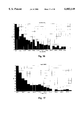
- FIG. 16 is a bar graph illustrating the harmonic range of the wave form illustrated in FIG. 14.
- FIG. 17 is a bar graph illustrating the harmonic range of the wave form illustrated in FIG. 15.
- a source of electrical energy preferably 110 or 220 volts in the United States
- An AC transformer designated generally by the reference letter B and labeled "power supply”
- power supply is electrically connected to the source A by a conventional power cord preferably rated to handle the input voltage of the source.
- the transformer varies the AC input voltage.
- the AC output is then passed through a single or series of bridge rectifiers C.
- the bridge rectifiers preferably provide either a full wave or half wave rectification of the wave form to a 60 or 120 cycles per second DC "positive" (i.e., above the reference line on a sinusoidal oscilloscope) wave form.
- the fully rectified wave form from the bridge rectifier(s) is then passed to the free ends of the coil designated generally by the reference letter D and labeled "DEVICE" for convenience.
- FIGS. 14 and 15 are graphs illustrating the half rectified and fully rectified, respectively, wave form produced by an eight hundred (800) winding embodiment of the present invention. The sample graphs were taken when the field strength within the confines of the embodiment tested was set to produce 7.5 amps of current.
- FIGS. 16 and 17 illustrate the harmonics corresponding to the wave forms of FIGS. 14 and 15 respectively.
- an embodiment of the device component of the present invention is designated generally by the reference number 600.
- the device frame 602 has been partially removed from FIG. 2 in order to show the permanent magnets 604 and the interiorly wrapped coil 606 in their preferred orientation.
- the coil winding 606 overlies the belt or annular layer of permanent magnets 604.
- a cover 610 is provided as a means of protecting and shielding the coil 606 during operation.
- thermocouple type which measure and indicate the coil temperature at various points.
- a preferred embodiment of the sensors are manufactured by Honeywell/Microswitch, Inc. and have model number SS94A2.
- Cover 610 can be a section of raceway cover which includes a cooperating tongue and groove snap connection 612 so that the cover may be removed to service the interior magnetic and coil components of the device.
- the air space 614 provides a means of convective heat transfer such that if an air flow in the air space 614 were created, the flow of air would have a tendency to cool the coil 606 and magnets 604 when they become heated after the coil 606 in energized in the manner described below.
- Cross-section line A--A which also serves as a vertical axis and horizontal line L, which serves as a horizontal axis, define the centroid of the interior channel 620 of the device.
- the gaps are provided so as to establish an open circuit condition so that the magnets themselves which are typically made of some metal do not become conductors. They are also believed to provide an oscillating or pulsating (i.e., changing) magnetic field as a function of time.
- Embodiment 700 includes a frame component 702.
- the side plates 704 cover the coil 706 as it is wrapped around the frame 702.
- One of the side plates has been removed from FIG. 2 for visual clarity of the coil 706 but the side plates 704 are preferably rigidly attached to the frame 702 in a working embodiment of the invention.
- thermocouple 704 Within the coil assembly 704 are a plurality of optional thermal sensors 708, of either the resistance or thermocouple type.
- the sensors are provided as a way of measuring the coil temperature at various points but do not affect the operation of the invention and its useful effect (i.e., angiogenesis and growth retardation of cancerous tumors).
- the preferred sensors are manufactured by Honeywell/Microswitch, Inc. and have model number SS94A2.
- a cover 710 is preferably rigidly secured to the frame. Attachment of the cover 710 to the frame 702 in the manner shown in the figures creates an air space 714 between the coil 706 and cover 710.
- the cover 710 may be snapped in place by a snap fit cooperation of the cover and the frame 712, or I the alternative the cover may be rigidly and securely attached by numerous others means of securement.
- the air space 714 allows for convective heat transfer from the coil 706 to the air within the air space 714. If an air flow is induced in the air space 714, the flow of air would have a s tendency to cool the coil 706 if it heats up during use.
- Cross-section line A--A of FIG. 4 which also serves as a vertical axis V intersects the horizontal axis H to define the interior centroid of the interior 716 of the device (FIG. 4).
- the magnetic lines of flux (not shown) are either to the left or to the right depending upon the frame of reference and the direction of current flow in the coil 706.
- FIGS. 6-9 illustrate a variety of device profiles in order to demonstrate the various configurations the coil 706 may have depending upon the width of the frame. As shown in FIGS. 6 and 9, the device may also multiple coils 706 in a stacked or adjacent relationship as denoted by the hypothetical dashed dividing line of those figures. An optimum coil thickness with respect to width is believed to help establish a more uniform minimum heat generation within the coil 706. It is contemplated that a coil cross-section like that shown in FIGS. 5-9 is optimum when the heat generated by the coil is at a minimum, and trial and error tests are expected to support this contention.
- the device and a cooling fan to provide air flow in the air space were connected to a standard 110 V or 220 V electrical service.
- the device was allowed to warm up through one ten-minute cycle (either positive or negative direction on current flow through coil component).
- the input current level was adjusted to ten amps during warm up and adjusted periodically to maintain a steady state ten (10) amperes supply current.
- the net result, depending upon a positive direction or negative direction of current flow was a magnetic field generated from the coil combined with the background magnetic field associated with the magnets.
- the first animal subjects i.e., laboratory mice of defined lineage
- the operator selected a positive or negative direction of current flow through the coil component, as appropriate.
- the ten (10) amperes of supply current was verified and adjusted if necessary. Periodic checks were performed to maintain ten (10) amps.
- mice Twenty (20) control mice and ten (10) mice in each of the treatment groups (i.e., positive and negative direction of current flow through the coil component). All of the mice were selected from a single lineage as good laboratory and experimental practices dictate. Each mouse was implanted with "16/C mammary adenocarcinoma" which is known to be a fast growing "aggressive" tumor model. The treatment began when the median tumor weights reached 100 mg. The treatments were terminated when the tumors became too large to allow the study to continue due to humane considerations (approximately two weeks of treatment).
- mice were sacrificed and the tumors were analyzed by preparing cross-sectional tumor slides from 3 mice per cage Group (i.e., 3 control, 3 positive, and 3 negative). For each tumor, the independent researcher examined 5 sites on the slide to quantitate it for CD31 staining--a known standard of cellular staining. The data is reported in EXAMPLE ONE below.
- Group 1 was the control group of tumor laden mice. They received no treatment but underwent the same standard care and handling as the other mice.
- Group 2 mice received exposure to fields generated by natural magnets only.
- Group 3 mice received exposure to electromagnetic fields only.
- Group 4 mice received exposure to a combined natural and magnetic field in an additive combination.
- “Additive” refers to the orientation of the magnetic field line of flux associated with the permanent magnets and electromagnetic field lines from the coil by itself such that corresponding fields overlapped.
- mice in this example were implanted with murine 16/C mammary adenocarcinoma tumor cells.
- a control group i.e., Group 1 of twenty mice was used. The mice in the control Group 1 were not treated with the inventive apparatus. Seven additional groups of ten mice each (Groups 2-8) were used for treatment.
- Animals in Group 2 were placed within the interior of the device once daily for 3 minutes per day for 12 days beginning on day 8 following tumor implantation with the DC current at 5 amps.
- Animals in Group 3 were placed within the interior of the device once daily for 10 minutes per day for 12 days beginning on day 8 following tumor implantation with the DC current at 5 amps.
- Animals in Group 4 were placed within the interior of the device once daily for 40 minutes per day for 12 days beginning on day 8 following tumor implantation with the DC current at 5 amps.
- Animals in Group 5 were placed within the interior of the device twice daily, at approximately 7 hour intervals) for 40 minutes for 12 days beginning on day 8 following tumor implantation with the DC current at 5 amps.
- Animals in Group 6 were placed within the interior of the device once daily for 10 minutes per day for 12 days beginning on day 8 ; following tumor implantation with the DC current at 7.5 amps.
- Animals in Group 7 were placed within the interior of the device once daily for 10 minutes per day for 12 days beginning on day 8 following tumor implantation with the DC current at 10 amps.
- Animals in Group 8 were placed within the interior of the device twice daily, at approximately 7 hour intervals, for 10 minutes per day for 12 days beginning on day 8 following tumor implantation S with the DC current at 10 amps.
- tumor weight was measured periodically and consistently to determine relative growth rates. Because of the shear volume of raw data relating to %CD31+angiogenesis assessment and tumor weight, graphical representation of the data will be used in this example instead of the tabular format used above. At the conclusion of the study the excised tumors were packed in the appropriate solution and frozen for further analysis.
- FIGS. 10-13 it is clearly shown the tumors of the control group (i.e., Group 1) mice exhibited a more angiogenesis than any of the treated groups. It also appears that the Group 6 treated mice exhibited the least angiogenesis of any group and thus the preferred method of exposure for this invention, as it relates to duration, current level and time of exposure is that which is associated with the Group 6 treatment protocol.
- FIG. 13 also shows the tumors of the mice of the treated groups grew more slowly and thus weighed less than the tumors of the control group (i.e., Group 1) mice.
Abstract
Description
______________________________________
% CD31 + Comparison by Slides (sample of preliminary data)
                                        MEAN  STD.
Sample     Site 1 Site 2 Site 3
                              Site 4
                                   Site 5
                                        %     DEV.
______________________________________
Cage Group 1-1
           28.88  21.17  24.04
                              18.27
                                   11.76
                                        20.82 6.40
Cage Group 1-2
           30.09  18.49  11.38
                              19.50
                                   18.32
                                        19.56 6.72
Cage Group 1-8
           15.27  13.39  30.01
                              33.18
                                   22.01
                                        22.77 8.74
Cage Group 2-2
           8.81   9.04   20.27
                              12.65
                                   12.08
                                        12.57 4.64
Cage Group 2-4
           11.53  12.07  16.07
                              21.23
                                   15.60
                                        15.23 4.49
Cage Group 2-5
           8.59   10.08  26.53
                              28.30
                                   18.50
                                        18.40 9.08
Cage Group 3-4
           8.07   6.98   14.63
                              7.06 10.01
                                        9.35  3.19
Cage Group 3-7
           8.62   21.48  9.85 4.24 10.05
                                        10.85 6.39
Cage Group 3-10
           24.28  4.69   4.62 10.41
                                   10.68
                                        10.94 8.02
______________________________________
______________________________________ CD31 + Comparison by Cage Groups Micro-vessel Density Assessed by CD31 Immunohistochemistry and Image Analysis Sample Treatment MEAN % STD. DEV.______________________________________ Group 1 None 21.05 1.62Group 2 Opposing 15.40 2.92Group 3 Additive 10.38 0.89 ______________________________________ "Additive" and "Opposing" refer to the orientation of the magnetic field line of flux associated with the permanent magnets and electromagnetic field lines from the coil by itself such that additive refers to an overlapping of the field lines while opposing refers to oppositely directed field lines.
______________________________________ CD31 + Comparison by Cage Groups Micro-vessel Density Assessed by CD31 Immunohistochemistry and Image Analysis Sample Treatment MEAN % STD. DEV.______________________________________ Group 1 None 22.94 4.15Group 2 Opposing 14.05 2.49Group 3 Additive 10.23 2.18 ______________________________________ "Additive" and "Opposing" refer to the orientation of the magnetic field line of flux associated with the permanent magnets and electromagnetic field lines from the coil by itself such that additive refers to an overlapping of the field lines while opposing refers to oppositely directed field lines.
______________________________________ Micro-vessel Density Assessed by CD31 Immunohistochemistry and Image Analysis Sample Treatment MEAN % STD. DEV.______________________________________ Group 1 None 18.67 2.28Group 2 Natural Field 17.37 2.80Group 3 electromagnetic field only 12.27 2.03Group 4 natural and 15.81 1.21 electromagnetic ______________________________________
Claims (49)
Priority Applications (7)
| Application Number | Priority Date | Filing Date | Title |
|---|---|---|---|
| US09/111,769 US6083149A (en) | 1997-10-22 | 1998-07-08 | Magnetic field device and method for inhibiting angiogenesis and retarding growth rates of tumors in mammals |
| DE69833045T DE69833045T2 (en) | 1998-07-08 | 1998-10-20 | INHIBITION OF ANGIOGENIC RELATED TUMOR GROWTH |
| AT98953754T ATE314089T1 (en) | 1998-07-08 | 1998-10-20 | INHIBITION OF ANGIOGENesis RELATED TUMOR GROWTH |
| AU11040/99A AU1104099A (en) | 1998-07-08 | 1998-10-20 | Retarding tumor angiogenesis related growth |
| PCT/US1998/022135 WO2000002585A1 (en) | 1998-07-08 | 1998-10-20 | Retarding tumor angiogenesis related growth |
| EP98953754A EP1094838B1 (en) | 1998-07-08 | 1998-10-20 | Retarding tumor angiogenesis related growth |
| US09/556,450 US6443882B1 (en) | 1998-07-08 | 2000-04-24 | Apparatus and method for creating a biologically useful magnetic field |
Applications Claiming Priority (2)
| Application Number | Priority Date | Filing Date | Title |
|---|---|---|---|
| US08/955,604 US6007476A (en) | 1997-10-22 | 1997-10-22 | Non-particle, non-photonic device and method for affecting angiogenesis |
| US09/111,769 US6083149A (en) | 1997-10-22 | 1998-07-08 | Magnetic field device and method for inhibiting angiogenesis and retarding growth rates of tumors in mammals |
Related Parent Applications (1)
| Application Number | Title | Priority Date | Filing Date |
|---|---|---|---|
| US08/955,604 Continuation-In-Part US6007476A (en) | 1997-10-22 | 1997-10-22 | Non-particle, non-photonic device and method for affecting angiogenesis |
Related Child Applications (1)
| Application Number | Title | Priority Date | Filing Date |
|---|---|---|---|
| US09/556,450 Continuation-In-Part US6443882B1 (en) | 1998-07-08 | 2000-04-24 | Apparatus and method for creating a biologically useful magnetic field |
Publications (1)
| Publication Number | Publication Date |
|---|---|
| US6083149A true US6083149A (en) | 2000-07-04 |
Family
ID=22340351
Family Applications (2)
| Application Number | Title | Priority Date | Filing Date |
|---|---|---|---|
| US09/111,769 Expired - Fee Related US6083149A (en) | 1997-10-22 | 1998-07-08 | Magnetic field device and method for inhibiting angiogenesis and retarding growth rates of tumors in mammals |
| US09/556,450 Expired - Lifetime US6443882B1 (en) | 1998-07-08 | 2000-04-24 | Apparatus and method for creating a biologically useful magnetic field |
Family Applications After (1)
| Application Number | Title | Priority Date | Filing Date |
|---|---|---|---|
| US09/556,450 Expired - Lifetime US6443882B1 (en) | 1998-07-08 | 2000-04-24 | Apparatus and method for creating a biologically useful magnetic field |
Country Status (6)
| Country | Link |
|---|---|
| US (2) | US6083149A (en) |
| EP (1) | EP1094838B1 (en) |
| AT (1) | ATE314089T1 (en) |
| AU (1) | AU1104099A (en) |
| DE (1) | DE69833045T2 (en) |
| WO (1) | WO2000002585A1 (en) |
Cited By (40)
| Publication number | Priority date | Publication date | Assignee | Title |
|---|---|---|---|---|
| US6235251B1 (en) * | 1999-07-26 | 2001-05-22 | James G. Davidson | System and method for treating cells using electromagnetic-based radiation |
| WO2001062336A1 (en) * | 2000-02-23 | 2001-08-30 | The Trustees Of The University Of Pennsylvania | Regulation of genes via application of specific and selective electrical and electromagnetic signals |
| US6443882B1 (en) * | 1998-07-08 | 2002-09-03 | Emf Therapeutics, Inc. | Apparatus and method for creating a biologically useful magnetic field |
| US6527694B1 (en) * | 1999-09-30 | 2003-03-04 | Nihon Kohden Corporation | Air-cooling device for coil for urinary incontinence treatment |
| US20040006373A1 (en) * | 2000-02-23 | 2004-01-08 | The Trustees Of The University Of Pennsylvania | Method and device for treating osteoarthritis, cartilage disease, defects and injuries in the human knee |
| US6679827B2 (en) | 2001-10-11 | 2004-01-20 | Robert E. Sandstrom | Magnetic field enhancement of tumor treatment |
| US20040073260A1 (en) * | 2000-02-23 | 2004-04-15 | Woodcock Washburn Llp | Regulation of type II collagen gene expression using specific and selective electrical and electromagnetic signals |
| US20040138709A1 (en) * | 2000-02-23 | 2004-07-15 | Brighton Carl T. | Regulation of matrix metalloproteinase gene expression using specific and selective electrical and electromagnetic signals |
| US20050010264A1 (en) * | 2000-02-23 | 2005-01-13 | Brighton Carl T. | Portable electrotherapy device for treating osteoarthritis and other diseases, defects and injuries of the knee joint |
| US20050125045A1 (en) * | 2001-07-03 | 2005-06-09 | Brighton Carl T. | Device and method for electrically inducing osteogenesis in the spine |
| US20050177203A1 (en) * | 2003-11-14 | 2005-08-11 | Brighton Carl T. | Method and device for treating osteoarthritis and cartilage disease, defects, and injuries in the human hip |
| US20050228462A1 (en) * | 2001-12-21 | 2005-10-13 | Brighton Carl T | Device for treating osteoporosis, hip and spine fractures and fusions with electric fields |
| US20050267355A1 (en) * | 2004-05-27 | 2005-12-01 | Parker Richard F | Method and apparatus for generating a therapeutic magetic field |
| US20060235473A1 (en) * | 2000-02-23 | 2006-10-19 | The Trustees Of The Univeristy Of Pennsylvania | Regulation of transforming growth factor-beta (TGF-beta) gene expression in living cells via the application of specific and selective electric and electromagnetic fields |
| US20070015951A1 (en) * | 2005-07-14 | 2007-01-18 | Culhane Jeffrey J | Bone growth stimulator |
| US20070078292A1 (en) * | 2005-10-05 | 2007-04-05 | Electromagnetic Resources, Inc. | Electromagnetic fields for systemic effect in therapy |
| US20070299472A1 (en) * | 2000-02-23 | 2007-12-27 | The Trustees Of The University Of Pennsylvania | System and Method of Up-Regulating Bone Morphogenetic Proteins (Bmp) Gene Expression in Bone Cells Via the Application of Fields Generated by Specific and Selective Electric and Electromagnetic Signals |
| US20080097141A1 (en) * | 2006-10-19 | 2008-04-24 | Stanley Kolt | K-ring electromagnetic treatment apparatus, system and method for tumors, arthritis and other ailments |
| US7374916B2 (en) | 2000-02-23 | 2008-05-20 | The Trustees Of The University Of Pennsylvania | Regulation of aggrecan gene expression using specific and selective electrical and electromagnetic signals |
| US20080140155A1 (en) * | 2005-03-07 | 2008-06-12 | Pilla Arthur A | Excessive fibrous capsule formation and capsular contracture apparatus and method for using same |
| US20080215116A1 (en) * | 2000-02-23 | 2008-09-04 | The Trustees Of The University Of Pennsylvania | Regulation of fibroblastic growth factor-2 (fgf-2) gene expression in living cells with the application of specific and selective electric and electromagnetic fields |
| US20100210893A1 (en) * | 2003-12-05 | 2010-08-19 | Pilla Arthur A | Apparatus and method for electromagnetic treatment of plant, animal, and human tissue, organs, cells, and molecules |
| US20110077452A1 (en) * | 2006-10-19 | 2011-03-31 | Stanley Kolt | K-ring electromagnetic treatment apparatus, system and method for tumors, arthritis and other ailments |
| US20110112352A1 (en) * | 2003-12-05 | 2011-05-12 | Pilla Arthur A | Apparatus and method for electromagnetic treatment |
| US20110207989A1 (en) * | 2003-12-05 | 2011-08-25 | Pilla Arthur A | Devices and method for treatment of degenerative joint diseases with electromagnetic fields |
| US8313908B2 (en) | 2000-02-23 | 2012-11-20 | The Trustees Of The University Of Pennsylvania | Regulation of stem cell gene production with specific and selective electric and electromagnetic fields |
| US8343027B1 (en) | 2012-01-30 | 2013-01-01 | Ivivi Health Sciences, Llc | Methods and devices for providing electromagnetic treatment in the presence of a metal-containing implant |
| US8415123B2 (en) | 2004-04-19 | 2013-04-09 | Ivivi Health Sciences, Llc | Electromagnetic treatment apparatus and method for angiogenesis modulation of living tissues and cells |
| US9320913B2 (en) | 2014-04-16 | 2016-04-26 | Rio Grande Neurosciences, Inc. | Two-part pulsed electromagnetic field applicator for application of therapeutic energy |
| US9415233B2 (en) | 2003-12-05 | 2016-08-16 | Rio Grande Neurosciences, Inc. | Apparatus and method for electromagnetic treatment of neurological pain |
| US9427598B2 (en) | 2010-10-01 | 2016-08-30 | Rio Grande Neurosciences, Inc. | Method and apparatus for electromagnetic treatment of head, cerebral and neural injury in animals and humans |
| US9433797B2 (en) | 2003-12-05 | 2016-09-06 | Rio Grande Neurosciences, Inc. | Apparatus and method for electromagnetic treatment of neurodegenerative conditions |
| US9440089B2 (en) | 2003-12-05 | 2016-09-13 | Rio Grande Neurosciences, Inc. | Apparatus and method for electromagnetic treatment of neurological injury or condition caused by a stroke |
| CN106621050A (en) * | 2017-02-07 | 2017-05-10 | 浙江大学 | Power frequency electromagnetic field generating device having tumor inhibiting effect and loading method |
| US9656096B2 (en) | 2003-12-05 | 2017-05-23 | Rio Grande Neurosciences, Inc. | Method and apparatus for electromagnetic enhancement of biochemical signaling pathways for therapeutics and prophylaxis in plants, animals and humans |
| TWI584777B (en) * | 2014-08-22 | 2017-06-01 | 國立成功大學 | Flexible deep magnetic field generating apparatus |
| US10350428B2 (en) | 2014-11-04 | 2019-07-16 | Endonovo Therapetics, Inc. | Method and apparatus for electromagnetic treatment of living systems |
| US10806942B2 (en) | 2016-11-10 | 2020-10-20 | Qoravita LLC | System and method for applying a low frequency magnetic field to biological tissues |
| US10967194B2 (en) | 2018-05-02 | 2021-04-06 | Shealy-Sorin Wellness, Llc | Pulsed electromagnetic field device and methods of use |
| US11752357B2 (en) * | 2017-11-17 | 2023-09-12 | Hofmeir Magnetics Limited | Pulsed electromagnetic field therapy device |
Families Citing this family (5)
| Publication number | Priority date | Publication date | Assignee | Title |
|---|---|---|---|---|
| US20020188336A1 (en) * | 2001-06-08 | 2002-12-12 | Bothe Loncar Goetz Friedrich | Method of enhancing and regularizing specific autonomic nervous and endocrine functions through the continuous and discriminate thermal or electric stimulation of specific discrete skin areas |
| GB0405552D0 (en) * | 2004-03-12 | 2004-04-21 | Magnet Attraction Ltd | Methods for the targetted delivery of biological molecules |
| US7581403B2 (en) * | 2005-04-15 | 2009-09-01 | Deeks Daniel H | Energy storage arrangement |
| US20070083237A1 (en) * | 2005-10-12 | 2007-04-12 | Teruel Elberto B | Magnetic therapeutic device and method of using the same |
| AU2008200129B2 (en) * | 2008-01-10 | 2012-10-04 | Daniel H Deeks | Energy storage arrangement |
Citations (82)
| Publication number | Priority date | Publication date | Assignee | Title |
|---|---|---|---|---|
| US32947A (en) * | 1861-07-30 | Machine for bending fifth-wheels fob | ||
| US96044A (en) * | 1869-10-19 | Improvement in galvanic apparatus | ||
| US703989A (en) * | 1900-05-08 | 1902-07-08 | Max Wyler | Magneto-therapeutic apparatus. |
| US770433A (en) * | 1904-09-20 | Thermal inductor | ||
| US781448A (en) * | 1904-10-29 | 1905-01-31 | John Mcintyre | Electromagnetic apparatus. |
| US2102790A (en) * | 1934-08-20 | 1937-12-21 | Howard B Drollinger | Therapeutic apparatus |
| US3570476A (en) * | 1968-11-18 | 1971-03-16 | David Paul Gregg | Magnetostrictive medical instrument |
| DE2353959A1 (en) * | 1973-10-27 | 1975-05-07 | Harry Graf | Body magneto-energetic process influencing appts. - has magnetic coil wound without core about tube to receive body |
| US3890953A (en) * | 1971-04-06 | 1975-06-24 | Werner Kraus | Electrical apparatus generating a low frequency, alternating magnetic field for promoting the growth of bone and other body tissues |
| US3915151A (en) * | 1973-03-23 | 1975-10-28 | Werner Kraus | Apparatus for promoting healing processes |
| US4066065A (en) * | 1974-07-04 | 1978-01-03 | Werner Kraus | Coil structure for electromagnetic therapy |
| US4134395A (en) * | 1976-12-29 | 1979-01-16 | Biomagnetics International, Inc. | Method of using magnetic fields to conduct a screening diagnostic examination |
| US4233965A (en) * | 1978-01-16 | 1980-11-18 | Cas Products, Inc. | Method and apparatus for the therapeutic treatment of living tissue |
| US4303636A (en) * | 1974-08-20 | 1981-12-01 | Gordon Robert T | Cancer treatment |
| EP0048451A1 (en) * | 1980-09-24 | 1982-03-31 | 121873 Canada Inc. | Electro-magnetic therapeutic system and method |
| US4402309A (en) * | 1981-10-22 | 1983-09-06 | Donald L. Morton & Associates | Therapeutic magnetic electrode |
| EP0181053A2 (en) * | 1984-09-12 | 1986-05-14 | Irt, Inc. | Pulse electro-magnetic field therapy device with auto biased circuit and method for use |
| US4622952A (en) * | 1983-01-13 | 1986-11-18 | Gordon Robert T | Cancer treatment method |
| US4626792A (en) * | 1984-01-10 | 1986-12-02 | Cornell Research Foundation, Inc. | Pure crystal exciton laser amplifier and method of operation |
| US4641633A (en) * | 1982-03-16 | 1987-02-10 | Delgado Jose M R | Electronic system for the activation, inhibition and/or modification of the development and functioning of cells, organs and organisms of living beings |
| US4674482A (en) * | 1984-09-12 | 1987-06-23 | Irt, Inc. | Pulse electro-magnetic field therapy device with auto bias circuit |
| US4765310A (en) * | 1985-11-01 | 1988-08-23 | Dynatens Research Corporation | Electrical and magnetic pain treatment device |
| US4818697A (en) * | 1986-10-27 | 1989-04-04 | Life Resonances, Inc. | Techniques for enhancing the permeability of ions through membranes |
| US4838850A (en) * | 1980-10-03 | 1989-06-13 | Henning Rosengart | Electromedical treatment apparatus |
| USRE32947E (en) | 1980-09-30 | 1989-06-13 | Baptist Medical Center Of Oklahoma, Inc. | Magnetic transcutaneous mount for external device of an associated implant |
| US4889526A (en) * | 1984-08-27 | 1989-12-26 | Magtech Laboratories, Inc. | Non-invasive method and apparatus for modulating brain signals through an external magnetic or electric field to reduce pain |
| EP0371504A2 (en) * | 1988-11-30 | 1990-06-06 | Jerry I. Jacobson | Therapeutic treatment of mammals |
| US4932951A (en) * | 1988-03-23 | 1990-06-12 | Life Resonances, Inc. | Method and apparatus for controlling tissue growth and an applied fluctuating magnetic field |
| US4940453A (en) * | 1987-01-28 | 1990-07-10 | Cadwell Industries, Inc. | Method and apparatus for magnetically stimulating neurons |
| US4994015A (en) * | 1987-09-14 | 1991-02-19 | Cadwell Industries, Inc. | Magnetic stimulator coils |
| US4993413A (en) * | 1988-09-22 | 1991-02-19 | The Research Foundation Of State University Of New York | Method and apparatus for inducing a current and voltage in living tissue |
| US5000178A (en) * | 1986-05-23 | 1991-03-19 | Lti Biomedical, Inc. | Shielded electromagnetic transducer |
| US5010897A (en) * | 1989-04-26 | 1991-04-30 | Leveen Harry H | Apparatus for deep heating of cancer |
| US5014699A (en) * | 1986-05-23 | 1991-05-14 | Trustees Of The University Of Pennsylvania | Electromagnetic method and apparatus for healing living tissue |
| US5030196A (en) * | 1980-04-23 | 1991-07-09 | Inoue-Japax Research Incorporated | Magnetic treatment device |
| US5045050A (en) * | 1989-11-15 | 1991-09-03 | Life Resonances | Method and apparatus for the treatment of cancer |
| US5047005A (en) * | 1987-01-28 | 1991-09-10 | Cadwell Industries, Inc. | Method and apparatus for magnetically stimulating neurons |
| US5061234A (en) * | 1989-09-25 | 1991-10-29 | Corteks, Inc. | Magnetic neural stimulator for neurophysiology |
| US5066272A (en) * | 1990-06-29 | 1991-11-19 | The Johns Hopkins University | Magnetic nerve stimulator |
| US5067940A (en) * | 1988-03-23 | 1991-11-26 | Life Resonances, Inc. | Method and apparatus for controlling the growth of cartilage |
| US5078674A (en) * | 1989-02-10 | 1992-01-07 | Cadwll Industries, Inc. | Magnetic stimulator coils |
| US5077934A (en) * | 1989-09-22 | 1992-01-07 | Life Resonances, Inc. | Method and apparatus for controlling plant growth |
| US5084003A (en) * | 1989-11-24 | 1992-01-28 | Dragan Susic | Magnetic massage therapy device |
| US5085627A (en) * | 1988-08-18 | 1992-02-04 | Mezhotraslevoi Nauchno-Tekhnichesky Komplex "Mikrokhirurgia Glaza" | Method for treatment of diseases of the optic tract |
| US5085626A (en) * | 1988-12-06 | 1992-02-04 | Alsthom International S.A. | Physiotherapeutic apparatus provided for producing a magnetic field to be used as a therapeutic means |
| US5087336A (en) * | 1989-01-09 | 1992-02-11 | Life Resonances, Inc. | Methods and apparatus for regulating transmembrane ion movement utilizing selective harmonic frequencies and simultaneous multiple ion regulation |
| US5088976A (en) * | 1988-03-23 | 1992-02-18 | Life Resonances, Inc. | Deformable magnetic field aiding coils for use in controlling tissue growth |
| US5090423A (en) * | 1988-02-18 | 1992-02-25 | Omron Corporation | Local heating apparatus and cavity resonator for local heating |
| US5100373A (en) * | 1989-01-09 | 1992-03-31 | Life Resonances, Inc. | Techniques for controlling osteoporosis using non-invasive magnetic fields |
| US5106361A (en) * | 1988-03-23 | 1992-04-21 | Life Resonances, Inc. | Method and apparatus for controlling the growth of non-osseous non-cartilaginous solid connective tissue |
| US5116304A (en) * | 1987-01-28 | 1992-05-26 | Cadwell Industries, Inc. | Magnetic stimulator with skullcap-shaped coil |
| US5123898A (en) * | 1988-03-23 | 1992-06-23 | Life Resonances, Inc. | Method and apparatus for controlling tissue growth with an applied fluctuating magnetic field |
| US5131904A (en) * | 1990-05-04 | 1992-07-21 | Richard Markoll | Treatment of arthritis with magnetic field therapy and apparatus therefor |
| US5143588A (en) * | 1986-10-27 | 1992-09-01 | Life Resonances, Inc. | Techniques for enhancing the permeability of ions through membranes |
| US5156587A (en) * | 1983-09-01 | 1992-10-20 | Montone Liber J | Method for treating malignant cells |
| US5160591A (en) * | 1986-10-27 | 1992-11-03 | Life Resonances, Inc. | Methods and apparatus for regulating transmembrane ion movement utilizing selective harmonic frequencies and simultaneous multiple ion regulation |
| US5183456A (en) * | 1989-11-15 | 1993-02-02 | Life Resonances, Inc. | Method and apparatus for the treatment of cancer |
| US5195940A (en) * | 1991-06-20 | 1993-03-23 | Iatromed, Inc. | Method for increased production of growth factor in living tissue using an applied fluctuating magnetic field |
| US5211622A (en) * | 1989-11-15 | 1993-05-18 | Life Resonances, Inc. | Method and apparatus for the treatment of cancer |
| US5215642A (en) * | 1986-10-27 | 1993-06-01 | Life Resonances, Inc. | Improved method and apparatus for regulating transmembrane ion movement |
| US5215633A (en) * | 1986-10-27 | 1993-06-01 | Life Resonances, Inc. | Techniques for enhancing the permeability of ions through membranes |
| US5224922A (en) * | 1988-05-19 | 1993-07-06 | Kurtz Warren H | Quasistatic biological cell and tissue modifier |
| US5267939A (en) * | 1989-01-09 | 1993-12-07 | Life Resonances, Inc. | Techniques for controlling osteoporosis using non-invasive magnetic fields |
| US5269745A (en) * | 1988-03-23 | 1993-12-14 | Life Resonances, Inc. | Method and apparatus for controlling tissue growth with an applied fluctuating magnetic field |
| US5269746A (en) * | 1982-12-20 | 1993-12-14 | Jacobson Jerry I | Therapeutic treatment of mammals for epilepsy and Parkinson's disease |
| US5290409A (en) * | 1986-10-27 | 1994-03-01 | Life Resonances, Inc. | Methods and apparatus for regulating transmembrane ion movement utilizing selective harmonic frequencies and simultaneous multiple ion regulation |
| US5312321A (en) * | 1986-11-21 | 1994-05-17 | Holcomb Technology, Inc. | Method and apparatus for suppressing neuron action potential firings |
| US5314400A (en) * | 1988-04-25 | 1994-05-24 | Tsyb Anatoly F | Device for magnotherapy |
| US5318561A (en) * | 1988-03-23 | 1994-06-07 | Life Resonances Inc. | Deformable magnetic field aiding coils for use in controlling tissue growth |
| US5344384A (en) * | 1992-12-11 | 1994-09-06 | Electromagnetic Bracing Systems, Inc. | Magnetotherapy apparatus |
| US5357958A (en) * | 1993-03-18 | 1994-10-25 | The Regents Of The University Of California | Interventional MRI system and RF coils therefore |
| US5366435A (en) * | 1982-12-20 | 1994-11-22 | Jacobson Jerry I | Therapeutic treatment of mammals |
| US5368544A (en) * | 1990-10-04 | 1994-11-29 | Tn Bio-Electronics Pty. Ltd. | Treatment of living bodies |
| US5415617A (en) * | 1990-05-29 | 1995-05-16 | Kraus; Werner | Applicator coil for magnetic field therapy |
| US5441495A (en) * | 1989-08-17 | 1995-08-15 | Life Resonances, Inc. | Electromagnetic treatment therapy for stroke victim |
| US5476438A (en) * | 1993-03-11 | 1995-12-19 | Zentralinstitut Fur Biomedizinische Technik Universitat Ulm | Method and apparatus for neuromagnetic stimulation |
| US5518495A (en) * | 1994-08-29 | 1996-05-21 | Magnetherapy, Inc. | Magnetic field therapy apparatus |
| US5525949A (en) * | 1991-06-19 | 1996-06-11 | Oxford Instruments (Uk) Ltd. | Energy storage device |
| US5541563A (en) * | 1995-01-11 | 1996-07-30 | The United States Of America As Represented By The Secretary Of The Army | Magnet iron structure |
| DE19600744A1 (en) * | 1996-01-11 | 1997-07-17 | Werner Alois Prof Dipl Kaiser | Magnetic substance for local hyperthermic treatment of mainly small tumors |
| US5658234A (en) * | 1995-07-24 | 1997-08-19 | J. D. Technologies, Inc. | Method for treating tumors |
| US5880661A (en) * | 1996-04-01 | 1999-03-09 | Emf Therapeutics, Inc. | Complex magnetic field generating device |
Family Cites Families (3)
| Publication number | Priority date | Publication date | Assignee | Title |
|---|---|---|---|---|
| US5478303A (en) * | 1992-09-18 | 1995-12-26 | Foley-Nolan; Darragh | Electromagnetic apparatus for use in therapy |
| US6083149A (en) * | 1997-10-22 | 2000-07-04 | Emf Therapeutics, Inc. | Magnetic field device and method for inhibiting angiogenesis and retarding growth rates of tumors in mammals |
| US6149577A (en) * | 1999-03-18 | 2000-11-21 | Emf Therapeutics, Inc. | Apparatus and method for creating a substantially contained, finite magnetic field useful for relieving the symptoms pain and discomfort associated with degenerative diseases and disorders in mammals |
-
1998
- 1998-07-08 US US09/111,769 patent/US6083149A/en not_active Expired - Fee Related
- 1998-10-20 AT AT98953754T patent/ATE314089T1/en not_active IP Right Cessation
- 1998-10-20 EP EP98953754A patent/EP1094838B1/en not_active Expired - Lifetime
- 1998-10-20 WO PCT/US1998/022135 patent/WO2000002585A1/en active IP Right Grant
- 1998-10-20 AU AU11040/99A patent/AU1104099A/en not_active Abandoned
- 1998-10-20 DE DE69833045T patent/DE69833045T2/en not_active Expired - Fee Related
-
2000
- 2000-04-24 US US09/556,450 patent/US6443882B1/en not_active Expired - Lifetime
Patent Citations (92)
| Publication number | Priority date | Publication date | Assignee | Title |
|---|---|---|---|---|
| US32947A (en) * | 1861-07-30 | Machine for bending fifth-wheels fob | ||
| US96044A (en) * | 1869-10-19 | Improvement in galvanic apparatus | ||
| US770433A (en) * | 1904-09-20 | Thermal inductor | ||
| US703989A (en) * | 1900-05-08 | 1902-07-08 | Max Wyler | Magneto-therapeutic apparatus. |
| US781448A (en) * | 1904-10-29 | 1905-01-31 | John Mcintyre | Electromagnetic apparatus. |
| US2102790A (en) * | 1934-08-20 | 1937-12-21 | Howard B Drollinger | Therapeutic apparatus |
| US3570476A (en) * | 1968-11-18 | 1971-03-16 | David Paul Gregg | Magnetostrictive medical instrument |
| US3890953A (en) * | 1971-04-06 | 1975-06-24 | Werner Kraus | Electrical apparatus generating a low frequency, alternating magnetic field for promoting the growth of bone and other body tissues |
| US3915151A (en) * | 1973-03-23 | 1975-10-28 | Werner Kraus | Apparatus for promoting healing processes |
| DE2353959A1 (en) * | 1973-10-27 | 1975-05-07 | Harry Graf | Body magneto-energetic process influencing appts. - has magnetic coil wound without core about tube to receive body |
| US4066065A (en) * | 1974-07-04 | 1978-01-03 | Werner Kraus | Coil structure for electromagnetic therapy |
| US4303636A (en) * | 1974-08-20 | 1981-12-01 | Gordon Robert T | Cancer treatment |
| US4134395A (en) * | 1976-12-29 | 1979-01-16 | Biomagnetics International, Inc. | Method of using magnetic fields to conduct a screening diagnostic examination |
| US4233965A (en) * | 1978-01-16 | 1980-11-18 | Cas Products, Inc. | Method and apparatus for the therapeutic treatment of living tissue |
| US5030196A (en) * | 1980-04-23 | 1991-07-09 | Inoue-Japax Research Incorporated | Magnetic treatment device |
| EP0048451A1 (en) * | 1980-09-24 | 1982-03-31 | 121873 Canada Inc. | Electro-magnetic therapeutic system and method |
| USRE32947E (en) | 1980-09-30 | 1989-06-13 | Baptist Medical Center Of Oklahoma, Inc. | Magnetic transcutaneous mount for external device of an associated implant |
| US4838850A (en) * | 1980-10-03 | 1989-06-13 | Henning Rosengart | Electromedical treatment apparatus |
| US4402309A (en) * | 1981-10-22 | 1983-09-06 | Donald L. Morton & Associates | Therapeutic magnetic electrode |
| US4641633A (en) * | 1982-03-16 | 1987-02-10 | Delgado Jose M R | Electronic system for the activation, inhibition and/or modification of the development and functioning of cells, organs and organisms of living beings |
| US5269746A (en) * | 1982-12-20 | 1993-12-14 | Jacobson Jerry I | Therapeutic treatment of mammals for epilepsy and Parkinson's disease |
| US5366435A (en) * | 1982-12-20 | 1994-11-22 | Jacobson Jerry I | Therapeutic treatment of mammals |
| US4622952A (en) * | 1983-01-13 | 1986-11-18 | Gordon Robert T | Cancer treatment method |
| US5156587A (en) * | 1983-09-01 | 1992-10-20 | Montone Liber J | Method for treating malignant cells |
| US4626792A (en) * | 1984-01-10 | 1986-12-02 | Cornell Research Foundation, Inc. | Pure crystal exciton laser amplifier and method of operation |
| US4889526A (en) * | 1984-08-27 | 1989-12-26 | Magtech Laboratories, Inc. | Non-invasive method and apparatus for modulating brain signals through an external magnetic or electric field to reduce pain |
| EP0181053A2 (en) * | 1984-09-12 | 1986-05-14 | Irt, Inc. | Pulse electro-magnetic field therapy device with auto biased circuit and method for use |
| US4674482A (en) * | 1984-09-12 | 1987-06-23 | Irt, Inc. | Pulse electro-magnetic field therapy device with auto bias circuit |
| US4765310A (en) * | 1985-11-01 | 1988-08-23 | Dynatens Research Corporation | Electrical and magnetic pain treatment device |
| US5014699A (en) * | 1986-05-23 | 1991-05-14 | Trustees Of The University Of Pennsylvania | Electromagnetic method and apparatus for healing living tissue |
| US5000178A (en) * | 1986-05-23 | 1991-03-19 | Lti Biomedical, Inc. | Shielded electromagnetic transducer |
| US5215642A (en) * | 1986-10-27 | 1993-06-01 | Life Resonances, Inc. | Improved method and apparatus for regulating transmembrane ion movement |
| US5312534A (en) * | 1986-10-27 | 1994-05-17 | Liboff Abraham R | Techniques for enhancing the permeability of ions through membranes |
| US5143588A (en) * | 1986-10-27 | 1992-09-01 | Life Resonances, Inc. | Techniques for enhancing the permeability of ions through membranes |
| US4818697A (en) * | 1986-10-27 | 1989-04-04 | Life Resonances, Inc. | Techniques for enhancing the permeability of ions through membranes |
| US5290409A (en) * | 1986-10-27 | 1994-03-01 | Life Resonances, Inc. | Methods and apparatus for regulating transmembrane ion movement utilizing selective harmonic frequencies and simultaneous multiple ion regulation |
| US5059298A (en) * | 1986-10-27 | 1991-10-22 | Life Resonances, Inc. | Method and apparatus for regulating transmembrane ion movement |
| US5160591A (en) * | 1986-10-27 | 1992-11-03 | Life Resonances, Inc. | Methods and apparatus for regulating transmembrane ion movement utilizing selective harmonic frequencies and simultaneous multiple ion regulation |
| US5215633A (en) * | 1986-10-27 | 1993-06-01 | Life Resonances, Inc. | Techniques for enhancing the permeability of ions through membranes |
| US5312321A (en) * | 1986-11-21 | 1994-05-17 | Holcomb Technology, Inc. | Method and apparatus for suppressing neuron action potential firings |
| US5047005A (en) * | 1987-01-28 | 1991-09-10 | Cadwell Industries, Inc. | Method and apparatus for magnetically stimulating neurons |
| US4940453A (en) * | 1987-01-28 | 1990-07-10 | Cadwell Industries, Inc. | Method and apparatus for magnetically stimulating neurons |
| US5116304A (en) * | 1987-01-28 | 1992-05-26 | Cadwell Industries, Inc. | Magnetic stimulator with skullcap-shaped coil |
| US4994015A (en) * | 1987-09-14 | 1991-02-19 | Cadwell Industries, Inc. | Magnetic stimulator coils |
| US5090423A (en) * | 1988-02-18 | 1992-02-25 | Omron Corporation | Local heating apparatus and cavity resonator for local heating |
| US5318561A (en) * | 1988-03-23 | 1994-06-07 | Life Resonances Inc. | Deformable magnetic field aiding coils for use in controlling tissue growth |
| US5458558A (en) * | 1988-03-23 | 1995-10-17 | Life Resonances, Inc. | Method for controlling tissue growth with an applied fluctuating magnetic field |
| US5088976A (en) * | 1988-03-23 | 1992-02-18 | Life Resonances, Inc. | Deformable magnetic field aiding coils for use in controlling tissue growth |
| US5269745A (en) * | 1988-03-23 | 1993-12-14 | Life Resonances, Inc. | Method and apparatus for controlling tissue growth with an applied fluctuating magnetic field |
| US5067940A (en) * | 1988-03-23 | 1991-11-26 | Life Resonances, Inc. | Method and apparatus for controlling the growth of cartilage |
| US5106361A (en) * | 1988-03-23 | 1992-04-21 | Life Resonances, Inc. | Method and apparatus for controlling the growth of non-osseous non-cartilaginous solid connective tissue |
| US4932951A (en) * | 1988-03-23 | 1990-06-12 | Life Resonances, Inc. | Method and apparatus for controlling tissue growth and an applied fluctuating magnetic field |
| US5123898A (en) * | 1988-03-23 | 1992-06-23 | Life Resonances, Inc. | Method and apparatus for controlling tissue growth with an applied fluctuating magnetic field |
| US5518496A (en) * | 1988-03-23 | 1996-05-21 | Life Resonances, Inc. | Deformable magnetic field aiding coils for use in controlling tissue growth |
| US5314400A (en) * | 1988-04-25 | 1994-05-24 | Tsyb Anatoly F | Device for magnotherapy |
| US5224922A (en) * | 1988-05-19 | 1993-07-06 | Kurtz Warren H | Quasistatic biological cell and tissue modifier |
| US5085627A (en) * | 1988-08-18 | 1992-02-04 | Mezhotraslevoi Nauchno-Tekhnichesky Komplex "Mikrokhirurgia Glaza" | Method for treatment of diseases of the optic tract |
| US4993413A (en) * | 1988-09-22 | 1991-02-19 | The Research Foundation Of State University Of New York | Method and apparatus for inducing a current and voltage in living tissue |
| EP0371504A2 (en) * | 1988-11-30 | 1990-06-06 | Jerry I. Jacobson | Therapeutic treatment of mammals |
| US5085626A (en) * | 1988-12-06 | 1992-02-04 | Alsthom International S.A. | Physiotherapeutic apparatus provided for producing a magnetic field to be used as a therapeutic means |
| US5087336A (en) * | 1989-01-09 | 1992-02-11 | Life Resonances, Inc. | Methods and apparatus for regulating transmembrane ion movement utilizing selective harmonic frequencies and simultaneous multiple ion regulation |
| US5100373A (en) * | 1989-01-09 | 1992-03-31 | Life Resonances, Inc. | Techniques for controlling osteoporosis using non-invasive magnetic fields |
| US5267939A (en) * | 1989-01-09 | 1993-12-07 | Life Resonances, Inc. | Techniques for controlling osteoporosis using non-invasive magnetic fields |
| US5078674A (en) * | 1989-02-10 | 1992-01-07 | Cadwll Industries, Inc. | Magnetic stimulator coils |
| US5010897A (en) * | 1989-04-26 | 1991-04-30 | Leveen Harry H | Apparatus for deep heating of cancer |
| US5441495A (en) * | 1989-08-17 | 1995-08-15 | Life Resonances, Inc. | Electromagnetic treatment therapy for stroke victim |
| US5077934A (en) * | 1989-09-22 | 1992-01-07 | Life Resonances, Inc. | Method and apparatus for controlling plant growth |
| US5061234A (en) * | 1989-09-25 | 1991-10-29 | Corteks, Inc. | Magnetic neural stimulator for neurophysiology |
| US5437600A (en) * | 1989-11-15 | 1995-08-01 | Life Resonances, Inc. | Method and apparatus for the treatment of cancer |
| US5045050A (en) * | 1989-11-15 | 1991-09-03 | Life Resonances | Method and apparatus for the treatment of cancer |
| US5183456A (en) * | 1989-11-15 | 1993-02-02 | Life Resonances, Inc. | Method and apparatus for the treatment of cancer |
| US5211622A (en) * | 1989-11-15 | 1993-05-18 | Life Resonances, Inc. | Method and apparatus for the treatment of cancer |
| US5084003A (en) * | 1989-11-24 | 1992-01-28 | Dragan Susic | Magnetic massage therapy device |
| US5453073A (en) * | 1990-05-04 | 1995-09-26 | Bio Magnetic Therapy Sys Inc | Apparatus for treatment of diseased body organs with magnetic field therapy |
| US5131904A (en) * | 1990-05-04 | 1992-07-21 | Richard Markoll | Treatment of arthritis with magnetic field therapy and apparatus therefor |
| US5665049A (en) * | 1990-05-04 | 1997-09-09 | Bio-Magnetic Field Therapy Systems Inc. | Treatment of acute diseases as caused by the sports-type injuries of the musculoskeletal system (excluding fractures) with magnetic field therapy |
| US5669868A (en) * | 1990-05-04 | 1997-09-23 | Bio-Magnetic Therapy Systems | Treatment of wrinkled discolored or aging skin with magnetic field therapy |
| US5387176A (en) * | 1990-05-04 | 1995-02-07 | Bio-Magnetic Therapy Systems Inc. | Treatment of acute diseases as caused by the sports-type injuries of the musculoskeletal system excluding fractures with magnetic field therapy |
| US5415617A (en) * | 1990-05-29 | 1995-05-16 | Kraus; Werner | Applicator coil for magnetic field therapy |
| US5066272A (en) * | 1990-06-29 | 1991-11-19 | The Johns Hopkins University | Magnetic nerve stimulator |
| US5368544A (en) * | 1990-10-04 | 1994-11-29 | Tn Bio-Electronics Pty. Ltd. | Treatment of living bodies |
| US5525949A (en) * | 1991-06-19 | 1996-06-11 | Oxford Instruments (Uk) Ltd. | Energy storage device |
| US5330410A (en) * | 1991-06-20 | 1994-07-19 | Iatromed, Inc. | Method for increased production of growth factor in living tissue using an applied fluctuating magnetic field |
| US5195940A (en) * | 1991-06-20 | 1993-03-23 | Iatromed, Inc. | Method for increased production of growth factor in living tissue using an applied fluctuating magnetic field |
| US5344384A (en) * | 1992-12-11 | 1994-09-06 | Electromagnetic Bracing Systems, Inc. | Magnetotherapy apparatus |
| US5476438A (en) * | 1993-03-11 | 1995-12-19 | Zentralinstitut Fur Biomedizinische Technik Universitat Ulm | Method and apparatus for neuromagnetic stimulation |
| US5357958A (en) * | 1993-03-18 | 1994-10-25 | The Regents Of The University Of California | Interventional MRI system and RF coils therefore |
| US5518495A (en) * | 1994-08-29 | 1996-05-21 | Magnetherapy, Inc. | Magnetic field therapy apparatus |
| US5541563A (en) * | 1995-01-11 | 1996-07-30 | The United States Of America As Represented By The Secretary Of The Army | Magnet iron structure |
| US5658234A (en) * | 1995-07-24 | 1997-08-19 | J. D. Technologies, Inc. | Method for treating tumors |
| DE19600744A1 (en) * | 1996-01-11 | 1997-07-17 | Werner Alois Prof Dipl Kaiser | Magnetic substance for local hyperthermic treatment of mainly small tumors |
| US5880661A (en) * | 1996-04-01 | 1999-03-09 | Emf Therapeutics, Inc. | Complex magnetic field generating device |
Non-Patent Citations (10)
| Title |
|---|
| Guterl, Fred; "Beauty and Magnets"; Discover Magazine, Mar. 1997 pp. 38-43. |
| Guterl, Fred; Beauty and Magnets ; Discover Magazine, Mar. 1997 pp. 38 43. * |
| O Brien, Jim; Revolutionary New Magnetic Therapy Kos Arthritis Pain , Your Health Magazine, Apr. 6, 1993, pp. 17 18. * |
| O'Brien, Jim; "Revolutionary New Magnetic Therapy Kos Arthritis Pain", Your Health Magazine, Apr. 6, 1993, pp. 17-18. |
| Sersa et al; "Tumor Blood Flow Changes Induced by Application of Electric Pulses"; Abstract of the 4th EBEA Congress, Zagreb, Croatia, Nov. 19-21, 1998. |
| Sersa et al; Tumor Blood Flow Changes Induced by Application of Electric Pulses ; Abstract of the 4th EBEA Congress, Zagreb, Croatia, Nov. 19 21, 1998. * |
| Winet, H.; "The Role of Microvasculature in Normal and Perturbed Bone Healing as Revealed by Intravital Microscopy"; Bone, vol. 19, No. 1 Supplement, Jul. 1996, pp. 39S-79S. |
| Winet, H.; The Role of Microvasculature in Normal and Perturbed Bone Healing as Revealed by Intravital Microscopy ; Bone, vol. 19, No. 1 Supplement, Jul. 1996, pp. 39S 79S. * |
| Yen Patton etal; Endothelial Cell Response to Pulsed Electromagnetic Fields:Stimulation of Growth Rate and Angiogenesis in Vitro ; Journal of Cellular Physiology 134:37 45 (1998). * |
| Yen-Patton etal; "Endothelial Cell Response to Pulsed Electromagnetic Fields:Stimulation of Growth Rate and Angiogenesis in Vitro"; Journal of Cellular Physiology 134:37-45 (1998). |
Cited By (70)
| Publication number | Priority date | Publication date | Assignee | Title |
|---|---|---|---|---|
| US6443882B1 (en) * | 1998-07-08 | 2002-09-03 | Emf Therapeutics, Inc. | Apparatus and method for creating a biologically useful magnetic field |
| US6235251B1 (en) * | 1999-07-26 | 2001-05-22 | James G. Davidson | System and method for treating cells using electromagnetic-based radiation |
| US6527694B1 (en) * | 1999-09-30 | 2003-03-04 | Nihon Kohden Corporation | Air-cooling device for coil for urinary incontinence treatment |
| US7465566B2 (en) | 2000-02-23 | 2008-12-16 | The Trustees Of The University Of Pennsylvania | Regulation of genes via application of specific and selective electrical and electromagnetic signals |
| US7468264B2 (en) | 2000-02-23 | 2008-12-23 | The Trustees Of The University Of Pennsylvania | Method and device for treating osteoarthritis, cartilage disease, defects and injuries in the human knee |
| US20040006373A1 (en) * | 2000-02-23 | 2004-01-08 | The Trustees Of The University Of Pennsylvania | Method and device for treating osteoarthritis, cartilage disease, defects and injuries in the human knee |
| US7429471B2 (en) | 2000-02-23 | 2008-09-30 | The Trustees Of The University Of Pennsylvania | Regulation of matrix metalloproteinase gene expression using specific and selective electrical and electromagnetic signals |
| US20040073260A1 (en) * | 2000-02-23 | 2004-04-15 | Woodcock Washburn Llp | Regulation of type II collagen gene expression using specific and selective electrical and electromagnetic signals |
| US20040138709A1 (en) * | 2000-02-23 | 2004-07-15 | Brighton Carl T. | Regulation of matrix metalloproteinase gene expression using specific and selective electrical and electromagnetic signals |
| US20050010264A1 (en) * | 2000-02-23 | 2005-01-13 | Brighton Carl T. | Portable electrotherapy device for treating osteoarthritis and other diseases, defects and injuries of the knee joint |
| WO2001062336A1 (en) * | 2000-02-23 | 2001-08-30 | The Trustees Of The University Of Pennsylvania | Regulation of genes via application of specific and selective electrical and electromagnetic signals |
| US6919205B2 (en) | 2000-02-23 | 2005-07-19 | The Trustees Of The University Of Pennsylvania | Regulation of type II collagen gene expression using specific and selective electrical and electromagnetic signals |
| US8313908B2 (en) | 2000-02-23 | 2012-11-20 | The Trustees Of The University Of Pennsylvania | Regulation of stem cell gene production with specific and selective electric and electromagnetic fields |
| US20050203591A1 (en) * | 2000-02-23 | 2005-09-15 | The Trustees Of The University Of Pennsylvania | Method for treating osteoarthritis and other diseases, defects and injuries of the knee joint |
| US8065015B2 (en) | 2000-02-23 | 2011-11-22 | The Trustees Of The University Of Pennsylvania | Regulation of genes via application of specific and selective electrical and electromagnetic signals |
| US8017369B2 (en) | 2000-02-23 | 2011-09-13 | The Trustees Of The University Of Pennsylvania | System and method of up-regulating bone morphogenetic proteins (BMP) gene expression in bone cells via the application of fields generated by specific and selective electric and electromagnetic signals |
| US20080215116A1 (en) * | 2000-02-23 | 2008-09-04 | The Trustees Of The University Of Pennsylvania | Regulation of fibroblastic growth factor-2 (fgf-2) gene expression in living cells with the application of specific and selective electric and electromagnetic fields |
| US20060190043A1 (en) * | 2000-02-23 | 2006-08-24 | The Trustees Of The University Of Pennsylvania | Method and device for treating osteoarthritis, cartilage disease, defects and injuries in the human knee |
| US20060235473A1 (en) * | 2000-02-23 | 2006-10-19 | The Trustees Of The Univeristy Of Pennsylvania | Regulation of transforming growth factor-beta (TGF-beta) gene expression in living cells via the application of specific and selective electric and electromagnetic fields |
| US7130692B2 (en) | 2000-02-23 | 2006-10-31 | The Trustees Of The University Of Pennsylvania | Portable electrotherapy device for treating osteoarthritis and other diseases, defects and injuries of the knee joint |
| US20030211084A1 (en) * | 2000-02-23 | 2003-11-13 | Brighton Carl T | Regulation of genes via application of specific and selective electrical and electromagnetic signals |
| US7981611B2 (en) | 2000-02-23 | 2011-07-19 | The Trustees Of The University Of Pennsylvania | Regulation of fibroblastic growth factor-2 (FGF-2) gene expression in living cells with the application of specific and selective electric and electromagnetic fields |
| US7374916B2 (en) | 2000-02-23 | 2008-05-20 | The Trustees Of The University Of Pennsylvania | Regulation of aggrecan gene expression using specific and selective electrical and electromagnetic signals |
| USRE41391E1 (en) | 2000-02-23 | 2010-06-22 | The Trustees Of The University Of Pennsylvania | Regulation of type II collagen gene expression using specific and selective electrical and electromagnetic signals |
| US7022506B2 (en) | 2000-02-23 | 2006-04-04 | The Trustees Of The University Of Pennsylvania | Method and device for treating osteoarthritis, cartilage disease, defects and injuries in the human knee |
| US20070299472A1 (en) * | 2000-02-23 | 2007-12-27 | The Trustees Of The University Of Pennsylvania | System and Method of Up-Regulating Bone Morphogenetic Proteins (Bmp) Gene Expression in Bone Cells Via the Application of Fields Generated by Specific and Selective Electric and Electromagnetic Signals |
| US7354748B2 (en) | 2000-02-23 | 2008-04-08 | The Trustees Of The University Of Pennsylvania | Method for treating osteoarthritis and other diseases, defects and injuries of the knee joint |
| US7465546B2 (en) | 2000-02-23 | 2008-12-16 | The Trustees Of The University Of Pennsylvania | Regulation of transforming growth factor-beta (TGF-β) gene expression in living cells via the application of specific and selective electric and electromagnetic fields |
| US20050125045A1 (en) * | 2001-07-03 | 2005-06-09 | Brighton Carl T. | Device and method for electrically inducing osteogenesis in the spine |
| US7167753B2 (en) | 2001-07-03 | 2007-01-23 | The Trustees Of The University Of Pennsylvania | Device and method for electrically inducing osteogenesis in the spine |
| US6679827B2 (en) | 2001-10-11 | 2004-01-20 | Robert E. Sandstrom | Magnetic field enhancement of tumor treatment |
| US7158835B2 (en) | 2001-12-21 | 2007-01-02 | The Trustees Of The University Of Pennsylvania | Device for treating osteoporosis, hip and spine fractures and fusions with electric fields |
| US20050228462A1 (en) * | 2001-12-21 | 2005-10-13 | Brighton Carl T | Device for treating osteoporosis, hip and spine fractures and fusions with electric fields |
| US7215995B2 (en) | 2003-11-14 | 2007-05-08 | The Trustees Of The University Of Pennsylvania | Method and device for treating osteoarthritis and cartilage disease, defects, and injuries in the human hip |
| US20050177203A1 (en) * | 2003-11-14 | 2005-08-11 | Brighton Carl T. | Method and device for treating osteoarthritis and cartilage disease, defects, and injuries in the human hip |
| US20100222631A1 (en) * | 2003-12-05 | 2010-09-02 | Pilla Arthur A | Apparatus and method for electromagnetic treatment of plant, animal, and human tissue, organs, cells, and molecules |
| US20110112352A1 (en) * | 2003-12-05 | 2011-05-12 | Pilla Arthur A | Apparatus and method for electromagnetic treatment |
| US8961385B2 (en) | 2003-12-05 | 2015-02-24 | Ivivi Health Sciences, Llc | Devices and method for treatment of degenerative joint diseases with electromagnetic fields |
| US10207122B2 (en) | 2003-12-05 | 2019-02-19 | Endonovo Therapeutics, Inc. | Method and apparatus for electromagnetic enhancement of biochemical signaling pathways for therapeutics and prophylaxis in plants, animals and humans |
| US20100210893A1 (en) * | 2003-12-05 | 2010-08-19 | Pilla Arthur A | Apparatus and method for electromagnetic treatment of plant, animal, and human tissue, organs, cells, and molecules |
| US9415233B2 (en) | 2003-12-05 | 2016-08-16 | Rio Grande Neurosciences, Inc. | Apparatus and method for electromagnetic treatment of neurological pain |
| US9433797B2 (en) | 2003-12-05 | 2016-09-06 | Rio Grande Neurosciences, Inc. | Apparatus and method for electromagnetic treatment of neurodegenerative conditions |
| US9656096B2 (en) | 2003-12-05 | 2017-05-23 | Rio Grande Neurosciences, Inc. | Method and apparatus for electromagnetic enhancement of biochemical signaling pathways for therapeutics and prophylaxis in plants, animals and humans |
| US10226640B2 (en) | 2003-12-05 | 2019-03-12 | Endonovo Therapeutics, Inc. | Devices and method for treatment of degenerative joint diseases with electromagnetic fields |
| US20110207989A1 (en) * | 2003-12-05 | 2011-08-25 | Pilla Arthur A | Devices and method for treatment of degenerative joint diseases with electromagnetic fields |
| US9440089B2 (en) | 2003-12-05 | 2016-09-13 | Rio Grande Neurosciences, Inc. | Apparatus and method for electromagnetic treatment of neurological injury or condition caused by a stroke |
| US8415123B2 (en) | 2004-04-19 | 2013-04-09 | Ivivi Health Sciences, Llc | Electromagnetic treatment apparatus and method for angiogenesis modulation of living tissues and cells |
| US20050267355A1 (en) * | 2004-05-27 | 2005-12-01 | Parker Richard F | Method and apparatus for generating a therapeutic magetic field |
| US7361136B2 (en) | 2004-05-27 | 2008-04-22 | Parker Richard F | Method and apparatus for generating a therapeutic magnetic field |
| US20080140155A1 (en) * | 2005-03-07 | 2008-06-12 | Pilla Arthur A | Excessive fibrous capsule formation and capsular contracture apparatus and method for using same |
| US20090163761A1 (en) * | 2005-07-14 | 2009-06-25 | Djo, Llc | Bone growth stimulator |
| US8496570B2 (en) | 2005-07-14 | 2013-07-30 | Djo, Llc | Bone growth stimulator |
| US20070015951A1 (en) * | 2005-07-14 | 2007-01-18 | Culhane Jeffrey J | Bone growth stimulator |
| US7465269B2 (en) | 2005-07-14 | 2008-12-16 | Djo, Llc | Bone growth stimulator |
| US20070078292A1 (en) * | 2005-10-05 | 2007-04-05 | Electromagnetic Resources, Inc. | Electromagnetic fields for systemic effect in therapy |
| US20080097141A1 (en) * | 2006-10-19 | 2008-04-24 | Stanley Kolt | K-ring electromagnetic treatment apparatus, system and method for tumors, arthritis and other ailments |
| US20140094644A1 (en) * | 2006-10-19 | 2014-04-03 | Stanley Kolt | K-ring electromagnetic treatment apparatus, system and method for tumors, arthritis and other ailments |
| US8602960B2 (en) | 2006-10-19 | 2013-12-10 | Stanley Kolt | K-Ring electromagnetic treatment apparatus, system and method for tumors, arthritis and other ailments |
| US20110077452A1 (en) * | 2006-10-19 | 2011-03-31 | Stanley Kolt | K-ring electromagnetic treatment apparatus, system and method for tumors, arthritis and other ailments |
| US9427598B2 (en) | 2010-10-01 | 2016-08-30 | Rio Grande Neurosciences, Inc. | Method and apparatus for electromagnetic treatment of head, cerebral and neural injury in animals and humans |
| US8343027B1 (en) | 2012-01-30 | 2013-01-01 | Ivivi Health Sciences, Llc | Methods and devices for providing electromagnetic treatment in the presence of a metal-containing implant |
| US9320913B2 (en) | 2014-04-16 | 2016-04-26 | Rio Grande Neurosciences, Inc. | Two-part pulsed electromagnetic field applicator for application of therapeutic energy |
| TWI584777B (en) * | 2014-08-22 | 2017-06-01 | 國立成功大學 | Flexible deep magnetic field generating apparatus |
| US10350428B2 (en) | 2014-11-04 | 2019-07-16 | Endonovo Therapetics, Inc. | Method and apparatus for electromagnetic treatment of living systems |
| US10806942B2 (en) | 2016-11-10 | 2020-10-20 | Qoravita LLC | System and method for applying a low frequency magnetic field to biological tissues |
| US11344741B2 (en) | 2016-11-10 | 2022-05-31 | Qoravita LLC | System and method for applying a low frequency magnetic field to biological tissues |
| US11826579B2 (en) | 2016-11-10 | 2023-11-28 | Mannavibes Inc. | System and method for applying a low frequency magnetic field to biological tissues |
| CN106621050A (en) * | 2017-02-07 | 2017-05-10 | 浙江大学 | Power frequency electromagnetic field generating device having tumor inhibiting effect and loading method |
| US11752357B2 (en) * | 2017-11-17 | 2023-09-12 | Hofmeir Magnetics Limited | Pulsed electromagnetic field therapy device |
| US10967194B2 (en) | 2018-05-02 | 2021-04-06 | Shealy-Sorin Wellness, Llc | Pulsed electromagnetic field device and methods of use |
Also Published As
| Publication number | Publication date |
|---|---|
| US6443882B1 (en) | 2002-09-03 |
| EP1094838A1 (en) | 2001-05-02 |
| DE69833045T2 (en) | 2006-09-28 |
| AU1104099A (en) | 2000-02-01 |
| ATE314089T1 (en) | 2006-01-15 |
| EP1094838B1 (en) | 2005-12-28 |
| DE69833045D1 (en) | 2006-02-02 |
| WO2000002585A1 (en) | 2000-01-20 |
Similar Documents
| Publication | Publication Date | Title |
|---|---|---|
| US6083149A (en) | Magnetic field device and method for inhibiting angiogenesis and retarding growth rates of tumors in mammals | |
| US6007476A (en) | Non-particle, non-photonic device and method for affecting angiogenesis | |
| US11027143B2 (en) | System and methods for treating cancer cells with alternating polarity magnetic fields | |
| US5183456A (en) | Method and apparatus for the treatment of cancer | |
| US7335156B2 (en) | Digital electromagnetic pulse generator | |
| CN106794354A (en) | For the apparatus and method of the multiple tumor by electric field treatment metastatic disease patient | |
| KR20070119024A (en) | Electromagnetic treatment apparatus for augmenting wound repair and method for using same | |
| CN104780969A (en) | Systems for selectively migrating cells using electric fields | |
| CA2624899A1 (en) | Electromagnetic fields for systemic effect in therapy | |
| KR20080003799A (en) | Pharmacological, chemical, and topical agent enhancement apparatus and method for using same | |
| CN109432601A (en) | Equipment for destroying and inhibiting patient's body pathological tissues fast-growth | |
| US11931593B2 (en) | System and methods for treating cancer cells with alternating polarity magnetic fields | |
| CN112007277A (en) | Pulsed electromagnetic field device for breast cancer treatment | |
| EP3546020B1 (en) | Cancer treatment apparatus | |
| Niehaus et al. | Growth retardation, testicular stimulation, and increased melatonin synthesis by weak magnetic fields (50 Hz) in Djungarian hamsters, Phodopus sungorus | |
| KR102458768B1 (en) | Method and System for Optimizing Tumor Treating Fields based on Temperature Control of Tissues and Absorbed Energy, and Operation Method and System for Tumor Treating Using Electric Field | |
| CN106512228B (en) | Novel auxiliary hair tonic mixing beam irradiation apparatus | |
| EP3921024A1 (en) | System and methods for treating cancer cells with alternating polarity magnetic fields | |
| Nageswari et al. | Biological effects of microwaves and mobile telephony | |
| TW202034763A (en) | Apparatus and method for treatment of mental and behavioral conditions and disorders with electromagnetic fields | |
| CN112703035A (en) | Chronotherapeutic treatment configuration | |
| JP7189594B2 (en) | Non-invasive human dominant hemisphere cerebral motor language area determination device | |
| WO2021158746A1 (en) | Method and system for applying pulsed electric fields with high uniformity using charged ring structures | |
| RU2195975C2 (en) | Device for carrying out therapy by applying encoded small amplitude magnetic field | |
| RU2142826C1 (en) | Method and device for enhancing the stability and increasing the degree of truth of results of biolocation operation' work |
Legal Events
| Date | Code | Title | Description |
|---|---|---|---|
| AS | Assignment |
Owner name: EMF THERAPEUTICS, INC., TENNESSEE Free format text: ASSIGNMENT OF ASSIGNORS INTEREST;ASSIGNORS:WASCHER, RICK R.;WILLIAMS, C. DOUGLAS;BOULDIN, FLOYD E.;REEL/FRAME:009317/0950 Effective date: 19980706 |
|
| FPAY | Fee payment |
Year of fee payment: 4 |
|
| AS | Assignment |
Owner name: BOULDIN, FLOYD E., TENNESSEE Free format text: SECURITY AGREEMENT;ASSIGNOR:EMF THERAPEUTICS, INC.;REEL/FRAME:014845/0739 Effective date: 20030101 |
|
| FEPP | Fee payment procedure |
Free format text: PAYOR NUMBER ASSIGNED (ORIGINAL EVENT CODE: ASPN); ENTITY STATUS OF PATENT OWNER: SMALL ENTITY |
|
| REMI | Maintenance fee reminder mailed | ||
| FPAY | Fee payment |
Year of fee payment: 8 |
|
| SULP | Surcharge for late payment |
Year of fee payment: 7 |
|
| REMI | Maintenance fee reminder mailed | ||
| LAPS | Lapse for failure to pay maintenance fees | ||
| STCH | Information on status: patent discontinuation |
Free format text: PATENT EXPIRED DUE TO NONPAYMENT OF MAINTENANCE FEES UNDER 37 CFR 1.362 |
|
| FP | Lapsed due to failure to pay maintenance fee |
Effective date: 20120704 |