US6089323A - Tractor system - Google Patents
Tractor system Download PDFInfo
- Publication number
- US6089323A US6089323A US09/318,502 US31850299A US6089323A US 6089323 A US6089323 A US 6089323A US 31850299 A US31850299 A US 31850299A US 6089323 A US6089323 A US 6089323A
- Authority
- US
- United States
- Prior art keywords
- item
- bore
- tractor
- moving
- wellbore
- Prior art date
- Legal status (The legal status is an assumption and is not a legal conclusion. Google has not performed a legal analysis and makes no representation as to the accuracy of the status listed.)
- Expired - Lifetime
Links
- 238000004873 anchoring Methods 0.000 claims abstract description 9
- 238000000034 method Methods 0.000 claims description 19
- 239000012530 fluid Substances 0.000 description 116
- 238000004891 communication Methods 0.000 description 22
- 230000002706 hydrostatic effect Effects 0.000 description 9
- 230000003213 activating effect Effects 0.000 description 7
- 238000005553 drilling Methods 0.000 description 5
- 230000005484 gravity Effects 0.000 description 5
- 230000008901 benefit Effects 0.000 description 4
- 239000002131 composite material Substances 0.000 description 4
- 230000007423 decrease Effects 0.000 description 2
- 230000000694 effects Effects 0.000 description 2
- 239000007788 liquid Substances 0.000 description 2
- 230000009471 action Effects 0.000 description 1
- 238000007792 addition Methods 0.000 description 1
- 230000000712 assembly Effects 0.000 description 1
- 238000000429 assembly Methods 0.000 description 1
- 230000008602 contraction Effects 0.000 description 1
- 230000001351 cycling effect Effects 0.000 description 1
- 229920001971 elastomer Polymers 0.000 description 1
- 239000000806 elastomer Substances 0.000 description 1
- 238000003780 insertion Methods 0.000 description 1
- 230000037431 insertion Effects 0.000 description 1
- 230000007246 mechanism Effects 0.000 description 1
- 238000005086 pumping Methods 0.000 description 1
- 230000001172 regenerating effect Effects 0.000 description 1
- 239000012779 reinforcing material Substances 0.000 description 1
- 239000004576 sand Substances 0.000 description 1
Images


Classifications
-
- E—FIXED CONSTRUCTIONS
- E21—EARTH DRILLING; MINING
- E21B—EARTH DRILLING, e.g. DEEP DRILLING; OBTAINING OIL, GAS, WATER, SOLUBLE OR MELTABLE MATERIALS OR A SLURRY OF MINERALS FROM WELLS
- E21B4/00—Drives for drilling, used in the borehole
- E21B4/18—Anchoring or feeding in the borehole
-
- E—FIXED CONSTRUCTIONS
- E21—EARTH DRILLING; MINING
- E21B—EARTH DRILLING, e.g. DEEP DRILLING; OBTAINING OIL, GAS, WATER, SOLUBLE OR MELTABLE MATERIALS OR A SLURRY OF MINERALS FROM WELLS
- E21B23/00—Apparatus for displacing, setting, locking, releasing, or removing tools, packers or the like in the boreholes or wells
- E21B23/001—Self-propelling systems or apparatus, e.g. for moving tools within the horizontal portion of a borehole
-
- E—FIXED CONSTRUCTIONS
- E21—EARTH DRILLING; MINING
- E21B—EARTH DRILLING, e.g. DEEP DRILLING; OBTAINING OIL, GAS, WATER, SOLUBLE OR MELTABLE MATERIALS OR A SLURRY OF MINERALS FROM WELLS
- E21B23/00—Apparatus for displacing, setting, locking, releasing, or removing tools, packers or the like in the boreholes or wells
- E21B23/04—Apparatus for displacing, setting, locking, releasing, or removing tools, packers or the like in the boreholes or wells operated by fluid means, e.g. actuated by explosion
- E21B23/0411—Apparatus for displacing, setting, locking, releasing, or removing tools, packers or the like in the boreholes or wells operated by fluid means, e.g. actuated by explosion specially adapted for anchoring tools or the like to the borehole wall or to well tube
Definitions
- This invention is directed to wellbore tractors and, in one particular aspect, to a tractor system useful in a non-vertical wellbore to continuously move a tubular string, a wireline, a cable, or coiled tubing.
- the tractor units advance the middle housing 109 (and hence the tubing string 101) by pushing against shoulders projecting outwardly from the middle housing 109, an upper shoulder 189 and a lower shoulder 190.
- Hydraulic circuit piping and other elements interconnecting the pump 107 and various tractor unit control valves and ports are located within the annulus 108. Via a port 104 the pressure of fluid in an annulus 153 between an inner wall 134 of a wellbore 130 and an outer wall of the mud motor housing 152 is applied to the bladder 103.
- pump 107 pumps fluid under pressure to a control valve 161 and to control valves 125 and 126.
- the control valve 161 controls the lower unit 160 and the control valves 125 and 126 control the upper unit 150.
- the port 174 is in fluid communication with a flow line 192.
- the port 175 is in fluid communication with a flow line 139 which is in fluid communication with a power chamber 183.
- the port 176 is in fluid communication with a flow line 191 which is connected to a retract chamber 182.
- fluid flows from the port 112, into the chamber 173, to the port 111, to a line 194, and down to the lower unit 160.
- the fluid flows into a power chamber 181 of the lower unit 160 and simultaneously moves the sleeve 133 upwardly and the outer housing 147 upwardly.
- the fluid flows from the chamber 181, through a port 187, into a chamber 186. (The slip 146 of the lower unit is already set at this point in the cycle.)
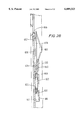
- the high pressure fluid pushes against the seal 309, expanding the expansion chamber 307 pushing the mandrel 327 (downwardly in FIG. 4) which results in the movement of the tubing 302.
- This also decreases the volume of a hydrostatic chamber 325 while increasing the volume of a sub-hydrostatic chamber 326.
- the hydrostatic chamber 325 is defined by an outer surface of the mandrel 327 and an inner surface of sliphousing 314.
- the subhydrostatic chamber 326 is similarly defined. Movement of the mandrel 327 ceases when the seal 309 abuts a stop 315 on the inner surface of the slip housing 314.
- the system 400 has two hydraulic circuits, a power-retract circuit for the two tractor units (including lines 463, 468 and 418) and a control circuit (including lines 464, 465, 467, 472, 470, 471, 407, 460 and 469 and valves 405, 406, 410 and 420).
- FIGS. 6A-6D show a sequence of operation of the system 400.
- FIG. 6A is a duplicate of FIG. 5 and shows an initial position of the system for running it into a wellbore or tubular.
- FIG. 6B the upper tractor unit 413 is in its power stroke and the lower tractor unit 422 is in its retract stroke.
- FIG. 6C the upper tractor unit 413 is in its retract stroke and the power stroke of the lower tractor unit 422 has begun.
- FIG. 6D is like FIG. 6B, but in FIG. 6D the upper unit has just reached the end of a power stroke and is switching to a retract stroke, while the lower unit has just ended its retract stroke and is starting to set its slips.
- a grip-set chamber 439 of the upper tractor unit 413 is equalized to the pressure in the power chamber 437. Therefore, when the pressure inside the power chamber 437 is diverted to (low) sump pressure, a spring 409 forces the fluid out of the grip set chamber 439 back to the sump 432 and allows the grippers to collapse onto the mandrel 418. As the upper tractor unit 413 reverses its direction relative to the mandrel 418, a spring 494 closes the rear pilot control valve 405 shutting off pilot pressure in lines 407 and 472 to the pilot port of the valve 410. The remaining pilot pressure in the line 470 is bled off through a bleed valve 411 back to the tank 432 through the lines 465 and 467.
Abstract
Description
Claims (24)
Priority Applications (1)
| Application Number | Priority Date | Filing Date | Title |
|---|---|---|---|
| US09/318,502 US6089323A (en) | 1996-07-03 | 1999-05-25 | Tractor system |
Applications Claiming Priority (3)
| Application Number | Priority Date | Filing Date | Title |
|---|---|---|---|
| US08/675,176 US5794703A (en) | 1996-07-03 | 1996-07-03 | Wellbore tractor and method of moving an item through a wellbore |
| US09/103,868 US6082461A (en) | 1996-07-03 | 1998-06-24 | Bore tractor system |
| US09/318,502 US6089323A (en) | 1996-07-03 | 1999-05-25 | Tractor system |
Related Parent Applications (1)
| Application Number | Title | Priority Date | Filing Date |
|---|---|---|---|
| US09/103,868 Division US6082461A (en) | 1996-07-03 | 1998-06-24 | Bore tractor system |
Publications (1)
| Publication Number | Publication Date |
|---|---|
| US6089323A true US6089323A (en) | 2000-07-18 |
Family
ID=24709366
Family Applications (3)
| Application Number | Title | Priority Date | Filing Date |
|---|---|---|---|
| US08/675,176 Expired - Lifetime US5794703A (en) | 1996-07-03 | 1996-07-03 | Wellbore tractor and method of moving an item through a wellbore |
| US09/103,868 Expired - Fee Related US6082461A (en) | 1996-07-03 | 1998-06-24 | Bore tractor system |
| US09/318,502 Expired - Lifetime US6089323A (en) | 1996-07-03 | 1999-05-25 | Tractor system |
Family Applications Before (2)
| Application Number | Title | Priority Date | Filing Date |
|---|---|---|---|
| US08/675,176 Expired - Lifetime US5794703A (en) | 1996-07-03 | 1996-07-03 | Wellbore tractor and method of moving an item through a wellbore |
| US09/103,868 Expired - Fee Related US6082461A (en) | 1996-07-03 | 1998-06-24 | Bore tractor system |
Country Status (8)
| Country | Link |
|---|---|
| US (3) | US5794703A (en) |
| EP (1) | EP0951611B2 (en) |
| AU (1) | AU3626797A (en) |
| CA (1) | CA2251358C (en) |
| DE (1) | DE69718819D1 (en) |
| DK (1) | DK0951611T3 (en) |
| NO (1) | NO320076B1 (en) |
| WO (1) | WO1998001651A1 (en) |
Cited By (57)
| Publication number | Priority date | Publication date | Assignee | Title |
|---|---|---|---|---|
| US6230813B1 (en) | 1995-08-22 | 2001-05-15 | Western Well Tool, Inc. | Method of moving a puller-thruster downhole tool |
| US6241031B1 (en) | 1998-12-18 | 2001-06-05 | Western Well Tool, Inc. | Electro-hydraulically controlled tractor |
| US6311778B1 (en) * | 2000-04-18 | 2001-11-06 | Carisella & Cook Ventures | Assembly and subterranean well tool and method of use |
| US20020032126A1 (en) * | 2000-05-02 | 2002-03-14 | Kusmer Daniel P. | Borehole retention device |
| US6460616B1 (en) | 1996-08-15 | 2002-10-08 | Weatherford/Lamb, Inc. | Traction apparatus |
| US6464003B2 (en) * | 2000-05-18 | 2002-10-15 | Western Well Tool, Inc. | Gripper assembly for downhole tractors |
| US20030183383A1 (en) * | 2002-04-02 | 2003-10-02 | Guerrero Julio C. | Mechanism that assists tractoring on uniform and non-uniform surfaces |
| US6629568B2 (en) | 2001-08-03 | 2003-10-07 | Schlumberger Technology Corporation | Bi-directional grip mechanism for a wide range of bore sizes |
| US6679341B2 (en) | 2000-12-01 | 2004-01-20 | Western Well Tool, Inc. | Tractor with improved valve system |
| WO2004016902A1 (en) * | 2002-08-19 | 2004-02-26 | Baker Hughes Incorporated | High expansion anchor system |
| US20040045474A1 (en) * | 2000-11-24 | 2004-03-11 | Simpson Neil Andrew Abercrombie | Bi-directional traction apparatus |
| US6715559B2 (en) * | 2001-12-03 | 2004-04-06 | Western Well Tool, Inc. | Gripper assembly for downhole tractors |
| US6722442B2 (en) | 1996-08-15 | 2004-04-20 | Weatherford/Lamb, Inc. | Subsurface apparatus |
| US20040123113A1 (en) * | 2002-12-18 | 2004-06-24 | Svein Mathiassen | Portable or embedded access and input devices and methods for giving access to access limited devices, apparatuses, appliances, systems or networks |
| US20040168828A1 (en) * | 2003-02-10 | 2004-09-02 | Mock Philip W. | Tractor with improved valve system |
| US20050016302A1 (en) * | 2003-04-30 | 2005-01-27 | Simpson Neil Andrew Abercrombie | Traction apparatus |
| US20050034874A1 (en) * | 2003-07-16 | 2005-02-17 | Guerrero Julio C. | Open hole tractor with tracks |
| US20050145415A1 (en) * | 2004-01-05 | 2005-07-07 | Doering Falk W. | Traction control for downhole tractor |
| US20050199394A1 (en) * | 2001-12-19 | 2005-09-15 | Schlumberger Technology Corporation | Production Profile Determination and Modification System |
| US20050229342A1 (en) * | 2002-03-15 | 2005-10-20 | Simpson Neil Andrew A | Tractors for movement along a pipeline within a fluid flow |
| US20050247488A1 (en) * | 2004-03-17 | 2005-11-10 | Mock Philip W | Roller link toggle gripper and downhole tractor |
| US20050257933A1 (en) * | 2004-05-20 | 2005-11-24 | Bernd-Georg Pietras | Casing running head |
| US20070107941A1 (en) * | 2005-10-27 | 2007-05-17 | Fillipov Andrei G | Extended reach drilling apparatus & method |
| US20070209806A1 (en) * | 2006-03-13 | 2007-09-13 | Mock Phillip W | Expandable ramp gripper |
| US20080053663A1 (en) * | 2006-08-24 | 2008-03-06 | Western Well Tool, Inc. | Downhole tool with turbine-powered motor |
| US20080066963A1 (en) * | 2006-09-15 | 2008-03-20 | Todor Sheiretov | Hydraulically driven tractor |
| US20080073077A1 (en) * | 2004-05-28 | 2008-03-27 | Gokturk Tunc | Coiled Tubing Tractor Assembly |
| US20080196901A1 (en) * | 2007-02-19 | 2008-08-21 | Franz Aguirre | Self-Aligning Open-Hole Tractor |
| US20080217024A1 (en) * | 2006-08-24 | 2008-09-11 | Western Well Tool, Inc. | Downhole tool with closed loop power systems |
| US20090218105A1 (en) * | 2007-01-02 | 2009-09-03 | Hill Stephen D | Hydraulically Driven Tandem Tractor Assembly |
| US20090229820A1 (en) * | 2006-02-09 | 2009-09-17 | Gohar Saeed | Downhole Sensor Interface |
| US20090236101A1 (en) * | 2006-02-09 | 2009-09-24 | Nelson Keith R | Force Monitoring Tractor |
| US7650944B1 (en) | 2003-07-11 | 2010-01-26 | Weatherford/Lamb, Inc. | Vessel for well intervention |
| US20100065280A1 (en) * | 2008-09-18 | 2010-03-18 | Baker Hughes Inc. | Gas restrictor for horizontally oriented pump |
| US7685946B1 (en) * | 2007-06-25 | 2010-03-30 | Elstone Iii John M | Tubular transporter |
| US7712523B2 (en) | 2000-04-17 | 2010-05-11 | Weatherford/Lamb, Inc. | Top drive casing system |
| US7730965B2 (en) | 2002-12-13 | 2010-06-08 | Weatherford/Lamb, Inc. | Retractable joint and cementing shoe for use in completing a wellbore |
| US7748476B2 (en) | 2006-11-14 | 2010-07-06 | Wwt International, Inc. | Variable linkage assisted gripper |
| US20100307832A1 (en) * | 2000-12-01 | 2010-12-09 | Western Well Tool, Inc. | Tractor with improved valve system |
| US7857052B2 (en) | 2006-05-12 | 2010-12-28 | Weatherford/Lamb, Inc. | Stage cementing methods used in casing while drilling |
| US20110073300A1 (en) * | 2009-09-29 | 2011-03-31 | Mock Philip W | Methods and apparatuses for inhibiting rotational misalignment of assemblies in expandable well tools |
| US7938201B2 (en) | 2002-12-13 | 2011-05-10 | Weatherford/Lamb, Inc. | Deep water drilling with casing |
| US20110127046A1 (en) * | 2009-12-01 | 2011-06-02 | Franz Aguirre | Grip Enhanced Tractoring |
| USRE42877E1 (en) | 2003-02-07 | 2011-11-01 | Weatherford/Lamb, Inc. | Methods and apparatus for wellbore construction and completion |
| US8172009B2 (en) | 2010-07-14 | 2012-05-08 | Hall David R | Expandable tool with at least one blade that locks in place through a wedging effect |
| US20120193147A1 (en) * | 2011-01-28 | 2012-08-02 | Hall David R | Fluid Path between the Outer Surface of a Tool and an Expandable Blade |
| US8276689B2 (en) | 2006-05-22 | 2012-10-02 | Weatherford/Lamb, Inc. | Methods and apparatus for drilling with casing |
| US8281880B2 (en) | 2010-07-14 | 2012-10-09 | Hall David R | Expandable tool for an earth boring system |
| US8353354B2 (en) | 2010-07-14 | 2013-01-15 | Hall David R | Crawler system for an earth boring system |
| US20130025215A1 (en) * | 2007-12-21 | 2013-01-31 | Schlumberger Technology Corporation | System and methods for actuating reversibly expandable structures |
| US20130134971A1 (en) * | 2011-11-28 | 2013-05-30 | Baker Hughes Incorporated | Media displacement device and method of improving transfer of electromagnetic energy between a tool and an earth formation |
| US8839883B2 (en) * | 2012-02-13 | 2014-09-23 | Halliburton Energy Services, Inc. | Piston tractor system for use in subterranean wells |
| US9447648B2 (en) | 2011-10-28 | 2016-09-20 | Wwt North America Holdings, Inc | High expansion or dual link gripper |
| US9488020B2 (en) | 2014-01-27 | 2016-11-08 | Wwt North America Holdings, Inc. | Eccentric linkage gripper |
| US9708867B2 (en) | 2004-05-28 | 2017-07-18 | Schlumberger Technology Corporation | System and methods using fiber optics in coiled tubing |
| CN107605418A (en) * | 2017-10-27 | 2018-01-19 | 中国石油集团渤海钻探工程有限公司 | A kind of coiled tubing waterpower draws crawl device |
| US10927625B2 (en) | 2018-05-10 | 2021-02-23 | Colorado School Of Mines | Downhole tractor for use in a wellbore |
Families Citing this family (93)
| Publication number | Priority date | Publication date | Assignee | Title |
|---|---|---|---|---|
| GB2342674B (en) * | 1995-08-22 | 2000-05-31 | Western Well Tool Inc | Puller-thruster downhole tool |
| US6003606A (en) * | 1995-08-22 | 1999-12-21 | Western Well Tool, Inc. | Puller-thruster downhole tool |
| GB2340526B (en) * | 1995-08-22 | 2000-05-31 | Western Well Tool Inc | Puller-thruster downhole tool |
| WO1997008418A1 (en) * | 1995-08-22 | 1997-03-06 | Western Well Tool, Inc. | Puller-thruster downhole tool |
| GB9614761D0 (en) | 1996-07-13 | 1996-09-04 | Schlumberger Ltd | Downhole tool and method |
| CA2238334C (en) | 1996-09-23 | 2008-04-22 | Intelligent Inspection Corporation Commonwealth Of Massachusetts | Autonomous downhole oilfield tool |
| US6112809A (en) * | 1996-12-02 | 2000-09-05 | Intelligent Inspection Corporation | Downhole tools with a mobility device |
| US6142245A (en) * | 1997-08-19 | 2000-11-07 | Shell Oil Company | Extended reach drilling system |
| US6102138A (en) * | 1997-08-20 | 2000-08-15 | Baker Hughes Incorporated | Pressure-modulation valve assembly |
| US5954131A (en) * | 1997-09-05 | 1999-09-21 | Schlumberger Technology Corporation | Method and apparatus for conveying a logging tool through an earth formation |
| US6179055B1 (en) | 1997-09-05 | 2001-01-30 | Schlumberger Technology Corporation | Conveying a tool along a non-vertical well |
| US6962216B2 (en) | 2002-05-31 | 2005-11-08 | Cdx Gas, Llc | Wedge activated underreamer |
| GB2378468B (en) * | 1998-12-18 | 2003-04-02 | Western Well Tool Inc | Electrically sequenced tractor |
| US6470974B1 (en) * | 1999-04-14 | 2002-10-29 | Western Well Tool, Inc. | Three-dimensional steering tool for controlled downhole extended-reach directional drilling |
| US6467557B1 (en) | 1998-12-18 | 2002-10-22 | Western Well Tool, Inc. | Long reach rotary drilling assembly |
| US6347674B1 (en) * | 1998-12-18 | 2002-02-19 | Western Well Tool, Inc. | Electrically sequenced tractor |
| US6273189B1 (en) | 1999-02-05 | 2001-08-14 | Halliburton Energy Services, Inc. | Downhole tractor |
| NO320782B1 (en) * | 1999-03-22 | 2006-01-30 | Aatechnology As | Progress mechanism for long voids and rudders |
| WO2001011179A1 (en) * | 1999-08-04 | 2001-02-15 | Chunfang Wang | A drilling device |
| US6257332B1 (en) | 1999-09-14 | 2001-07-10 | Halliburton Energy Services, Inc. | Well management system |
| NO311100B1 (en) * | 1999-10-26 | 2001-10-08 | Bakke Technology As | Apparatus for use in feeding a rotary downhole tool and using the apparatus |
| US6367366B1 (en) | 1999-12-02 | 2002-04-09 | Western Well Tool, Inc. | Sensor assembly |
| US6431291B1 (en) | 2001-06-14 | 2002-08-13 | Western Well Tool, Inc. | Packerfoot with bladder assembly having reduced likelihood of bladder delamination |
| US6789456B2 (en) * | 2001-08-29 | 2004-09-14 | Battelle Memorial Institute | Braking system |
| US6578464B2 (en) * | 2001-08-29 | 2003-06-17 | Battelle Memorial Institute | Recoil mitigation device |
| US6745663B2 (en) | 2001-08-29 | 2004-06-08 | Battelle Memorial Institute | Apparatus for mitigating recoil and method thereof |
| US6615931B2 (en) * | 2002-01-07 | 2003-09-09 | Boart Longyear Co. | Continuous feed drilling system |
| GB2420579B (en) * | 2002-02-11 | 2006-09-06 | Baker Hughes Inc | Method of repair of collapsed or damaged tubulars downhole |
| US6722452B1 (en) | 2002-02-19 | 2004-04-20 | Cdx Gas, Llc | Pantograph underreamer |
| US7156182B2 (en) | 2002-03-07 | 2007-01-02 | Baker Hughes Incorporated | Method and apparatus for one trip tubular expansion |
| US6976547B2 (en) | 2002-07-16 | 2005-12-20 | Cdx Gas, Llc | Actuator underreamer |
| US7007758B2 (en) * | 2002-07-17 | 2006-03-07 | Cdx Gas, Llc | Cavity positioning tool and method |
| US6851479B1 (en) * | 2002-07-17 | 2005-02-08 | Cdx Gas, Llc | Cavity positioning tool and method |
| NO20025798D0 (en) * | 2002-12-03 | 2002-12-03 | Bakke Oil Tools As | Device and method of downhole controlled tool |
| GB2414499B (en) * | 2003-02-10 | 2006-06-28 | Western Well Tool Inc | Tractor with improved valve system |
| US20060054354A1 (en) * | 2003-02-11 | 2006-03-16 | Jacques Orban | Downhole tool |
| WO2004079157A1 (en) * | 2003-02-28 | 2004-09-16 | Baker Hughes Incorporated | Compliant swage |
| US6978844B2 (en) * | 2003-07-03 | 2005-12-27 | Lafleur Petroleum Services, Inc. | Filling and circulating apparatus for subsurface exploration |
| NO319232B1 (en) * | 2003-10-09 | 2005-07-04 | Hpi As | Feed pump for a sand removal device in a underground well |
| DE602004014498D1 (en) * | 2004-09-20 | 2008-07-31 | Schlumberger Technology Bv | Pulling device for drilling |
| US7182157B2 (en) * | 2004-12-21 | 2007-02-27 | Cdx Gas, Llc | Enlarging well bores having tubing therein |
| GB0515070D0 (en) * | 2005-07-22 | 2005-08-31 | Moyes Peter B | Downhole tool |
| EP1780372B1 (en) | 2005-08-08 | 2009-12-16 | Services Pétroliers Schlumberger | Drilling system |
| US20080047715A1 (en) * | 2006-08-24 | 2008-02-28 | Moore N Bruce | Wellbore tractor with fluid conduit sheath |
| WO2008157428A2 (en) * | 2007-06-14 | 2008-12-24 | Western Well Tool, Inc. | Electrically powered tractor |
| GB2454697B (en) | 2007-11-15 | 2011-11-30 | Schlumberger Holdings | Anchoring systems for drilling tools |
| NO333300B1 (en) * | 2008-06-05 | 2013-04-29 | Norwegian Hard Rock Drilling As | Device by rock drill |
| US9242309B2 (en) | 2012-03-01 | 2016-01-26 | Foro Energy Inc. | Total internal reflection laser tools and methods |
| US9080425B2 (en) | 2008-10-17 | 2015-07-14 | Foro Energy, Inc. | High power laser photo-conversion assemblies, apparatuses and methods of use |
| US9347271B2 (en) | 2008-10-17 | 2016-05-24 | Foro Energy, Inc. | Optical fiber cable for transmission of high power laser energy over great distances |
| US9027668B2 (en) | 2008-08-20 | 2015-05-12 | Foro Energy, Inc. | Control system for high power laser drilling workover and completion unit |
| US8820434B2 (en) | 2008-08-20 | 2014-09-02 | Foro Energy, Inc. | Apparatus for advancing a wellbore using high power laser energy |
| US9267330B2 (en) | 2008-08-20 | 2016-02-23 | Foro Energy, Inc. | Long distance high power optical laser fiber break detection and continuity monitoring systems and methods |
| US9719302B2 (en) | 2008-08-20 | 2017-08-01 | Foro Energy, Inc. | High power laser perforating and laser fracturing tools and methods of use |
| US9074422B2 (en) | 2011-02-24 | 2015-07-07 | Foro Energy, Inc. | Electric motor for laser-mechanical drilling |
| US8627901B1 (en) | 2009-10-01 | 2014-01-14 | Foro Energy, Inc. | Laser bottom hole assembly |
| US9244235B2 (en) | 2008-10-17 | 2016-01-26 | Foro Energy, Inc. | Systems and assemblies for transferring high power laser energy through a rotating junction |
| US9360631B2 (en) | 2008-08-20 | 2016-06-07 | Foro Energy, Inc. | Optics assembly for high power laser tools |
| US10301912B2 (en) * | 2008-08-20 | 2019-05-28 | Foro Energy, Inc. | High power laser flow assurance systems, tools and methods |
| US9664012B2 (en) | 2008-08-20 | 2017-05-30 | Foro Energy, Inc. | High power laser decomissioning of multistring and damaged wells |
| US9138786B2 (en) | 2008-10-17 | 2015-09-22 | Foro Energy, Inc. | High power laser pipeline tool and methods of use |
| US9669492B2 (en) | 2008-08-20 | 2017-06-06 | Foro Energy, Inc. | High power laser offshore decommissioning tool, system and methods of use |
| US8571368B2 (en) | 2010-07-21 | 2013-10-29 | Foro Energy, Inc. | Optical fiber configurations for transmission of laser energy over great distances |
| US9089928B2 (en) | 2008-08-20 | 2015-07-28 | Foro Energy, Inc. | Laser systems and methods for the removal of structures |
| EP2290190A1 (en) * | 2009-08-31 | 2011-03-02 | Services Petroliers Schlumberger | Method and apparatus for controlled bidirectional movement of an oilfield tool in a wellbore environment |
| WO2012024285A1 (en) | 2010-08-17 | 2012-02-23 | Foro Energy Inc. | Systems and conveyance structures for high power long distance laster transmission |
| BR112013021478A2 (en) | 2011-02-24 | 2016-10-11 | Foro Energy Inc | High power laser-mechanical drilling method |
| WO2012167102A1 (en) | 2011-06-03 | 2012-12-06 | Foro Energy Inc. | Rugged passively cooled high power laser fiber optic connectors and methods of use |
| US8973651B2 (en) | 2011-06-16 | 2015-03-10 | Baker Hughes Incorporated | Modular anchoring sub for use with a cutting tool |
| US8844636B2 (en) | 2012-01-18 | 2014-09-30 | Baker Hughes Incorporated | Hydraulic assist deployment system for artificial lift systems |
| EP2847416A4 (en) | 2012-06-14 | 2016-09-21 | Halliburton Energy Services Inc | Well tractor |
| US10865614B2 (en) | 2012-07-24 | 2020-12-15 | Robertson Intellectual Properties, LLC | Systems and methods for setting an extreme-range anchor within a wellbore |
| US10294744B2 (en) * | 2012-07-24 | 2019-05-21 | Robertson Intellectual Properties, LLC | Systems and methods for setting an extreme-range anchor within a wellbore |
| CN102808589B (en) * | 2012-08-16 | 2015-07-08 | 中国石油大学(北京) | Motor-driven underground tractor for coiled tubing |
| US10774602B2 (en) | 2013-12-20 | 2020-09-15 | Halliburton Energy Services, Inc. | High radial expansion anchoring tool |
| CN104060960A (en) * | 2014-06-25 | 2014-09-24 | 中国石油大学(北京) | Self-straightening type underground drawing device |
| CN105239946B (en) * | 2015-07-23 | 2017-12-08 | 重庆科技学院 | The experimental provision of coiled tubing tractor |
| GB2533019B (en) * | 2015-08-19 | 2016-10-12 | Global Tech And Innovation Ltd | A downhole tractor including a drive mechanism |
| GB2530651B (en) * | 2015-08-19 | 2016-10-19 | Global Tech And Innovation Ltd | A downhole tractor |
| GB2533018B (en) * | 2015-08-19 | 2016-10-19 | Global Tech And Innovation Ltd | An expander assembly |
| US10221687B2 (en) | 2015-11-26 | 2019-03-05 | Merger Mines Corporation | Method of mining using a laser |
| CN105332667B (en) * | 2015-11-26 | 2018-07-24 | 长江大学 | A kind of coiled tubing tractor |
| CN105649561B (en) * | 2016-03-10 | 2017-10-17 | 长江大学 | A kind of coiled tubing tractor |
| WO2018102353A1 (en) * | 2016-12-01 | 2018-06-07 | Shell Oil Company | Light weight subsea systems |
| CN106677732A (en) * | 2016-12-30 | 2017-05-17 | 中国人民解放军国防科学技术大学 | All-hydraulic petroleum downhole traction device |
| CN107366523B (en) * | 2017-08-17 | 2019-03-22 | 西南石油大学 | A kind of coiled tubing traction robot |
| CN108931345B (en) * | 2018-09-10 | 2020-08-28 | 陈朝晖 | Suppress leak hunting device |
| US11442193B2 (en) | 2019-05-17 | 2022-09-13 | Halliburton Energy Services, Inc. | Passive arm for bi-directional well logging instrument |
| AU2021267166A1 (en) * | 2020-05-07 | 2022-12-08 | Baker Hughes Oilfield Operations Llc | Chemical injection system for completed wellbores |
| CN112065312B (en) * | 2020-09-30 | 2023-11-10 | 中国石油天然气集团有限公司 | Hydraulic telescopic coiled tubing tractor for dense gas operation and use method |
| US11624250B1 (en) * | 2021-06-04 | 2023-04-11 | Coiled Tubing Specialties, Llc | Apparatus and method for running and retrieving tubing using an electro-mechanical linear actuator driven downhole tractor |
| CN114482888B (en) * | 2021-12-22 | 2024-02-27 | 中国石油天然气集团有限公司 | Underground electrohydraulic control active pressurizer |
| GB2617211A (en) * | 2022-06-27 | 2023-10-04 | Hypertunnel Ip Ltd | Apparatus and method of deploying a pipe within a borehole |
Citations (54)
| Publication number | Priority date | Publication date | Assignee | Title |
|---|---|---|---|---|
| US3307631A (en) * | 1963-04-30 | 1967-03-07 | Kobe Inc | Apparatus for running equipment into and out of offshore well completions |
| US3313346A (en) * | 1964-12-24 | 1967-04-11 | Chevron Res | Continuous tubing well working system |
| US3346045A (en) * | 1965-05-20 | 1967-10-10 | Exxon Production Research Co | Operation in a submarine well |
| US3559905A (en) * | 1968-01-09 | 1971-02-02 | Corod Mfg Ltd | roeder; Werner H. |
| US3724567A (en) * | 1970-11-30 | 1973-04-03 | E Smitherman | Apparatus for handling column of drill pipe or tubing during drilling or workover operations |
| US3841407A (en) * | 1973-01-02 | 1974-10-15 | J Bozeman | Coil tubing unit |
| US4050384A (en) * | 1974-09-09 | 1977-09-27 | Babcock & Wilcox Limited | Tube inspection and servicing apparatus |
| US4071086A (en) * | 1976-06-22 | 1978-01-31 | Suntech, Inc. | Apparatus for pulling tools into a wellbore |
| US4095655A (en) * | 1975-10-14 | 1978-06-20 | Still William L | Earth penetration |
| US4112850A (en) * | 1976-02-24 | 1978-09-12 | Sigel Gfeller Alwin | Conveyor apparatus for the interior of pipelines |
| US4141414A (en) * | 1976-11-05 | 1979-02-27 | Johansson Sven H | Device for supporting, raising and lowering duct in deep bore hole |
| US4177734A (en) * | 1977-10-03 | 1979-12-11 | Midcon Pipeline Equipment Co. | Drive unit for internal pipe line equipment |
| US4192380A (en) * | 1978-10-02 | 1980-03-11 | Dresser Industries, Inc. | Method and apparatus for logging inclined earth boreholes |
| US4223737A (en) * | 1979-03-26 | 1980-09-23 | Reilly Dale O | Method for well operations |
| US4244296A (en) * | 1977-02-24 | 1981-01-13 | Commissariat A L'energie Atomique | Self-propelled vehicle |
| US4369713A (en) * | 1980-10-20 | 1983-01-25 | Transcanada Pipelines Ltd. | Pipeline crawler |
| US4372161A (en) * | 1981-02-25 | 1983-02-08 | Buda Eric G De | Pneumatically operated pipe crawler |
| US4403551A (en) * | 1979-08-21 | 1983-09-13 | Post Office | Pneumatically propelled duct motor |
| US4463814A (en) * | 1982-11-26 | 1984-08-07 | Advanced Drilling Corporation | Down-hole drilling apparatus |
| US4522129A (en) * | 1980-05-28 | 1985-06-11 | Nitro Nobel Ab | Device for charging drillholes |
| EP0149528A1 (en) * | 1984-01-19 | 1985-07-24 | British Gas Corporation | Device for replacing mains |
| US4537136A (en) * | 1982-02-02 | 1985-08-27 | Subscan Systems Ltd. | Pipeline vehicle |
| US4558751A (en) * | 1984-08-02 | 1985-12-17 | Exxon Production Research Co. | Apparatus for transporting equipment through a conduit |
| US4654102A (en) * | 1982-08-03 | 1987-03-31 | Burroughs Corporation | Method for correcting printed circuit boards |
| US4686653A (en) * | 1983-12-09 | 1987-08-11 | Societe Nationale Elf Aquitaine (Production) | Method and device for making geophysical measurements within a wellbore |
| US4770105A (en) * | 1985-08-07 | 1988-09-13 | Hitachi, Ltd. | Piping travelling apparatus |
| US4838170A (en) * | 1988-10-17 | 1989-06-13 | Mcdermott International, Inc. | Drive wheel unit |
| US4862808A (en) * | 1988-08-29 | 1989-09-05 | Gas Research Institute | Robotic pipe crawling device |
| US4919223A (en) * | 1988-01-15 | 1990-04-24 | Shawn E. Egger | Apparatus for remotely controlled movement through tubular conduit |
| US4940095A (en) * | 1989-01-27 | 1990-07-10 | Dowell Schlumberger Incorporated | Deployment/retrieval method and apparatus for well tools used with coiled tubing |
| US4981080A (en) * | 1989-01-23 | 1991-01-01 | Elstone Iii John M | Pump transport device |
| US5018451A (en) * | 1990-01-05 | 1991-05-28 | The United States Of America As Represented By The United States Department Of Energy | Extendable pipe crawler |
| US5060737A (en) * | 1986-07-01 | 1991-10-29 | Framo Developments (Uk) Limited | Drilling system |
| US5080020A (en) * | 1989-07-14 | 1992-01-14 | Nihon Kohden Corporation | Traveling device having elastic contractible body moving along elongated member |
| US5121694A (en) * | 1991-04-02 | 1992-06-16 | Zollinger William T | Pipe crawler with extendable legs |
| US5142990A (en) * | 1990-06-11 | 1992-09-01 | Ecole Superieure Des Sciences Et Technologies De L'ingenieur De Nancy (Esstin) | Self-propelled and articulated vehicle with telescopic jacks to carry pipework inspection equipment |
| US5142989A (en) * | 1990-09-28 | 1992-09-01 | Kabushiki Kaisha Toshiba | Propelling mechanism and traveling device propelled thereby |
| US5172639A (en) * | 1991-03-26 | 1992-12-22 | Gas Research Institute | Cornering pipe traveler |
| US5184676A (en) * | 1990-02-26 | 1993-02-09 | Graham Gordon A | Self-propelled apparatus |
| US5220869A (en) * | 1991-08-07 | 1993-06-22 | Osaka Gas Company, Ltd. | Vehicle adapted to freely travel three-dimensionally and up vertical walls by magnetic force and wheel for the vehicle |
| EP0565287A1 (en) * | 1992-03-31 | 1993-10-13 | Philip Frederick Head | Undulated conduit anchored in coiled tubing |
| US5272986A (en) * | 1991-05-13 | 1993-12-28 | British Gas Plc | Towing swivel for pipe inspection or other vehicle |
| US5293823A (en) * | 1992-09-23 | 1994-03-15 | Box W Donald | Robotic vehicle |
| US5309844A (en) * | 1993-05-24 | 1994-05-10 | The United States Of America As Represented By The United States Department Of Energy | Flexible pipe crawling device having articulated two axis coupling |
| US5375530A (en) * | 1993-09-20 | 1994-12-27 | The United States Of America As Represented By The Department Of Energy | Pipe crawler with stabilizing midsection |
| US5388528A (en) * | 1991-08-06 | 1995-02-14 | Osaka Gas Company, Limited | Vehicle for use in pipes |
| US5392715A (en) * | 1993-10-12 | 1995-02-28 | Osaka Gas Company, Ltd. | In-pipe running robot and method of running the robot |
| GB2282170A (en) * | 1992-05-27 | 1995-03-29 | Astec Dev Ltd | Downhole tools |
| US5435395A (en) * | 1994-03-22 | 1995-07-25 | Halliburton Company | Method for running downhole tools and devices with coiled tubing |
| US5515925A (en) * | 1994-09-19 | 1996-05-14 | Boychuk; Randy J. | Apparatus and method for installing coiled tubing in a well |
| US5788002A (en) * | 1993-02-01 | 1998-08-04 | Siemens Aktiengesellschaft | Transport device being movable automatically inside a pipe |
| US5833004A (en) * | 1996-01-22 | 1998-11-10 | Baker Hughes Incorporated | Running liners with coiled tubing |
| US5845711A (en) * | 1995-06-02 | 1998-12-08 | Halliburton Company | Coiled tubing apparatus |
| EP0900914A2 (en) * | 1997-09-05 | 1999-03-10 | Schlumberger Limited (a Netherland Antilles corp.) | Method and apparatus for conveying a logging tool through an earth formation |
Family Cites Families (48)
| Publication number | Priority date | Publication date | Assignee | Title |
|---|---|---|---|---|
| US3180437A (en) † | 1961-05-22 | 1965-04-27 | Jersey Prod Res Co | Force applicator for drill bit |
| US3471921A (en) * | 1965-12-23 | 1969-10-14 | Shell Oil Co | Method of connecting a steel blank to a tungsten bit body |
| FR2048156A5 (en) † | 1969-06-03 | 1971-03-19 | Schlumberger Prospection | |
| FR2085481A1 (en) † | 1970-04-24 | 1971-12-24 | Schlumberger Prospection | Anchoring device - for use in locating a detector for a jammed drilling string |
| US3757879A (en) * | 1972-08-24 | 1973-09-11 | Christensen Diamond Prod Co | Drill bits and methods of producing drill bits |
| US3757878A (en) * | 1972-08-24 | 1973-09-11 | Christensen Diamond Prod Co | Drill bits and method of producing drill bits |
| CA1050726A (en) * | 1973-04-14 | 1979-03-20 | Ciba-Geigy Ag | Method of making a foundry mould or core with an anaerobically cured adhesive |
| US4064926A (en) * | 1975-06-16 | 1977-12-27 | Acme-Cleveland Corporation | Sand molding apparatus with means for recirculating catalyst |
| GB1572543A (en) * | 1978-05-26 | 1980-07-30 | Smit & Sons Diamond Tools | Drilling tools |
| US4414028A (en) * | 1979-04-11 | 1983-11-08 | Inoue-Japax Research Incorporated | Method of and apparatus for sintering a mass of particles with a powdery mold |
| US4484644A (en) * | 1980-09-02 | 1984-11-27 | Ingersoll-Rand Company | Sintered and forged article, and method of forming same |
| US4398952A (en) * | 1980-09-10 | 1983-08-16 | Reed Rock Bit Company | Methods of manufacturing gradient composite metallic structures |
| US4423646A (en) * | 1981-03-30 | 1984-01-03 | N.C. Securities Holding, Inc. | Process for producing a rotary drilling bit |
| ZW12583A1 (en) * | 1982-06-08 | 1983-08-24 | Boart Int Ltd | Drilling bit |
| EP0145421B1 (en) * | 1983-12-03 | 1989-07-26 | Reed Tool Company Limited | Improvements in or relating to the manufacture of rotary drill bits |
| DE3347501C3 (en) * | 1983-12-29 | 1993-12-02 | Uwe Christian Seefluth | Drilling tool with hard metal insert body, manufacturing process for hard metal insert body |
| US5017753A (en) * | 1986-10-17 | 1991-05-21 | Board Of Regents, The University Of Texas System | Method and apparatus for producing parts by selective sintering |
| US4863538A (en) * | 1986-10-17 | 1989-09-05 | Board Of Regents, The University Of Texas System | Method and apparatus for producing parts by selective sintering |
| EP0538244B1 (en) * | 1986-10-17 | 1996-05-22 | Board Of Regents, The University Of Texas System | Method and apparatus for producing parts by selective sintering |
| US5155324A (en) * | 1986-10-17 | 1992-10-13 | Deckard Carl R | Method for selective laser sintering with layerwise cross-scanning |
| US4702304A (en) * | 1986-11-03 | 1987-10-27 | General Motors Corporation | Foundry mold for cast-to-size zinc-base alloy |
| US5090491A (en) * | 1987-10-13 | 1992-02-25 | Eastman Christensen Company | Earth boring drill bit with matrix displacing material |
| US4884477A (en) * | 1988-03-31 | 1989-12-05 | Eastman Christensen Company | Rotary drill bit with abrasion and erosion resistant facing |
| GB2230981B (en) * | 1988-07-08 | 1993-01-27 | Honda Motor Co Ltd | Method of producing pattern for molding castings |
| US4919013A (en) * | 1988-09-14 | 1990-04-24 | Eastman Christensen Company | Preformed elements for a rotary drill bit |
| US5182170A (en) * | 1989-09-05 | 1993-01-26 | Board Of Regents, The University Of Texas System | Method of producing parts by selective beam interaction of powder with gas phase reactant |
| US5156697A (en) * | 1989-09-05 | 1992-10-20 | Board Of Regents, The University Of Texas System | Selective laser sintering of parts by compound formation of precursor powders |
| GB8921017D0 (en) * | 1989-09-16 | 1989-11-01 | Astec Dev Ltd | Drill bit or corehead manufacturing process |
| US5000273A (en) * | 1990-01-05 | 1991-03-19 | Norton Company | Low melting point copper-manganese-zinc alloy for infiltration binder in matrix body rock drill bits |
| US5155321A (en) * | 1990-11-09 | 1992-10-13 | Dtm Corporation | Radiant heating apparatus for providing uniform surface temperature useful in selective laser sintering |
| US5385780A (en) * | 1990-12-05 | 1995-01-31 | The B. F. Goodrich Company | Sinterable mass of polymer powder having resistance to caking and method of preparing the mass |
| SE500049C2 (en) * | 1991-02-05 | 1994-03-28 | Sandvik Ab | Cemented carbide body with increased toughness for mineral felling and ways of making it |
| DE69221983D1 (en) * | 1991-10-09 | 1997-10-09 | Smith International | Diamond cutting insert with a convex cutting surface |
| US5252264A (en) * | 1991-11-08 | 1993-10-12 | Dtm Corporation | Apparatus and method for producing parts with multi-directional powder delivery |
| DK0661926T3 (en) | 1992-03-03 | 1998-10-12 | Wrigley W M Jun Co | Wax-free chewing gum comprising special oligosaccharide binders |
| US5342919A (en) * | 1992-11-23 | 1994-08-30 | Dtm Corporation | Sinterable semi-crystalline powder and near-fully dense article formed therewith |
| US5304329A (en) * | 1992-11-23 | 1994-04-19 | The B. F. Goodrich Company | Method of recovering recyclable unsintered powder from the part bed of a selective laser-sintering machine |
| US5352405A (en) * | 1992-12-18 | 1994-10-04 | Dtm Corporation | Thermal control of selective laser sintering via control of the laser scan |
| GB9226815D0 (en) * | 1992-12-23 | 1993-02-17 | Borden Uk Ltd | Improvements in or relating to water dispersible moulds |
| US5373907A (en) * | 1993-01-26 | 1994-12-20 | Dresser Industries, Inc. | Method and apparatus for manufacturing and inspecting the quality of a matrix body drill bit |
| US5511603A (en) * | 1993-03-26 | 1996-04-30 | Chesapeake Composites Corporation | Machinable metal-matrix composite and liquid metal infiltration process for making same |
| GB9308363D0 (en) * | 1993-04-22 | 1993-06-09 | Foseco Int | Refractory compositions for use in the casting of metals |
| DK169236B1 (en) * | 1993-07-20 | 1994-09-19 | Dansk Ind Syndikat | Process for making molds or parts thereof by compressing particulate matter and apparatus for carrying out the process |
| US5441121A (en) * | 1993-12-22 | 1995-08-15 | Baker Hughes, Inc. | Earth boring drill bit with shell supporting an external drilling surface |
| US5433280A (en) * | 1994-03-16 | 1995-07-18 | Baker Hughes Incorporated | Fabrication method for rotary bits and bit components and bits and components produced thereby |
| GB9500286D0 (en) * | 1995-01-07 | 1995-03-01 | Camco Drilling Group Ltd | Improvements in or relating to the manufacture of rotary drill bits |
| US5663883A (en) * | 1995-08-21 | 1997-09-02 | University Of Utah Research Foundation | Rapid prototyping method |
| WO1997008418A1 (en) * | 1995-08-22 | 1997-03-06 | Western Well Tool, Inc. | Puller-thruster downhole tool |
-
1996
- 1996-07-03 US US08/675,176 patent/US5794703A/en not_active Expired - Lifetime
-
1997
- 1997-07-03 DK DK97932899T patent/DK0951611T3/en active
- 1997-07-03 CA CA002251358A patent/CA2251358C/en not_active Expired - Lifetime
- 1997-07-03 DE DE69718819T patent/DE69718819D1/en not_active Expired - Lifetime
- 1997-07-03 EP EP97932899A patent/EP0951611B2/en not_active Expired - Lifetime
- 1997-07-03 WO PCT/GB1997/001868 patent/WO1998001651A1/en active IP Right Grant
- 1997-07-31 AU AU36267/97A patent/AU3626797A/en not_active Abandoned
-
1998
- 1998-06-24 US US09/103,868 patent/US6082461A/en not_active Expired - Fee Related
- 1998-10-01 NO NO19984584A patent/NO320076B1/en active IP Right Review Request
-
1999
- 1999-05-25 US US09/318,502 patent/US6089323A/en not_active Expired - Lifetime
Patent Citations (54)
| Publication number | Priority date | Publication date | Assignee | Title |
|---|---|---|---|---|
| US3307631A (en) * | 1963-04-30 | 1967-03-07 | Kobe Inc | Apparatus for running equipment into and out of offshore well completions |
| US3313346A (en) * | 1964-12-24 | 1967-04-11 | Chevron Res | Continuous tubing well working system |
| US3346045A (en) * | 1965-05-20 | 1967-10-10 | Exxon Production Research Co | Operation in a submarine well |
| US3559905A (en) * | 1968-01-09 | 1971-02-02 | Corod Mfg Ltd | roeder; Werner H. |
| US3724567A (en) * | 1970-11-30 | 1973-04-03 | E Smitherman | Apparatus for handling column of drill pipe or tubing during drilling or workover operations |
| US3841407A (en) * | 1973-01-02 | 1974-10-15 | J Bozeman | Coil tubing unit |
| US4050384A (en) * | 1974-09-09 | 1977-09-27 | Babcock & Wilcox Limited | Tube inspection and servicing apparatus |
| US4095655A (en) * | 1975-10-14 | 1978-06-20 | Still William L | Earth penetration |
| US4112850A (en) * | 1976-02-24 | 1978-09-12 | Sigel Gfeller Alwin | Conveyor apparatus for the interior of pipelines |
| US4071086A (en) * | 1976-06-22 | 1978-01-31 | Suntech, Inc. | Apparatus for pulling tools into a wellbore |
| US4141414A (en) * | 1976-11-05 | 1979-02-27 | Johansson Sven H | Device for supporting, raising and lowering duct in deep bore hole |
| US4244296A (en) * | 1977-02-24 | 1981-01-13 | Commissariat A L'energie Atomique | Self-propelled vehicle |
| US4177734A (en) * | 1977-10-03 | 1979-12-11 | Midcon Pipeline Equipment Co. | Drive unit for internal pipe line equipment |
| US4192380A (en) * | 1978-10-02 | 1980-03-11 | Dresser Industries, Inc. | Method and apparatus for logging inclined earth boreholes |
| US4223737A (en) * | 1979-03-26 | 1980-09-23 | Reilly Dale O | Method for well operations |
| US4403551A (en) * | 1979-08-21 | 1983-09-13 | Post Office | Pneumatically propelled duct motor |
| US4522129A (en) * | 1980-05-28 | 1985-06-11 | Nitro Nobel Ab | Device for charging drillholes |
| US4369713A (en) * | 1980-10-20 | 1983-01-25 | Transcanada Pipelines Ltd. | Pipeline crawler |
| US4372161A (en) * | 1981-02-25 | 1983-02-08 | Buda Eric G De | Pneumatically operated pipe crawler |
| US4537136A (en) * | 1982-02-02 | 1985-08-27 | Subscan Systems Ltd. | Pipeline vehicle |
| US4654102A (en) * | 1982-08-03 | 1987-03-31 | Burroughs Corporation | Method for correcting printed circuit boards |
| US4463814A (en) * | 1982-11-26 | 1984-08-07 | Advanced Drilling Corporation | Down-hole drilling apparatus |
| US4686653A (en) * | 1983-12-09 | 1987-08-11 | Societe Nationale Elf Aquitaine (Production) | Method and device for making geophysical measurements within a wellbore |
| EP0149528A1 (en) * | 1984-01-19 | 1985-07-24 | British Gas Corporation | Device for replacing mains |
| US4558751A (en) * | 1984-08-02 | 1985-12-17 | Exxon Production Research Co. | Apparatus for transporting equipment through a conduit |
| US4770105A (en) * | 1985-08-07 | 1988-09-13 | Hitachi, Ltd. | Piping travelling apparatus |
| US5060737A (en) * | 1986-07-01 | 1991-10-29 | Framo Developments (Uk) Limited | Drilling system |
| US4919223A (en) * | 1988-01-15 | 1990-04-24 | Shawn E. Egger | Apparatus for remotely controlled movement through tubular conduit |
| US4862808A (en) * | 1988-08-29 | 1989-09-05 | Gas Research Institute | Robotic pipe crawling device |
| US4838170A (en) * | 1988-10-17 | 1989-06-13 | Mcdermott International, Inc. | Drive wheel unit |
| US4981080A (en) * | 1989-01-23 | 1991-01-01 | Elstone Iii John M | Pump transport device |
| US4940095A (en) * | 1989-01-27 | 1990-07-10 | Dowell Schlumberger Incorporated | Deployment/retrieval method and apparatus for well tools used with coiled tubing |
| US5080020A (en) * | 1989-07-14 | 1992-01-14 | Nihon Kohden Corporation | Traveling device having elastic contractible body moving along elongated member |
| US5018451A (en) * | 1990-01-05 | 1991-05-28 | The United States Of America As Represented By The United States Department Of Energy | Extendable pipe crawler |
| US5184676A (en) * | 1990-02-26 | 1993-02-09 | Graham Gordon A | Self-propelled apparatus |
| US5142990A (en) * | 1990-06-11 | 1992-09-01 | Ecole Superieure Des Sciences Et Technologies De L'ingenieur De Nancy (Esstin) | Self-propelled and articulated vehicle with telescopic jacks to carry pipework inspection equipment |
| US5142989A (en) * | 1990-09-28 | 1992-09-01 | Kabushiki Kaisha Toshiba | Propelling mechanism and traveling device propelled thereby |
| US5172639A (en) * | 1991-03-26 | 1992-12-22 | Gas Research Institute | Cornering pipe traveler |
| US5121694A (en) * | 1991-04-02 | 1992-06-16 | Zollinger William T | Pipe crawler with extendable legs |
| US5272986A (en) * | 1991-05-13 | 1993-12-28 | British Gas Plc | Towing swivel for pipe inspection or other vehicle |
| US5388528A (en) * | 1991-08-06 | 1995-02-14 | Osaka Gas Company, Limited | Vehicle for use in pipes |
| US5220869A (en) * | 1991-08-07 | 1993-06-22 | Osaka Gas Company, Ltd. | Vehicle adapted to freely travel three-dimensionally and up vertical walls by magnetic force and wheel for the vehicle |
| EP0565287A1 (en) * | 1992-03-31 | 1993-10-13 | Philip Frederick Head | Undulated conduit anchored in coiled tubing |
| GB2282170A (en) * | 1992-05-27 | 1995-03-29 | Astec Dev Ltd | Downhole tools |
| US5293823A (en) * | 1992-09-23 | 1994-03-15 | Box W Donald | Robotic vehicle |
| US5788002A (en) * | 1993-02-01 | 1998-08-04 | Siemens Aktiengesellschaft | Transport device being movable automatically inside a pipe |
| US5309844A (en) * | 1993-05-24 | 1994-05-10 | The United States Of America As Represented By The United States Department Of Energy | Flexible pipe crawling device having articulated two axis coupling |
| US5375530A (en) * | 1993-09-20 | 1994-12-27 | The United States Of America As Represented By The Department Of Energy | Pipe crawler with stabilizing midsection |
| US5392715A (en) * | 1993-10-12 | 1995-02-28 | Osaka Gas Company, Ltd. | In-pipe running robot and method of running the robot |
| US5435395A (en) * | 1994-03-22 | 1995-07-25 | Halliburton Company | Method for running downhole tools and devices with coiled tubing |
| US5515925A (en) * | 1994-09-19 | 1996-05-14 | Boychuk; Randy J. | Apparatus and method for installing coiled tubing in a well |
| US5845711A (en) * | 1995-06-02 | 1998-12-08 | Halliburton Company | Coiled tubing apparatus |
| US5833004A (en) * | 1996-01-22 | 1998-11-10 | Baker Hughes Incorporated | Running liners with coiled tubing |
| EP0900914A2 (en) * | 1997-09-05 | 1999-03-10 | Schlumberger Limited (a Netherland Antilles corp.) | Method and apparatus for conveying a logging tool through an earth formation |
Non-Patent Citations (6)
| Title |
|---|
| "Coiled Tubing Services," Nowsco, 1995. |
| "Welltec Well Tractors," Welltec, 1995. |
| Coiled Tubing Services, Nowsco, 1995. * |
| PCT/GB97/01868 PCT, Mar. 1997, Int l Search Report (This is the PCT counterpart of the parent US Application). * |
| PCT/GB97/01868 PCT, Mar. 1997, Int'l Search Report (This is the PCT counterpart of the parent US Application). |
| Welltec Well Tractors, Welltec, 1995. * |
Cited By (136)
| Publication number | Priority date | Publication date | Assignee | Title |
|---|---|---|---|---|
| US7273109B2 (en) | 1995-08-22 | 2007-09-25 | Western Well Tool | Puller-thruster downhole tool |
| US20060108151A1 (en) * | 1995-08-22 | 2006-05-25 | Moore Norman B | Puller-thruster downhole tool |
| US6286592B1 (en) | 1995-08-22 | 2001-09-11 | Western Well Tool, Inc. | Puller-thruster downhole tool |
| US7059417B2 (en) | 1995-08-22 | 2006-06-13 | Western Well Tool, Inc. | Puller-thruster downhole tool |
| US6230813B1 (en) | 1995-08-22 | 2001-05-15 | Western Well Tool, Inc. | Method of moving a puller-thruster downhole tool |
| US7156181B2 (en) * | 1995-08-22 | 2007-01-02 | Western Well Tool, Inc. | Puller-thruster downhole tool |
| US20040182580A1 (en) * | 1995-08-22 | 2004-09-23 | Moore Norman Bruce | Puller-thruster downhole tool |
| US20070000697A1 (en) * | 1995-08-22 | 2007-01-04 | Moore Norman B | Puller-thruster downhole tool |
| US6601652B1 (en) * | 1995-08-22 | 2003-08-05 | Western Well Tool, Inc. | Puller-thruster downhole tool |
| US6758279B2 (en) | 1995-08-22 | 2004-07-06 | Western Well Tool, Inc. | Puller-thruster downhole tool |
| US6722442B2 (en) | 1996-08-15 | 2004-04-20 | Weatherford/Lamb, Inc. | Subsurface apparatus |
| US6460616B1 (en) | 1996-08-15 | 2002-10-08 | Weatherford/Lamb, Inc. | Traction apparatus |
| US6427786B2 (en) | 1998-12-18 | 2002-08-06 | Western Well Tool, Inc. | Electro-hydraulically controlled tractor |
| US6241031B1 (en) | 1998-12-18 | 2001-06-05 | Western Well Tool, Inc. | Electro-hydraulically controlled tractor |
| US20070017670A1 (en) * | 2000-02-16 | 2007-01-25 | Duane Bloom | Gripper assembly for downhole tools |
| US7048047B2 (en) | 2000-02-16 | 2006-05-23 | Western Well Tool, Inc. | Gripper assembly for downhole tools |
| US7275593B2 (en) | 2000-02-16 | 2007-10-02 | Western Well Tool, Inc. | Gripper assembly for downhole tools |
| US7191829B2 (en) * | 2000-02-16 | 2007-03-20 | Western Well Tool, Inc. | Gripper assembly for downhole tools |
| US20060201716A1 (en) * | 2000-02-16 | 2006-09-14 | Duane Bloom | Gripper assembly for downhole tools |
| US6640894B2 (en) * | 2000-02-16 | 2003-11-04 | Western Well Tool, Inc. | Gripper assembly for downhole tools |
| US20050082055A1 (en) * | 2000-02-16 | 2005-04-21 | Duane Bloom | Gripper assembly for downhole tools |
| US7712523B2 (en) | 2000-04-17 | 2010-05-11 | Weatherford/Lamb, Inc. | Top drive casing system |
| US6311778B1 (en) * | 2000-04-18 | 2001-11-06 | Carisella & Cook Ventures | Assembly and subterranean well tool and method of use |
| US20020032126A1 (en) * | 2000-05-02 | 2002-03-14 | Kusmer Daniel P. | Borehole retention device |
| US6935423B2 (en) * | 2000-05-02 | 2005-08-30 | Halliburton Energy Services, Inc. | Borehole retention device |
| US8069917B2 (en) | 2000-05-18 | 2011-12-06 | Wwt International, Inc. | Gripper assembly for downhole tools |
| US20080078559A1 (en) * | 2000-05-18 | 2008-04-03 | Western Well Tool, Inc. | Griper assembly for downhole tools |
| US7604060B2 (en) | 2000-05-18 | 2009-10-20 | Western Well Tool, Inc. | Gripper assembly for downhole tools |
| US9228403B1 (en) | 2000-05-18 | 2016-01-05 | Wwt North America Holdings, Inc. | Gripper assembly for downhole tools |
| US6464003B2 (en) * | 2000-05-18 | 2002-10-15 | Western Well Tool, Inc. | Gripper assembly for downhole tractors |
| US9988868B2 (en) | 2000-05-18 | 2018-06-05 | Wwt North America Holdings, Inc. | Gripper assembly for downhole tools |
| US8944161B2 (en) | 2000-05-18 | 2015-02-03 | Wwt North America Holdings, Inc. | Gripper assembly for downhole tools |
| US8555963B2 (en) | 2000-05-18 | 2013-10-15 | Wwt International, Inc. | Gripper assembly for downhole tools |
| US20040045474A1 (en) * | 2000-11-24 | 2004-03-11 | Simpson Neil Andrew Abercrombie | Bi-directional traction apparatus |
| US6953086B2 (en) | 2000-11-24 | 2005-10-11 | Weatherford/Lamb, Inc. | Bi-directional traction apparatus |
| US20040144548A1 (en) * | 2000-12-01 | 2004-07-29 | Duane Bloom | Tractor with improved valve system |
| US20100307832A1 (en) * | 2000-12-01 | 2010-12-09 | Western Well Tool, Inc. | Tractor with improved valve system |
| US20070000693A1 (en) * | 2000-12-01 | 2007-01-04 | Duane Bloom | Tractor with improved valve system |
| US7353886B2 (en) | 2000-12-01 | 2008-04-08 | Western Well Tool, Inc. | Tractor with improved valve system |
| US7080700B2 (en) | 2000-12-01 | 2006-07-25 | Western Well Tool, Inc. | Tractor with improved valve system |
| US20080217059A1 (en) * | 2000-12-01 | 2008-09-11 | Duane Bloom | Tractor with improved valve system |
| US20070151764A1 (en) * | 2000-12-01 | 2007-07-05 | Duane Bloom | Tractor with improved valve system |
| US6679341B2 (en) | 2000-12-01 | 2004-01-20 | Western Well Tool, Inc. | Tractor with improved valve system |
| US7607495B2 (en) | 2000-12-01 | 2009-10-27 | Western Well Tool, Inc. | Tractor with improved valve system |
| US8245796B2 (en) | 2000-12-01 | 2012-08-21 | Wwt International, Inc. | Tractor with improved valve system |
| US7188681B2 (en) | 2000-12-01 | 2007-03-13 | Western Well Tool, Inc. | Tractor with improved valve system |
| US6629568B2 (en) | 2001-08-03 | 2003-10-07 | Schlumberger Technology Corporation | Bi-directional grip mechanism for a wide range of bore sizes |
| US6715559B2 (en) * | 2001-12-03 | 2004-04-06 | Western Well Tool, Inc. | Gripper assembly for downhole tractors |
| US20050199394A1 (en) * | 2001-12-19 | 2005-09-15 | Schlumberger Technology Corporation | Production Profile Determination and Modification System |
| US7004020B2 (en) * | 2001-12-19 | 2006-02-28 | Schlumberger Technology Corporation | Production profile determination and modification system |
| US20050229342A1 (en) * | 2002-03-15 | 2005-10-20 | Simpson Neil Andrew A | Tractors for movement along a pipeline within a fluid flow |
| US20030183383A1 (en) * | 2002-04-02 | 2003-10-02 | Guerrero Julio C. | Mechanism that assists tractoring on uniform and non-uniform surfaces |
| US6910533B2 (en) | 2002-04-02 | 2005-06-28 | Schlumberger Technology Corporation | Mechanism that assists tractoring on uniform and non-uniform surfaces |
| WO2004016902A1 (en) * | 2002-08-19 | 2004-02-26 | Baker Hughes Incorporated | High expansion anchor system |
| US6796380B2 (en) | 2002-08-19 | 2004-09-28 | Baker Hughes Incorporated | High expansion anchor system |
| GB2408061A (en) * | 2002-08-19 | 2005-05-18 | Baker Hughes Inc | High expansion anchor system |
| CN100436752C (en) * | 2002-08-19 | 2008-11-26 | 贝克休斯公司 | High expansion anchor system |
| GB2408061B (en) * | 2002-08-19 | 2007-03-07 | Baker Hughes Inc | High expansion anchor system |
| US7730965B2 (en) | 2002-12-13 | 2010-06-08 | Weatherford/Lamb, Inc. | Retractable joint and cementing shoe for use in completing a wellbore |
| US7938201B2 (en) | 2002-12-13 | 2011-05-10 | Weatherford/Lamb, Inc. | Deep water drilling with casing |
| US8255697B2 (en) | 2002-12-18 | 2012-08-28 | Bware As | Portable or embedded access and input devices and methods for giving access to access limited devices, apparatuses, appliances, systems or networks |
| US20040123113A1 (en) * | 2002-12-18 | 2004-06-24 | Svein Mathiassen | Portable or embedded access and input devices and methods for giving access to access limited devices, apparatuses, appliances, systems or networks |
| USRE42877E1 (en) | 2003-02-07 | 2011-11-01 | Weatherford/Lamb, Inc. | Methods and apparatus for wellbore construction and completion |
| US7493967B2 (en) | 2003-02-10 | 2009-02-24 | Western Well Tool, Inc. | Tractor with improved valve system |
| US7343982B2 (en) | 2003-02-10 | 2008-03-18 | Western Well Tool, Inc. | Tractor with improved valve system |
| US20070107943A1 (en) * | 2003-02-10 | 2007-05-17 | Mock Philip W | Tractor with improved valve system |
| US20040168828A1 (en) * | 2003-02-10 | 2004-09-02 | Mock Philip W. | Tractor with improved valve system |
| US7121364B2 (en) | 2003-02-10 | 2006-10-17 | Western Well Tool, Inc. | Tractor with improved valve system |
| US20080223616A1 (en) * | 2003-02-10 | 2008-09-18 | Western Well Tool, Inc. | Tractor with improved valve system |
| US20100038138A1 (en) * | 2003-02-10 | 2010-02-18 | Western Well Tool, Inc. | Tractor with improved valve system |
| US7051587B2 (en) | 2003-04-30 | 2006-05-30 | Weatherford/Lamb, Inc. | Traction apparatus |
| US20050016302A1 (en) * | 2003-04-30 | 2005-01-27 | Simpson Neil Andrew Abercrombie | Traction apparatus |
| US7650944B1 (en) | 2003-07-11 | 2010-01-26 | Weatherford/Lamb, Inc. | Vessel for well intervention |
| US7156192B2 (en) | 2003-07-16 | 2007-01-02 | Schlumberger Technology Corp. | Open hole tractor with tracks |
| US20050034874A1 (en) * | 2003-07-16 | 2005-02-17 | Guerrero Julio C. | Open hole tractor with tracks |
| US7143843B2 (en) | 2004-01-05 | 2006-12-05 | Schlumberger Technology Corp. | Traction control for downhole tractor |
| US20050145415A1 (en) * | 2004-01-05 | 2005-07-07 | Doering Falk W. | Traction control for downhole tractor |
| US7954563B2 (en) | 2004-03-17 | 2011-06-07 | Wwt International, Inc. | Roller link toggle gripper and downhole tractor |
| US7392859B2 (en) | 2004-03-17 | 2008-07-01 | Western Well Tool, Inc. | Roller link toggle gripper and downhole tractor |
| US20050247488A1 (en) * | 2004-03-17 | 2005-11-10 | Mock Philip W | Roller link toggle gripper and downhole tractor |
| US7607497B2 (en) | 2004-03-17 | 2009-10-27 | Western Well Tool, Inc. | Roller link toggle gripper and downhole tractor |
| US20090008152A1 (en) * | 2004-03-17 | 2009-01-08 | Mock Philip W | Roller link toggle gripper and downhole tractor |
| US20100163251A1 (en) * | 2004-03-17 | 2010-07-01 | Mock Philip W | Roller link toggle gripper and downhole tractor |
| US20050257933A1 (en) * | 2004-05-20 | 2005-11-24 | Bernd-Georg Pietras | Casing running head |
| US10077618B2 (en) | 2004-05-28 | 2018-09-18 | Schlumberger Technology Corporation | Surface controlled reversible coiled tubing valve assembly |
| US9708867B2 (en) | 2004-05-28 | 2017-07-18 | Schlumberger Technology Corporation | System and methods using fiber optics in coiled tubing |
| US9500058B2 (en) | 2004-05-28 | 2016-11-22 | Schlumberger Technology Corporation | Coiled tubing tractor assembly |
| US10697252B2 (en) | 2004-05-28 | 2020-06-30 | Schlumberger Technology Corporation | Surface controlled reversible coiled tubing valve assembly |
| US20080073077A1 (en) * | 2004-05-28 | 2008-03-27 | Gokturk Tunc | Coiled Tubing Tractor Assembly |
| US10815739B2 (en) | 2004-05-28 | 2020-10-27 | Schlumberger Technology Corporation | System and methods using fiber optics in coiled tubing |
| US20070107941A1 (en) * | 2005-10-27 | 2007-05-17 | Fillipov Andrei G | Extended reach drilling apparatus & method |
| US8905148B2 (en) | 2006-02-09 | 2014-12-09 | Schlumberger Technology Corporation | Force monitoring tractor |
| US8863824B2 (en) | 2006-02-09 | 2014-10-21 | Schlumberger Technology Corporation | Downhole sensor interface |
| US20090229820A1 (en) * | 2006-02-09 | 2009-09-17 | Gohar Saeed | Downhole Sensor Interface |
| US20090236101A1 (en) * | 2006-02-09 | 2009-09-24 | Nelson Keith R | Force Monitoring Tractor |
| US7624808B2 (en) | 2006-03-13 | 2009-12-01 | Western Well Tool, Inc. | Expandable ramp gripper |
| US20070209806A1 (en) * | 2006-03-13 | 2007-09-13 | Mock Phillip W | Expandable ramp gripper |
| US7954562B2 (en) | 2006-03-13 | 2011-06-07 | Wwt International, Inc. | Expandable ramp gripper |
| US20100018720A1 (en) * | 2006-03-13 | 2010-01-28 | Western Well Tool, Inc. | Expandable ramp gripper |
| US8302679B2 (en) | 2006-03-13 | 2012-11-06 | Wwt International, Inc. | Expandable ramp gripper |
| US7857052B2 (en) | 2006-05-12 | 2010-12-28 | Weatherford/Lamb, Inc. | Stage cementing methods used in casing while drilling |
| US8276689B2 (en) | 2006-05-22 | 2012-10-02 | Weatherford/Lamb, Inc. | Methods and apparatus for drilling with casing |
| US20080217024A1 (en) * | 2006-08-24 | 2008-09-11 | Western Well Tool, Inc. | Downhole tool with closed loop power systems |
| US20080053663A1 (en) * | 2006-08-24 | 2008-03-06 | Western Well Tool, Inc. | Downhole tool with turbine-powered motor |
| US20080066963A1 (en) * | 2006-09-15 | 2008-03-20 | Todor Sheiretov | Hydraulically driven tractor |
| US7748476B2 (en) | 2006-11-14 | 2010-07-06 | Wwt International, Inc. | Variable linkage assisted gripper |
| US8061447B2 (en) | 2006-11-14 | 2011-11-22 | Wwt International, Inc. | Variable linkage assisted gripper |
| US20100314131A1 (en) * | 2006-11-14 | 2010-12-16 | Wwt International, Inc. | Variable linkage assisted gripper |
| US20090218105A1 (en) * | 2007-01-02 | 2009-09-03 | Hill Stephen D | Hydraulically Driven Tandem Tractor Assembly |
| US9133673B2 (en) | 2007-01-02 | 2015-09-15 | Schlumberger Technology Corporation | Hydraulically driven tandem tractor assembly |
| US8770303B2 (en) * | 2007-02-19 | 2014-07-08 | Schlumberger Technology Corporation | Self-aligning open-hole tractor |
| US20080196901A1 (en) * | 2007-02-19 | 2008-08-21 | Franz Aguirre | Self-Aligning Open-Hole Tractor |
| US7685946B1 (en) * | 2007-06-25 | 2010-03-30 | Elstone Iii John M | Tubular transporter |
| US20130025215A1 (en) * | 2007-12-21 | 2013-01-31 | Schlumberger Technology Corporation | System and methods for actuating reversibly expandable structures |
| US9169634B2 (en) * | 2007-12-21 | 2015-10-27 | Schlumberger Technology Corporation | System and methods for actuating reversibly expandable structures |
| RU2513733C2 (en) * | 2008-04-23 | 2014-04-20 | Шлюмбергер Текнолоджи Б.В. | Assembly of hydraulically-driven twin-tractor |
| US20100065280A1 (en) * | 2008-09-18 | 2010-03-18 | Baker Hughes Inc. | Gas restrictor for horizontally oriented pump |
| US7921908B2 (en) * | 2008-09-18 | 2011-04-12 | Baker Hughes Incorporated | Gas restrictor for horizontally oriented pump |
| US8485278B2 (en) | 2009-09-29 | 2013-07-16 | Wwt International, Inc. | Methods and apparatuses for inhibiting rotational misalignment of assemblies in expandable well tools |
| US20110073300A1 (en) * | 2009-09-29 | 2011-03-31 | Mock Philip W | Methods and apparatuses for inhibiting rotational misalignment of assemblies in expandable well tools |
| US8602115B2 (en) * | 2009-12-01 | 2013-12-10 | Schlumberger Technology Corporation | Grip enhanced tractoring |
| US20110127046A1 (en) * | 2009-12-01 | 2011-06-02 | Franz Aguirre | Grip Enhanced Tractoring |
| US8172009B2 (en) | 2010-07-14 | 2012-05-08 | Hall David R | Expandable tool with at least one blade that locks in place through a wedging effect |
| US8353354B2 (en) | 2010-07-14 | 2013-01-15 | Hall David R | Crawler system for an earth boring system |
| US8281880B2 (en) | 2010-07-14 | 2012-10-09 | Hall David R | Expandable tool for an earth boring system |
| US20120193147A1 (en) * | 2011-01-28 | 2012-08-02 | Hall David R | Fluid Path between the Outer Surface of a Tool and an Expandable Blade |
| US9447648B2 (en) | 2011-10-28 | 2016-09-20 | Wwt North America Holdings, Inc | High expansion or dual link gripper |
| US20130134971A1 (en) * | 2011-11-28 | 2013-05-30 | Baker Hughes Incorporated | Media displacement device and method of improving transfer of electromagnetic energy between a tool and an earth formation |
| US9121966B2 (en) * | 2011-11-28 | 2015-09-01 | Baker Hughes Incorporated | Media displacement device and method of improving transfer of electromagnetic energy between a tool and an earth formation |
| US8839883B2 (en) * | 2012-02-13 | 2014-09-23 | Halliburton Energy Services, Inc. | Piston tractor system for use in subterranean wells |
| US9488020B2 (en) | 2014-01-27 | 2016-11-08 | Wwt North America Holdings, Inc. | Eccentric linkage gripper |
| US10156107B2 (en) | 2014-01-27 | 2018-12-18 | Wwt North America Holdings, Inc. | Eccentric linkage gripper |
| US10934793B2 (en) | 2014-01-27 | 2021-03-02 | Wwt North America Holdings, Inc. | Eccentric linkage gripper |
| US11608699B2 (en) | 2014-01-27 | 2023-03-21 | Wwt North America Holdings, Inc. | Eccentric linkage gripper |
| CN107605418A (en) * | 2017-10-27 | 2018-01-19 | 中国石油集团渤海钻探工程有限公司 | A kind of coiled tubing waterpower draws crawl device |
| US10927625B2 (en) | 2018-05-10 | 2021-02-23 | Colorado School Of Mines | Downhole tractor for use in a wellbore |
Also Published As
| Publication number | Publication date |
|---|---|
| NO320076B1 (en) | 2005-10-17 |
| NO984584D0 (en) | 1998-10-01 |
| US6082461A (en) | 2000-07-04 |
| DE69718819D1 (en) | 2003-03-06 |
| US5794703A (en) | 1998-08-18 |
| NO984584L (en) | 1999-02-26 |
| WO1998001651A1 (en) | 1998-01-15 |
| EP0951611B2 (en) | 2010-11-03 |
| DK0951611T3 (en) | 2003-05-12 |
| EP0951611B1 (en) | 2003-01-29 |
| EP0951611A1 (en) | 1999-10-27 |
| CA2251358A1 (en) | 1998-01-15 |
| AU3626797A (en) | 1998-02-02 |
| CA2251358C (en) | 2006-08-08 |
Similar Documents
| Publication | Publication Date | Title |
|---|---|---|
| US6089323A (en) | Tractor system | |
| US6601652B1 (en) | Puller-thruster downhole tool | |
| US6003606A (en) | Puller-thruster downhole tool | |
| AU2004216638B2 (en) | Apparatus for actuating a well tool and method for use of same | |
| US8091641B2 (en) | Method and apparatus to cement a perforated casing | |
| US6257338B1 (en) | Method and apparatus for controlling fluid flow within wellbore with selectively set and unset packer assembly | |
| AU743946B2 (en) | Electro-hydraulically controlled tractor | |
| US7104323B2 (en) | Spiral tubular tool and method | |
| US20020032126A1 (en) | Borehole retention device | |
| AU738031B2 (en) | Puller-thruster downhole tool | |
| US6868913B2 (en) | Apparatus and methods for installing casing in a borehole | |
| US10858921B1 (en) | Gas pump system | |
| EP3803032B1 (en) | Pneumatic drilling with packer slideable along stem drill rod | |
| WO1997008418A9 (en) | Puller-thruster downhole tool | |
| AU2008248665A1 (en) | Apparatus and methods for expanding tubular elements | |
| US20080047715A1 (en) | Wellbore tractor with fluid conduit sheath | |
| NO347014B1 (en) | Well tool device with injection fluid system | |
| AU2922202A (en) | Electro-hyraulically controlled tractor | |
| GB2342674A (en) | Puller-thruster downhole tool | |
| AU7821801A (en) | Puller-thruster downhole tool | |
| AU7821701A (en) | Puller-thruster downhole tool | |
| AU7821901A (en) | Puller-thruster downhole tool |
Legal Events
| Date | Code | Title | Description |
|---|---|---|---|
| AS | Assignment |
Owner name: CTES L.C., TEXAS Free format text: ASSIGNMENT OF ASSIGNORS INTEREST;ASSIGNORS:NEWMAN, KENNETH R.;HAVER, NELSON A.;REEL/FRAME:010201/0118;SIGNING DATES FROM 19990805 TO 19990814 |
|
| STCF | Information on status: patent grant |
Free format text: PATENTED CASE |
|
| AS | Assignment |
Owner name: CTES L.C., TEXAS Free format text: ASSIGNMENT OF ASSIGNORS INTEREST;ASSIGNOR:NEWMAN, KENNETH R.;REEL/FRAME:011673/0190 Effective date: 20010402 |
|
| FEPP | Fee payment procedure |
Free format text: PAT HOLDER CLAIMS SMALL ENTITY STATUS, ENTITY STATUS SET TO SMALL (ORIGINAL EVENT CODE: LTOS); ENTITY STATUS OF PATENT OWNER: LARGE ENTITY |
|
| FPAY | Fee payment |
Year of fee payment: 4 |
|
| AS | Assignment |
Owner name: SMARTRACT, INC., TEXAS Free format text: ASSIGNMENT OF ASSIGNORS INTEREST;ASSIGNOR:CTES L.P.;REEL/FRAME:014201/0853 Effective date: 20031217 |
|
| AS | Assignment |
Owner name: EXPRO AMERICAS INC., TEXAS Free format text: ASSIGNMENT OF ASSIGNORS INTEREST;ASSIGNOR:SMARTRACT, INC.;REEL/FRAME:014215/0506 Effective date: 20031217 |
|
| AS | Assignment |
Owner name: CTES, L.P., TEXAS Free format text: ASSIGNMENT OF ASSIGNORS INTEREST;ASSIGNOR:CTES, L.C.;REEL/FRAME:014250/0284 Effective date: 20021231 |
|
| AS | Assignment |
Owner name: EXPRO AMERICAS, INC., TEXAS Free format text: ASSIGNMENT OF ASSIGNORS INTEREST;ASSIGNOR:CTES, L.P.;REEL/FRAME:014363/0090 Effective date: 20040213 |
|
| FEPP | Fee payment procedure |
Free format text: PAT HOLDER NO LONGER CLAIMS SMALL ENTITY STATUS, ENTITY STATUS SET TO UNDISCOUNTED (ORIGINAL EVENT CODE: STOL); ENTITY STATUS OF PATENT OWNER: LARGE ENTITY |
|
| REFU | Refund |
Free format text: REFUND - PAYMENT OF MAINTENANCE FEE, 8TH YR, SMALL ENTITY (ORIGINAL EVENT CODE: R2552); ENTITY STATUS OF PATENT OWNER: LARGE ENTITY |
|
| FPAY | Fee payment |
Year of fee payment: 8 |
|
| AS | Assignment |
Owner name: POWER WELL SERVICES, L.P., TEXAS Free format text: MERGER;ASSIGNOR:EXPRO AMERICAS, INC.;REEL/FRAME:020704/0470 Effective date: 20070108 |
|
| AS | Assignment |
Owner name: EXPRO NEWCO, LLC, TEXAS Free format text: MERGER;ASSIGNOR:EXPRO AMERICAS, L.P.;REEL/FRAME:020710/0659 Effective date: 20070628 Owner name: EXPRO AMERICAS, L.P., TEXAS Free format text: CONVERSION;ASSIGNOR:POWER WELL SERVICES, L.P.;REEL/FRAME:020710/0371 Effective date: 20070112 |
|
| AS | Assignment |
Owner name: EXPRO AMERICAS, LLC, TEXAS Free format text: CHANGE OF NAME;ASSIGNOR:EXPRO NEWCO, LLC;REEL/FRAME:020723/0381 Effective date: 20070628 |
|
| AS | Assignment |
Owner name: HSBC CORPORATE TRUSTEE COMPANY (UK) LIMITED, UNITE Free format text: ASSIGNMENT OF ASSIGNORS INTEREST;ASSIGNOR:ROYAL BANK OF SCOTLAND PLC, THE;REEL/FRAME:025084/0931 Effective date: 20100630 Owner name: HSBC CORPORATE TRUSTEE COMPANY (UK) LIMITED, UNITE Free format text: ASSIGNMENT OF ASSIGNORS INTEREST;ASSIGNOR:ROYAL BANK OF SCOTLAND PLC, THE;REEL/FRAME:025126/0006 Effective date: 20100630 |
|
| FPAY | Fee payment |
Year of fee payment: 12 |
|
| AS | Assignment |
Owner name: THE ROYAL BANK OF SCOTLAND PLC, UNITED KINGDOM Free format text: SECURITY INTEREST;ASSIGNOR:EXPRO AMERICAS, LLC;REEL/FRAME:033647/0732 Effective date: 20081010 |
|
| AS | Assignment |
Owner name: HSBC CORPORATE TRUSTEE COMPANY (UK) LIMITED, AS CO Free format text: INTELLECTUAL PROPERTY SECURITY AGREEMENT;ASSIGNOR:EXPRO AMERICAS, LLC;REEL/FRAME:033687/0006 Effective date: 20140902 |
|
| AS | Assignment |
Owner name: EXPRO AMERICAS, LLC, TEXAS Free format text: RELEASE BY SECURED PARTY;ASSIGNOR:HSBC CORPORATE TRUSTEE COMPANY (UK) LIMITED, AS COLLATERAL AGENT;REEL/FRAME:044852/0391 Effective date: 20180205 |