US6096255A - Method for making multi-layered golf ball - Google Patents
Method for making multi-layered golf ball Download PDFInfo
- Publication number
- US6096255A US6096255A US09/188,893 US18889398A US6096255A US 6096255 A US6096255 A US 6096255A US 18889398 A US18889398 A US 18889398A US 6096255 A US6096255 A US 6096255A
- Authority
- US
- United States
- Prior art keywords
- mold plate
- center
- cups
- cavities
- mold
- Prior art date
- Legal status (The legal status is an assumption and is not a legal conclusion. Google has not performed a legal analysis and makes no representation as to the accuracy of the status listed.)
- Expired - Lifetime
Links
Images


Classifications
-
- A—HUMAN NECESSITIES
- A63—SPORTS; GAMES; AMUSEMENTS
- A63B—APPARATUS FOR PHYSICAL TRAINING, GYMNASTICS, SWIMMING, CLIMBING, OR FENCING; BALL GAMES; TRAINING EQUIPMENT
- A63B37/00—Solid balls; Rigid hollow balls; Marbles
- A63B37/0003—Golf balls
-
- A—HUMAN NECESSITIES
- A63—SPORTS; GAMES; AMUSEMENTS
- A63B—APPARATUS FOR PHYSICAL TRAINING, GYMNASTICS, SWIMMING, CLIMBING, OR FENCING; BALL GAMES; TRAINING EQUIPMENT
- A63B37/00—Solid balls; Rigid hollow balls; Marbles
- A63B37/0003—Golf balls
- A63B37/005—Cores
- A63B37/006—Physical properties
- A63B37/0062—Hardness
-
- A—HUMAN NECESSITIES
- A63—SPORTS; GAMES; AMUSEMENTS
- A63B—APPARATUS FOR PHYSICAL TRAINING, GYMNASTICS, SWIMMING, CLIMBING, OR FENCING; BALL GAMES; TRAINING EQUIPMENT
- A63B37/00—Solid balls; Rigid hollow balls; Marbles
- A63B37/02—Special cores
- A63B37/08—Liquid cores; Plastic cores
-
- B—PERFORMING OPERATIONS; TRANSPORTING
- B29—WORKING OF PLASTICS; WORKING OF SUBSTANCES IN A PLASTIC STATE IN GENERAL
- B29C—SHAPING OR JOINING OF PLASTICS; SHAPING OF MATERIAL IN A PLASTIC STATE, NOT OTHERWISE PROVIDED FOR; AFTER-TREATMENT OF THE SHAPED PRODUCTS, e.g. REPAIRING
- B29C43/00—Compression moulding, i.e. applying external pressure to flow the moulding material; Apparatus therefor
- B29C43/02—Compression moulding, i.e. applying external pressure to flow the moulding material; Apparatus therefor of articles of definite length, i.e. discrete articles
- B29C43/027—Compression moulding, i.e. applying external pressure to flow the moulding material; Apparatus therefor of articles of definite length, i.e. discrete articles having an axis of symmetry
-
- B—PERFORMING OPERATIONS; TRANSPORTING
- B29—WORKING OF PLASTICS; WORKING OF SUBSTANCES IN A PLASTIC STATE IN GENERAL
- B29C—SHAPING OR JOINING OF PLASTICS; SHAPING OF MATERIAL IN A PLASTIC STATE, NOT OTHERWISE PROVIDED FOR; AFTER-TREATMENT OF THE SHAPED PRODUCTS, e.g. REPAIRING
- B29C43/00—Compression moulding, i.e. applying external pressure to flow the moulding material; Apparatus therefor
- B29C43/02—Compression moulding, i.e. applying external pressure to flow the moulding material; Apparatus therefor of articles of definite length, i.e. discrete articles
- B29C43/14—Compression moulding, i.e. applying external pressure to flow the moulding material; Apparatus therefor of articles of definite length, i.e. discrete articles in several steps
- B29C43/146—Compression moulding, i.e. applying external pressure to flow the moulding material; Apparatus therefor of articles of definite length, i.e. discrete articles in several steps for making multilayered articles
-
- B—PERFORMING OPERATIONS; TRANSPORTING
- B29—WORKING OF PLASTICS; WORKING OF SUBSTANCES IN A PLASTIC STATE IN GENERAL
- B29C—SHAPING OR JOINING OF PLASTICS; SHAPING OF MATERIAL IN A PLASTIC STATE, NOT OTHERWISE PROVIDED FOR; AFTER-TREATMENT OF THE SHAPED PRODUCTS, e.g. REPAIRING
- B29C65/00—Joining or sealing of preformed parts, e.g. welding of plastics materials; Apparatus therefor
- B29C65/48—Joining or sealing of preformed parts, e.g. welding of plastics materials; Apparatus therefor using adhesives, i.e. using supplementary joining material; solvent bonding
-
- B—PERFORMING OPERATIONS; TRANSPORTING
- B29—WORKING OF PLASTICS; WORKING OF SUBSTANCES IN A PLASTIC STATE IN GENERAL
- B29C—SHAPING OR JOINING OF PLASTICS; SHAPING OF MATERIAL IN A PLASTIC STATE, NOT OTHERWISE PROVIDED FOR; AFTER-TREATMENT OF THE SHAPED PRODUCTS, e.g. REPAIRING
- B29C66/00—General aspects of processes or apparatus for joining preformed parts
- B29C66/01—General aspects dealing with the joint area or with the area to be joined
- B29C66/05—Particular design of joint configurations
- B29C66/10—Particular design of joint configurations particular design of the joint cross-sections
- B29C66/11—Joint cross-sections comprising a single joint-segment, i.e. one of the parts to be joined comprising a single joint-segment in the joint cross-section
- B29C66/114—Single butt joints
- B29C66/1142—Single butt to butt joints
-
- B—PERFORMING OPERATIONS; TRANSPORTING
- B29—WORKING OF PLASTICS; WORKING OF SUBSTANCES IN A PLASTIC STATE IN GENERAL
- B29C—SHAPING OR JOINING OF PLASTICS; SHAPING OF MATERIAL IN A PLASTIC STATE, NOT OTHERWISE PROVIDED FOR; AFTER-TREATMENT OF THE SHAPED PRODUCTS, e.g. REPAIRING
- B29C66/00—General aspects of processes or apparatus for joining preformed parts
- B29C66/01—General aspects dealing with the joint area or with the area to be joined
- B29C66/05—Particular design of joint configurations
- B29C66/10—Particular design of joint configurations particular design of the joint cross-sections
- B29C66/12—Joint cross-sections combining only two joint-segments; Tongue and groove joints; Tenon and mortise joints; Stepped joint cross-sections
- B29C66/124—Tongue and groove joints
- B29C66/1244—Tongue and groove joints characterised by the male part, i.e. the part comprising the tongue
- B29C66/12443—Tongue and groove joints characterised by the male part, i.e. the part comprising the tongue having the tongue substantially in the middle
-
- B—PERFORMING OPERATIONS; TRANSPORTING
- B29—WORKING OF PLASTICS; WORKING OF SUBSTANCES IN A PLASTIC STATE IN GENERAL
- B29C—SHAPING OR JOINING OF PLASTICS; SHAPING OF MATERIAL IN A PLASTIC STATE, NOT OTHERWISE PROVIDED FOR; AFTER-TREATMENT OF THE SHAPED PRODUCTS, e.g. REPAIRING
- B29C66/00—General aspects of processes or apparatus for joining preformed parts
- B29C66/01—General aspects dealing with the joint area or with the area to be joined
- B29C66/05—Particular design of joint configurations
- B29C66/10—Particular design of joint configurations particular design of the joint cross-sections
- B29C66/14—Particular design of joint configurations particular design of the joint cross-sections the joint having the same thickness as the thickness of the parts to be joined
-
- B—PERFORMING OPERATIONS; TRANSPORTING
- B29—WORKING OF PLASTICS; WORKING OF SUBSTANCES IN A PLASTIC STATE IN GENERAL
- B29C—SHAPING OR JOINING OF PLASTICS; SHAPING OF MATERIAL IN A PLASTIC STATE, NOT OTHERWISE PROVIDED FOR; AFTER-TREATMENT OF THE SHAPED PRODUCTS, e.g. REPAIRING
- B29C66/00—General aspects of processes or apparatus for joining preformed parts
- B29C66/50—General aspects of joining tubular articles; General aspects of joining long products, i.e. bars or profiled elements; General aspects of joining single elements to tubular articles, hollow articles or bars; General aspects of joining several hollow-preforms to form hollow or tubular articles
- B29C66/51—Joining tubular articles, profiled elements or bars; Joining single elements to tubular articles, hollow articles or bars; Joining several hollow-preforms to form hollow or tubular articles
- B29C66/54—Joining several hollow-preforms, e.g. half-shells, to form hollow articles, e.g. for making balls, containers; Joining several hollow-preforms, e.g. half-cylinders, to form tubular articles
-
- B—PERFORMING OPERATIONS; TRANSPORTING
- B29—WORKING OF PLASTICS; WORKING OF SUBSTANCES IN A PLASTIC STATE IN GENERAL
- B29D—PRODUCING PARTICULAR ARTICLES FROM PLASTICS OR FROM SUBSTANCES IN A PLASTIC STATE
- B29D99/00—Subject matter not provided for in other groups of this subclass
- B29D99/0042—Producing plain balls
-
- A—HUMAN NECESSITIES
- A63—SPORTS; GAMES; AMUSEMENTS
- A63B—APPARATUS FOR PHYSICAL TRAINING, GYMNASTICS, SWIMMING, CLIMBING, OR FENCING; BALL GAMES; TRAINING EQUIPMENT
- A63B37/00—Solid balls; Rigid hollow balls; Marbles
- A63B37/02—Special cores
- A63B37/08—Liquid cores; Plastic cores
- A63B2037/085—Liquid cores; Plastic cores liquid, jellylike
-
- A—HUMAN NECESSITIES
- A63—SPORTS; GAMES; AMUSEMENTS
- A63B—APPARATUS FOR PHYSICAL TRAINING, GYMNASTICS, SWIMMING, CLIMBING, OR FENCING; BALL GAMES; TRAINING EQUIPMENT
- A63B37/00—Solid balls; Rigid hollow balls; Marbles
- A63B37/0003—Golf balls
- A63B37/0004—Surface depressions or protrusions
- A63B37/0005—Protrusions
-
- A—HUMAN NECESSITIES
- A63—SPORTS; GAMES; AMUSEMENTS
- A63B—APPARATUS FOR PHYSICAL TRAINING, GYMNASTICS, SWIMMING, CLIMBING, OR FENCING; BALL GAMES; TRAINING EQUIPMENT
- A63B45/00—Apparatus or methods for manufacturing balls
-
- B—PERFORMING OPERATIONS; TRANSPORTING
- B29—WORKING OF PLASTICS; WORKING OF SUBSTANCES IN A PLASTIC STATE IN GENERAL
- B29C—SHAPING OR JOINING OF PLASTICS; SHAPING OF MATERIAL IN A PLASTIC STATE, NOT OTHERWISE PROVIDED FOR; AFTER-TREATMENT OF THE SHAPED PRODUCTS, e.g. REPAIRING
- B29C43/00—Compression moulding, i.e. applying external pressure to flow the moulding material; Apparatus therefor
- B29C43/02—Compression moulding, i.e. applying external pressure to flow the moulding material; Apparatus therefor of articles of definite length, i.e. discrete articles
- B29C43/021—Compression moulding, i.e. applying external pressure to flow the moulding material; Apparatus therefor of articles of definite length, i.e. discrete articles characterised by the shape of the surface
- B29C2043/023—Compression moulding, i.e. applying external pressure to flow the moulding material; Apparatus therefor of articles of definite length, i.e. discrete articles characterised by the shape of the surface having a plurality of grooves
-
- B—PERFORMING OPERATIONS; TRANSPORTING
- B29—WORKING OF PLASTICS; WORKING OF SUBSTANCES IN A PLASTIC STATE IN GENERAL
- B29C—SHAPING OR JOINING OF PLASTICS; SHAPING OF MATERIAL IN A PLASTIC STATE, NOT OTHERWISE PROVIDED FOR; AFTER-TREATMENT OF THE SHAPED PRODUCTS, e.g. REPAIRING
- B29C33/00—Moulds or cores; Details thereof or accessories therefor
- B29C33/0022—Multi-cavity moulds
-
- B—PERFORMING OPERATIONS; TRANSPORTING
- B29—WORKING OF PLASTICS; WORKING OF SUBSTANCES IN A PLASTIC STATE IN GENERAL
- B29C—SHAPING OR JOINING OF PLASTICS; SHAPING OF MATERIAL IN A PLASTIC STATE, NOT OTHERWISE PROVIDED FOR; AFTER-TREATMENT OF THE SHAPED PRODUCTS, e.g. REPAIRING
- B29C65/00—Joining or sealing of preformed parts, e.g. welding of plastics materials; Apparatus therefor
- B29C65/48—Joining or sealing of preformed parts, e.g. welding of plastics materials; Apparatus therefor using adhesives, i.e. using supplementary joining material; solvent bonding
- B29C65/4805—Joining or sealing of preformed parts, e.g. welding of plastics materials; Apparatus therefor using adhesives, i.e. using supplementary joining material; solvent bonding characterised by the type of adhesives
- B29C65/483—Reactive adhesives, e.g. chemically curing adhesives
- B29C65/4835—Heat curing adhesives
-
- B—PERFORMING OPERATIONS; TRANSPORTING
- B29—WORKING OF PLASTICS; WORKING OF SUBSTANCES IN A PLASTIC STATE IN GENERAL
- B29C—SHAPING OR JOINING OF PLASTICS; SHAPING OF MATERIAL IN A PLASTIC STATE, NOT OTHERWISE PROVIDED FOR; AFTER-TREATMENT OF THE SHAPED PRODUCTS, e.g. REPAIRING
- B29C66/00—General aspects of processes or apparatus for joining preformed parts
- B29C66/01—General aspects dealing with the joint area or with the area to be joined
- B29C66/05—Particular design of joint configurations
- B29C66/10—Particular design of joint configurations particular design of the joint cross-sections
- B29C66/12—Joint cross-sections combining only two joint-segments; Tongue and groove joints; Tenon and mortise joints; Stepped joint cross-sections
- B29C66/124—Tongue and groove joints
- B29C66/1246—Tongue and groove joints characterised by the female part, i.e. the part comprising the groove
- B29C66/12461—Tongue and groove joints characterised by the female part, i.e. the part comprising the groove being rounded, i.e. U-shaped or C-shaped
-
- B—PERFORMING OPERATIONS; TRANSPORTING
- B29—WORKING OF PLASTICS; WORKING OF SUBSTANCES IN A PLASTIC STATE IN GENERAL
- B29C—SHAPING OR JOINING OF PLASTICS; SHAPING OF MATERIAL IN A PLASTIC STATE, NOT OTHERWISE PROVIDED FOR; AFTER-TREATMENT OF THE SHAPED PRODUCTS, e.g. REPAIRING
- B29C66/00—General aspects of processes or apparatus for joining preformed parts
- B29C66/70—General aspects of processes or apparatus for joining preformed parts characterised by the composition, physical properties or the structure of the material of the parts to be joined; Joining with non-plastics material
- B29C66/71—General aspects of processes or apparatus for joining preformed parts characterised by the composition, physical properties or the structure of the material of the parts to be joined; Joining with non-plastics material characterised by the composition of the plastics material of the parts to be joined
-
- B—PERFORMING OPERATIONS; TRANSPORTING
- B29—WORKING OF PLASTICS; WORKING OF SUBSTANCES IN A PLASTIC STATE IN GENERAL
- B29C—SHAPING OR JOINING OF PLASTICS; SHAPING OF MATERIAL IN A PLASTIC STATE, NOT OTHERWISE PROVIDED FOR; AFTER-TREATMENT OF THE SHAPED PRODUCTS, e.g. REPAIRING
- B29C66/00—General aspects of processes or apparatus for joining preformed parts
- B29C66/80—General aspects of machine operations or constructions and parts thereof
- B29C66/83—General aspects of machine operations or constructions and parts thereof characterised by the movement of the joining or pressing tools
- B29C66/832—Reciprocating joining or pressing tools
- B29C66/8322—Joining or pressing tools reciprocating along one axis
-
- B—PERFORMING OPERATIONS; TRANSPORTING
- B29—WORKING OF PLASTICS; WORKING OF SUBSTANCES IN A PLASTIC STATE IN GENERAL
- B29K—INDEXING SCHEME ASSOCIATED WITH SUBCLASSES B29B, B29C OR B29D, RELATING TO MOULDING MATERIALS OR TO MATERIALS FOR MOULDS, REINFORCEMENTS, FILLERS OR PREFORMED PARTS, e.g. INSERTS
- B29K2009/00—Use of rubber derived from conjugated dienes, as moulding material
- B29K2009/06—SB polymers, i.e. butadiene-styrene polymers
-
- B—PERFORMING OPERATIONS; TRANSPORTING
- B29—WORKING OF PLASTICS; WORKING OF SUBSTANCES IN A PLASTIC STATE IN GENERAL
- B29K—INDEXING SCHEME ASSOCIATED WITH SUBCLASSES B29B, B29C OR B29D, RELATING TO MOULDING MATERIALS OR TO MATERIALS FOR MOULDS, REINFORCEMENTS, FILLERS OR PREFORMED PARTS, e.g. INSERTS
- B29K2021/00—Use of unspecified rubbers as moulding material
-
- B—PERFORMING OPERATIONS; TRANSPORTING
- B29—WORKING OF PLASTICS; WORKING OF SUBSTANCES IN A PLASTIC STATE IN GENERAL
- B29L—INDEXING SCHEME ASSOCIATED WITH SUBCLASS B29C, RELATING TO PARTICULAR ARTICLES
- B29L2031/00—Other particular articles
- B29L2031/54—Balls
-
- B—PERFORMING OPERATIONS; TRANSPORTING
- B29—WORKING OF PLASTICS; WORKING OF SUBSTANCES IN A PLASTIC STATE IN GENERAL
- B29L—INDEXING SCHEME ASSOCIATED WITH SUBCLASS B29C, RELATING TO PARTICULAR ARTICLES
- B29L2031/00—Other particular articles
- B29L2031/54—Balls
- B29L2031/545—Football balls
Definitions
- the present invention is directed to a method for making the golf ball. More particularly, the invention is directed to a method of forming a multi-layered golf ball by forming a plurality of core parts around a center.
- Solid balls are generally comprised of a solid polymeric core and a cover. These balls are generally easy to manufacture, but are regarded as having limited playing characteristics.
- Wound balls are comprised of a solid or liquid-filled center surrounded by tensioned elastomeric material and a cover. Wound balls generally have good playing characteristics, but are more difficult to manufacture than solid balls.
- the prior art is comprised of various golf balls that have been designed to provide optimal playing characteristics. These characteristics are generally the initial velocity and spin of the golf ball, which can be optimized for various players. For instance, certain players prefer to play a ball that has a high spin rate for playability. Other players prefer to play a ball that has a low spin rate to maximize distance. However, these balls tend to be hard feeling and difficult to control around the greens.
- the prior art also provides for the manufacture of double cover golf balls. This is generally accomplished by injection molding a first and then a second cover layer around a core. This system, however, requires complex injection molds, usually with retractable pins within mold to properly position the core. Moreover, this system generally works better with thermoplastic materials.
- the invention provides a method for making a golf ball, particularly suited for golf balls that have a multi-layer core with a solid or fluid center.
- the method comprises forming a solid or fluid-filled center, and then molding from elastomeric material, preferably polybutadiene, core parts, such as hemispherical cups, that when combined form a hollow sphere.
- the formed cups each have a hemispherical cavity, produced by a protrusion of a mold part.
- the center is placed between the two cups, which are then joined to form an outer layer of the core.
- the hemispherical cavities together form a spherical cavity, now occupied by the center, and the cups themselves form the outer layer of the core.
- the center is easily positioned concentrically within the finished ball.
- a cover is molded around the core. This process results in accurate and repeatable central placement of the center within the core.
- the process is not susceptible to unwanted deformation of a soft center during placement within the cups' cavities because the method does not depend on the rigidity of the center in the shaping of the cups. Moreover, as the cups are molded separately from the center, the process avoids deforming a soft center made of a softer solid material or containing a fluid because compressing the cup material about the center is not required.
- the two cups are molded by placing material in top and bottom mold cavities that are alignable with one another.
- a single protrusive mold part that has hemispherical protrusions on each side is inserted between and aligned with the upper and lower mold cavities and the mold is closed to form the two, non-vulcanized cups from the material.
- the single protrusive mold part is then removed and the center is inserted into one of the cups. The mold is then closed again to join the cups around the center.
- the cups are formed from a thermoset material.
- the mold is heated to a temperature that makes the material more pliable, but lower than the cur activation temperature. Then, after the center is inserted between the two cups, the mold is closed and heated to a second temperature that is greater than the cure activation temperature so that the two cups are joined together.
- the hemispherical cups have substantially flat mating surfaces.
- the mating surfaces are non-planar and define a pattern that is symmetrical about the center.
- the pattern can include concentric ridges with a tongue and groove configuration that mesh when the two cups are joined.
- the non-planar surfaces improve the shear strength of the finished ball where the cups are joined and retain more characteristics of the cup material throughout the joining region than do balls with flat mating surfaces.
- the present invention also includes an improved mold construction for forming the golf ball core having an outer layer.
- the mold is comprised of three parts which include a bottom mold plate with mold cavities, a top mold plate with corresponding mold cavities and a single center mold plate with corresponding protrusions.
- the three mold plates are hinged together such that they form a foldable mold with the top mold plate on one side of the center mold plate, and the bottom mold plate on other side of the center mold plate.
- the mold can be operated by placing material in the top and bottom mold cavities, folding the center mold plate over the top mold plate and folding the center mold plate and top mold plate over the bottom mold plate.
- the folded assembly is placed in a press and heated and compressed to form upper and lower cups from the material.
- the folded assembly is removed from the press and unfolded.
- the ball centers are then placed in the cups that are left in the top mold cavities.
- the bottom mold plate with the other cups is then folded over the top mold plate. This assembly is then placed back into the press, heated and compressed to join the cups and form the outer layer over the centers.
- FIG. 1 is a sectional view of a liquid filled ball of the present invention
- FIG. 2 is a sectional view of a completely solid ball according to the present invention.
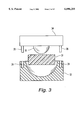
- FIG. 3 is a partial, sectional view of a mold preforming a single cup
- FIG. 4 is a partial, sectional view of molds preforming outer layer cups according to the present invention.
- FIG. 5 is a sectional view of molds and joining cups of a core outer layer
- FIG. 6 is a sectional view of the cups of FIG. 5;
- FIGS. 7 and 8 are sectional views of cups with other embodiments of the mating surfaces shown in FIG. 6;
- FIG. 9 illustrates a compression mold forming a cover around a golf ball core
- FIG. 10 shows an injection mold forming a cover around a core
- FIG. 11 is a flow chart of the method of forming a two-layer core according to the present invention.
- FIG. 12 is a top view of a lower mold plate according to the invention.
- FIG. 12A is a side view of the lower mold plate of FIG. 12;
- FIG. 13 is a top view of an upper mold plate according to the invention.
- FIG. 13A is a side view of the upper mold plate of FIG. 13;
- FIG. 14 is a top view of a center mold plate according to the invention.
- FIG. 14A is a side view of the center mold plate of FIG. 14.
- ball 10 includes a cover 11 and a core 12.
- the core 12 has a center or inner sphere 13 that is disposed concentrically therein and can be comprised of a fluid center 14 in a cavity within an inner layer 15.
- the core 12 also has an outer layer 16, which surrounds the center 13.
- ball 10 includes a cover 11 and a core 12.
- the core 12 has a center or inner sphere 13 that is disposed concentrically therein and which preferably comprises a solid sphere as set forth below.
- the core 12 also has an outer layer 16, which surrounds the center 13.
- the cover 11 provides the interface between the ball 10 and a club and other objects such as trees, cart paths, and grass.
- Properties that are desirable for the cover are good moldability, high abrasion resistance, high tear strength, high resilience, and good mold release, among others.
- the cover 11 can be comprised of polymeric materials such as ionic copolymers of ethylene and an unsaturated monocarboxylic acid, which are available under the trademark "SURLYN” of E.I. DuPont De Nemours & Company of Wilmington, Del. or “IOTEK” or “ESCOR” from Exxon. These are copolymers or terpolymers of ethylene and methacrylic acid or acrylic acid partially neutralized with zinc, sodium, lithium, magnesium, potassium, calcium, manganese, nickel or the like.
- polymeric materials such as ionic copolymers of ethylene and an unsaturated monocarboxylic acid, which are available under the trademark "SURLYN" of E.I. DuPont De Nemours & Company of Wilmington, Del. or “IOTEK” or “ESCOR” from Exxon. These are copolymers or terpolymers of ethylene and methacrylic acid or acrylic acid partially neutralized with zinc, sodium, lithium, magnesium, potassium, calcium, manganese
- the cover 11 has a thickness to generally provide sufficient strength, good performance characteristics and durability.
- the cover 11 is of a thickness from about 0.03 inches to about 0.12 inches. More preferably, the cover 11 is about 0.04 to 0.09 inches in thickness and, most preferably, is about 0.05 to 0.085 inches in thickness.
- the cover 11 can be formed from mixtures or blends of zinc, lithium and/or sodium ionic copolymers or terpolymers.
- the Surlyn® resins for use in the cover 11 are ionic copolymers or terpolymers in which sodium, lithium or zinc salts are the reaction product of an olefin having from 2 to 8 carbon atoms and an unsaturated monocarboxylic acid having 3 to 8 carbon atoms.
- the carboxylic acid groups of the copolymer may be totally or partially neutralized and might include methacrylic, crotonic, maleic, fumaric or itaconic acid.
- This invention can likewise be used in conjunction with homopolymeric and copolymer materials such as:
- vinyl resins such as those formed by the polymerization of vinyl chloride, or by the copolymerization of vinyl chloride with vinyl acetate, acrylic esters or vinylidene chloride.
- Polyolefins such as polyethylene, polypropylene, polybutylene and copolymers such as ethylene methylacrylate, ethylene ethylacrylate, ethylene vinyl acetate, ethylene methacrylic or ethylene acrylic acid or propylene acrylic acid and copolymers and homopolymers produced using single-site catalyst.
- Polyamides such as poly(hexamethylene adipamide) and others prepared from diamines and dibasic acids, as well as those from amino acids such as poly (caprolactam), and blends of polyamides with Surlyn, polyethylene, ethylene copolymers, ethyl-propylene-non-conjugated diene terpolymer, etc.
- Thermoplastics such as the urethanes, olefinic thermoplastic rubbers such as blends of polyolefins with ethylene-propylene-non-conjugated diene terpolymer, block copolymers of styrene and butadiene, isoprene or ethylene-butylene rubber, or copoly (ether-amide), such as PEBAX sold by ELF Atochem.
- Thermoplastic polyesters such as polyethylene terephtha late, polybutylene terephtha late, polyethylene terephthalate/glycol modified and elastomers sold under the trademarks "Hytrel” by E.I. DuPont De Nemours & Company of Wilmington, Del. and "Lomod” by General Electric Company, Pittsfield, Mass.
- Blends and alloys including polycarbonate with acrylonitrile butadiene styrene, polybutylene terephthalate, polyethylene terephithalate, styrene maleic anhydride, polyethylene, elastomers, etc. and polyvinyl chloride with acrylonitrile butadiene styrene or ethylene vinyl acetate or other elastomers.
- the cover 11 is comprised of polymers such as ethylene, propylene, butene-1 or hexane-1 based homopolymers and copolymers including functional monomers such as acrylic and methacrylic acid and fully or partially neutralized ionomer resins and their blends, methyl acrylate, methyl methacrylate homopolymers and copolymers, imidized, amino group containing polymers, polycarbonate, reinforced polyamides, polyphenylene oxide, high impact polystyrene, polyether ketone, polysulfone, poly (phenylene sulfide), acrylonitrile-butadiene, acrylic-styrene-acrylonitrile, poly (ethylene terephthalate), poly (butylene terephthalate), poly (ethylene vinyl alcohol), poly (tetrafluoroethylene) and their copolymers including functional comonomers and blends thereof.
- polymers such as ethylene, propylene, butene-1 or hexane-1
- the cover 11 is preferably comprised of a polyether or polyester thermoplastic urethane, a thermoset polyurethane, a low modulus ionomer such as acid-containing ethylene copolymer ionomers, including E/X/Y terpolymers where E is ethylene, X is an acrylate or methacrylate-based softening comonomer present in 0-50 weight percent and Y is acrylic or meterylic acid present in 5-35 weight percent. More preferably, in a low spin rate embodiment designed for maximum distance, the acrylic or methacrylic acid is present in 15-35 weight percent, making the ionomer a high modulus ionomer. In a high spin embodiment, the acid is present in 10-15 weigh percent or a blend of a low modulus ionomer with a standard ionomer is used.
- a low modulus ionomer such as acid-containing ethylene copolymer ionomers, including E/X/Y terpoly
- the outer layer 16 of the core is preferably made of thermoset rubber base materials, including those conventionally employed in golf ball cores.
- the conventional materials for such cores include compositions having a base rubber, a crosslinking agent, a filler and a co-crosslinking agent.
- the base rubber is typically a synthetic rubber like 1,4-polybutadiene having a cis-structure of at least 40%. Natural rubber, polyisoprene rubber and/or styrene-butadiene rubber may optionally be added to the 1,4-polybutadiene.
- the initiator included in the core composition can be any polymerization initiator which decomposes during the cure cycle.
- the crosslinking agent includes a metal salt of an unsaturated fatty acid such as sodium, zinc, lithium or magnesium salt or an unsaturated fatty acid having 3 to 8 carbon atoms such as acrylic or methacrylic acid.
- the filler typically includes materials such as zinc oxide, barium sulfate, silica, calcium carbonate, zinc carbonate, regrind and the like.
- the outer layer 16 may be comprised of thermoplastic elastomers such as a thermoplastic polyesterester, thermoplastic polyetherester, dynamically vulcanized thermoplastic elastomers, functionalized styrene-butadiene elastomers, thermoplastic urethanes or metallocene polymers or blends thereof.
- thermoplastic elastomers such as a thermoplastic polyesterester, thermoplastic polyetherester, dynamically vulcanized thermoplastic elastomers, functionalized styrene-butadiene elastomers, thermoplastic urethanes or metallocene polymers or blends thereof.
- the present invention is not limited to a particular outer layer 16 material, and the materials are well known to those of ordinary skill in the art.
- the present invention is generally directed to the use of a standard thermoset material, but those of ordinary skill will easily know how to convert the process for using thermoplastic materials.
- the outer layer 16 preferably has an outside diameter in the range of 80 to 98% of the finished ball diameter and an inner diameter in the range of 30 to 70% of the finished ball diameter.
- the outer layer 16 has an inner diameter of approximately 0.8 to 1.5 inches and, more preferably, an inner diameter of approximately 1.0 to 1.3 inches.
- the outer layer 16 has an inner diameter of approximately 1.1-1.2 inches.
- the outer layer 16 has an outside diameter in the range of 1.3 to 1.7 inches and, more preferably, approximately 1.5 to 1.6 inches.
- a golf ball incorporating these measurements can be designed with the various attributes discussed below, such as specific gravity, resiliency and hardness, to provide the desired playing characteristics, such as spin rate and initial velocity.
- the center 13 is either a solid center or a fluid-filled center.
- a first cup 30 is formed as shown in FIG. 3, by compression molding cup or material 31, preferably polybutadiene, between a first substantially hemispherical concave mold part 32 and a protrusive mold part 34.
- the protrusive mold part 34 has a first substantially hemispherical protrusion 35 that faces the first concave mold part 32.
- the protrusive mold part 34 includes a plurality of alignment pins 28 that mate with a plurality of bores 29 in the concave mold part 32.
- the pins 28 align with the bores 29 to make sure that the hemispherical protrusion 35 is concentric or coaxially aligns with the concave mold part 32.
- a second cup 30 (as shown in FIG. 5) is then made in the same manner.
- the two cups 30 are simultaneously compression molded about a single protrusive mold part 36 that has first and second protrusions 35 and 37 respectively.
- the mold part 36 further includes non-planar surfaces 38 and 39.
- the surface 38 contains a tongue pattern that circumscribes the protrusions 35.
- the surface 39 includes a groove that circumscribes the protrusion 37.
- First and second hemispherical concave mold parts 32 and 33 are positioned opposite each other and protrusive mold part 36 is placed between the concave mold parts 32 and 33.
- Alignment pins 28 mate with the alignment bores 29 to make sure that the protrusions 35 and 37 are concentric or coaxially aligned with the concave mold parts.
- material 31 includes more material than that necessary to form the cups. For example, it is preferable to use 20% more material than necessary.
- FIG. 5 shows two concave mold parts 32 and 33 after cups 30 have been molded.
- Each hemispherical cup 30 has a hemispherical cavity 44.
- the cups 30 Disposed around the cavities 44, the cups 30 have mating surfaces 46a and 46b, which are substantially non-planar in this embodiment.
- the non-planar surfaces 46a and 46b of the cups are molded to each have a pattern concentric with each cup.
- the surface 46a includes a tongue 47a due to the groove 39 in the mold part 36.
- the surface 46b includes a groove 47b due to the tongue 38 in the mold part 36.
- the mating surfaces 46a and 46b are arranged to mesh with each other so that the tongue 47a engages the groove 47b.
- the center 13 is placed in the cups 30, and the two cups 30 are joined.
- Cups 30 are preferably kept in their respective hemispherical molds 32 and 33 during this step.
- the cups are compressed together at an elevated temperature and high pressure and the excess material of each cup flows, mixes together and crosslinks. Since the temperature during this step is raised above the cure activation temperature of the cup material, the material crosslinks.
- joining the cups may be achieved by removing protrusive mold part 36 and running the compression mold through a second cycle, heating and compressing the cups 30 together.
- an adhesive 42 can be applied such that it bonds the center 13 to the cups 30.
- the adhesive 42 is placed within the cup cavities 44 and the adhesive 42 is spread evenly on the center 13 upon joining the cups 30 to one another.
- a preferred adhesive for use with polybutadiene cups 30 is an epoxy, formed by blending low viscosity liquid resins, and formulated to be flexible in its cured state.
- a suitable epoxy is formed by mixing an approximately 1:1 volume ratio of about 83 parts by weight of AB-82 hardener into 100 parts by weight of Epoxy Resin #1028, both of which are sold by RBC Industries, Inc. In its liquid state, the epoxy is ideal for use in metering, mixing, and dispensing equipment. This epoxy is preferably cured at 77° F. for 18 to 24 hours, at 95° F. for 6 hours, at 120° F. for 3 hours, or at 150° F. for 1 hour. The cured adhesive's physical properties resemble those of elastomeric urethane.
- the Shore D hardness of the cured adhesive is within 20 Shore D of the hardness of the elastomeric cup material.
- FIGS. 7 and 8 show other embodiments of cups 48 and 54, respectively, that have mating surfaces similar to the cups 30 of FIG. 6.
- cups 48 have non-planar mating surfaces 50 and 52
- cups 54 have substantially flat mating surfaces 56 and 58.
- the surfaces 50 and 52 each have a circular pattern of ridges that is preferably symmetrical about the cavity 44 of each cup 48. The patterns shown are concentric with the cups 48.
- the non-planar surfaces 50 and 52 are arranged to mesh with each other. The non-planar mating surfaces are most useful when an adhesive is used to bond the cups together.
- FIG. 9 illustrates a step of compression molding two halves 70 of a cover 11 around the core 12 in a dimpled mold 68.
- FIG. 10 shows a step of injection molding the cover material around the core 12 in a dimpled mold 60 with retractable pins 62 that position the core 12 within the dimpled mold 60 and retract before the cover 11 solidifies or cools completely.
- the most preferred molding process for forming the centers uses a mold assembly 100 comprising a lower or bottom mold plate 101, an upper or top mold plate 102 and a center mold plate 103.
- the bottom and top mold plates 101 and 102 include a plurality of mating cavities 104 and 105 that form a sphere, which is the size of a golf ball core as set forth above.
- the center mold plate 103 includes a plurality of protrusions 106 on opposite sides of the center mold plate for corresponding with the cavities 104 and 105 of the top and bottom mold plates.
- the protrusions 106 are hemispheres that are substantially the same size as half of the ball center as set forth above.
- Step 1 the core outer layer material 107, such as polybutadiene, is placed in the cavities 104 and 105 of the bottom and top mold plate.
- Step 2A the center mold plate 103 is moved into alignment with the top mold plate 102 such that the protrusions 106 are located in alignment or coaxial with the cavities 105.
- the center mold plate 103 is positioned over the top mold plate 102 at such a height that the polybutadiene material is only compressed enough to hold the material in place.
- Step 2B and 2C the center mold plate 103 and the top mold plate 102 are moved into alignment with the bottom mold plate 101 such that the protrusions 106 and the cavities 104 and 105 are all in alignment.
- the center plate 103 is spaced from the bottom mold plate 101 such that the material in the bottom mold plate cavities 104 is only slightly compressed. Thus, a folded assembly is formed.
- the folded assembly 100 is placed into a press, heated and compressed, as shown in Step 3.
- the folded assembly 100 is heated to a first temperature that makes the polybutadiene material significantly more pliable, but is below the cure activation temperature.
- the temperature is greater than about 150° F., but less that the cure activation temperature.
- the most preferred temperature is between about 190° F. and 220° F.
- the folded assembly 100 is compressed to a pressure sufficient enough to form hemispheres from the polybutadiene material, as shown in Step 4.
- the mold assembly is compressed using a hydraulic preforming pressure of about 230 psi.
- the pressure per cavity is about 675 pounds of force per cavity.
- the mold is then cooled with cooling water that has a temperature between about 60° F. to 100° F. and preferably the cooling water has a temperature of about 80° F.
- the mold assembly is removed from the press and the bottom mold plate 101, top mold plate 102 and the center mold plate 103 are moved out of alignment, as shown in Step 4. Then, turning to Step 5, the ball centers 13 are placed within the hemispherical cups 30 located in the top mold plate 102.
- the bottom mold plate 101 is moved into alignment with the top mold plate 102 such that the outer layer hemispherical cups 30 form a sphere around the ball centers 13.
- the top and bottom mold plates 101 and 102 are placed back into the press, heated and compressed again. This time, the bottom and top mold plates are heated to a temperature above the cure activation temperature of the cups.
- the mold plates are heated to a temperature of greater than about 290° F.
- the mold plates are compressed using a hydraulic preforming pressure of about 2000 psi.
- a 28 inch diameter ram for the press that produces 1,231,000 pounds of force on a mold with 210 cavities, the pressure per cavity is about 6000 pounds of force per cavity.
- one of ordinary skill in the art can vary the pressure.
- the top mold plate 102 and bottom mold plate 101 are comprised of a plurality of hemispherical cavities 105 and 104.
- the cavities 104 and 105 are formed directly in the mold plates 101 and 102 or are comprised of replaceable mold cavities as set forth in U.S. Pat. No. 4,508,309, which issued to Brown (referred to hereafter as "the Brown patent").
- the cavities 104 and 105 are formed with a radius substantially equal to the finished core radius. Preferably, this is in the range of about 1.50 inches to 1.65 inches as set forth above.
- Surrounding each of the cavities is a circumferential groove 107 for surplus outer layer material.
- the center mold plate 103 includes the protrusions or buttons 106 as set forth above.
- the protrusions 106 are replaceable so that different sized cavities can be formed in the outer layer cups to accommodate different sized centers.
- the protrusions can be easily cleaned or replaced after wear.
- the mold plates are movable in and out of the mold press, the mold plates do not have flow channels like that described in the Brown patent.
- the mold plates are preferably made thin to reduce thermal mass and thermal response time, i.e., the mold plates have a thickness of less that about 1.5 times the cavity radius.
- the top mold plate 102 In order to position the top mold plate 102 in alignment with the bottom mold plate 101 and the center mold plate 103, the top mold plate 102 includes at least two pins 108 and at least two apertures 109 for receiving pins (best shown in FIGS. 12 and 12A). In the most preferred embodiment, there are four locations forming a rectangle on the top mold plate 102. The pins 108 are located diagonally across from each other at two of the locations and the apertures 109 are also diagonally across from each other at the other two locations. More preferably, the pin and aperture locations are positioned near the outside edge of the top mold plate 102.
- the bottom mold plate 101 also includes two pins 110 and two apertures 111 located at similar positions to those on the top mold plate.
- the pins 110 insert into the apertures 109 and the pins 108 insert into the apertures 111 to position the mold plates relative to each other.
- the center mold plate 103 includes four apertures 112 such that when it is located between the top and bottom mold plates the pins 108 and 110 insert into the apertures 112 to properly position all of the mold plates relative to one another.
- the top mold plate 102 includes linking arms 113 and 115 that extend laterally from the sides of the mold plate.
- the arms 113 include a first lateral portion 117 and a second vertical portion 118.
- the vertical portion 118 defines a first vertical slot 119 therein.
- the slot 119 has a length that is sufficient to reach the bottom mold plate 101 when the center mold plate 103 is positioned between the bottom mold plate 101 and top mold plate 102.
- the vertical portion 118 further defines a second vertical slot 126.
- the arms 115 are comprised of a first lateral portion 120 and a vertical portion 121.
- the vertical portion defines a vertical slot 122.
- the bottom mold plate 101 includes linking arms 114 that extend laterally from the sides of the mold plate.
- the center mold plate 103 includes linking arms 116 and 125 extending laterally from opposite sides of the plate.
- the arms 114, 116, and 125 define apertures associated with the slots in the top mold plate 102.
- the top mold plate arms 113 are coupled to the bottom mold plate arms 114 and the center mold plate arms 125.
- the top mold plate arms 115 are coupled to the center mold plate arms 116. The arms are coupled using the slot 119, apertures, and pin 120a.
- the slot 119 provides the coupling between the mold plates and allows for the vertical motion of the mold plates relative to each other when they are compressed during molding.
- apertures in the arm members 125 align with the second vertical slot 126 in arm 113 and a pin 120b can be inserted therein to lock the plates together before they are folded over the bottom mold plate 101.
- a plurality of spring members 123 are positioned on the top mold plate 102.
- a plurality of spring members 122 are positioned on the bottom mold plate 101.
- the spring members 123 are located between the top mold plate 102 and the center mold plate 103.
- the spring members 122 are located between the center mold plate 103 and the bottom mold plate 101.
- the spring members 122, 123 keep the mold plates from compressing against each other prior to being compressed during the molding cycles, and ensure that the plates are parallel prior to closing.
- the spring members are sized such that they are sufficient to hold the weight of the mold plates, but do not provide significant resistance during the mold compression during the molding process.
- the mold plates 101, 102 and 103 can include handles 124 to facilitate the manual insertion and retrieval from the mold press or other members that can be used for automated processes.
Abstract
Description
Claims (10)
Priority Applications (4)
| Application Number | Priority Date | Filing Date | Title |
|---|---|---|---|
| US09/188,893 US6096255A (en) | 1996-03-11 | 1998-11-10 | Method for making multi-layered golf ball |
| AU18160/00A AU1816000A (en) | 1998-11-10 | 1999-11-09 | Method for making multi-layered golf ball |
| JP2000580706A JP4058242B2 (en) | 1998-11-10 | 1999-11-09 | Multilayer golf ball manufacturing method |
| PCT/US1999/026571 WO2000027481A1 (en) | 1998-11-10 | 1999-11-09 | Method for making multi-layered golf ball |
Applications Claiming Priority (3)
| Application Number | Priority Date | Filing Date | Title |
|---|---|---|---|
| US08/615,346 US5683312A (en) | 1996-03-11 | 1996-03-11 | Fluid or liquid filled non-wound golf ball |
| US90235197A | 1997-07-29 | 1997-07-29 | |
| US09/188,893 US6096255A (en) | 1996-03-11 | 1998-11-10 | Method for making multi-layered golf ball |
Related Parent Applications (1)
| Application Number | Title | Priority Date | Filing Date |
|---|---|---|---|
| US90235197A Continuation-In-Part | 1996-03-11 | 1997-07-29 |
Publications (1)
| Publication Number | Publication Date |
|---|---|
| US6096255A true US6096255A (en) | 2000-08-01 |
Family
ID=22694999
Family Applications (1)
| Application Number | Title | Priority Date | Filing Date |
|---|---|---|---|
| US09/188,893 Expired - Lifetime US6096255A (en) | 1996-03-11 | 1998-11-10 | Method for making multi-layered golf ball |
Country Status (4)
| Country | Link |
|---|---|
| US (1) | US6096255A (en) |
| JP (1) | JP4058242B2 (en) |
| AU (1) | AU1816000A (en) |
| WO (1) | WO2000027481A1 (en) |
Cited By (27)
| Publication number | Priority date | Publication date | Assignee | Title |
|---|---|---|---|---|
| WO2001012409A1 (en) * | 1999-08-17 | 2001-02-22 | Acushnet Company | Method and apparatus for making multi-layered cores or golf balls |
| US6290797B1 (en) * | 1999-04-02 | 2001-09-18 | Acushnet Company | Process for making multi-layer core golf balls |
| WO2002045935A1 (en) * | 2000-12-06 | 2002-06-13 | Spalding Sports Worldwide, Inc. | Mini-ball insertion mechanism for forming golf ball cores |
| US20030114248A1 (en) * | 2001-05-01 | 2003-06-19 | Morgan William E. | Wound golf balls with high specific gravity centers |
| US6582215B2 (en) * | 2001-04-11 | 2003-06-24 | Spalding Sports Worldwide, Inc. | Automatic slug feeder for golf ball core forming apparatus |
| US20030131921A1 (en) * | 1996-03-11 | 2003-07-17 | Boehm Herbert C. | Method for making a multilayered golf ball |
| WO2003068476A1 (en) * | 2002-02-11 | 2003-08-21 | Spalding Sports Worldwide, Inc. | Molding processes and equipment for forming golf balls |
| US6644948B2 (en) | 2001-06-18 | 2003-11-11 | Acushnet Company | Mold-half |
| US20040017027A1 (en) * | 2002-07-25 | 2004-01-29 | Vora Ajay P. | Method of heating golf ball components by radio frequency |
| US20040058029A1 (en) * | 2002-09-19 | 2004-03-25 | Vargas Manuel G. | Golf ball core mold with improved ejector |
| US20040232577A1 (en) * | 2003-05-21 | 2004-11-25 | William Brum | Method and apparatus for molding dual core assemblies |
| US20050069600A1 (en) * | 2003-09-26 | 2005-03-31 | Scolamiero Stephen K. | Platen for improved molding |
| US20050171221A1 (en) * | 2004-02-04 | 2005-08-04 | Danner Richard S. | Method for drying and using swarf in golf balls |
| US20050272867A1 (en) * | 2004-06-07 | 2005-12-08 | Hogge Matthew F | Non-ionomeric silane crosslinked polyolefin golf ball layers |
| US20050269737A1 (en) * | 2004-06-07 | 2005-12-08 | Hogge Matthew F | Non-ionomeric silane crosslinked polyolefin golf ball layers |
| US20060017201A1 (en) * | 2004-07-26 | 2006-01-26 | Acushnet Company | Method for molding castable light stable polyurethane and polyurea golf balls |
| US20100003357A1 (en) * | 2008-07-07 | 2010-01-07 | Ajay Vora | Golf ball mold |
| US8425351B2 (en) | 2010-04-30 | 2013-04-23 | Callaway Golf Company | Golf ball having deflection differential between inner core and dual core |
| WO2013084045A1 (en) * | 2011-12-05 | 2013-06-13 | Nike International Ltd. | Method for compression molding a dual core for a golf ball |
| US9211662B2 (en) | 2012-03-30 | 2015-12-15 | Nike, Inc. | Mold with midplate and method of molding golf ball |
| US20160354954A1 (en) * | 2015-06-03 | 2016-12-08 | Novation Iq Llc | System and method for making hollow foam balls and other molded objects |
| US9713748B2 (en) | 2015-11-17 | 2017-07-25 | Acushnet Company | Golf ball with excellent interlayer adhesion between adjacent differing layers |
| US20170338202A1 (en) * | 2016-05-17 | 2017-11-23 | Taiwan Semiconductor Manufacturing Company, Ltd. | Advanced INFO POP and Method of Forming Thereof |
| TWI630096B (en) * | 2016-06-21 | 2018-07-21 | 克力威高爾夫公司 | Method and apparatus for molding dual cores for a golf ball |
| US10046210B1 (en) * | 2017-05-24 | 2018-08-14 | Acushnet Company | Golf ball incorporating pair of thin hemispherical cups having targeted configuration/geometry and being compression molded about large, soft subassembly/core |
| US10486029B2 (en) | 2015-11-17 | 2019-11-26 | Acushnet Company | Golf ball displaying improved adhesion between TiO2-pigmented layer incorporating silane-containing adhesion promoter and an adjacent differing layer |
| US11602874B2 (en) * | 2019-12-05 | 2023-03-14 | Bridgestone Sports Co., Ltd. | Multilayer core molding method |
Families Citing this family (3)
| Publication number | Priority date | Publication date | Assignee | Title |
|---|---|---|---|---|
| US20100112254A1 (en) * | 2007-03-21 | 2010-05-06 | Data F. S.R.L. | Coloured playing bowl |
| US20130072323A1 (en) * | 2011-09-21 | 2013-03-21 | Nike, Inc. | Method Of Golf Ball Compression Molding |
| US8974218B2 (en) * | 2012-04-26 | 2015-03-10 | Nike, Inc. | Mold plate and method of molding golf ball core |
Citations (4)
| Publication number | Priority date | Publication date | Assignee | Title |
|---|---|---|---|---|
| US1505816A (en) * | 1922-07-17 | 1924-08-19 | Miller Rubber Co | Mold for vulcanizing hollow articles |
| US3933967A (en) * | 1973-02-20 | 1976-01-20 | Taylor Don A | Method of making seamless hollow molded articles |
| US5098104A (en) * | 1991-06-17 | 1992-03-24 | Kane Pat E | Water soluble golf ball |
| US5150906A (en) * | 1989-03-10 | 1992-09-29 | Lisco, Inc. | Multi-piece golf balls and methods of manufacture |
-
1998
- 1998-11-10 US US09/188,893 patent/US6096255A/en not_active Expired - Lifetime
-
1999
- 1999-11-09 WO PCT/US1999/026571 patent/WO2000027481A1/en active Application Filing
- 1999-11-09 AU AU18160/00A patent/AU1816000A/en not_active Abandoned
- 1999-11-09 JP JP2000580706A patent/JP4058242B2/en not_active Expired - Fee Related
Patent Citations (4)
| Publication number | Priority date | Publication date | Assignee | Title |
|---|---|---|---|---|
| US1505816A (en) * | 1922-07-17 | 1924-08-19 | Miller Rubber Co | Mold for vulcanizing hollow articles |
| US3933967A (en) * | 1973-02-20 | 1976-01-20 | Taylor Don A | Method of making seamless hollow molded articles |
| US5150906A (en) * | 1989-03-10 | 1992-09-29 | Lisco, Inc. | Multi-piece golf balls and methods of manufacture |
| US5098104A (en) * | 1991-06-17 | 1992-03-24 | Kane Pat E | Water soluble golf ball |
Cited By (50)
| Publication number | Priority date | Publication date | Assignee | Title |
|---|---|---|---|---|
| US20030131921A1 (en) * | 1996-03-11 | 2003-07-17 | Boehm Herbert C. | Method for making a multilayered golf ball |
| US6797097B2 (en) * | 1996-03-11 | 2004-09-28 | Acushnet Company | Method for making a multilayered golf ball |
| US6290797B1 (en) * | 1999-04-02 | 2001-09-18 | Acushnet Company | Process for making multi-layer core golf balls |
| US6303065B1 (en) | 1999-08-17 | 2001-10-16 | Acushnet Company | Method and apparatus for making multi-layered cores or golf balls |
| US20020017737A1 (en) * | 1999-08-17 | 2002-02-14 | Reid Walter L. | Method and apparatus for making multi-layered cores or golf balls |
| WO2001012409A1 (en) * | 1999-08-17 | 2001-02-22 | Acushnet Company | Method and apparatus for making multi-layered cores or golf balls |
| US6645414B2 (en) | 1999-08-17 | 2003-11-11 | Acushnet Company | Method for making multi-layered cores for golf balls |
| US20030207728A1 (en) * | 1999-08-17 | 2003-11-06 | Reid Walter L. | Multi-layered cores or golf balls |
| GB2386089A (en) * | 2000-12-06 | 2003-09-10 | Spalding Sports Worldwide Inc | Mini-ball insertion mechanism for forming golf ball cores |
| US6436327B1 (en) | 2000-12-06 | 2002-08-20 | Spalding Sports Worldwide, Inc. | Mini-ball insertion mechanism for forming golf ball cores |
| GB2386089B (en) * | 2000-12-06 | 2004-11-10 | Spalding Sports Worldwide Inc | Mini-ball insertion mechanism for forming golf ball cores |
| WO2002045935A1 (en) * | 2000-12-06 | 2002-06-13 | Spalding Sports Worldwide, Inc. | Mini-ball insertion mechanism for forming golf ball cores |
| US6582215B2 (en) * | 2001-04-11 | 2003-06-24 | Spalding Sports Worldwide, Inc. | Automatic slug feeder for golf ball core forming apparatus |
| US20030114248A1 (en) * | 2001-05-01 | 2003-06-19 | Morgan William E. | Wound golf balls with high specific gravity centers |
| US6986717B2 (en) | 2001-05-01 | 2006-01-17 | Acushnet Company | Wound golf balls with high specific gravity centers |
| US6644948B2 (en) | 2001-06-18 | 2003-11-11 | Acushnet Company | Mold-half |
| US20040239000A1 (en) * | 2001-12-04 | 2004-12-02 | Callaway Golf Company | Molding processes and equipment for forming golf balls |
| US7329375B2 (en) * | 2001-12-04 | 2008-02-12 | Callaway Golf Company | Process for forming portions of a golf ball cover |
| US6769900B2 (en) * | 2001-12-04 | 2004-08-03 | Callaway Golf Company | Molding processes and equipment for forming golf balls |
| WO2003068476A1 (en) * | 2002-02-11 | 2003-08-21 | Spalding Sports Worldwide, Inc. | Molding processes and equipment for forming golf balls |
| US20040017027A1 (en) * | 2002-07-25 | 2004-01-29 | Vora Ajay P. | Method of heating golf ball components by radio frequency |
| US20050133966A1 (en) * | 2002-07-25 | 2005-06-23 | Vora Ajay P. | Method of heating golf ball components by radio frequency |
| US20040058029A1 (en) * | 2002-09-19 | 2004-03-25 | Vargas Manuel G. | Golf ball core mold with improved ejector |
| US20040232577A1 (en) * | 2003-05-21 | 2004-11-25 | William Brum | Method and apparatus for molding dual core assemblies |
| US7407378B2 (en) | 2003-05-21 | 2008-08-05 | Acushnet Company | Method and apparatus for molding dual core assemblies |
| US7335326B2 (en) * | 2003-05-21 | 2008-02-26 | Acushnet Company | Method and Apparatus for molding dual core assemblies |
| US20060141087A1 (en) * | 2003-05-21 | 2006-06-29 | Acushnet Company | Method and apparatus for molding dual core assemblies |
| US20050069600A1 (en) * | 2003-09-26 | 2005-03-31 | Scolamiero Stephen K. | Platen for improved molding |
| US20050171221A1 (en) * | 2004-02-04 | 2005-08-04 | Danner Richard S. | Method for drying and using swarf in golf balls |
| US7148262B2 (en) | 2004-02-04 | 2006-12-12 | Acushnet Company | Method for drying and using swarf in golf balls |
| US20050272867A1 (en) * | 2004-06-07 | 2005-12-08 | Hogge Matthew F | Non-ionomeric silane crosslinked polyolefin golf ball layers |
| US8883057B2 (en) | 2004-06-07 | 2014-11-11 | Acushnet Company | Non-ionomeric silane crosslinked polyolefin golf ball layers |
| US20050269737A1 (en) * | 2004-06-07 | 2005-12-08 | Hogge Matthew F | Non-ionomeric silane crosslinked polyolefin golf ball layers |
| US7279529B2 (en) | 2004-06-07 | 2007-10-09 | Acushnet Company | Non-ionomeric silane crosslinked polyolefin golf ball layers |
| US20060017201A1 (en) * | 2004-07-26 | 2006-01-26 | Acushnet Company | Method for molding castable light stable polyurethane and polyurea golf balls |
| US7481956B2 (en) | 2004-07-26 | 2009-01-27 | Acushnet Company | Method for molding castable light stable polyurethane and polyurea golf balls |
| US20100003357A1 (en) * | 2008-07-07 | 2010-01-07 | Ajay Vora | Golf ball mold |
| US8425351B2 (en) | 2010-04-30 | 2013-04-23 | Callaway Golf Company | Golf ball having deflection differential between inner core and dual core |
| US8980151B2 (en) | 2011-12-05 | 2015-03-17 | Nike, Inc. | Method for compression molding a dual core for a golf ball |
| WO2013084045A1 (en) * | 2011-12-05 | 2013-06-13 | Nike International Ltd. | Method for compression molding a dual core for a golf ball |
| US9211662B2 (en) | 2012-03-30 | 2015-12-15 | Nike, Inc. | Mold with midplate and method of molding golf ball |
| US20160354954A1 (en) * | 2015-06-03 | 2016-12-08 | Novation Iq Llc | System and method for making hollow foam balls and other molded objects |
| US9878474B2 (en) * | 2015-06-03 | 2018-01-30 | Novation Iq Llc | System and method for making hollow foam balls and other molded objects |
| US9713748B2 (en) | 2015-11-17 | 2017-07-25 | Acushnet Company | Golf ball with excellent interlayer adhesion between adjacent differing layers |
| US10486029B2 (en) | 2015-11-17 | 2019-11-26 | Acushnet Company | Golf ball displaying improved adhesion between TiO2-pigmented layer incorporating silane-containing adhesion promoter and an adjacent differing layer |
| US10814183B2 (en) | 2015-11-17 | 2020-10-27 | Acushnet Company | Golf ball displaying improved adhesion between TiO2-pigmented layer incorporating silane-containing adhesion promoter and an adjacent differing layer |
| US20170338202A1 (en) * | 2016-05-17 | 2017-11-23 | Taiwan Semiconductor Manufacturing Company, Ltd. | Advanced INFO POP and Method of Forming Thereof |
| TWI630096B (en) * | 2016-06-21 | 2018-07-21 | 克力威高爾夫公司 | Method and apparatus for molding dual cores for a golf ball |
| US10046210B1 (en) * | 2017-05-24 | 2018-08-14 | Acushnet Company | Golf ball incorporating pair of thin hemispherical cups having targeted configuration/geometry and being compression molded about large, soft subassembly/core |
| US11602874B2 (en) * | 2019-12-05 | 2023-03-14 | Bridgestone Sports Co., Ltd. | Multilayer core molding method |
Also Published As
| Publication number | Publication date |
|---|---|
| JP4058242B2 (en) | 2008-03-05 |
| AU1816000A (en) | 2000-05-29 |
| WO2000027481A1 (en) | 2000-05-18 |
| JP2002529163A (en) | 2002-09-10 |
Similar Documents
| Publication | Publication Date | Title |
|---|---|---|
| US6096255A (en) | Method for making multi-layered golf ball | |
| US5919100A (en) | Fluid or liquid filled non-wound golf ball | |
| US6290797B1 (en) | Process for making multi-layer core golf balls | |
| US6468381B1 (en) | Method of making a golf ball and golf ball compression mold | |
| US8926452B2 (en) | Multilayer golf ball | |
| US5683312A (en) | Fluid or liquid filled non-wound golf ball | |
| US6685579B2 (en) | Multi-layer cover polyurethane golf ball | |
| US7407378B2 (en) | Method and apparatus for molding dual core assemblies | |
| US20020151382A1 (en) | Three-layer cover for a golf ball including a thin dense layer | |
| US6797097B2 (en) | Method for making a multilayered golf ball | |
| US6773363B2 (en) | Hollow layered golf ball | |
| WO2003068477A1 (en) | Molding processes and equipment for forming golf balls with deep dimples | |
| US6645414B2 (en) | Method for making multi-layered cores for golf balls | |
| US20010008320A1 (en) | Method for molding a golf ball mantle layer | |
| JP3789301B2 (en) | Multi-layer golf ball | |
| US20020137577A1 (en) | Initial velocity dual core golf ball | |
| WO2003068475A1 (en) | Molding processes and equipment for forming golf balls | |
| WO2003068332A1 (en) | Golf ball |
Legal Events
| Date | Code | Title | Description |
|---|---|---|---|
| AS | Assignment |
Owner name: ACUSHNET COMPANY, MASSACHUSETTS Free format text: ASSIGNMENT OF ASSIGNORS INTEREST;ASSIGNORS:BROWN, ROBERT A.;CAVALLARO, CHRISTOPHER;REEL/FRAME:009579/0042 Effective date: 19981106 |
|
| STCF | Information on status: patent grant |
Free format text: PATENTED CASE |
|
| FEPP | Fee payment procedure |
Free format text: PAYOR NUMBER ASSIGNED (ORIGINAL EVENT CODE: ASPN); ENTITY STATUS OF PATENT OWNER: LARGE ENTITY |
|
| FPAY | Fee payment |
Year of fee payment: 4 |
|
| FPAY | Fee payment |
Year of fee payment: 8 |
|
| REMI | Maintenance fee reminder mailed | ||
| AS | Assignment |
Owner name: KOREA DEVELOPMENT BANK, NEW YORK BRANCH, NEW YORK Free format text: SECURITY AGREEMENT;ASSIGNOR:ACUSHNET COMPANY;REEL/FRAME:027346/0075 Effective date: 20111031 |
|
| FPAY | Fee payment |
Year of fee payment: 12 |
|
| AS | Assignment |
Owner name: WELLS FARGO BANK, NATIONAL ASSOCIATION, AS ADMINISTRATIVE AGENT, CALIFORNIA Free format text: SECURITY INTEREST;ASSIGNOR:ACUSHNET COMPANY;REEL/FRAME:039506/0030 Effective date: 20160728 Owner name: WELLS FARGO BANK, NATIONAL ASSOCIATION, AS ADMINIS Free format text: SECURITY INTEREST;ASSIGNOR:ACUSHNET COMPANY;REEL/FRAME:039506/0030 Effective date: 20160728 |
|
| AS | Assignment |
Owner name: ACUSHNET COMPANY, MASSACHUSETTS Free format text: RELEASE OF SECURITY INTEREST IN PATENTS PREVIOUSLY RECORDED AT REEL/FRAME (027346/0075);ASSIGNOR:KOREA DEVELOPMENT BANK, NEW YORK BRANCH;REEL/FRAME:039939/0098 Effective date: 20160728 |
|
| AS | Assignment |
Owner name: JPMORGAN CHASE BANK, N.A., AS SUCCESSOR ADMINISTRATIVE AGENT, ILLINOIS Free format text: ASSIGNMENT OF SECURITY INTEREST IN PATENTS (ASSIGNS 039506-0030);ASSIGNOR:WELLS FARGO BANK, NATIONAL ASSOCIATION, AS RESIGNING ADMINISTRATIVE AGENT;REEL/FRAME:061521/0414 Effective date: 20220802 |