US6101301A - Temperature-compensated optical fiber gratings with fine wavelength tuning - Google Patents
Temperature-compensated optical fiber gratings with fine wavelength tuning Download PDFInfo
- Publication number
- US6101301A US6101301A US09/062,339 US6233998A US6101301A US 6101301 A US6101301 A US 6101301A US 6233998 A US6233998 A US 6233998A US 6101301 A US6101301 A US 6101301A
- Authority
- US
- United States
- Prior art keywords
- grating
- temperature
- optical fiber
- cte
- fiber grating
- Prior art date
- Legal status (The legal status is an assumption and is not a legal conclusion. Google has not performed a legal analysis and makes no representation as to the accuracy of the status listed.)
- Expired - Lifetime
Links
Images


Classifications
-
- G—PHYSICS
- G02—OPTICS
- G02B—OPTICAL ELEMENTS, SYSTEMS OR APPARATUS
- G02B6/00—Light guides; Structural details of arrangements comprising light guides and other optical elements, e.g. couplings
- G02B6/02—Optical fibres with cladding with or without a coating
- G02B6/02057—Optical fibres with cladding with or without a coating comprising gratings
- G02B6/02076—Refractive index modulation gratings, e.g. Bragg gratings
- G02B6/02195—Refractive index modulation gratings, e.g. Bragg gratings characterised by means for tuning the grating
- G02B6/022—Refractive index modulation gratings, e.g. Bragg gratings characterised by means for tuning the grating using mechanical stress, e.g. tuning by compression or elongation, special geometrical shapes such as "dog-bone" or taper
-
- G—PHYSICS
- G02—OPTICS
- G02B—OPTICAL ELEMENTS, SYSTEMS OR APPARATUS
- G02B6/00—Light guides; Structural details of arrangements comprising light guides and other optical elements, e.g. couplings
- G02B6/02—Optical fibres with cladding with or without a coating
- G02B6/02057—Optical fibres with cladding with or without a coating comprising gratings
- G02B6/02076—Refractive index modulation gratings, e.g. Bragg gratings
- G02B6/02171—Refractive index modulation gratings, e.g. Bragg gratings characterised by means for compensating environmentally induced changes
- G02B6/02176—Refractive index modulation gratings, e.g. Bragg gratings characterised by means for compensating environmentally induced changes due to temperature fluctuations
- G02B6/0218—Refractive index modulation gratings, e.g. Bragg gratings characterised by means for compensating environmentally induced changes due to temperature fluctuations using mounting means, e.g. by using a combination of materials having different thermal expansion coefficients
Definitions
- the present invention relates to optical fiber gratings, in particular, dimensionally compact and wavelength-adjustable gratings that are packaged such that the grating reflection wavelength is substantially temperature independent.
- optical fibers are key components in modern telecommunication systems. Basically, optical fibers are thin strands of glass capable of transmitting an optical signal containing a large amount of information over long distances with very low loss.
- an optical fiber is a small diameter waveguide comprising a core having a first index of refraction surrounded by a cladding having a second (lower) index of refraction.
- Typical optical fibers are made of high purity silica with minor concentrations of dopants to control the index of refraction.
- Optical fiber gratings are important elements for selectively controlling specific wavelengths of light within an optical fiber. Such gratings include Bragg gratings and long period gratings.
- Such Bragg gratings have found use in a variety of applications including filtering, stabilization of semiconductor lasers, reflection of fiber amplifier pump energy, and compensation for fiber dispersion.
- Long-period fiber grating devices provide wavelength dependent loss and may be used for spectral shaping.
- a long-period grating couples optical power between two copropagating modes with very low back reflections.
- a long-period grating typically comprises a length of optical fiber wherein a plurality of refractive index perturbations are spaced along the fiber by a periodic distance ⁇ ' which is large compared to the wavelength ⁇ of the transmitted light.
- long-period gratings use a periodic spacing ⁇ ' which is typically at least 10 times larger than the transmitted wavelength, i.e. ⁇ ' ⁇ 10 ⁇ .
- ⁇ ' is in the range 15-1500 micrometers, and the width of a perturbation is in the range 1/5 ⁇ ' to 4/5 ⁇ '.
- the spacing ⁇ ' can vary along the length of the grating.
- Long-period fiber grating devices selectively remove light at specific wavelengths by mode conversion.
- long-period gratings remove light without reflection as by converting it from a guided mode to a non-guided mode.
- a non-guided mode is a mode which is not confined to the core, but rather, is defined by the entire waveguide structure. Often, it is a cladding mode.
- the spacing ⁇ ' of the perturbations is chosen to shift transmitted light in the region of a selected peak wavelength ⁇ p from a guided mode into a nonguided mode, thereby reducing in intensity a band of light centered about the peak wavelength ⁇ p .
- the spacing ⁇ ' can be chosen to shift light from one guided mode to a second guided mode (typically a higher order mode), which is subsequently stripped off the fiber to provide a wavelength dependent loss.
- a second guided mode typically a higher order mode
- Such devices are particularly useful for equalizing amplifier gain at different wavelengths of an optical communication system.
- the temperature-induced shift in the reflection wavelength typically is primarily due to the change in n eff with temperature.
- the thermal expansion-induced change in ⁇ is responsible for only a small fraction of the net temperature dependence of a grating in a conventional SiO 2 -based fiber.
- U.S. Pat. No. 5,042,898 discloses apparatus that can provide temperature compensation of a fiber Bragg grating.
- the apparatus comprises two juxtaposed compensating members that differ with respect to the coefficient of thermal expansion (CTE). Both members have a conventional positive CTE.
- the fiber is rigidly attached to each of the members, with the grating disposed between two attachment points.
- the apparatus can be designed to apply tensile or compressive stress to the grating. In the latter case the grating is confined in a small tube, exemplarily a silica tube.
- temperature compensating packages can have a substantial variation of reflection wavelength from one package to another because of the variability in the grating periodicity as well as minute variations in the degree of pre-stress applied to each grating or minute variations in the attachment locations.
- a temperature compensated optical fiber grating device comprises a longitudinally extending optical fiber grating having a length and a packaging assembly for the grating comprising a first longitudinally extending body of material having a first coefficient of thermal expansion (CTE) and second and third longitudinally extending bodies of material having CTE's lower than the first CTE.
- the three bodies are mechanically attached at alternate ends to form a composite structure having an effective negative CTE between two ends to which the grating is attached.
- the resulting grating device can be made in compact form having an overall length less than 30% more than the grating (and preferably less than 10%) and can reduce the temperature dependent wavelength change in the grating to less than 0.2 nm/100° C. and preferably less than 0.05 nm/100° C.
- the packaging bodies include a cylinder enclosing the grating.
- FIG. 1 schematically illustrates a first embodiment of a fiber grating in a temperature compensating package
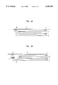
- FIGS. 2A and 2B schematically describe alternative embodiments utilizing a (a) cylindrical or (b) channeled guiding configuration for thermal expansion/contraction;
- FIGS. 3(a)-(c) schematically illustrate other alternative embodiments
- FIG. 4 illustrates strain adjustment mechanisms useful in the embodiments of FIGS. 1-3;
- FIG. 5 is a graphical illustration showing temperature dependent change of the Bragg grating wavelength in (a) an uncompensated package and (b) a temperature-compensated package;
- FIG. 6 schematically illustrates a strain adjustment mechanism useful in a variety of optical devices.
- FIG. 1 schematically illustrates an exemplary passive temperature-compensating fiber grating device 10 comprising a fiber grating 11 of length Lg formed in a longitudinally extending optical fiber 12 of material having a coefficient of thermal expansion (CTE) of ⁇ g .
- the grating 11 is disposed in a packaging assembly 13 comprising three longitudinally extending bodies (such as rods, strips, cylinders or channels): a first longitudinally extending body 14 of a material having a relatively high CTE ( ⁇ 1 ) and a length L 1 .
- the remaining two package bodies 15, 16 are longitudinally extending bodies having CTEs lower than ⁇ 1 .
- One of the low CTE bodies 15 can have a CTE of ⁇ 2 and a length L 2 .
- the third body is preferably a hollow tube 16 for enclosing the grating and has a CTE of ⁇ 3 and a length L 3 .
- One end of the grating 11 is attached as by a bonding point 17 to the tube 16 in this example, and the other end is attached by a bonding point 18 the end of the other low CTE member 15.
- the low CTE member 15 at its other end is bonded (19) onto a high CTE member which, in turn, at its other end is bonded (20) onto the tube (16) thus completing the temperature-compensating package.
- the temperature compensating package needs to include a structure or a structural component the length of which contracts upon heating, i.e., with a net negative coefficient of thermal expansion (CTE).
- the extent of the required thermal contraction strain upon heating for maintaining the temperature-insensitive Bragg wavelength is about 900 ⁇ 10 -6 for a temperature change of 100° C., i.e., an effective CTE of about -9 ⁇ 10 -6 /° C.
- the effective thermal contraction on heating is obtained by utilizing a differential negative CTE of two linear bodies (14,15) in a parallel configuration attached onto a third linear body 16 (which can be thought of as a substrate). These bodies can be round or rectangular rods, tubes, strips or any arbitrary shaped bars.
- the substrate 16 expands to the right, the high CTE component 14 expands to the left and the low CTE component 15 to the left.
- the overall effective CTE of the composite structure (or the CTE imposed on the fiber grating) between the position A and position B is calculated by a relationship of ⁇ overall .
- the coefficient of thermal expansion of many metals and alloys can be altered as by texture formation, cold working, and variation in alloy composition by as much as a few to several per cent.
- the ⁇ overall can be altered by 0-10% through changing the relative lengths (L 1 , L 2 and L 3 ).
- the advantages of the temperature-compensating package are that i) the length of the package can be compact, essentially as short as the length of the fiber grating itself, ii) the desired negative CTE value can be obtained by a wide choice of selection of various commercially available, low-cost metallic or non-metallic materials as well as by slightly altering the lengths of the device structure components, and iii) the bonding of most of the structural components can easily be accomplished by high-speed or low-cost processing such as spot welding, riveting, soldering or brazing.
- FIG. 2(a) illustrates an alternative embodiment utilizing a cylindrical configuration with the low CTE component in the core as a rod with the high CTE component and the low CTE substrate (housing) component as concentric tubes.
- the advantage of the tubular configuration of FIG. 2(a) is that the overall device dimension is more compact in thickness than that in FIG. 1.
- a similar arrangement of channeled members shown in FIG. 2b can be substituted for the tubular arrangement in FIG. 2a.
- FIGS. 3(a)-(c) other embodiments of the inventive device are illustrated.
- narrow strips of thermally expanding/contracting components 34, 35, 36
- the temperature compensation occurs in the similar manner as for the embodiments described in FIGS. 1 and 2.
- the lower component 35 is bent up (e.g., by plastic bending operation, or by adding a small separate piece through spot welding, epoxying, soldering or brazing) in order to raise the height so that the optical fiber grating 11 is positioned horizontally above the upper component 36.
- a typical amount of pre-strain on the fiber grating required in the temperature compensating package is in the range of 200-2000 ⁇ 10 -6 , most typically about 500 ⁇ 10 -6 . This is equivalent to about 0.001 inch elongation for a 2" long grating, and a 0.6-0.8 nm shift (increase) in the reflection wavelength for communication light wavelength of, e.g., 1550 nm. Since the optical fiber gratings are relatively expensive, a means for post-assembly correction and salvaging of the packaged grating is highly desirable. An additional need for fine adjustment is so that the required pre-strain on the grating can conveniently be applied after the assembly instead of maintaining a constant tensile stress (stretching) during the fiber bonding processes.
- FIG. 3(b) shows a device including a mechanism for fine adjustment of the wavelength.
- the mechanism adjusts strain which, in turn, finely adjusts the wavelength.
- a solid stud 39 preferably made of relatively strong metal, alloy or ceramic, is firmly bonded to one of the thermally expanding/contracting components, in this particular case, onto the low CTE component 35.
- the bonding can be done preferably by spot welding, brazing, soldering.
- the use of epoxying, riveting or bolt-and-nut clamping is not excluded.
- the bent-up portion of the lower component left hand side in FIG.
- a threaded hole is drilled and a threaded screw 40 (preferably with a fine pitch threading for better movement control) is inserted and pushed against the fixed stud.
- a threaded screw 40 preferably with a fine pitch threading for better movement control
- the distance between the bent-up strip portion and the stud increases primarily by elastic bending of the bent-up strip. This in turn increases the tension on the fiber grating and the periodicity of refractive index perturbations resulting in the optimally corrected ("tweaked") reflection wavelength of the grating.
- the materials used for the "tweaker" device, the stud and the screw are preferably chosen, for the sake of simplicity, to be the same material as the component onto which they are attached.
- the wavelength adjusting scheme (tweakers) in the present invention is capable of straining the fiber grating by at least 0.0005 inch and shifting the wavelength by at least 0.5 nm with a wavelength tweaking resolution of at least 0.05 nm and preferably 0.01 nm or better.
- a wavelength tweaking resolution of at least 0.05 nm and preferably 0.01 nm or better.
- other alternative configurations for altering the spacing between the bent-up portion and the stud can be utilized, for example, an insertable tapered wedge or replaceable spacer stacks.
- a multiple-grating package is schematically illustrated in FIG. 3(c).
- a plurality of the temperature-compensating components 41A, 41B, 41C are firmly bonded onto a common substrate 35 using, e.g., spot welding, brazing, soldering, epoxying or riveting.
- One end of each of the fiber gratings 11A, 11B, 11C is then bonded onto the top ledge of adjustment mechanisms 43A, 43B, 43C on the left and onto the components 41A, 41B, 41C at the right.
- the tweaker screw for each grating is then tightened to a desired extent, while monitoring the reflection wavelength of the fiber grating, so that the optimal wavelength and the optimal degree of pre-tension is obtained for each of the gratings.
- the top cover 44 for the packaging is then placed for protection of the gratings.
- the advantages of the multiple-grating packaging illustrated in FIG. 3(c) include the possibility of high-speed assembly via i) the use of the open top configuration for easy assembly access, ii) the use of fast bonding technique such as spot welding or riveting, iii) the ability to bond the fiber grating without having to apply the accurate amount of required pre-tension during the bonding step (as the pre-tension in the present invention can be applied later by the tweaker), and iv) the use of the common substrate so that the number of the assembly steps and components are reduced. All these advantages are likely to lead to higher device yield and lower assembly cost.
- the adjustment mechanism can have various configurations such as shown in FIGS. 4(a)-(e).
- the FIG. 4(a) configuration is the one shown in FIG. 3(b) and (c).
- tapered wedges or spacers (not shown) can be inserted to one of the two gaps 51, 52 (the left gap for reducing and right gap 52 for increasing the tension) to optimally adjust the tension on the fiber grating.
- a slot (not shown) (preferably an elongated slot) is machined out (or punched out) from one of the thermally expanding/contracting components, and a screw 53 is driven in or out of the slot to expand or contract it so that the component is elongated or shortened.
- FIG. 4(a) configuration is the one shown in FIG. 3(b) and (c).
- tapered wedges or spacers (not shown) can be inserted to one of the two gaps 51, 52 (the left gap for reducing and right gap 52 for increasing the tension) to optimally adjust the tension on the fiber grating
- a slit 54 is made or machined in a bonded metal layer and a bolt 55 (or screw) is inserted in position for separating the parts of the slitted layer so that the length of the components is elongated or shortened.
- a bolt 55 or screw
- FIG. 4(e) one of the ends of the lower component is multiply bent to form an adjustable gap 56 and a screw or spacer (not shown) alters the gap and hence the tension on the fiber grating.
- FIG. 4(e) The advantage of the FIG. 4(e) mechanism is that the tweaker is a part of the same component and no other part is needed to be bonded onto it.
- the tweaking can alternatively be accomplished by permanent plastic strain instead of elastic strain.
- a screw driver can be inserted into one of the gaps and twisted repeatedly until a permanent deformation of the right magnitude is obtained, and then the screw driver is withdrawn from the gap.
- a temperature-compensating fiber grating package with the device FIG. 3(b) configuration was assembled as follows.
- the lower, low CTE component was made out of molybdenum strip with a CTE of ⁇ 5.1 ppm/° C. (about 0.25" wide and about 2.5" long). The left corner was bent up by about 0.125" tall. A threaded screw hole was machined on this portion before the bending-up.
- a molybdenum stud ( ⁇ 0.150" long) was spot welded to the lower component with a gap from the bent-up portion being about 0.080".
- a high CTE component, cold rolled aluminum with a CTE of about 22 ppm/° C. (about 0.25" width and 2" long) were epoxy bonded at 110° C.
- a wavelength fine adjustment mechanism 60 can be coupled between any stretchable optical component 61 such as a sheet or fiber grating and an optical device 62 utilizing the stretchable component, such as a temperature compensated grating package.
- the adjustment mechanism adjusts the strain on the switchable component, thereby providing fine adjustment to the wavelength.
- the invention is described mostly in terms of Bragg gratings, the same approaches are equally applicable to the long period gratings or chirped gratings for the three purposes, i.e., i) temperature compensating, ii) prestraining after assembly of the gratings, and iii) fine wavelength readjustment (tweaking) for correctional purpose after shipping, installment or service of the relatively expensive, assembled fiber grating package and systems.
- the concept of differential CTE can be utilized not only to create negative overall CTE but also positive overall CTE if needed.
Abstract
Description
              TABLE 1
______________________________________
Some examples of negative overall CTE obtained in the FIG. 1 structure.
(α.sub.overall = -α.sub.1 + α.sub.2 + α.sub.3 for
L.sub.1 = L.sub.2 = L.sub.3)
Component 1
           Component 2 Component 3 α.sub.overall
(α.sub.1, ppm/° C.)
           (α.sub.2, ppm/° C.)
                       (α.sub.3, ppm/° C.)
                                   (ppm/° C.)
______________________________________
Al (α.sub.1 = 22.4)
           Invar (α.sub.2 = 0.3)
                       Invar (α.sub.3 = 0.3)
                                   -21.8
Al--Cu (22.2)
           W (4.6)     Invar (0.3) -17.3
Brass (19.5)
           Mo (5.1)    Invar (0.3) -14.1
304 Stainless St.
           Invar (0.3) Mo (5.1)    -12.7
(18.1)
Alumel (16.7)
           Invar (0.3) Ta (6.5)    -9.9
Brass (19.5)
           Mo (5.1)    Mo (5.1)    -9.3
Monel (14.2)
           W (4.6)     Invar (0.3) -9.3
Brass (19.5)
           Hf (5.9)    W (4.6)     -9.0
Al--Cu (22.2)
           W (4.6)     Ti (8.5)    -9.1
Co (12.5)  Invar (0.3) Nb (7.1)    -5.1
Nichrome (13.1)
           W (4.6)     Ti (8.5)    0
Fe--52Ni (10.2)
           Mo (5.1)    Mo (5.1)    0
Brass (19.5)
           Al.sub.2 O.sub.3 (9.2)
                       SiO.sub.2 (0.7)
                                   -9.6
______________________________________
Claims (16)
Priority Applications (1)
| Application Number | Priority Date | Filing Date | Title |
|---|---|---|---|
| US09/062,339 US6101301A (en) | 1998-04-17 | 1998-04-17 | Temperature-compensated optical fiber gratings with fine wavelength tuning |
Applications Claiming Priority (1)
| Application Number | Priority Date | Filing Date | Title |
|---|---|---|---|
| US09/062,339 US6101301A (en) | 1998-04-17 | 1998-04-17 | Temperature-compensated optical fiber gratings with fine wavelength tuning |
Publications (1)
| Publication Number | Publication Date |
|---|---|
| US6101301A true US6101301A (en) | 2000-08-08 |
Family
ID=22041831
Family Applications (1)
| Application Number | Title | Priority Date | Filing Date |
|---|---|---|---|
| US09/062,339 Expired - Lifetime US6101301A (en) | 1998-04-17 | 1998-04-17 | Temperature-compensated optical fiber gratings with fine wavelength tuning |
Country Status (1)
| Country | Link |
|---|---|
| US (1) | US6101301A (en) |
Cited By (44)
| Publication number | Priority date | Publication date | Assignee | Title |
|---|---|---|---|---|
| US6173106B1 (en) * | 1998-09-11 | 2001-01-09 | Corning Incorporated | Fiber coupler variable optical attenuator |
| US6243527B1 (en) * | 1998-01-16 | 2001-06-05 | Corning Incorporated | Athermalization techniques for fiber gratings and temperature sensitive components |
| US6282340B1 (en) * | 1998-04-23 | 2001-08-28 | The Furukawa Electric Co., Ltd. | Light wavelength tuning device and light source optical demultiplexer and wavelength division multiplexed optical communication system using the tuning device |
| US6301410B1 (en) * | 1999-09-16 | 2001-10-09 | Corning Incorporated | Methods and apparatusses for packaging long-period fiber gratings |
| US6327405B1 (en) * | 2000-03-03 | 2001-12-04 | Arroyo Optics Inc. | Devices and methods for temperature stabilization of Bragg grating structures |
| WO2002018997A1 (en) * | 2000-08-28 | 2002-03-07 | 3M Innovative Properties Company | Temperature compensated fiber bragg grating |
| US6381387B1 (en) * | 2000-08-02 | 2002-04-30 | Networks Photonics, Inc. | Athermalization of a wavelength routing element |
| WO2002052320A1 (en) * | 2000-12-22 | 2002-07-04 | Corning Incorporated | Temperature compensated optical device |
| US6449402B1 (en) * | 1999-11-19 | 2002-09-10 | Finisar Corporation | Method and apparatus for compensating an optical filter |
| US6453108B1 (en) * | 2000-09-30 | 2002-09-17 | Cidra Corporation | Athermal bragg grating package with course and fine mechanical tuning |
| WO2002073268A2 (en) * | 2001-03-09 | 2002-09-19 | Stuart Cameron Holdsworth | Thermal compensator for optical communications circuits and the like |
| US6459487B1 (en) | 2000-09-05 | 2002-10-01 | Gang Paul Chen | System and method for fabricating components of precise optical path length |
| US20020141699A1 (en) * | 2001-02-13 | 2002-10-03 | Broptics Communication Corporation | Optical fiber bragg grating thermal compensating device and method for manufacturing same |
| US20020141700A1 (en) * | 2001-02-22 | 2002-10-03 | Teraxion Inc. | Adjustable athermal package for optical fiber devices |
| EP1275992A1 (en) * | 2001-07-09 | 2003-01-15 | Aston Photonic Technologies Ltd. | Optical waveguide grating temperature compensation |
| US20030012523A1 (en) * | 2001-05-16 | 2003-01-16 | Atsushi Shinozaki | Apparatus and method for reducing the variance of grating spacing in an optical fiber |
| US20030016910A1 (en) * | 2001-05-30 | 2003-01-23 | Atsushi Shinozaki | Optical module and package thereof |
| WO2003009011A2 (en) * | 2001-07-20 | 2003-01-30 | Nufern | Optical fiber grating having high temperature insensitivity |
| US20030026534A1 (en) * | 2001-08-03 | 2003-02-06 | Skull Paul Andrew | Optical fiber thermal compensation device |
| FR2828940A1 (en) * | 2001-08-22 | 2003-02-28 | Highwave Optical Tech | OPTICAL FIBER ATHERMIC DEVICE |
| FR2828938A1 (en) * | 2001-08-23 | 2003-02-28 | Highwave Optical Tech | Fibre optic support for Bragg filter has beam with temperature compensating insert |
| WO2003032043A1 (en) * | 2001-10-09 | 2003-04-17 | Corning Incorporated | Temperature-compensated optical grating device |
| US6591054B2 (en) | 2001-04-05 | 2003-07-08 | 3M Innovative Properties Company | Filament organizer with accessory positioner |
| US6621957B1 (en) | 2000-03-16 | 2003-09-16 | Cidra Corporation | Temperature compensated optical device |
| US20030210863A1 (en) * | 2002-05-13 | 2003-11-13 | Myers Jonathan E. | Thermally compensated fiber bragg grating assembly |
| WO2004010185A1 (en) * | 2002-07-23 | 2004-01-29 | Teraxion Inc. | Fine-tuning assembly for optical gratings |
| US20040028361A1 (en) * | 2002-05-14 | 2004-02-12 | Julia Farroni | Method of providing an optical fiber having a minimum temperature sensitivity at a selected temperature |
| US20040052481A1 (en) * | 2002-09-18 | 2004-03-18 | Francois Seguin | Optical component packaging device |
| US20040190827A1 (en) * | 2003-03-28 | 2004-09-30 | Johnson Alan E. | Athermal package for fiber bragg gratings with compensation for non-linear thermal response |
| US20040191637A1 (en) * | 2003-03-25 | 2004-09-30 | Gregory Steckman | Method for packaging thermally compensated filters |
| US20040218861A1 (en) * | 2003-04-03 | 2004-11-04 | Vincelette Andre R. | Package for temperature sensitive optical device |
| US20050259920A1 (en) * | 2004-02-12 | 2005-11-24 | Fibera, Inc. | Athermal fiber bragg grating |
| US6987909B1 (en) | 2001-11-30 | 2006-01-17 | Corvis Corporation | Optical systems and athermalized optical component apparatuses and methods for use therein |
| US20060245692A1 (en) * | 2004-04-01 | 2006-11-02 | Lxsix Photonics Inc. | Package for temperature sensitive optical device |
| US20070206909A1 (en) * | 2006-01-23 | 2007-09-06 | Alexandre Wetter | Optical fiber component package for high power dissipation |
| US7433559B1 (en) * | 2000-01-28 | 2008-10-07 | Ciena Corporation | Temperature-compensated grating package and method of making the same |
| CN101349782B (en) * | 2008-07-29 | 2010-06-02 | 北京航空航天大学 | Anti-temperature changing structure of optical fiber grating tuner |
| US7986407B2 (en) | 2008-08-04 | 2011-07-26 | Ondax, Inc. | Method and apparatus using volume holographic wavelength blockers |
| US8049885B1 (en) | 2008-05-15 | 2011-11-01 | Ondax, Inc. | Method and apparatus for large spectral coverage measurement of volume holographic gratings |
| CN102589767A (en) * | 2012-02-24 | 2012-07-18 | 山东大学 | Rock core internal stress field test instrument and use method thereof |
| US8369017B2 (en) | 2008-10-27 | 2013-02-05 | Ondax, Inc. | Optical pulse shaping method and apparatus |
| US9587983B1 (en) | 2015-09-21 | 2017-03-07 | Ondax, Inc. | Thermally compensated optical probe |
| US9599565B1 (en) | 2013-10-02 | 2017-03-21 | Ondax, Inc. | Identification and analysis of materials and molecular structures |
| US11125936B2 (en) | 2019-02-26 | 2021-09-21 | The Government Of The United States Of America, As Represented By The Secretary Of The Navy | Thermal insulator for fiber optic components |
Citations (4)
| Publication number | Priority date | Publication date | Assignee | Title |
|---|---|---|---|---|
| US5510920A (en) * | 1991-01-07 | 1996-04-23 | Fuji Xerox Co., Ltd. | Local area network |
| US5666224A (en) * | 1992-01-10 | 1997-09-09 | British Telecommunications Public Limited Company | Optical grating and method of fabricating an optical grating |
| US5694503A (en) * | 1996-09-09 | 1997-12-02 | Lucent Technologies Inc. | Article comprising a temperature compensated optical fiber refractive index grating |
| US5773345A (en) * | 1991-04-26 | 1998-06-30 | Fuji Xerox Co., Ltd. | Optical link amplifier and a wavelength multiplex laser oscillator |
-
1998
- 1998-04-17 US US09/062,339 patent/US6101301A/en not_active Expired - Lifetime
Patent Citations (4)
| Publication number | Priority date | Publication date | Assignee | Title |
|---|---|---|---|---|
| US5510920A (en) * | 1991-01-07 | 1996-04-23 | Fuji Xerox Co., Ltd. | Local area network |
| US5773345A (en) * | 1991-04-26 | 1998-06-30 | Fuji Xerox Co., Ltd. | Optical link amplifier and a wavelength multiplex laser oscillator |
| US5666224A (en) * | 1992-01-10 | 1997-09-09 | British Telecommunications Public Limited Company | Optical grating and method of fabricating an optical grating |
| US5694503A (en) * | 1996-09-09 | 1997-12-02 | Lucent Technologies Inc. | Article comprising a temperature compensated optical fiber refractive index grating |
Cited By (71)
| Publication number | Priority date | Publication date | Assignee | Title |
|---|---|---|---|---|
| US6243527B1 (en) * | 1998-01-16 | 2001-06-05 | Corning Incorporated | Athermalization techniques for fiber gratings and temperature sensitive components |
| US6282340B1 (en) * | 1998-04-23 | 2001-08-28 | The Furukawa Electric Co., Ltd. | Light wavelength tuning device and light source optical demultiplexer and wavelength division multiplexed optical communication system using the tuning device |
| US6173106B1 (en) * | 1998-09-11 | 2001-01-09 | Corning Incorporated | Fiber coupler variable optical attenuator |
| US6301410B1 (en) * | 1999-09-16 | 2001-10-09 | Corning Incorporated | Methods and apparatusses for packaging long-period fiber gratings |
| US6449402B1 (en) * | 1999-11-19 | 2002-09-10 | Finisar Corporation | Method and apparatus for compensating an optical filter |
| US7433559B1 (en) * | 2000-01-28 | 2008-10-07 | Ciena Corporation | Temperature-compensated grating package and method of making the same |
| US6327405B1 (en) * | 2000-03-03 | 2001-12-04 | Arroyo Optics Inc. | Devices and methods for temperature stabilization of Bragg grating structures |
| US6621957B1 (en) | 2000-03-16 | 2003-09-16 | Cidra Corporation | Temperature compensated optical device |
| US6381387B1 (en) * | 2000-08-02 | 2002-04-30 | Networks Photonics, Inc. | Athermalization of a wavelength routing element |
| WO2002018997A1 (en) * | 2000-08-28 | 2002-03-07 | 3M Innovative Properties Company | Temperature compensated fiber bragg grating |
| US6510272B1 (en) | 2000-08-28 | 2003-01-21 | 3M Innovative Properties Company | Temperature compensated fiber bragg grating |
| US6459487B1 (en) | 2000-09-05 | 2002-10-01 | Gang Paul Chen | System and method for fabricating components of precise optical path length |
| US6453108B1 (en) * | 2000-09-30 | 2002-09-17 | Cidra Corporation | Athermal bragg grating package with course and fine mechanical tuning |
| WO2002052320A1 (en) * | 2000-12-22 | 2002-07-04 | Corning Incorporated | Temperature compensated optical device |
| US6453092B1 (en) | 2000-12-22 | 2002-09-17 | Corning Incorporated | Temperature compensated optical device |
| US20020141699A1 (en) * | 2001-02-13 | 2002-10-03 | Broptics Communication Corporation | Optical fiber bragg grating thermal compensating device and method for manufacturing same |
| US6907164B2 (en) | 2001-02-22 | 2005-06-14 | Teraxion, Inc. | Adjustable athermal package for optical fiber devices |
| US20020141700A1 (en) * | 2001-02-22 | 2002-10-03 | Teraxion Inc. | Adjustable athermal package for optical fiber devices |
| US20020150335A1 (en) * | 2001-02-22 | 2002-10-17 | Teraxion Inc. | Fine-tuning assembly for optical gratings |
| US6859583B2 (en) | 2001-02-22 | 2005-02-22 | Teraxion Inc. | Fine-tuning assembly for optical gratings |
| WO2002073268A3 (en) * | 2001-03-09 | 2003-02-20 | Stuart Cameron Holdsworth | Thermal compensator for optical communications circuits and the like |
| WO2002073268A2 (en) * | 2001-03-09 | 2002-09-19 | Stuart Cameron Holdsworth | Thermal compensator for optical communications circuits and the like |
| US20030210884A1 (en) * | 2001-04-05 | 2003-11-13 | 3M Innovative Properties Company | Filament organizer with accessory positioner |
| US6591054B2 (en) | 2001-04-05 | 2003-07-08 | 3M Innovative Properties Company | Filament organizer with accessory positioner |
| US6795615B2 (en) * | 2001-05-16 | 2004-09-21 | The Furukawa Electric Co., Ltd. | Apparatus and method for reducing the variance of grating spacing in an optical fiber |
| US20030012523A1 (en) * | 2001-05-16 | 2003-01-16 | Atsushi Shinozaki | Apparatus and method for reducing the variance of grating spacing in an optical fiber |
| US20030016910A1 (en) * | 2001-05-30 | 2003-01-23 | Atsushi Shinozaki | Optical module and package thereof |
| US6834143B2 (en) * | 2001-05-30 | 2004-12-21 | The Furukawa Electric Co., Ltd. | Optical module and package thereof |
| EP1275992A1 (en) * | 2001-07-09 | 2003-01-15 | Aston Photonic Technologies Ltd. | Optical waveguide grating temperature compensation |
| US6832026B2 (en) * | 2001-07-20 | 2004-12-14 | Nufern | Optical fiber having high temperature insensitivity over a temperature range centered on a selected temperature and method of making same |
| WO2003009011A2 (en) * | 2001-07-20 | 2003-01-30 | Nufern | Optical fiber grating having high temperature insensitivity |
| WO2003009011A3 (en) * | 2001-07-20 | 2004-03-18 | Nufern | Optical fiber grating having high temperature insensitivity |
| WO2003014782A3 (en) * | 2001-08-03 | 2003-07-24 | Southampton Photonics Ltd | An optical fiber thermal compensation device |
| US20030026534A1 (en) * | 2001-08-03 | 2003-02-06 | Skull Paul Andrew | Optical fiber thermal compensation device |
| WO2003019255A1 (en) * | 2001-08-22 | 2003-03-06 | Highwave Optical Technologies | Optical fibre athermal device |
| FR2828940A1 (en) * | 2001-08-22 | 2003-02-28 | Highwave Optical Tech | OPTICAL FIBER ATHERMIC DEVICE |
| FR2828938A1 (en) * | 2001-08-23 | 2003-02-28 | Highwave Optical Tech | Fibre optic support for Bragg filter has beam with temperature compensating insert |
| US6584248B2 (en) | 2001-10-09 | 2003-06-24 | Corning Incorporated | Temperature-compensated optical grating device |
| WO2003032043A1 (en) * | 2001-10-09 | 2003-04-17 | Corning Incorporated | Temperature-compensated optical grating device |
| US6987909B1 (en) | 2001-11-30 | 2006-01-17 | Corvis Corporation | Optical systems and athermalized optical component apparatuses and methods for use therein |
| US20030210863A1 (en) * | 2002-05-13 | 2003-11-13 | Myers Jonathan E. | Thermally compensated fiber bragg grating assembly |
| US20040028361A1 (en) * | 2002-05-14 | 2004-02-12 | Julia Farroni | Method of providing an optical fiber having a minimum temperature sensitivity at a selected temperature |
| US6904214B2 (en) | 2002-05-14 | 2005-06-07 | Nufern | Method of providing an optical fiber having a minimum temperature sensitivity at a selected temperature |
| WO2004010185A1 (en) * | 2002-07-23 | 2004-01-29 | Teraxion Inc. | Fine-tuning assembly for optical gratings |
| US6974266B2 (en) | 2002-09-18 | 2005-12-13 | Itf Optical Technologies Inc. | Optical component packaging device |
| US20040052481A1 (en) * | 2002-09-18 | 2004-03-18 | Francois Seguin | Optical component packaging device |
| US20040191637A1 (en) * | 2003-03-25 | 2004-09-30 | Gregory Steckman | Method for packaging thermally compensated filters |
| WO2004095095A1 (en) * | 2003-03-28 | 2004-11-04 | Intel Corporation | Athermal package for fiber bragg gratings with compensation for non-linear thermal response |
| US20040190827A1 (en) * | 2003-03-28 | 2004-09-30 | Johnson Alan E. | Athermal package for fiber bragg gratings with compensation for non-linear thermal response |
| US7177499B2 (en) | 2003-03-28 | 2007-02-13 | Intel Corporation | Athermal package for fiber bragg gratings with compensation for non-linear thermal response |
| US20040218861A1 (en) * | 2003-04-03 | 2004-11-04 | Vincelette Andre R. | Package for temperature sensitive optical device |
| US7171077B2 (en) | 2003-04-03 | 2007-01-30 | Lxsix Photonics Inc. | Package for temperature sensitive optical device |
| US20050259920A1 (en) * | 2004-02-12 | 2005-11-24 | Fibera, Inc. | Athermal fiber bragg grating |
| US7116846B2 (en) * | 2004-02-12 | 2006-10-03 | Fibera, Inc. | Athermal fiber Bragg grating |
| US20060245692A1 (en) * | 2004-04-01 | 2006-11-02 | Lxsix Photonics Inc. | Package for temperature sensitive optical device |
| WO2006086635A1 (en) * | 2005-02-11 | 2006-08-17 | Fibera, Inc. | Athermal fiber bragg grating |
| US7373070B2 (en) * | 2006-01-23 | 2008-05-13 | Itf Laboratories Inc. | Optical fiber component package for high power dissipation |
| US20070206909A1 (en) * | 2006-01-23 | 2007-09-06 | Alexandre Wetter | Optical fiber component package for high power dissipation |
| US8049885B1 (en) | 2008-05-15 | 2011-11-01 | Ondax, Inc. | Method and apparatus for large spectral coverage measurement of volume holographic gratings |
| US8139212B2 (en) | 2008-05-15 | 2012-03-20 | Ondax, Inc. | Measurement of volume holographic gratings |
| CN101349782B (en) * | 2008-07-29 | 2010-06-02 | 北京航空航天大学 | Anti-temperature changing structure of optical fiber grating tuner |
| US7986407B2 (en) | 2008-08-04 | 2011-07-26 | Ondax, Inc. | Method and apparatus using volume holographic wavelength blockers |
| US8184285B2 (en) | 2008-08-04 | 2012-05-22 | Ondax, Inc. | Method and apparatus using volume holographic wavelength blockers |
| US9097896B2 (en) | 2008-10-27 | 2015-08-04 | Ondax, Inc. | Correcting spatial beam deformation |
| US8369017B2 (en) | 2008-10-27 | 2013-02-05 | Ondax, Inc. | Optical pulse shaping method and apparatus |
| CN102589767B (en) * | 2012-02-24 | 2013-08-07 | 山东大学 | Rock core internal stress field test instrument and use method thereof |
| CN102589767A (en) * | 2012-02-24 | 2012-07-18 | 山东大学 | Rock core internal stress field test instrument and use method thereof |
| US9599565B1 (en) | 2013-10-02 | 2017-03-21 | Ondax, Inc. | Identification and analysis of materials and molecular structures |
| US10502688B2 (en) | 2013-10-02 | 2019-12-10 | Ondax, Inc. | Identification and analysis of materials and molecular structures |
| US9587983B1 (en) | 2015-09-21 | 2017-03-07 | Ondax, Inc. | Thermally compensated optical probe |
| US11125936B2 (en) | 2019-02-26 | 2021-09-21 | The Government Of The United States Of America, As Represented By The Secretary Of The Navy | Thermal insulator for fiber optic components |
Similar Documents
| Publication | Publication Date | Title |
|---|---|---|
| US6101301A (en) | Temperature-compensated optical fiber gratings with fine wavelength tuning | |
| US6055348A (en) | Tunable grating device and optical communication devices and systems comprising same | |
| US5987200A (en) | Device for tuning wavelength response of an optical fiber grating | |
| US6937793B2 (en) | Tunable chromatic dispersion compensator | |
| US6621957B1 (en) | Temperature compensated optical device | |
| US5757540A (en) | Long-period fiber grating devices packaged for temperature stability | |
| EP1135701B1 (en) | Compression-tuned bragg grating and laser | |
| US6148128A (en) | Passively temperature-compensated wavelength-tunable device comprising flexed optical gratings and communication systems using such devices | |
| AU2001262911A1 (en) | Temperature compensated bragg grating and associated optical devices | |
| US6144789A (en) | Temperature compensating device for fiber gratings and a package therefor | |
| US20040234200A1 (en) | Apparatus and method for non-linear thermal compensation of optical waveguide gratings | |
| US6944374B2 (en) | Optical fiber thermal compensation device | |
| US6374015B1 (en) | Temperature-compensating device with tunable mechanism for optical fiber gratings | |
| US6396982B1 (en) | Bimetal-based temperature stabilized multi-FBG package with tunable mechanism | |
| US6493486B1 (en) | Thermal compensated compact bragg grating filter | |
| US6584248B2 (en) | Temperature-compensated optical grating device | |
| EP1265085A1 (en) | Package for an optical Bragg grating fiber for reducing the temperature dependence of its reflection wavelength | |
| US6636667B2 (en) | Tunable optical fiber grating package with low temperature dependency | |
| US20040105618A1 (en) | Apparatus and method for making temperature compensated optical fiber diffraction gratings | |
| US6788851B1 (en) | Apparatus and method for adjusting the spectral response of an optical waveguide grating | |
| US6707966B1 (en) | Twisted long-period fiber grating and method for reducing polarization dependent loss and shifting wavelength of a long-perion fiber grating | |
| JP4408777B2 (en) | Variable fiber grating | |
| US6990274B2 (en) | Apparatus and method for adjusting the spectral response of an optical waveguide grating | |
| US7006731B2 (en) | Apparatus and method for adjusting the spectral response of an optical waveguide grating | |
| US6898002B2 (en) | Optical device, optical module, optical amplifier, and optical transmission system |
Legal Events
| Date | Code | Title | Description |
|---|---|---|---|
| AS | Assignment |
Owner name: LUCENT TECHNOLOGIES INC., NEW JERSEY Free format text: ASSIGNMENT OF ASSIGNORS INTEREST;ASSIGNORS:ENGELBERTH, JON W.;ESPINDOLA, ROLANDO PATRICIO;JIN, SUNGHO;AND OTHERS;REEL/FRAME:009330/0008;SIGNING DATES FROM 19980622 TO 19980630 |
|
| STCF | Information on status: patent grant |
Free format text: PATENTED CASE |
|
| FEPP | Fee payment procedure |
Free format text: PAYOR NUMBER ASSIGNED (ORIGINAL EVENT CODE: ASPN); ENTITY STATUS OF PATENT OWNER: LARGE ENTITY |
|
| AS | Assignment |
Owner name: THE CHASE MANHATTAN BANK, AS COLLATERAL AGENT, TEX Free format text: CONDITIONAL ASSIGNMENT OF AND SECURITY INTEREST IN PATENT RIGHTS;ASSIGNOR:LUCENT TECHNOLOGIES INC. (DE CORPORATION);REEL/FRAME:011722/0048 Effective date: 20010222 |
|
| AS | Assignment |
Owner name: LUCENT TECHNOLOGIES INC., NEW JERSEY Free format text: PARTIAL TERMINATION AND RELEASE OF SECURITY INTEREST.;ASSIGNOR:JPMORGAN CHASE BANK (F/K/A THE CHASE MANHATTAN BANK);REEL/FRAME:012495/0128 Effective date: 20011116 |
|
| AS | Assignment |
Owner name: FITEL USA CORPORATION, GEORGIA Free format text: ASSIGNMENT OF ASSIGNORS INTEREST;ASSIGNOR:LUCENT TECHNOLOGIES;REEL/FRAME:012946/0578 Effective date: 20011116 |
|
| FEPP | Fee payment procedure |
Free format text: PAYER NUMBER DE-ASSIGNED (ORIGINAL EVENT CODE: RMPN); ENTITY STATUS OF PATENT OWNER: LARGE ENTITY Free format text: PAYOR NUMBER ASSIGNED (ORIGINAL EVENT CODE: ASPN); ENTITY STATUS OF PATENT OWNER: LARGE ENTITY |
|
| FPAY | Fee payment |
Year of fee payment: 4 |
|
| FPAY | Fee payment |
Year of fee payment: 8 |
|
| AS | Assignment |
Owner name: FURUKAWA ELECTRIC NORTH AMERICA, INC., GEORGIA Free format text: CHANGE OF NAME;ASSIGNOR:FITEL USA CORP.;REEL/FRAME:025521/0684 Effective date: 20031218 |
|
| FPAY | Fee payment |
Year of fee payment: 12 |