US6102754A - Bus bar contact - Google Patents
Bus bar contact Download PDFInfo
- Publication number
- US6102754A US6102754A US08/828,871 US82887197A US6102754A US 6102754 A US6102754 A US 6102754A US 82887197 A US82887197 A US 82887197A US 6102754 A US6102754 A US 6102754A
- Authority
- US
- United States
- Prior art keywords
- contact
- bus bar
- resilient fingers
- fingers
- mating
- Prior art date
- Legal status (The legal status is an assumption and is not a legal conclusion. Google has not performed a legal analysis and makes no representation as to the accuracy of the status listed.)
- Expired - Lifetime
Links
Images


Classifications
-
- H—ELECTRICITY
- H01—ELECTRIC ELEMENTS
- H01R—ELECTRICALLY-CONDUCTIVE CONNECTIONS; STRUCTURAL ASSOCIATIONS OF A PLURALITY OF MUTUALLY-INSULATED ELECTRICAL CONNECTING ELEMENTS; COUPLING DEVICES; CURRENT COLLECTORS
- H01R13/00—Details of coupling devices of the kinds covered by groups H01R12/70 or H01R24/00 - H01R33/00
- H01R13/02—Contact members
- H01R13/10—Sockets for co-operation with pins or blades
- H01R13/11—Resilient sockets
- H01R13/113—Resilient sockets co-operating with pins or blades having a rectangular transverse section
-
- H—ELECTRICITY
- H01—ELECTRIC ELEMENTS
- H01R—ELECTRICALLY-CONDUCTIVE CONNECTIONS; STRUCTURAL ASSOCIATIONS OF A PLURALITY OF MUTUALLY-INSULATED ELECTRICAL CONNECTING ELEMENTS; COUPLING DEVICES; CURRENT COLLECTORS
- H01R25/00—Coupling parts adapted for simultaneous co-operation with two or more identical counterparts, e.g. for distributing energy to two or more circuits
- H01R25/14—Rails or bus-bars constructed so that the counterparts can be connected thereto at any point along their length
- H01R25/142—Their counterparts
-
- H—ELECTRICITY
- H01—ELECTRIC ELEMENTS
- H01R—ELECTRICALLY-CONDUCTIVE CONNECTIONS; STRUCTURAL ASSOCIATIONS OF A PLURALITY OF MUTUALLY-INSULATED ELECTRICAL CONNECTING ELEMENTS; COUPLING DEVICES; CURRENT COLLECTORS
- H01R43/00—Apparatus or processes specially adapted for manufacturing, assembling, maintaining, or repairing of line connectors or current collectors or for joining electric conductors
- H01R43/16—Apparatus or processes specially adapted for manufacturing, assembling, maintaining, or repairing of line connectors or current collectors or for joining electric conductors for manufacturing contact members, e.g. by punching and by bending
Definitions
- the invention is directed to a bus bar contact having a tab contact on one end and a receptacle contact on the other end.
- Bus bar contacts are often used in power meters to provide and monitor power to the premises with electrical power from the supplier.
- U.S. Pat. No. 5,334,057 shows an electrical connector having a receptacle and a tab portion.
- the receptacle is designed to receive a mating blade member of a bus bar therein to provide electrical connection therewith.
- the receptacle portion of the contact is made up of several pieces of metal in addition to the main blade of the contact.
- a resilient arm is mounted along the side of the main blade portion and a spring is mounted over the blade portion and the resilient arm to provide a biasing force to urge contact faces together and to provide a large contact force against a mating blade contact.
- U.S. Pat. Nos. 4,892,485 and 4,944,692 both show bus bar contacts wherein the receptacle portion of the bus bar is formed by having a separate piece forming a resilient finger mounted along the side of the blade contact to provide the receptacle contact.
- bus bar contact which will provide less resistance for supplying power to the consumer.
- the invention is directed to a bus bar contact having a body with two mating ends.
- One of the mating ends has a tab contact portion.
- the other of the mating ends has a receptacle contact portion.
- the receptacle contact portion has a plurality of resilient fingers for providing an electrical interface.
- the resilient fingers are stamped and formed from the body member wherein adjacent resilient fingers are sheared from each other thereby removing no material from between the adjacent resilient fingers.
- the invention is further directed to a bus bar contact having an integral body with a receptacle portion extending in one direction and a tab portion extending in an opposite direction.
- the receptacle portion has a plurality of resilient fingers forming a mating slot therebetween. Adjacent ones of the resilient fingers are disposed on opposite sides of the mating slot. The adjacent resilient fingers are sheared from each other during formation thereby removing no material from between the adjacent resilient fingers.
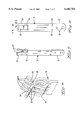
- FIG. 1 is a side view of the bus bar contact of the present invention
- FIG. 2 is a front view of the bus bar
- FIG. 3 is an isometric view of the bus bar
- FIG. 4 is an enlarged view of the contact fingers of the bus bar
- FIG. 5 is an isometric view of a third embodiment of the present invention.
- FIG. 6 is a front view of the bus bar FIG. 5;
- FIG. 7 is an isometric view of an alternative embodiment of the present invention.
- FIG. 8 is a side view of the bus bar contact of FIG. 7.
- FIGS. 1-4 show a first embodiment of the bus bar contact of the present invention.
- the bus bar contact 10 is used to provide electrical power in an electrical meter.
- the bus bar contact 10 has a tab contact portion 12 and a receptacle portion 14.
- the bus bar contact is a one piece contact.
- the receptacle portion and the blade portion of the contact 10 are all one integral piece.
- the bus bar contact 10 is formed from one piece of metal, such as a high strength copper alloy, for example CDA 151, wherein the receptacle portion 14 and the tab portion 12 is stamped and formed from a single piece of metal.
- the blade portion 12 is designed to be received in a mating receptacle connector to provide electrical connection thereto.
- the blade portion 12 has recesses 18 and protrusions 20. These recesses 18 and protrusions 20 serve to provide alignment and latching features to the mating receptacle connector for the blade portion 12. Other features may be included on the blade portion 12 to provide securing or aligning features as needed for a specific use of the contact 10.
- the receptacle portion 14 has a series of resilient fingers 22, 24.
- the resilient fingers 22, 24 are separated from each other thereby forming a slot 26 into which a mating blade contact is received to provide electrical connection.
- Adjacent resilient fingers 22, 24 are disposed along opposite sides of the slot 26.
- the resilient fingers 22, 24 each have protrusions 28 along a mating surface along the slot 26 to provide good electrical connection with the mating blade contact.
- the resilient fingers 22, 24 are stamped and formed from the integral piece which forms the bus bar contact 10.
- the resilient fingers 22, 24 are sheared from each other during the forming process so that there is no material removed from between the adjacent resilient fingers 22, 24 such that the side edges of successive ones of the fingers are coplanar with no gap therebetween as seen in FIG. 2, since no material was removed in the shearing process.
- the side edges of the body between the receptacle and blade portions are parallel. This provides for the same amount of material along the receptacle contact interface as is used for the rest of the blade contact 10, defining a constant conductive and blade portions.
- FIGS. 2-4 in this embodiment of the bus bar contact seven resilient fingers 22, 24 are provided to provide good electrical contact with the mating blade. Furthermore, as can be seen in FIG.
- resilient fingers 22 are slightly wider than the resilient fingers 24. This can be seen at A wherein the width of the resilient fingers 22 is shown and at B wherein the width of the resilient fingers 24 are shown. Because an odd number of resilient fingers are formed, the width of the resilient fingers on one side of the contact are made slightly wider than the width of the resilient fingers on the other side of the contact, thereby balancing the amount of material, and therefore the force, on the opposite sides of the mating blade connector. The combined total width of the resilient fingers 24 on one side of the mating slot 26 is equal to the combined total width of the resilient fingers 22 on the other side of the mating slot 26, thereby balancing the force on either side of the mating tab contact.
- the contact can have an even number of resilient fingers. If the resilient fingers are disposed in a similar alternating pattern along the slot, a bending force will be transmitted to the mating blade connector. This may be fine if the mating blade contact can tolerate the bending force. However, if the mating blade contact cannot tolerate the bending force, in order to avoid that bending force, the two center most resilient fingers may be disposed on the same side of the slot, and the resilient fingers are arranged in an alternating pattern extending from the center most fingers towards the outer portions of the contact. Since there is an equal number of resilient fingers on either side of the slot, the width of each of the resilient fingers would be the same, thereby providing an equal force on both sides of the mating blade connector.
- FIGS. 5-6 show an alternative embodiment of the bus bar contact 10 of the present invention.
- the bus bar contact shown in FIGS. 5 and 6 is essentially identical that shown in FIG. 1-6, however the bus bar contact shown in FIG. 5 has only 3 resilient fingers 22', 24'.
- the central resilient finger 22' is significantly wider than the outer resilient fingers 24'
- A' indicates the width of the resilient finger 22'
- B' represents the width of the resilient fingers 24'.
- the width of A' is equal to the combined widths of B' thereby providing an equal amount of force on opposite sides of the mating contact.
- FIGS. 7 and 8 show an alternative embodiment of the bus bar contact 10 of the present invention.
- the bus bar contact 10 has an even number of resilient fingers 22", 24" which are disposed in an alternating pattern across the mating interface.
- the bus bar contact 10 in FIGS. 7 and 8 have contact protrusions 30 disposed along the mating surface of the resilient fingers 22", 24".
- the contact protrusions 30 are stamped and formed during the forming process for the contact 10.
- the contact 10 shown in FIGS. 7 and 8 has a negative width mating slot 26".
- the resilient fingers 22", 24" are arranged so that their mating surfaces extend beyond each other along the mating slot 26", thereby requiring that the resilient fingers 22", 24" must be deflected during the insertion of even the smallest mating blade contact.
- the bus bar contact 10 of the different embodiments are made by shearing and forming the resilient fingers. These fingers make contact across the width of the mating blade at multiple locations, in which they act as parallel circuit paths. It is known from past experience that connectors with multiple contact locations have better electrical performance than designs which have only one. By connecting to the mating blade at multiple locations across the width, and alternating the face of the blade that adjacent contact fingers make contact to, the constriction resistance at the separable contact interface is minimized.
- An advantage of disclosed embodiments of the present invention is that the fingers are made by shearing without removal of metal therebetween. This results in several benefits. Firstly, because there is no material removed, the current flux path through the fingers at the root of the beam is undisturbed, and the constriction resistance is virtually eliminated. Secondly, by utilizing the full geometry of the contact beams with this configuration, the bulk resistance per unit length of the beam through the finger area is the same as other locations along the bus bar contact which minimizes the bulk resistance. Finally, the bus bar contact is easy to manufacture and no slivers or scrap has to be removed from between the fingers.
- Width of the beams on the odd and even number sides are slightly different to give equal deflection of the beam upon mating of the power meter blade.
- bus bar contacts of the present invention and many of their attendant advantages will be understood from the foregoing description. It is apparent that many changes may be made in the form, construction, an arrangement of parts thereof without departing from the spirit or scope of the invention, or sacrificing all of their material advantages.
Abstract
Description
Claims (5)
Priority Applications (1)
| Application Number | Priority Date | Filing Date | Title |
|---|---|---|---|
| US08/828,871 US6102754A (en) | 1997-03-31 | 1997-03-31 | Bus bar contact |
Applications Claiming Priority (1)
| Application Number | Priority Date | Filing Date | Title |
|---|---|---|---|
| US08/828,871 US6102754A (en) | 1997-03-31 | 1997-03-31 | Bus bar contact |
Publications (1)
| Publication Number | Publication Date |
|---|---|
| US6102754A true US6102754A (en) | 2000-08-15 |
Family
ID=25252975
Family Applications (1)
| Application Number | Title | Priority Date | Filing Date |
|---|---|---|---|
| US08/828,871 Expired - Lifetime US6102754A (en) | 1997-03-31 | 1997-03-31 | Bus bar contact |
Country Status (1)
| Country | Link |
|---|---|
| US (1) | US6102754A (en) |
Cited By (40)
| Publication number | Priority date | Publication date | Assignee | Title |
|---|---|---|---|---|
| US6383039B1 (en) * | 2000-12-30 | 2002-05-07 | Hon Hai Precision Ind. Co., Ltd. | Electrical connector |
| US20020193019A1 (en) * | 2001-06-14 | 2002-12-19 | Blanchfield Michael Allen | Multi-beam power contact for an electrical connector |
| US20040259432A1 (en) * | 2001-04-05 | 2004-12-23 | Stephen Andersen | Four-sided electrical contact and method of making same |
| US20050221690A1 (en) * | 2004-04-05 | 2005-10-06 | Yamaichi Electronics Co., Ltd. | Female side connector for high current |
| US20060030178A1 (en) * | 2004-08-05 | 2006-02-09 | Ddk Ltd. And Hitachi, Ltd. | Electrical connector |
| US20060140879A1 (en) * | 2004-12-28 | 2006-06-29 | Linh Fruge | Two phase toothpaste composition |
| US20060140882A1 (en) * | 2004-12-29 | 2006-06-29 | Tambs Gary E | Two phase whitening oral care composition |
| US20060160380A1 (en) * | 2005-01-20 | 2006-07-20 | Hon Hai Precision Ind. Co., Ltd. | Mating extender for electrically connecting with two electrical connectors |
| US20060205283A1 (en) * | 2005-03-09 | 2006-09-14 | Erni Elektroapparate Gmbh | Spring bushing for miniature plug-in connectors |
| US20070212952A1 (en) * | 2006-03-09 | 2007-09-13 | Plastab I Anderstorp Ab | Contact finger with transverse depression, matchable in the depression on a corresponding contact finger |
| US20070212951A1 (en) * | 2006-03-09 | 2007-09-13 | Plastab I Anderstorp Ab | Contact finger with grooves |
| US20070264882A1 (en) * | 2006-05-10 | 2007-11-15 | K.S. Terminals Inc. | Battery terminal connector and conductive elements thereof |
| EP1901398A1 (en) * | 2006-09-14 | 2008-03-19 | Hager Electro GmbH & Co. KG | Connector piece for creating an electric contact |
| CN100452555C (en) * | 2006-03-15 | 2009-01-14 | 健和兴端子股份有限公司 | Battery terminal connector and its conducting element |
| JP2009081144A (en) * | 2002-05-23 | 2009-04-16 | Fci | Power connector |
| USD608293S1 (en) | 2009-01-16 | 2010-01-19 | Fci Americas Technology, Inc. | Vertical electrical connector |
| USD610548S1 (en) | 2009-01-16 | 2010-02-23 | Fci Americas Technology, Inc. | Right-angle electrical connector |
| US20100190360A1 (en) * | 2009-01-26 | 2010-07-29 | Lear Corporation | Fuse box and method of making a fuse box |
| USD640637S1 (en) | 2009-01-16 | 2011-06-28 | Fci Americas Technology Llc | Vertical electrical connector |
| USD641709S1 (en) | 2009-01-16 | 2011-07-19 | Fci Americas Technology Llc | Vertical electrical connector |
| US20120083171A1 (en) * | 2009-08-17 | 2012-04-05 | Byrne Norman R | Solid wire terminal |
| JP2012119208A (en) * | 2010-12-02 | 2012-06-21 | Japan Aviation Electronics Industry Ltd | Connector |
| USD664096S1 (en) | 2009-01-16 | 2012-07-24 | Fci Americas Technology Llc | Vertical electrical connector |
| US20130217267A1 (en) * | 2012-02-21 | 2013-08-22 | Rongzhe Guo | Connector assembly capable of sustaining large current |
| US20140235115A1 (en) * | 2013-02-15 | 2014-08-21 | Tyco Electronics Amp Gmbh | Electrical Connector |
| US20150118878A1 (en) * | 2013-10-24 | 2015-04-30 | Asco Power Technologies, L.P. | Bus Connector with Reduced Insertion Force |
| US9070990B2 (en) | 2013-05-21 | 2015-06-30 | Tyco Electronics Corporation | Power connector having opposing contact springs |
| US20160087366A1 (en) * | 2014-09-22 | 2016-03-24 | Ideal Industries, Inc. | Terminals for electrical connectors |
| EP3188287A1 (en) * | 2015-12-30 | 2017-07-05 | Thunder Power New Energy Vehicle Development Company Limited | Integrated busbar and battery connection for electric vehicle battery packs |
| US9711921B2 (en) | 2015-02-27 | 2017-07-18 | Norman R. Byrne | Electrical contact receptacle for bus bars and blade terminals |
| CN107068953A (en) * | 2015-12-30 | 2017-08-18 | 昶洧新能源汽车发展有限公司 | Integrated bus bars and battery for electric vehicle battery group are connected |
| US10079130B2 (en) * | 2016-05-23 | 2018-09-18 | Lsis Co., Ltd. | Circuit breaker |
| US20190148866A1 (en) * | 2016-05-02 | 2019-05-16 | Valeo Systèmes d'Essuyage | Contact element for producing an electric connection with a counterpart element, the electric connection, and windscreen wiper motor |
| EP3240382B1 (en) * | 2016-04-14 | 2020-02-12 | TE Connectivity Industrial GmbH | Electrical linking module for a pneumatic valve system, control unit for a pneumatic valve system |
| US10608356B2 (en) | 2018-08-30 | 2020-03-31 | L-3 Technologies, Inc. | Multiple node bus bar contacts for high-power electronic assemblies |
| EP3240381B1 (en) * | 2016-04-14 | 2020-04-01 | TE Connectivity Industrial GmbH | Electrical linking module for a pneumatic valve system, control unit for a pneumatic valve system and method for mounting an electric linking module |
| EP3240383B1 (en) * | 2016-04-14 | 2020-07-08 | TE Connectivity Industrial GmbH | Electrical linking module for a pneumatic valve system, control unit for a pneumatic valve system |
| US10826215B2 (en) * | 2018-09-25 | 2020-11-03 | Alltop Electronics (Suzhou) Ltd. | Electrical connector and electrical connector assembly with the same |
| US20210328376A1 (en) * | 2020-04-20 | 2021-10-21 | Tyco Electronics (Shanghai) Co. Ltd. | Connector |
| US11605914B2 (en) * | 2020-05-05 | 2023-03-14 | Te Connectivity Solutions Gmbh | Electrical contact with multiple contact points having equivalent normal force |
Citations (16)
| Publication number | Priority date | Publication date | Assignee | Title |
|---|---|---|---|---|
| US3865462A (en) * | 1973-03-07 | 1975-02-11 | Amp Inc | Preloaded contact and latchable housing assembly |
| US4037915A (en) * | 1976-04-29 | 1977-07-26 | Comatel - Comptoir Europeen De Materiel Electronique | Electrical connector strips |
| US4257668A (en) * | 1979-01-02 | 1981-03-24 | Gte Automatic Electric Laboratories, Inc. | Edge clip terminal for mounting thick film hybrid circuits in printed circuit boards |
| US4384754A (en) * | 1980-11-17 | 1983-05-24 | Amp Incorporated | Multi-plane connectors |
| US4684191A (en) * | 1986-06-30 | 1987-08-04 | Amp Incorporated | Electrical terminal and electrical connector assembly |
| US4717361A (en) * | 1985-08-02 | 1988-01-05 | Daiichi Denshi Kogyo Kabushiki Kaisha | Contact for connector |
| US4740180A (en) * | 1987-03-16 | 1988-04-26 | Molex Incorporated | Low insertion force mating electrical contact |
| US4820182A (en) * | 1987-12-18 | 1989-04-11 | Molex Incorporated | Hermaphroditic L. I. F. mating electrical contacts |
| US4869673A (en) * | 1987-12-02 | 1989-09-26 | Amp Incorporated | Circuit panel assembly with elevated power buses |
| US4887976A (en) * | 1988-08-18 | 1989-12-19 | Amp Incorporated | Electrical terminals for flat power cable |
| US4892485A (en) * | 1988-06-16 | 1990-01-09 | Patton Victor L | Adapter plate for converting a three phase meter socket for use with a single phase watt hour meter |
| US4944691A (en) * | 1988-08-15 | 1990-07-31 | Cooper Industries, Inc. | Holder for a removable circuit element |
| US4944692A (en) * | 1989-02-24 | 1990-07-31 | Allina Edward F | Electrical plug-in connectors |
| US5024610A (en) * | 1989-08-16 | 1991-06-18 | Amp Incorporated | Low profile spring contact with protective guard means |
| US5129841A (en) * | 1991-08-23 | 1992-07-14 | Allina Edward F | Plug-and-jack electrical connector |
| US5334057A (en) * | 1993-02-19 | 1994-08-02 | Blackwell Larry R | Connectors for electrical meter socket adapters |
-
1997
- 1997-03-31 US US08/828,871 patent/US6102754A/en not_active Expired - Lifetime
Patent Citations (16)
| Publication number | Priority date | Publication date | Assignee | Title |
|---|---|---|---|---|
| US3865462A (en) * | 1973-03-07 | 1975-02-11 | Amp Inc | Preloaded contact and latchable housing assembly |
| US4037915A (en) * | 1976-04-29 | 1977-07-26 | Comatel - Comptoir Europeen De Materiel Electronique | Electrical connector strips |
| US4257668A (en) * | 1979-01-02 | 1981-03-24 | Gte Automatic Electric Laboratories, Inc. | Edge clip terminal for mounting thick film hybrid circuits in printed circuit boards |
| US4384754A (en) * | 1980-11-17 | 1983-05-24 | Amp Incorporated | Multi-plane connectors |
| US4717361A (en) * | 1985-08-02 | 1988-01-05 | Daiichi Denshi Kogyo Kabushiki Kaisha | Contact for connector |
| US4684191A (en) * | 1986-06-30 | 1987-08-04 | Amp Incorporated | Electrical terminal and electrical connector assembly |
| US4740180A (en) * | 1987-03-16 | 1988-04-26 | Molex Incorporated | Low insertion force mating electrical contact |
| US4869673A (en) * | 1987-12-02 | 1989-09-26 | Amp Incorporated | Circuit panel assembly with elevated power buses |
| US4820182A (en) * | 1987-12-18 | 1989-04-11 | Molex Incorporated | Hermaphroditic L. I. F. mating electrical contacts |
| US4892485A (en) * | 1988-06-16 | 1990-01-09 | Patton Victor L | Adapter plate for converting a three phase meter socket for use with a single phase watt hour meter |
| US4944691A (en) * | 1988-08-15 | 1990-07-31 | Cooper Industries, Inc. | Holder for a removable circuit element |
| US4887976A (en) * | 1988-08-18 | 1989-12-19 | Amp Incorporated | Electrical terminals for flat power cable |
| US4944692A (en) * | 1989-02-24 | 1990-07-31 | Allina Edward F | Electrical plug-in connectors |
| US5024610A (en) * | 1989-08-16 | 1991-06-18 | Amp Incorporated | Low profile spring contact with protective guard means |
| US5129841A (en) * | 1991-08-23 | 1992-07-14 | Allina Edward F | Plug-and-jack electrical connector |
| US5334057A (en) * | 1993-02-19 | 1994-08-02 | Blackwell Larry R | Connectors for electrical meter socket adapters |
Cited By (69)
| Publication number | Priority date | Publication date | Assignee | Title |
|---|---|---|---|---|
| US6383039B1 (en) * | 2000-12-30 | 2002-05-07 | Hon Hai Precision Ind. Co., Ltd. | Electrical connector |
| US7021977B2 (en) * | 2001-04-05 | 2006-04-04 | Stephen Andersen | Four-sided electrical contact |
| US20040259432A1 (en) * | 2001-04-05 | 2004-12-23 | Stephen Andersen | Four-sided electrical contact and method of making same |
| US6776635B2 (en) * | 2001-06-14 | 2004-08-17 | Tyco Electronics Corporation | Multi-beam power contact for an electrical connector |
| US20020193019A1 (en) * | 2001-06-14 | 2002-12-19 | Blanchfield Michael Allen | Multi-beam power contact for an electrical connector |
| JP2009081144A (en) * | 2002-05-23 | 2009-04-16 | Fci | Power connector |
| US20050221690A1 (en) * | 2004-04-05 | 2005-10-06 | Yamaichi Electronics Co., Ltd. | Female side connector for high current |
| US7168990B2 (en) * | 2004-04-05 | 2007-01-30 | Yamaichi Electronics Co., Ltd. | Female side connector for high current |
| US20060030178A1 (en) * | 2004-08-05 | 2006-02-09 | Ddk Ltd. And Hitachi, Ltd. | Electrical connector |
| US7083433B2 (en) * | 2004-08-05 | 2006-08-01 | Ddk Ltd. | Electrical connector |
| US20060140879A1 (en) * | 2004-12-28 | 2006-06-29 | Linh Fruge | Two phase toothpaste composition |
| US20060140882A1 (en) * | 2004-12-29 | 2006-06-29 | Tambs Gary E | Two phase whitening oral care composition |
| US20060160380A1 (en) * | 2005-01-20 | 2006-07-20 | Hon Hai Precision Ind. Co., Ltd. | Mating extender for electrically connecting with two electrical connectors |
| US7104808B2 (en) | 2005-01-20 | 2006-09-12 | Hon Hai Precision Ind. Co., Ltd. | Mating extender for electrically connecting with two electrical connectors |
| US20060205283A1 (en) * | 2005-03-09 | 2006-09-14 | Erni Elektroapparate Gmbh | Spring bushing for miniature plug-in connectors |
| JP2006253142A (en) * | 2005-03-09 | 2006-09-21 | Erni Elektroapparate Gmbh | Spring socket for plug connector |
| US7303449B2 (en) | 2005-03-09 | 2007-12-04 | Erni Electronics Gmbh | Spring bushing for miniature plug-in connectors having contact spring with insertion depth equal to or less than insertion width |
| DE102005010704A1 (en) * | 2005-03-09 | 2006-09-21 | Erni Elektroapparate Gmbh | Spring bushing for miniature connectors |
| DE102005010704B4 (en) * | 2005-03-09 | 2011-05-12 | Erni Electronics Gmbh | Spring bushing for miniature connectors |
| US20070212952A1 (en) * | 2006-03-09 | 2007-09-13 | Plastab I Anderstorp Ab | Contact finger with transverse depression, matchable in the depression on a corresponding contact finger |
| US20070212951A1 (en) * | 2006-03-09 | 2007-09-13 | Plastab I Anderstorp Ab | Contact finger with grooves |
| US7494359B2 (en) * | 2006-03-09 | 2009-02-24 | Plastab I Anderstorp | Contact finger with transverse depression, matchable in the depression on a corresponding contact finger |
| US7530862B2 (en) * | 2006-03-09 | 2009-05-12 | Plastab; Anderstorp Ab | Contact finger with grooves |
| CN100452555C (en) * | 2006-03-15 | 2009-01-14 | 健和兴端子股份有限公司 | Battery terminal connector and its conducting element |
| US20070264882A1 (en) * | 2006-05-10 | 2007-11-15 | K.S. Terminals Inc. | Battery terminal connector and conductive elements thereof |
| EP1901398A1 (en) * | 2006-09-14 | 2008-03-19 | Hager Electro GmbH & Co. KG | Connector piece for creating an electric contact |
| USD651981S1 (en) | 2009-01-16 | 2012-01-10 | Fci Americas Technology Llc | Vertical electrical connector |
| USD696199S1 (en) | 2009-01-16 | 2013-12-24 | Fci Americas Technology Llc | Vertical electrical connector |
| USD610548S1 (en) | 2009-01-16 | 2010-02-23 | Fci Americas Technology, Inc. | Right-angle electrical connector |
| USD640637S1 (en) | 2009-01-16 | 2011-06-28 | Fci Americas Technology Llc | Vertical electrical connector |
| USD641709S1 (en) | 2009-01-16 | 2011-07-19 | Fci Americas Technology Llc | Vertical electrical connector |
| USD647058S1 (en) | 2009-01-16 | 2011-10-18 | Fci Americas Technology Llc | Vertical electrical connector |
| USD608293S1 (en) | 2009-01-16 | 2010-01-19 | Fci Americas Technology, Inc. | Vertical electrical connector |
| USD660245S1 (en) | 2009-01-16 | 2012-05-22 | Fci Americas Technology Llc | Vertical electrical connector |
| USD664096S1 (en) | 2009-01-16 | 2012-07-24 | Fci Americas Technology Llc | Vertical electrical connector |
| DE102009006134A1 (en) | 2009-01-26 | 2010-08-05 | Lear Corp., Southfield | Fuse box and method of making a fuse box |
| US7850463B2 (en) | 2009-01-26 | 2010-12-14 | Lear Corporation | Fuse box and method of making a fuse box |
| US20100190360A1 (en) * | 2009-01-26 | 2010-07-29 | Lear Corporation | Fuse box and method of making a fuse box |
| DE102009006134B4 (en) * | 2009-01-26 | 2017-12-07 | Lear Corp. | Fuse box and busbar for a fuse box |
| US20140113510A1 (en) * | 2009-08-17 | 2014-04-24 | Norman R. Byrne | Solid wire terminal |
| US8616926B2 (en) * | 2009-08-17 | 2013-12-31 | Norman R. Byrne | Solid wire terminal |
| US8920201B2 (en) * | 2009-08-17 | 2014-12-30 | Norman R. Byrne | Solid wire terminal |
| US20120083171A1 (en) * | 2009-08-17 | 2012-04-05 | Byrne Norman R | Solid wire terminal |
| JP2012119208A (en) * | 2010-12-02 | 2012-06-21 | Japan Aviation Electronics Industry Ltd | Connector |
| US20130217267A1 (en) * | 2012-02-21 | 2013-08-22 | Rongzhe Guo | Connector assembly capable of sustaining large current |
| US9379459B2 (en) * | 2013-02-15 | 2016-06-28 | Te Connectivity Germany Gmbh | Electrical connector |
| US20140235115A1 (en) * | 2013-02-15 | 2014-08-21 | Tyco Electronics Amp Gmbh | Electrical Connector |
| US9070990B2 (en) | 2013-05-21 | 2015-06-30 | Tyco Electronics Corporation | Power connector having opposing contact springs |
| US9172170B2 (en) * | 2013-10-24 | 2015-10-27 | Asco Power Technologies, L.P. | Bus connector with reduced insertion force |
| US20150118878A1 (en) * | 2013-10-24 | 2015-04-30 | Asco Power Technologies, L.P. | Bus Connector with Reduced Insertion Force |
| US20160087366A1 (en) * | 2014-09-22 | 2016-03-24 | Ideal Industries, Inc. | Terminals for electrical connectors |
| US9647368B2 (en) * | 2014-09-22 | 2017-05-09 | Ideal Industries, Inc. | Terminals for electrical connectors |
| US10014614B2 (en) | 2014-09-22 | 2018-07-03 | Ideal Industries, Inc. | Terminals for electrical connectors |
| US9711921B2 (en) | 2015-02-27 | 2017-07-18 | Norman R. Byrne | Electrical contact receptacle for bus bars and blade terminals |
| EP3188287A1 (en) * | 2015-12-30 | 2017-07-05 | Thunder Power New Energy Vehicle Development Company Limited | Integrated busbar and battery connection for electric vehicle battery packs |
| CN107068953A (en) * | 2015-12-30 | 2017-08-18 | 昶洧新能源汽车发展有限公司 | Integrated bus bars and battery for electric vehicle battery group are connected |
| US9966586B2 (en) | 2015-12-30 | 2018-05-08 | Thunder Power New Energy Vehicle Development Company Limited | Integrated busbar and battery connection for electric vehicle battery packs |
| EP3240382B1 (en) * | 2016-04-14 | 2020-02-12 | TE Connectivity Industrial GmbH | Electrical linking module for a pneumatic valve system, control unit for a pneumatic valve system |
| EP3240381B1 (en) * | 2016-04-14 | 2020-04-01 | TE Connectivity Industrial GmbH | Electrical linking module for a pneumatic valve system, control unit for a pneumatic valve system and method for mounting an electric linking module |
| EP3240383B1 (en) * | 2016-04-14 | 2020-07-08 | TE Connectivity Industrial GmbH | Electrical linking module for a pneumatic valve system, control unit for a pneumatic valve system |
| US20190148866A1 (en) * | 2016-05-02 | 2019-05-16 | Valeo Systèmes d'Essuyage | Contact element for producing an electric connection with a counterpart element, the electric connection, and windscreen wiper motor |
| US10686271B2 (en) * | 2016-05-02 | 2020-06-16 | Valeo Systèmes d'Essuyage | Contact element for producing an electric connection with a counterpart element, the electric connection, and windscreen wiper motor |
| US10079130B2 (en) * | 2016-05-23 | 2018-09-18 | Lsis Co., Ltd. | Circuit breaker |
| US10608356B2 (en) | 2018-08-30 | 2020-03-31 | L-3 Technologies, Inc. | Multiple node bus bar contacts for high-power electronic assemblies |
| US10826215B2 (en) * | 2018-09-25 | 2020-11-03 | Alltop Electronics (Suzhou) Ltd. | Electrical connector and electrical connector assembly with the same |
| US11139599B2 (en) * | 2018-09-25 | 2021-10-05 | Alltop Electronics (Suzhou) Ltd. | Electrical connector and electrical connector assembly with the same |
| US20210328376A1 (en) * | 2020-04-20 | 2021-10-21 | Tyco Electronics (Shanghai) Co. Ltd. | Connector |
| US11695230B2 (en) * | 2020-04-20 | 2023-07-04 | Tyco Electronics (Shanghai) Co., Ltd. | Connector including a terminal with a pair of sub-terminals |
| US11605914B2 (en) * | 2020-05-05 | 2023-03-14 | Te Connectivity Solutions Gmbh | Electrical contact with multiple contact points having equivalent normal force |
Similar Documents
| Publication | Publication Date | Title |
|---|---|---|
| US6102754A (en) | Bus bar contact | |
| US5681190A (en) | Torsional blade receptacle | |
| JP4589362B2 (en) | High speed, high density electrical connector | |
| US5692928A (en) | Electrical connector having terminals with improved retention means | |
| US4395086A (en) | Electrical contact for electrical connector assembly | |
| US4990110A (en) | Electrical contact arrangement | |
| EP0492815B1 (en) | Stamped and formed electrical tab | |
| US4772234A (en) | Terminal for establishing electrical contact with a post | |
| EP0726615A2 (en) | Electrical contact | |
| WO2005011065A1 (en) | Female terminal with sacrificial arc discharge contacts | |
| US6918798B2 (en) | Female terminal with flexible sidewalls and flat angled contacts | |
| EP0551085A1 (en) | Male ecletrical terminal with anti-overstress means | |
| EP0775374B1 (en) | Connector for an electrical cable | |
| EP0530964A2 (en) | Electrical connector having improved grounding bus bars | |
| US5890936A (en) | Electrical terminal | |
| US4331376A (en) | Electric connectors | |
| CN114465032A (en) | Electrical connector assembly | |
| EP1089387A2 (en) | A modular female electrical terminal | |
| EP0117021B1 (en) | Socket connector | |
| US20020055297A1 (en) | Modular female electrical terminal | |
| CN114336128B (en) | Terminal for connecting a plurality of terminals | |
| US6095839A (en) | Electrical connector | |
| US11024991B2 (en) | Receptacle terminal | |
| US10446944B1 (en) | Devices, systems, and methods for increasing terminal electrical contact | |
| EP1182680A1 (en) | Fuse and fuse-mounting electric connection box |
Legal Events
| Date | Code | Title | Description |
|---|---|---|---|
| AS | Assignment |
Owner name: WHITAKER CORPORATION, THE, DELAWARE Free format text: ASSIGNMENT OF ASSIGNORS INTEREST;ASSIGNORS:CAPPER, HARRY MILTON;JACOBEEN, BRIAN FRANK;ROBERTSON, JAMES WILLIAM;REEL/FRAME:008506/0540 Effective date: 19970327 |
|
| STCF | Information on status: patent grant |
Free format text: PATENTED CASE |
|
| FPAY | Fee payment |
Year of fee payment: 4 |
|
| FPAY | Fee payment |
Year of fee payment: 8 |
|
| REMI | Maintenance fee reminder mailed | ||
| FPAY | Fee payment |
Year of fee payment: 12 |
|
| AS | Assignment |
Owner name: TYCO ELECTRONICS SERVICES GMBH, SWITZERLAND Free format text: ASSIGNMENT OF ASSIGNORS INTEREST;ASSIGNOR:THE WHITAKER LLC;REEL/FRAME:040283/0940 Effective date: 20161001 |