US6125046A - Switching power supply having a high efficiency starting circuit - Google Patents
Switching power supply having a high efficiency starting circuit Download PDFInfo
- Publication number
- US6125046A US6125046A US09/435,290 US43529099A US6125046A US 6125046 A US6125046 A US 6125046A US 43529099 A US43529099 A US 43529099A US 6125046 A US6125046 A US 6125046A
- Authority
- US
- United States
- Prior art keywords
- voltage
- power supply
- feedback
- circuit
- coupled
- Prior art date
- Legal status (The legal status is an assumption and is not a legal conclusion. Google has not performed a legal analysis and makes no representation as to the accuracy of the status listed.)
- Expired - Lifetime
Links
Images


Classifications
-
- H—ELECTRICITY
- H02—GENERATION; CONVERSION OR DISTRIBUTION OF ELECTRIC POWER
- H02M—APPARATUS FOR CONVERSION BETWEEN AC AND AC, BETWEEN AC AND DC, OR BETWEEN DC AND DC, AND FOR USE WITH MAINS OR SIMILAR POWER SUPPLY SYSTEMS; CONVERSION OF DC OR AC INPUT POWER INTO SURGE OUTPUT POWER; CONTROL OR REGULATION THEREOF
- H02M1/00—Details of apparatus for conversion
- H02M1/36—Means for starting or stopping converters
-
- H—ELECTRICITY
- H02—GENERATION; CONVERSION OR DISTRIBUTION OF ELECTRIC POWER
- H02M—APPARATUS FOR CONVERSION BETWEEN AC AND AC, BETWEEN AC AND DC, OR BETWEEN DC AND DC, AND FOR USE WITH MAINS OR SIMILAR POWER SUPPLY SYSTEMS; CONVERSION OF DC OR AC INPUT POWER INTO SURGE OUTPUT POWER; CONTROL OR REGULATION THEREOF
- H02M3/00—Conversion of dc power input into dc power output
- H02M3/22—Conversion of dc power input into dc power output with intermediate conversion into ac
- H02M3/24—Conversion of dc power input into dc power output with intermediate conversion into ac by static converters
- H02M3/28—Conversion of dc power input into dc power output with intermediate conversion into ac by static converters using discharge tubes with control electrode or semiconductor devices with control electrode to produce the intermediate ac
- H02M3/325—Conversion of dc power input into dc power output with intermediate conversion into ac by static converters using discharge tubes with control electrode or semiconductor devices with control electrode to produce the intermediate ac using devices of a triode or a transistor type requiring continuous application of a control signal
- H02M3/335—Conversion of dc power input into dc power output with intermediate conversion into ac by static converters using discharge tubes with control electrode or semiconductor devices with control electrode to produce the intermediate ac using devices of a triode or a transistor type requiring continuous application of a control signal using semiconductor devices only
Definitions
- the invention relates generally to switching power supplies. More particularly, the invention relates to a switching power supply having a high efficiency starting circuit.
- a switching power supply provides a cost effective and energy efficient device for converting energy from a single direct current (DC) supply voltage into one or more DC output voltages that have a greater or lesser magnitude than the supply voltage.
- DC direct current
- a SPS has an integrated control circuit that modulates the duty cycle of a transistor switch, which controls the flow of energy into the primary of a transformer to produce one or more desired output voltages that are derived from the secondary of the transformer.
- the energy i.e., the time integral of power supplied to the primary of the transformer minus efficiency losses equals the energy transferred to the secondary of the transformer.
- control circuit increases the duty cycle of the transistor switch to provide more energy to the primary. Conversely, if less energy is needed by the secondary, then the control circuit decreases the duty cycle of the transistor switch.
- FIG. 1 is an exemplary schematic diagram of a conventional SPS, which includes a direct current (DC) voltage supply block 10, a voltage output block 20, a feedback block 30, and a switching control circuit 40.
- the DC voltage supply block 10 includes a bridge rectifier 1 and a filter capacitor C1.
- the bridge rectifier 1 rectifies alternating current (AC) line voltage to produce current pulses which are substantially smoothed to a DC supply voltage Vcc by the filter capacitor C1. For example, if the AC line voltage is 110 volts AC, then the smoothed DC supply voltage across capacitor C1 may be approximately 155 volts DC.
- the output voltage block 20 includes a switching transformer 22 having a primary winding L1 and secondary windings L2 and L3 and switching rectifier diodes D5 and D6 that receive current pulses from the respective secondary windings L2 and L2 to provide rectified current pulses to respective filter capacitors C2 and C3.
- the filter capacitors C2 and C3 smooth the rectified current pulses to substantially DC voltages.
- the feedback block 30 includes a voltage feedback amplifier 3 and a photo-coupler 4.
- the feedback amplifier 3 detects the DC voltage across the filter capacitor C2 and provides a proportional current to the photo-coupler 4.
- the switching control circuit 40 includes a pulse width modulated (PWM) signal generator 5, a switching transistor M1, and a feedback capacitor C4.
- PWM pulse width modulated
- the switching transistor M1 is connected to the primary L1 of the transformer 22 and is switched on and off by the PWM signal generator 5 at a duty cycle that is based on the magnitude of a feedback voltage VFB on the feedback capacitor C4.
- the supply voltage Vcc applied to the PWM signal generator 5 is substantially near zero volts DC and the PWM signal generator 5 is off. Additionally, because the PWM signal generator 5 is off, the switching transistor M1 is off, energy is not being provided to the primary winding L1, and the output voltages across capacitors C2 and C3 are substantially near zero volts DC.
- the start up resistor R is needed to the start the operation of the PWM signal generator 5, the start up resistor R becomes a significant source of energy inefficiency once the PWM signal generator 5 is operational. More specifically, a large voltage differential exists across the start up resistor R because the difference between the output voltage of the supply block 10 is substantially greater than the low voltage supply Vcc for the PWM signal generator 5.
- the output voltage of the supply block 10 may be 155 volts DC while the low voltage supply Vcc is 5 volts DC. This large voltage drop during continuous operation of the SPS results in a significant source of energy inefficiency.
- a high efficiency starting circuit for use in a switching power supply having a voltage source, a transformer, an output voltage circuit coupled to the transformer, a feedback circuit coupled to the output voltage circuit, and a pulse width modulated (PWM) signal generator coupled to the feedback circuit and the transformer, includes a transistor coupled to the voltage source, the feedback circuit, and the PWM signal generator.
- the transistor may be adapted to provide a source of current to the PWM signal generator during start up of the switching power supply and to conduct substantially near zero current once a feedback voltage from the feedback circuit reaches a predetermined voltage.
- a switching power supply includes a transformer and a power supply circuit that provides a supply voltage.
- the switching power supply may further include output voltage circuits coupled to the transformer, a voltage feedback circuit coupled to the output voltage circuits, a feedback capacitor coupled to the feedback circuit, and a switching control circuit.
- the switching control circuit may include a PWM signal generator having a feedback/supply input and a switching output signal, a first transistor coupled to the switching output signal and the primary winding, and a second transistor coupled to the supply voltage and the feedback capacitor.
- the second transistor may be adapted to supply current to the PWM signal generator and the feedback capacitor during start up of the switching power supply and may be further adapted to provide substantially near zero current to the PWM signal generator when a voltage on the feedback capacitor reaches a predetermined value.
- FIG. 1 is an exemplary schematic diagram of a conventional switching power supply
- FIG. 2 is an exemplary schematic diagram of a switching power supply having a high efficiency starting circuit
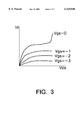
- FIG. 3 is a graphical representation illustrating the drain-source characteristics of a conventional junction field effect transistor.
- the switching control circuit 400 includes a PWM signal generator 303, a junction field effect transistor (JFET) 410, a metal oxide semiconductor field effect transistor (MOSFET) M10, a current sense resistor Rs, which protects the MOSFET M10 from overcurrent conditions, and may optionally include a compensation capacitor C500, which allows soft switching (i.e., prevents current overshooting) during start up of the PWM signal generator 303, all connected as shown.
- JFET junction field effect transistor
- MOSFET metal oxide semiconductor field effect transistor
- Rs current sense resistor
- the gate-source voltage Vgs is sufficiently negative to cause the JFET 410 to conduct substantially near zero current and the PWM signal generator 303 receives supply current/voltage via the feedback block 300.
- the JFET 410 is turned off once the SPS shown in FIG. 2 has started up and reached a normal operation condition, thereby eliminating the inefficiency that is normally associated with a resistive start up circuit, such as that shown in connection with the SPS of FIG. 1.
Abstract
Description
Claims (16)
Applications Claiming Priority (2)
| Application Number | Priority Date | Filing Date | Title |
|---|---|---|---|
| KR1019980047940A KR100293979B1 (en) | 1998-11-10 | 1998-11-10 | Switching Mode Power Supply |
| KR98-47940 | 1998-11-10 |
Publications (1)
| Publication Number | Publication Date |
|---|---|
| US6125046A true US6125046A (en) | 2000-09-26 |
Family
ID=19557672
Family Applications (1)
| Application Number | Title | Priority Date | Filing Date |
|---|---|---|---|
| US09/435,290 Expired - Lifetime US6125046A (en) | 1998-11-10 | 1999-11-05 | Switching power supply having a high efficiency starting circuit |
Country Status (2)
| Country | Link |
|---|---|
| US (1) | US6125046A (en) |
| KR (1) | KR100293979B1 (en) |
Cited By (82)
| Publication number | Priority date | Publication date | Assignee | Title |
|---|---|---|---|---|
| US6259618B1 (en) * | 2000-05-03 | 2001-07-10 | Analog And Power Electronics Corp. | Power chip set for a switching mode power supply having a device for providing a drive signal to a control unit upon startup |
| US6381151B1 (en) * | 1999-10-06 | 2002-04-30 | Fairfield Korea Semiconductor Ltd. | High efficiency switching controller |
| US6388900B1 (en) * | 2001-01-05 | 2002-05-14 | Phoenixtec Power Co., Ltd. | Constant-frequency active filter controlled by a peak current control mode |
| DE10108131A1 (en) * | 2001-02-21 | 2002-09-05 | Infineon Technologies Ag | Semiconductor circuit for power supply grid has a control circuit with a load which is switchable over time |
| WO2002071587A2 (en) * | 2001-03-06 | 2002-09-12 | Koninklijke Philips Electronics N.V. | Start-up circuit for switched mode power supply |
| US20030012043A1 (en) * | 2001-07-13 | 2003-01-16 | Delta Electronics, Inc. | Isolated switching power supply having volt-second clamping circuit |
| DE10132820A1 (en) * | 2001-07-06 | 2003-02-27 | Infineon Technologies Ag | Circuit device for switched regulator has control circuit, semiconductor switch and run-in circuit for application of operating voltage |
| US6597589B2 (en) * | 2001-12-14 | 2003-07-22 | Delta Electronics, Inc. | Power converter |
| US6646897B1 (en) * | 2002-04-30 | 2003-11-11 | ADC DCL Systems, Inc. | Method and system of slow output voltage ramp control for a power supply |
| US20040042239A1 (en) * | 2002-08-28 | 2004-03-04 | Saburou Kitano | Switching power supply apparatus |
| US20040070995A1 (en) * | 2002-10-09 | 2004-04-15 | Mitsubishi Denki Kabushiki Kaisha | DC-DC converter |
| US20040095106A1 (en) * | 2002-11-14 | 2004-05-20 | Fyre Storm, Inc. | Power converter circuitry and method |
| US6865094B2 (en) | 2002-05-14 | 2005-03-08 | International Business Machines Corporation | Circuit for AC adapter to reduce power drawn from an AC power source |
| US20050146903A1 (en) * | 2004-01-05 | 2005-07-07 | Ta-Yung Yang | Power-mode controlled power converter |
| US20050275443A1 (en) * | 2004-06-15 | 2005-12-15 | Shuey Kenneth C | Power supply restart delay prevention circuit |
| US20050285157A1 (en) * | 2004-06-23 | 2005-12-29 | Hower Philip L | Distributed high voltage JFET |
| US20070236970A1 (en) * | 2006-04-11 | 2007-10-11 | Ta-Yung Yang | High voltage start up circuit for power converters |
| US20070236274A1 (en) * | 2006-04-07 | 2007-10-11 | Chih-Feng Huang | Switch circuit to control on/off of a high voltage source |
| US20090189579A1 (en) * | 2008-01-30 | 2009-07-30 | Melanson John L | Switch state controller with a sense current generated operating voltage |
| US20100060202A1 (en) * | 2007-03-12 | 2010-03-11 | Melanson John L | Lighting System with Lighting Dimmer Output Mapping |
| US20100079125A1 (en) * | 2008-07-25 | 2010-04-01 | Melanson John L | Current sensing in a switching power converter |
| US20100171442A1 (en) * | 2008-12-12 | 2010-07-08 | Draper William A | Light Emitting Diode Based Lighting System With Time Division Ambient Light Feedback Response |
| US20100244726A1 (en) * | 2008-12-07 | 2010-09-30 | Melanson John L | Primary-side based control of secondary-side current for a transformer |
| US20100253305A1 (en) * | 2007-03-12 | 2010-10-07 | Melanson John L | Switching power converter control with spread spectrum based electromagnetic interference reduction |
| US20100271850A1 (en) * | 2009-04-27 | 2010-10-28 | Richtek Technology Corp. | Power transistor chip with built-in enhancement mode metal oxide semiconductor field effect transistor and application circuit thereof |
| US20100277072A1 (en) * | 2009-04-30 | 2010-11-04 | Draper William A | Calibration Of Lamps |
| CN101887076A (en) * | 2010-06-22 | 2010-11-17 | 深圳和而泰智能控制股份有限公司 | Circuit and device of isolation sensor |
| US20100308742A1 (en) * | 2007-03-12 | 2010-12-09 | Melanson John L | Power Control System for Current Regulated Light Sources |
| US20100321964A1 (en) * | 2009-06-17 | 2010-12-23 | Antony Brinlee | Power Adapter Employing a Power Reducer |
| US20100327765A1 (en) * | 2009-06-30 | 2010-12-30 | Melanson John L | Low energy transfer mode for auxiliary power supply operation in a cascaded switching power converter |
| US20110018590A1 (en) * | 2009-07-21 | 2011-01-27 | Richtek Technology Corp. | Feedback circuit and control method for an isolated power converter |
| CN101997534A (en) * | 2009-08-13 | 2011-03-30 | 立锜科技股份有限公司 | Feedback circuit and control method for isolated power converter |
| US20110074302A1 (en) * | 2009-09-30 | 2011-03-31 | Draper William A | Phase Control Dimming Compatible Lighting Systems |
| US20110110000A1 (en) * | 2009-11-09 | 2011-05-12 | Etter Brett E | Power System Having Voltage-Based Monitoring for Over Current Protection |
| US8040703B2 (en) | 2007-05-02 | 2011-10-18 | Cirrus Logic, Inc. | Power factor correction controller with feedback reduction |
| US8076920B1 (en) | 2007-03-12 | 2011-12-13 | Cirrus Logic, Inc. | Switching power converter and control system |
| CN102290971A (en) * | 2010-08-30 | 2011-12-21 | 科域半导体有限公司 | Switching converter |
| US8198874B2 (en) | 2009-06-30 | 2012-06-12 | Cirrus Logic, Inc. | Switching power converter with current sensing transformer auxiliary power supply |
| US8212491B2 (en) | 2008-07-25 | 2012-07-03 | Cirrus Logic, Inc. | Switching power converter control with triac-based leading edge dimmer compatibility |
| US8222872B1 (en) | 2008-09-30 | 2012-07-17 | Cirrus Logic, Inc. | Switching power converter with selectable mode auxiliary power supply |
| US8248145B2 (en) | 2009-06-30 | 2012-08-21 | Cirrus Logic, Inc. | Cascode configured switching using at least one low breakdown voltage internal, integrated circuit switch to control at least one high breakdown voltage external switch |
| US8279628B2 (en) | 2008-07-25 | 2012-10-02 | Cirrus Logic, Inc. | Audible noise suppression in a resonant switching power converter |
| US8299722B2 (en) | 2008-12-12 | 2012-10-30 | Cirrus Logic, Inc. | Time division light output sensing and brightness adjustment for different spectra of light emitting diodes |
| US20130051085A1 (en) * | 2011-08-24 | 2013-02-28 | Richtek Technology Corp. | Power supply, controller thereof and control method thereof |
| CN103117649A (en) * | 2011-11-16 | 2013-05-22 | 深圳市明微电子股份有限公司 | Method and device of starting circuit control with zero power consumption |
| US8488355B2 (en) | 2008-11-14 | 2013-07-16 | Power Systems Technologies, Ltd. | Driver for a synchronous rectifier and power converter employing the same |
| US8502520B2 (en) | 2007-03-14 | 2013-08-06 | Flextronics International Usa, Inc | Isolated power converter |
| US8514593B2 (en) | 2009-06-17 | 2013-08-20 | Power Systems Technologies, Ltd. | Power converter employing a variable switching frequency and a magnetic device with a non-uniform gap |
| CN103259431A (en) * | 2012-02-18 | 2013-08-21 | 立锜科技股份有限公司 | Isolated power converter circuit and control method thereof |
| US8520420B2 (en) | 2009-12-18 | 2013-08-27 | Power Systems Technologies, Ltd. | Controller for modifying dead time between switches in a power converter |
| US8520414B2 (en) | 2009-01-19 | 2013-08-27 | Power Systems Technologies, Ltd. | Controller for a power converter |
| US8536799B1 (en) | 2010-07-30 | 2013-09-17 | Cirrus Logic, Inc. | Dimmer detection |
| TWI411203B (en) * | 2008-04-11 | 2013-10-01 | System General Corp | Switching control circuit |
| US8569972B2 (en) | 2010-08-17 | 2013-10-29 | Cirrus Logic, Inc. | Dimmer output emulation |
| US8638578B2 (en) | 2009-08-14 | 2014-01-28 | Power System Technologies, Ltd. | Power converter including a charge pump employable in a power adapter |
| CN103595224A (en) * | 2009-08-13 | 2014-02-19 | 立锜科技股份有限公司 | Feedback circuit and control method for isolated power converter |
| US8767418B2 (en) | 2010-03-17 | 2014-07-01 | Power Systems Technologies Ltd. | Control system for a power converter and method of operating the same |
| US8787043B2 (en) | 2010-01-22 | 2014-07-22 | Power Systems Technologies, Ltd. | Controller for a power converter and method of operating the same |
| US8792256B2 (en) | 2012-01-27 | 2014-07-29 | Power Systems Technologies Ltd. | Controller for a switch and method of operating the same |
| US8792257B2 (en) | 2011-03-25 | 2014-07-29 | Power Systems Technologies, Ltd. | Power converter with reduced power dissipation |
| US20140268925A1 (en) * | 2013-03-15 | 2014-09-18 | Fairchild Korea Semiconductor Ltd. | Switch control circuit, switch control method and power supply device using the same |
| TWI453564B (en) * | 2009-07-21 | 2014-09-21 | Richtek Technology Corp | Feedback circuit and control method of an isolated power converter |
| US8963535B1 (en) | 2009-06-30 | 2015-02-24 | Cirrus Logic, Inc. | Switch controlled current sensing using a hall effect sensor |
| US8976549B2 (en) | 2009-12-03 | 2015-03-10 | Power Systems Technologies, Ltd. | Startup circuit including first and second Schmitt triggers and power converter employing the same |
| US9019061B2 (en) | 2009-03-31 | 2015-04-28 | Power Systems Technologies, Ltd. | Magnetic device formed with U-shaped core pieces and power converter employing the same |
| US9048747B2 (en) | 2011-11-23 | 2015-06-02 | Zahid Ansari | Switched-mode power supply startup circuit, method, and system incorporating same |
| US9077248B2 (en) | 2009-06-17 | 2015-07-07 | Power Systems Technologies Ltd | Start-up circuit for a power adapter |
| US9088216B2 (en) | 2009-01-19 | 2015-07-21 | Power Systems Technologies, Ltd. | Controller for a synchronous rectifier switch |
| US9099232B2 (en) | 2012-07-16 | 2015-08-04 | Power Systems Technologies Ltd. | Magnetic device and power converter employing the same |
| US9106130B2 (en) | 2012-07-16 | 2015-08-11 | Power Systems Technologies, Inc. | Magnetic device and power converter employing the same |
| US9161401B1 (en) | 2014-03-20 | 2015-10-13 | Cirrus Logic, Inc. | LED (light-emitting diode) string derived controller power supply |
| US9178415B1 (en) | 2009-10-15 | 2015-11-03 | Cirrus Logic, Inc. | Inductor over-current protection using a volt-second value representing an input voltage to a switching power converter |
| US9190898B2 (en) | 2012-07-06 | 2015-11-17 | Power Systems Technologies, Ltd | Controller for a power converter and method of operating the same |
| US9197132B2 (en) | 2006-12-01 | 2015-11-24 | Flextronics International Usa, Inc. | Power converter with an adaptive controller and method of operating the same |
| US9214264B2 (en) | 2012-07-16 | 2015-12-15 | Power Systems Technologies, Ltd. | Magnetic device and power converter employing the same |
| US9240712B2 (en) | 2012-12-13 | 2016-01-19 | Power Systems Technologies Ltd. | Controller including a common current-sense device for power switches of a power converter |
| US9246391B2 (en) | 2010-01-22 | 2016-01-26 | Power Systems Technologies Ltd. | Controller for providing a corrected signal to a sensed peak current through a circuit element of a power converter |
| US9300206B2 (en) | 2013-11-15 | 2016-03-29 | Power Systems Technologies Ltd. | Method for estimating power of a power converter |
| US9379629B2 (en) | 2012-07-16 | 2016-06-28 | Power Systems Technologies, Ltd. | Magnetic device and power converter employing the same |
| US9484832B2 (en) | 2011-12-14 | 2016-11-01 | Koninklijke Philips N.V. | Isolation of secondary transformer winding current during auxiliary power supply generation |
| US10263532B2 (en) | 2010-07-30 | 2019-04-16 | Signify Holding B.V. | Multiple power sources for a switching power converter controller |
| CN114884368A (en) * | 2022-05-23 | 2022-08-09 | 广州市因博电子科技有限公司 | Switching power supply circuit based on high-voltage input |
Families Citing this family (2)
| Publication number | Priority date | Publication date | Assignee | Title |
|---|---|---|---|---|
| KR20030064264A (en) * | 2002-12-03 | 2003-07-31 | 윤성환 | A waste water disposal system |
| KR101027063B1 (en) * | 2009-04-07 | 2011-04-11 | 수상개발(주) | Electrolytic sterilizer generator using constant current |
Citations (7)
| Publication number | Priority date | Publication date | Assignee | Title |
|---|---|---|---|---|
| US4236198A (en) * | 1977-12-16 | 1980-11-25 | Sony Corporation | Switching regulator |
| US4263645A (en) * | 1979-04-30 | 1981-04-21 | Gte Automatic Electric Laboratories, Inc. | Self-starting carrier subscriber power supply |
| US5014178A (en) * | 1990-05-14 | 1991-05-07 | Power Integrations, Inc. | Self powering technique for integrated switched mode power supply |
| US5285369A (en) * | 1992-09-01 | 1994-02-08 | Power Integrations, Inc. | Switched mode power supply integrated circuit with start-up self-biasing |
| US5436820A (en) * | 1993-06-09 | 1995-07-25 | Eldec Corporation | Power converter with dual PWM control |
| US5459652A (en) * | 1994-01-28 | 1995-10-17 | Compaq Computer Corp. | Boot strap circuit for power up control of power supplies |
| US6002598A (en) * | 1997-04-25 | 1999-12-14 | U.S. Philips Corporation | Switched-mode power supply having an improved start-up circuit |
-
1998
- 1998-11-10 KR KR1019980047940A patent/KR100293979B1/en not_active IP Right Cessation
-
1999
- 1999-11-05 US US09/435,290 patent/US6125046A/en not_active Expired - Lifetime
Patent Citations (7)
| Publication number | Priority date | Publication date | Assignee | Title |
|---|---|---|---|---|
| US4236198A (en) * | 1977-12-16 | 1980-11-25 | Sony Corporation | Switching regulator |
| US4263645A (en) * | 1979-04-30 | 1981-04-21 | Gte Automatic Electric Laboratories, Inc. | Self-starting carrier subscriber power supply |
| US5014178A (en) * | 1990-05-14 | 1991-05-07 | Power Integrations, Inc. | Self powering technique for integrated switched mode power supply |
| US5285369A (en) * | 1992-09-01 | 1994-02-08 | Power Integrations, Inc. | Switched mode power supply integrated circuit with start-up self-biasing |
| US5436820A (en) * | 1993-06-09 | 1995-07-25 | Eldec Corporation | Power converter with dual PWM control |
| US5459652A (en) * | 1994-01-28 | 1995-10-17 | Compaq Computer Corp. | Boot strap circuit for power up control of power supplies |
| US6002598A (en) * | 1997-04-25 | 1999-12-14 | U.S. Philips Corporation | Switched-mode power supply having an improved start-up circuit |
Cited By (130)
| Publication number | Priority date | Publication date | Assignee | Title |
|---|---|---|---|---|
| US6381151B1 (en) * | 1999-10-06 | 2002-04-30 | Fairfield Korea Semiconductor Ltd. | High efficiency switching controller |
| US20030117825A1 (en) * | 2000-05-03 | 2003-06-26 | Chorng-Wei Liaw | Power chip set for a switching mode power supply having a device for providing a drive signal to a control unit upon startup |
| US6888203B2 (en) | 2000-05-03 | 2005-05-03 | Analog And Power Electrics Corp. | Power chip set for a switching mode power supply having a device for providing a drive signal to a control unit upon startup |
| US6259618B1 (en) * | 2000-05-03 | 2001-07-10 | Analog And Power Electronics Corp. | Power chip set for a switching mode power supply having a device for providing a drive signal to a control unit upon startup |
| US6388900B1 (en) * | 2001-01-05 | 2002-05-14 | Phoenixtec Power Co., Ltd. | Constant-frequency active filter controlled by a peak current control mode |
| DE10108131A1 (en) * | 2001-02-21 | 2002-09-05 | Infineon Technologies Ag | Semiconductor circuit for power supply grid has a control circuit with a load which is switchable over time |
| US6577509B2 (en) | 2001-02-21 | 2003-06-10 | Infineon Technologies Ag | Semiconductor circuit and switch-mode power supply |
| WO2002071587A3 (en) * | 2001-03-06 | 2002-12-12 | Koninkl Philips Electronics Nv | Start-up circuit for switched mode power supply |
| US20030169606A1 (en) * | 2001-03-06 | 2003-09-11 | Miermans Hubertus Cornelis | Start-up circuit for switched mode power supply |
| WO2002071587A2 (en) * | 2001-03-06 | 2002-09-12 | Koninklijke Philips Electronics N.V. | Start-up circuit for switched mode power supply |
| US6807075B2 (en) | 2001-03-06 | 2004-10-19 | Koninklijke Philips Electronics N.V. | Start-up circuit for switched mode power supply |
| DE10132820A1 (en) * | 2001-07-06 | 2003-02-27 | Infineon Technologies Ag | Circuit device for switched regulator has control circuit, semiconductor switch and run-in circuit for application of operating voltage |
| US20030012043A1 (en) * | 2001-07-13 | 2003-01-16 | Delta Electronics, Inc. | Isolated switching power supply having volt-second clamping circuit |
| US6650553B2 (en) * | 2001-07-13 | 2003-11-18 | Delta Electronics Inc. | Isolated switching power supply having volt-second clamping circuit |
| US6597589B2 (en) * | 2001-12-14 | 2003-07-22 | Delta Electronics, Inc. | Power converter |
| US6646897B1 (en) * | 2002-04-30 | 2003-11-11 | ADC DCL Systems, Inc. | Method and system of slow output voltage ramp control for a power supply |
| US6865094B2 (en) | 2002-05-14 | 2005-03-08 | International Business Machines Corporation | Circuit for AC adapter to reduce power drawn from an AC power source |
| US20040042239A1 (en) * | 2002-08-28 | 2004-03-04 | Saburou Kitano | Switching power supply apparatus |
| US6903945B2 (en) * | 2002-08-28 | 2005-06-07 | Sharp Kabushiki Kaisha | Switching power supply apparatus |
| CN1311618C (en) * | 2002-08-28 | 2007-04-18 | 夏普株式会社 | Switching power source device |
| US20040070995A1 (en) * | 2002-10-09 | 2004-04-15 | Mitsubishi Denki Kabushiki Kaisha | DC-DC converter |
| US6975520B2 (en) * | 2002-10-09 | 2005-12-13 | Mitsubishi Denki Kabushiki Kaisha | DC-DC converter having stable input voltage |
| US20040095106A1 (en) * | 2002-11-14 | 2004-05-20 | Fyre Storm, Inc. | Power converter circuitry and method |
| US6911809B2 (en) * | 2002-11-14 | 2005-06-28 | Fyre Storm, Inc. | Switching power supply controller |
| US20050146903A1 (en) * | 2004-01-05 | 2005-07-07 | Ta-Yung Yang | Power-mode controlled power converter |
| US7054170B2 (en) * | 2004-01-05 | 2006-05-30 | System General Corp. | Power-mode controlled power converter |
| US7071742B2 (en) * | 2004-06-15 | 2006-07-04 | Elster Electricity, Llc | Power supply restart delay prevention circuit |
| US20050275443A1 (en) * | 2004-06-15 | 2005-12-15 | Shuey Kenneth C | Power supply restart delay prevention circuit |
| US20070012958A1 (en) * | 2004-06-23 | 2007-01-18 | Texas Instruments Inc. | Distributed high voltage jfet |
| US20050285157A1 (en) * | 2004-06-23 | 2005-12-29 | Hower Philip L | Distributed high voltage JFET |
| US7417270B2 (en) | 2004-06-23 | 2008-08-26 | Texas Instruments Incorporated | Distributed high voltage JFET |
| US20080299716A1 (en) * | 2004-06-23 | 2008-12-04 | Texas Instruments Incorporated | Distributed high voltage jfet |
| US7910417B2 (en) | 2004-06-23 | 2011-03-22 | Texas Instruments Incorporated | Distributed high voltage JFET |
| US7605412B2 (en) | 2004-06-23 | 2009-10-20 | Texas Instruments Incorporated | Distributed high voltage JFET |
| US7859234B2 (en) * | 2006-04-07 | 2010-12-28 | System General Corp. | Switch circuit to control on/off of a high voltage source |
| US20070236274A1 (en) * | 2006-04-07 | 2007-10-11 | Chih-Feng Huang | Switch circuit to control on/off of a high voltage source |
| US20070236970A1 (en) * | 2006-04-11 | 2007-10-11 | Ta-Yung Yang | High voltage start up circuit for power converters |
| US7443702B2 (en) * | 2006-04-11 | 2008-10-28 | System General Corp. | High voltage start up circuit for power converters |
| US9197132B2 (en) | 2006-12-01 | 2015-11-24 | Flextronics International Usa, Inc. | Power converter with an adaptive controller and method of operating the same |
| US8723438B2 (en) | 2007-03-12 | 2014-05-13 | Cirrus Logic, Inc. | Switch power converter control with spread spectrum based electromagnetic interference reduction |
| US20100060202A1 (en) * | 2007-03-12 | 2010-03-11 | Melanson John L | Lighting System with Lighting Dimmer Output Mapping |
| US20100253305A1 (en) * | 2007-03-12 | 2010-10-07 | Melanson John L | Switching power converter control with spread spectrum based electromagnetic interference reduction |
| US8076920B1 (en) | 2007-03-12 | 2011-12-13 | Cirrus Logic, Inc. | Switching power converter and control system |
| US8174204B2 (en) | 2007-03-12 | 2012-05-08 | Cirrus Logic, Inc. | Lighting system with power factor correction control data determined from a phase modulated signal |
| US8536794B2 (en) | 2007-03-12 | 2013-09-17 | Cirrus Logic, Inc. | Lighting system with lighting dimmer output mapping |
| US20100308742A1 (en) * | 2007-03-12 | 2010-12-09 | Melanson John L | Power Control System for Current Regulated Light Sources |
| US8232736B2 (en) | 2007-03-12 | 2012-07-31 | Cirrus Logic, Inc. | Power control system for current regulated light sources |
| US8502520B2 (en) | 2007-03-14 | 2013-08-06 | Flextronics International Usa, Inc | Isolated power converter |
| US8040703B2 (en) | 2007-05-02 | 2011-10-18 | Cirrus Logic, Inc. | Power factor correction controller with feedback reduction |
| US8120341B2 (en) | 2007-05-02 | 2012-02-21 | Cirrus Logic, Inc. | Switching power converter with switch control pulse width variability at low power demand levels |
| CN101919144B (en) * | 2008-01-30 | 2014-03-12 | 塞瑞斯逻辑公司 | Switch state controller with sense current generated operating voltage |
| US20090189579A1 (en) * | 2008-01-30 | 2009-07-30 | Melanson John L | Switch state controller with a sense current generated operating voltage |
| US8576589B2 (en) * | 2008-01-30 | 2013-11-05 | Cirrus Logic, Inc. | Switch state controller with a sense current generated operating voltage |
| TWI411203B (en) * | 2008-04-11 | 2013-10-01 | System General Corp | Switching control circuit |
| US8279628B2 (en) | 2008-07-25 | 2012-10-02 | Cirrus Logic, Inc. | Audible noise suppression in a resonant switching power converter |
| US8212491B2 (en) | 2008-07-25 | 2012-07-03 | Cirrus Logic, Inc. | Switching power converter control with triac-based leading edge dimmer compatibility |
| US20100079125A1 (en) * | 2008-07-25 | 2010-04-01 | Melanson John L | Current sensing in a switching power converter |
| US8553430B2 (en) | 2008-07-25 | 2013-10-08 | Cirrus Logic, Inc. | Resonant switching power converter with adaptive dead time control |
| US8344707B2 (en) | 2008-07-25 | 2013-01-01 | Cirrus Logic, Inc. | Current sensing in a switching power converter |
| US8330434B2 (en) | 2008-07-25 | 2012-12-11 | Cirrus Logic, Inc. | Power supply that determines energy consumption and outputs a signal indicative of energy consumption |
| US8222872B1 (en) | 2008-09-30 | 2012-07-17 | Cirrus Logic, Inc. | Switching power converter with selectable mode auxiliary power supply |
| US8488355B2 (en) | 2008-11-14 | 2013-07-16 | Power Systems Technologies, Ltd. | Driver for a synchronous rectifier and power converter employing the same |
| US8288954B2 (en) | 2008-12-07 | 2012-10-16 | Cirrus Logic, Inc. | Primary-side based control of secondary-side current for a transformer |
| US20100244726A1 (en) * | 2008-12-07 | 2010-09-30 | Melanson John L | Primary-side based control of secondary-side current for a transformer |
| US8362707B2 (en) | 2008-12-12 | 2013-01-29 | Cirrus Logic, Inc. | Light emitting diode based lighting system with time division ambient light feedback response |
| US20100171442A1 (en) * | 2008-12-12 | 2010-07-08 | Draper William A | Light Emitting Diode Based Lighting System With Time Division Ambient Light Feedback Response |
| US8299722B2 (en) | 2008-12-12 | 2012-10-30 | Cirrus Logic, Inc. | Time division light output sensing and brightness adjustment for different spectra of light emitting diodes |
| US9088216B2 (en) | 2009-01-19 | 2015-07-21 | Power Systems Technologies, Ltd. | Controller for a synchronous rectifier switch |
| US8520414B2 (en) | 2009-01-19 | 2013-08-27 | Power Systems Technologies, Ltd. | Controller for a power converter |
| US9019061B2 (en) | 2009-03-31 | 2015-04-28 | Power Systems Technologies, Ltd. | Magnetic device formed with U-shaped core pieces and power converter employing the same |
| US20100271850A1 (en) * | 2009-04-27 | 2010-10-28 | Richtek Technology Corp. | Power transistor chip with built-in enhancement mode metal oxide semiconductor field effect transistor and application circuit thereof |
| US8379414B2 (en) * | 2009-04-27 | 2013-02-19 | Richtek Technology Corp. | Power transistor chip with built-in enhancement mode metal oxide semiconductor field effect transistor and application circuit thereof |
| US20100277072A1 (en) * | 2009-04-30 | 2010-11-04 | Draper William A | Calibration Of Lamps |
| US8482223B2 (en) | 2009-04-30 | 2013-07-09 | Cirrus Logic, Inc. | Calibration of lamps |
| US8643222B2 (en) | 2009-06-17 | 2014-02-04 | Power Systems Technologies Ltd | Power adapter employing a power reducer |
| US9077248B2 (en) | 2009-06-17 | 2015-07-07 | Power Systems Technologies Ltd | Start-up circuit for a power adapter |
| US8514593B2 (en) | 2009-06-17 | 2013-08-20 | Power Systems Technologies, Ltd. | Power converter employing a variable switching frequency and a magnetic device with a non-uniform gap |
| US20100321964A1 (en) * | 2009-06-17 | 2010-12-23 | Antony Brinlee | Power Adapter Employing a Power Reducer |
| US8963535B1 (en) | 2009-06-30 | 2015-02-24 | Cirrus Logic, Inc. | Switch controlled current sensing using a hall effect sensor |
| US8212493B2 (en) | 2009-06-30 | 2012-07-03 | Cirrus Logic, Inc. | Low energy transfer mode for auxiliary power supply operation in a cascaded switching power converter |
| US8198874B2 (en) | 2009-06-30 | 2012-06-12 | Cirrus Logic, Inc. | Switching power converter with current sensing transformer auxiliary power supply |
| US20100327765A1 (en) * | 2009-06-30 | 2010-12-30 | Melanson John L | Low energy transfer mode for auxiliary power supply operation in a cascaded switching power converter |
| US8248145B2 (en) | 2009-06-30 | 2012-08-21 | Cirrus Logic, Inc. | Cascode configured switching using at least one low breakdown voltage internal, integrated circuit switch to control at least one high breakdown voltage external switch |
| TWI453564B (en) * | 2009-07-21 | 2014-09-21 | Richtek Technology Corp | Feedback circuit and control method of an isolated power converter |
| US8503196B2 (en) * | 2009-07-21 | 2013-08-06 | Richtek Technology Corp. | Feedback circuit and control method for an isolated power converter |
| US20110018590A1 (en) * | 2009-07-21 | 2011-01-27 | Richtek Technology Corp. | Feedback circuit and control method for an isolated power converter |
| CN103595224A (en) * | 2009-08-13 | 2014-02-19 | 立锜科技股份有限公司 | Feedback circuit and control method for isolated power converter |
| CN101997534A (en) * | 2009-08-13 | 2011-03-30 | 立锜科技股份有限公司 | Feedback circuit and control method for isolated power converter |
| CN101997534B (en) * | 2009-08-13 | 2014-01-08 | 立锜科技股份有限公司 | Feedback circuit and control method for isolated power converter |
| US8638578B2 (en) | 2009-08-14 | 2014-01-28 | Power System Technologies, Ltd. | Power converter including a charge pump employable in a power adapter |
| US9155174B2 (en) | 2009-09-30 | 2015-10-06 | Cirrus Logic, Inc. | Phase control dimming compatible lighting systems |
| US20110074302A1 (en) * | 2009-09-30 | 2011-03-31 | Draper William A | Phase Control Dimming Compatible Lighting Systems |
| US9178415B1 (en) | 2009-10-15 | 2015-11-03 | Cirrus Logic, Inc. | Inductor over-current protection using a volt-second value representing an input voltage to a switching power converter |
| US8654483B2 (en) | 2009-11-09 | 2014-02-18 | Cirrus Logic, Inc. | Power system having voltage-based monitoring for over current protection |
| US20110110000A1 (en) * | 2009-11-09 | 2011-05-12 | Etter Brett E | Power System Having Voltage-Based Monitoring for Over Current Protection |
| US8976549B2 (en) | 2009-12-03 | 2015-03-10 | Power Systems Technologies, Ltd. | Startup circuit including first and second Schmitt triggers and power converter employing the same |
| US8520420B2 (en) | 2009-12-18 | 2013-08-27 | Power Systems Technologies, Ltd. | Controller for modifying dead time between switches in a power converter |
| US9246391B2 (en) | 2010-01-22 | 2016-01-26 | Power Systems Technologies Ltd. | Controller for providing a corrected signal to a sensed peak current through a circuit element of a power converter |
| US8787043B2 (en) | 2010-01-22 | 2014-07-22 | Power Systems Technologies, Ltd. | Controller for a power converter and method of operating the same |
| US8767418B2 (en) | 2010-03-17 | 2014-07-01 | Power Systems Technologies Ltd. | Control system for a power converter and method of operating the same |
| CN101887076A (en) * | 2010-06-22 | 2010-11-17 | 深圳和而泰智能控制股份有限公司 | Circuit and device of isolation sensor |
| US8536799B1 (en) | 2010-07-30 | 2013-09-17 | Cirrus Logic, Inc. | Dimmer detection |
| US10263532B2 (en) | 2010-07-30 | 2019-04-16 | Signify Holding B.V. | Multiple power sources for a switching power converter controller |
| US8569972B2 (en) | 2010-08-17 | 2013-10-29 | Cirrus Logic, Inc. | Dimmer output emulation |
| CN102290971A (en) * | 2010-08-30 | 2011-12-21 | 科域半导体有限公司 | Switching converter |
| CN102290971B (en) * | 2010-08-30 | 2014-03-12 | 科域半导体有限公司 | Switching converter |
| US8792257B2 (en) | 2011-03-25 | 2014-07-29 | Power Systems Technologies, Ltd. | Power converter with reduced power dissipation |
| US8811041B2 (en) * | 2011-08-24 | 2014-08-19 | Richtek Technology Corp. | Power supply, controller thereof and control method for controlling power supply |
| US20130051085A1 (en) * | 2011-08-24 | 2013-02-28 | Richtek Technology Corp. | Power supply, controller thereof and control method thereof |
| CN103117649B (en) * | 2011-11-16 | 2016-01-20 | 深圳市明微电子股份有限公司 | A kind of start-up circuit control method of zero-power and device |
| CN103117649A (en) * | 2011-11-16 | 2013-05-22 | 深圳市明微电子股份有限公司 | Method and device of starting circuit control with zero power consumption |
| US9048747B2 (en) | 2011-11-23 | 2015-06-02 | Zahid Ansari | Switched-mode power supply startup circuit, method, and system incorporating same |
| US10122282B2 (en) | 2011-12-14 | 2018-11-06 | Philips Lighting Holding B.V. | Isolation of secondary transformer winding current during auxiliary power supply generation |
| US9484832B2 (en) | 2011-12-14 | 2016-11-01 | Koninklijke Philips N.V. | Isolation of secondary transformer winding current during auxiliary power supply generation |
| US8792256B2 (en) | 2012-01-27 | 2014-07-29 | Power Systems Technologies Ltd. | Controller for a switch and method of operating the same |
| CN103259431B (en) * | 2012-02-18 | 2015-12-09 | 立锜科技股份有限公司 | isolated power converter circuit and control method thereof |
| CN103259431A (en) * | 2012-02-18 | 2013-08-21 | 立锜科技股份有限公司 | Isolated power converter circuit and control method thereof |
| US9190898B2 (en) | 2012-07-06 | 2015-11-17 | Power Systems Technologies, Ltd | Controller for a power converter and method of operating the same |
| US9379629B2 (en) | 2012-07-16 | 2016-06-28 | Power Systems Technologies, Ltd. | Magnetic device and power converter employing the same |
| US9099232B2 (en) | 2012-07-16 | 2015-08-04 | Power Systems Technologies Ltd. | Magnetic device and power converter employing the same |
| US9106130B2 (en) | 2012-07-16 | 2015-08-11 | Power Systems Technologies, Inc. | Magnetic device and power converter employing the same |
| US9214264B2 (en) | 2012-07-16 | 2015-12-15 | Power Systems Technologies, Ltd. | Magnetic device and power converter employing the same |
| US9240712B2 (en) | 2012-12-13 | 2016-01-19 | Power Systems Technologies Ltd. | Controller including a common current-sense device for power switches of a power converter |
| KR20140114521A (en) * | 2013-03-15 | 2014-09-29 | 페어차일드코리아반도체 주식회사 | Switch control circuit, switch control method, and power supply device using the same |
| US9461548B2 (en) * | 2013-03-15 | 2016-10-04 | Fairchild Korea Semiconductor Ltd. | Switch control circuit, switch control method and power supply device using the same |
| US20140268925A1 (en) * | 2013-03-15 | 2014-09-18 | Fairchild Korea Semiconductor Ltd. | Switch control circuit, switch control method and power supply device using the same |
| US9300206B2 (en) | 2013-11-15 | 2016-03-29 | Power Systems Technologies Ltd. | Method for estimating power of a power converter |
| US9713206B2 (en) | 2014-03-20 | 2017-07-18 | Philips Lighting Holding B.V. | LED (light-emitting diode) string derived controller power supply |
| US9161401B1 (en) | 2014-03-20 | 2015-10-13 | Cirrus Logic, Inc. | LED (light-emitting diode) string derived controller power supply |
| CN114884368A (en) * | 2022-05-23 | 2022-08-09 | 广州市因博电子科技有限公司 | Switching power supply circuit based on high-voltage input |
Also Published As
| Publication number | Publication date |
|---|---|
| KR20000031744A (en) | 2000-06-05 |
| KR100293979B1 (en) | 2001-09-17 |
Similar Documents
| Publication | Publication Date | Title |
|---|---|---|
| US6125046A (en) | Switching power supply having a high efficiency starting circuit | |
| US6381151B1 (en) | High efficiency switching controller | |
| US6721192B1 (en) | PWM controller regulating output voltage and output current in primary side | |
| US6657417B1 (en) | Power factor correction with carrier control and input voltage sensing | |
| US7778048B2 (en) | Switching power supply apparatus | |
| US6466460B1 (en) | High efficiency, low voltage to high voltage power converter | |
| US6813171B2 (en) | Dissipative clamping of an electrical circuit with a clamp voltage varied in response to an input voltage | |
| US4293902A (en) | Transformerless fast current limiter with symetry correction for a switched-mode power supply | |
| US6023178A (en) | Pulse width control IC circuit and switching power supply unit | |
| JPH07303331A (en) | Power-factor improvement circuit | |
| US20030222633A1 (en) | Switching power supply having alternate function signal | |
| KR20040037584A (en) | Pulse width modulation signal generator and switching mode power supply including the same | |
| US6233165B1 (en) | Power converter having a low voltage regulator powered from a high voltage source | |
| US7046525B2 (en) | Bidirectional flyback switch mode power supply (SMPS) | |
| US6487093B1 (en) | Voltage regulator | |
| JP3425403B2 (en) | Semiconductor device and switching power supply device using this semiconductor device | |
| US6490178B1 (en) | Switching power circuit which switches voltage supplied to a primary winding of a transformer with a switching element to rectify alternating current generated in a secondary winding of the transformer | |
| CN110401347B (en) | DC power supply device | |
| US20050057951A1 (en) | Controlled synchronous rectifier for controlling an output voltage of a switched mode power supply | |
| JP2002291241A (en) | Switching power supply | |
| US6348784B1 (en) | Switching power supply | |
| JPS61244271A (en) | Switching regulator | |
| CA2214217C (en) | Switching power supply apparatus | |
| JPH09325825A (en) | Voltage smoothing circuit | |
| JP2002320385A (en) | Switching converter |
Legal Events
| Date | Code | Title | Description |
|---|---|---|---|
| AS | Assignment |
Owner name: FAIRCHILD KOREA SEMICONDUCTOR LTD., KOREA, REPUBLI Free format text: ASSIGNMENT OF ASSIGNORS INTEREST;ASSIGNORS:JANG, KYUNG-OUN;SHIN, DONG-MYEONG;KIM, DAE-BONG;AND OTHERS;REEL/FRAME:010381/0765 Effective date: 19991102 |
|
| STCF | Information on status: patent grant |
Free format text: PATENTED CASE |
|
| FEPP | Fee payment procedure |
Free format text: PAYOR NUMBER ASSIGNED (ORIGINAL EVENT CODE: ASPN); ENTITY STATUS OF PATENT OWNER: LARGE ENTITY |
|
| FPAY | Fee payment |
Year of fee payment: 4 |
|
| FPAY | Fee payment |
Year of fee payment: 8 |
|
| FEPP | Fee payment procedure |
Free format text: PAYER NUMBER DE-ASSIGNED (ORIGINAL EVENT CODE: RMPN); ENTITY STATUS OF PATENT OWNER: LARGE ENTITY Free format text: PAYOR NUMBER ASSIGNED (ORIGINAL EVENT CODE: ASPN); ENTITY STATUS OF PATENT OWNER: LARGE ENTITY |
|
| FPAY | Fee payment |
Year of fee payment: 12 |
|
| AS | Assignment |
Owner name: SEMICONDUCTOR COMPONENTS INDUSTRIES, LLC, ARIZONA Free format text: ASSIGNMENT OF ASSIGNORS INTEREST;ASSIGNOR:FAIRCHILD KOREA SEMICONDUCTOR, LTD.;REEL/FRAME:044361/0205 Effective date: 20171102 |
|
| AS | Assignment |
Owner name: DEUTSCHE BANK AG NEW YORK BRANCH, AS COLLATERAL AGENT, NEW YORK Free format text: PATENT SECURITY AGREEMENT;ASSIGNORS:SEMICONDUCTOR COMPONENTS INDUSTRIES, LLC;FAIRCHILD SEMICONDUCTOR CORPORATION;REEL/FRAME:046530/0460 Effective date: 20171110 Owner name: DEUTSCHE BANK AG NEW YORK BRANCH, AS COLLATERAL AG Free format text: PATENT SECURITY AGREEMENT;ASSIGNORS:SEMICONDUCTOR COMPONENTS INDUSTRIES, LLC;FAIRCHILD SEMICONDUCTOR CORPORATION;REEL/FRAME:046530/0460 Effective date: 20171110 |
|
| AS | Assignment |
Owner name: FAIRCHILD SEMICONDUCTOR CORPORATION, ARIZONA Free format text: RELEASE OF SECURITY INTEREST IN PATENTS RECORDED AT REEL 046530, FRAME 0460;ASSIGNOR:DEUTSCHE BANK AG NEW YORK BRANCH, AS COLLATERAL AGENT;REEL/FRAME:064075/0001 Effective date: 20230622 Owner name: SEMICONDUCTOR COMPONENTS INDUSTRIES, LLC, ARIZONA Free format text: RELEASE OF SECURITY INTEREST IN PATENTS RECORDED AT REEL 046530, FRAME 0460;ASSIGNOR:DEUTSCHE BANK AG NEW YORK BRANCH, AS COLLATERAL AGENT;REEL/FRAME:064075/0001 Effective date: 20230622 |