US6128546A - Method and apparatus for a cutting system for avoiding pre-cut features - Google Patents
Method and apparatus for a cutting system for avoiding pre-cut features Download PDFInfo
- Publication number
- US6128546A US6128546A US08/723,918 US72391896A US6128546A US 6128546 A US6128546 A US 6128546A US 72391896 A US72391896 A US 72391896A US 6128546 A US6128546 A US 6128546A
- Authority
- US
- United States
- Prior art keywords
- cutting
- cut
- features
- path
- movements
- Prior art date
- Legal status (The legal status is an assumption and is not a legal conclusion. Google has not performed a legal analysis and makes no representation as to the accuracy of the status listed.)
- Expired - Lifetime
Links
Images


Classifications
-
- G—PHYSICS
- G05—CONTROLLING; REGULATING
- G05B—CONTROL OR REGULATING SYSTEMS IN GENERAL; FUNCTIONAL ELEMENTS OF SUCH SYSTEMS; MONITORING OR TESTING ARRANGEMENTS FOR SUCH SYSTEMS OR ELEMENTS
- G05B19/00—Programme-control systems
- G05B19/02—Programme-control systems electric
- G05B19/42—Recording and playback systems, i.e. in which the programme is recorded from a cycle of operations, e.g. the cycle of operations being manually controlled, after which this record is played back on the same machine
- G05B19/4202—Recording and playback systems, i.e. in which the programme is recorded from a cycle of operations, e.g. the cycle of operations being manually controlled, after which this record is played back on the same machine preparation of the programme medium using a drawing, a model
- G05B19/4205—Recording and playback systems, i.e. in which the programme is recorded from a cycle of operations, e.g. the cycle of operations being manually controlled, after which this record is played back on the same machine preparation of the programme medium using a drawing, a model in which a drawing is traced or scanned and corresponding data recorded
-
- G—PHYSICS
- G05—CONTROLLING; REGULATING
- G05B—CONTROL OR REGULATING SYSTEMS IN GENERAL; FUNCTIONAL ELEMENTS OF SUCH SYSTEMS; MONITORING OR TESTING ARRANGEMENTS FOR SUCH SYSTEMS OR ELEMENTS
- G05B19/00—Programme-control systems
- G05B19/02—Programme-control systems electric
- G05B19/18—Numerical control [NC], i.e. automatically operating machines, in particular machine tools, e.g. in a manufacturing environment, so as to execute positioning, movement or co-ordinated operations by means of programme data in numerical form
- G05B19/406—Numerical control [NC], i.e. automatically operating machines, in particular machine tools, e.g. in a manufacturing environment, so as to execute positioning, movement or co-ordinated operations by means of programme data in numerical form characterised by monitoring or safety
- G05B19/4061—Avoiding collision or forbidden zones
-
- G—PHYSICS
- G05—CONTROLLING; REGULATING
- G05B—CONTROL OR REGULATING SYSTEMS IN GENERAL; FUNCTIONAL ELEMENTS OF SUCH SYSTEMS; MONITORING OR TESTING ARRANGEMENTS FOR SUCH SYSTEMS OR ELEMENTS
- G05B2219/00—Program-control systems
- G05B2219/30—Nc systems
- G05B2219/35—Nc in input of data, input till input file format
- G05B2219/35216—Program, generate nc program, code from cad data
-
- G—PHYSICS
- G05—CONTROLLING; REGULATING
- G05B—CONTROL OR REGULATING SYSTEMS IN GENERAL; FUNCTIONAL ELEMENTS OF SUCH SYSTEMS; MONITORING OR TESTING ARRANGEMENTS FOR SUCH SYSTEMS OR ELEMENTS
- G05B2219/00—Program-control systems
- G05B2219/30—Nc systems
- G05B2219/35—Nc in input of data, input till input file format
- G05B2219/35219—From cad data derive cutting, stacking, sorting program
-
- G—PHYSICS
- G05—CONTROLLING; REGULATING
- G05B—CONTROL OR REGULATING SYSTEMS IN GENERAL; FUNCTIONAL ELEMENTS OF SUCH SYSTEMS; MONITORING OR TESTING ARRANGEMENTS FOR SUCH SYSTEMS OR ELEMENTS
- G05B2219/00—Program-control systems
- G05B2219/30—Nc systems
- G05B2219/45—Nc applications
- G05B2219/45041—Laser cutting
-
- G—PHYSICS
- G05—CONTROLLING; REGULATING
- G05B—CONTROL OR REGULATING SYSTEMS IN GENERAL; FUNCTIONAL ELEMENTS OF SUCH SYSTEMS; MONITORING OR TESTING ARRANGEMENTS FOR SUCH SYSTEMS OR ELEMENTS
- G05B2219/00—Program-control systems
- G05B2219/30—Nc systems
- G05B2219/49—Nc machine tool, till multiple
- G05B2219/49363—Minimalize time for tool movement between different positions, holes
-
- G—PHYSICS
- G05—CONTROLLING; REGULATING
- G05B—CONTROL OR REGULATING SYSTEMS IN GENERAL; FUNCTIONAL ELEMENTS OF SUCH SYSTEMS; MONITORING OR TESTING ARRANGEMENTS FOR SUCH SYSTEMS OR ELEMENTS
- G05B2219/00—Program-control systems
- G05B2219/30—Nc systems
- G05B2219/49—Nc machine tool, till multiple
- G05B2219/49366—Machine several small pieces on one sheet, break off pieces
-
- G—PHYSICS
- G05—CONTROLLING; REGULATING
- G05B—CONTROL OR REGULATING SYSTEMS IN GENERAL; FUNCTIONAL ELEMENTS OF SUCH SYSTEMS; MONITORING OR TESTING ARRANGEMENTS FOR SUCH SYSTEMS OR ELEMENTS
- G05B2219/00—Program-control systems
- G05B2219/30—Nc systems
- G05B2219/49—Nc machine tool, till multiple
- G05B2219/49372—Optimize toolpath pattern for a given cutting layer, mounting sequence
-
- Y—GENERAL TAGGING OF NEW TECHNOLOGICAL DEVELOPMENTS; GENERAL TAGGING OF CROSS-SECTIONAL TECHNOLOGIES SPANNING OVER SEVERAL SECTIONS OF THE IPC; TECHNICAL SUBJECTS COVERED BY FORMER USPC CROSS-REFERENCE ART COLLECTIONS [XRACs] AND DIGESTS
- Y02—TECHNOLOGIES OR APPLICATIONS FOR MITIGATION OR ADAPTATION AGAINST CLIMATE CHANGE
- Y02P—CLIMATE CHANGE MITIGATION TECHNOLOGIES IN THE PRODUCTION OR PROCESSING OF GOODS
- Y02P90/00—Enabling technologies with a potential contribution to greenhouse gas [GHG] emissions mitigation
- Y02P90/02—Total factory control, e.g. smart factories, flexible manufacturing systems [FMS] or integrated manufacturing systems [IMS]
Definitions
- the present invention relates generally to laser cutting machine tools and is particularly directed to laser cutters of the type which cut patterns in sheet material under the control of a programmable logic controller or a computer numerical controller.
- the invention is specifically disclosed as a "head-down" laser cutter in which the movements of the laser head are pre-determined so as to not pass over an area of the material that has already been cut, thereby eliminating any head-up/head-down laser head movements that would otherwise be necessary, while at the same time minimizing the rapid-travel distance of the laser head to make all required cuts.
- Laser cutting tools have been available for years which have the capability of cutting through various material types and thicknesses, typically utilizing a piece of sheet stock material.
- Conventional laser cutters such as the Model CL-5 CNC Laser Center, manufactured by Cincinnati Incorporated, typically have a laser head assembly that moves in one direction with an attached laser head that moves in the perpendicular direction.
- Such conventional laser cutters are typically controlled by a sophisticated computer numeric controller (CNC), which operates according to a group of instructions called "NC code” which is a specific set of instructions for determining the cutting pattern that creates a series of shapes out of a sheet of material.
- CNC code computer numeric controller
- Conventional laser cutters are usually powerful enough to cut through metal materials, including aluminum and steel, and in some cases, the thickness of such metal materials can be as great as one-half inch.
- a computer-aided design file i.e., a "CAD"-file
- CAD computer-aided design file
- the CAD-file is typically in the form of an "IGES” (Initial Graphics Exchange Specification) or "DXF” (Drawing Interchange File) format, which are industry standards used in the computer-aided drafting industry.
- IGES Initial Graphics Exchange Specification
- DXF Drawing Interchange File
- NC code is often referred to as "post-processing.” This terminology is sometimes used to refer to the fact that the CAD-file for the entire sheet material has already been completely created, however, further manipulations or “processing” must be performed to add special command codes that cause the laser head to actually perform the movements necessary in the cutting operations.
- This NC code is also sometimes referred to as a "part program,” and typically utilizes computer software provided by companies known as "CAD/CAM vendors.” Examples of CAD/CAM vendors are: Optimation, located in Independence, Missouri; Measurement Masters, located in California; Metalsoft, located in California; Teksoft, located in Phoenix, Ariz.; and Merry Mechanization, located in Florida.
- CAD/CAM vendor When a CAD/CAM vendor creates a software product that creates NC code, the CAD/CAM vendor typically must make such software product to be compatible with a specific manufacturer of laser cutters, such as Cincinnati, Incorporated.
- the act of creating the NC code is quite sophisticated, because the CAD/CAM software must scan the entire CAD-file to determine what cuts must be made in the sheet of material.
- the CAD/CAM software will typically attempt to discover the quickest way to move the laser head to perform all of the necessary cuts.
- head movements can include very fast X-Y movements (also known as "rapid-travel” movements), either with the head in its "up” position or its "down” position.
- the movements of the laser head must be controlled at a standard "cutting rate,” which is the velocity at which the laser head moves parallel to the top surface of the sheet material while making a cut with the laser beam turned on.
- a standard "cutting rate” is the velocity at which the laser head moves parallel to the top surface of the sheet material while making a cut with the laser beam turned on.
- Each laser cutter typically will have a different cutting velocity for different types of materials and for different material thicknesses.
- the laser cutter cannot effectively be moved faster than the time required for the laser beam to cut entirely through the thickness of the material at each incremental distance along the surface of the sheet material.
- Head-up/head-down movements are typically required in conventional laser cutters so that the laser head can pass over an area of the sheet material that already has had a part previously cut without colliding with any skewed parts.
- FIG. 2 if a relatively large portion of the sheet material is cut out, it may not be able to completely fall down onto the machine bed, and therefore, may have a portion that extends above the plane in which the tip of the laser head operates.
- the laser head can easily be damaged if it is allowed to impact against a piece of material that protrudes above the planar surface of the sheet material being cut, and such damage can be very expensive because of the high price of laser cutting heads.
- the laser head it is desirable for the laser head to also avoid previously cut areas where a relatively large cut-out has been made, to prevent a non-contact laser head from "diving" into this large open area, and to prevent the head from impacting against the internal edge of this cut-out.
- It is another object of the present invention to create an optimized part program comprising NC code that inspects multiple ways of sweeping through the necessary cuts defined in the CAD-file to determine the minimum amount of high-speed rapid-travel of the laser cutting head used in cutting sheet material, while eliminating all head-up/head-down movements of the laser head.
- an improved laser cutting apparatus that optimizes the amount of time required to perform all of the required cuts in a piece of sheet material, in which the optimization minimizes the amount of rapid-travel movement of the laser head, and virtually eliminates all head-up/head-down movements of the laser head.
- the present invention accepts NC code that has already been created by a conventional software product produced by a CAD/CAM vendor, and analyzes that NC code to create an optimized part program.
- the NC code is broken down and analyzed as a series of individual shapes to be cut by the laser head.
- the present invention performs a "sweep" to determine how many cut-outs are in each "band" being analyzed across the surface of the sheet material to be cut.
- the number of bands and the types of sweep are varied to analyze different possibilities of rapid-travel distance while still eliminating all head-up/head-down movements of the laser head.
- the first embodiment analyzes the order in which the cut-outs are to be cut within a particular band, and also determines the placement and direction of the lead-in for each of the cut-outs. This is all done for each "sweep-type" and for each number of bands so as to calculate the rapid-travel distance for each possibility, thereby determining the minimum rapid-travel distance possible for the particular series of cut-outs to be made on this sheet material.
- the present invention repeatedly selects a type of "sweep" and a given number of "bands" to repeatedly analyze the order in which the cut-outs would be made. After each analysis has occurred, the rapid-travel distance is stored so as to be compared against later calculations for that same quantity. Assuming a particular type of sweep, the number of bands initially is typically set to a value of one (1) band for the initial analysis step. Another analysis step is performed after incrementing the number of bands, and further analysis steps are performed up through a maximum number of bands typically in the range of twenty (20) to thirty (30).
- This incrementing the number of bands is preferably performed for each sweep type, before making the final determination as to the minimum rapid-travel distance. After each sweep has taken place for a particular number of bands, if the most recent cumulative rapid-travel distance is less than that previously stored, then that particular part program is stored as the provisional "best" possibility with regard to minimum cutting times.
- the present invention will perform all of the calculations related above while allowing at least one head-up/head-down movement to be included in the part program.
- the present invention will determine not only the minimum rapid-travel distance, but especially the minimum number of head-up/head-down movements that would be needed to perform all of the required cut-outs in the sheet material.
- sweep types include: (1) X-sweep, (2) Y-sweep, (3) Radial Wave, inside-out (using concentric circles), (4) Radial Wave, outside-in, and (5) Radial Pie.
- FIG. 1 is a perspective view of a laser cutting machine constructed according to the principles of the present invention.
- FIG. 2 is an elevational view of the laser cutting machine of FIG. 1, showing the details of the laser head, the sheet material being cut, and the supporting structure that holds the sheet in place.
- FIG. 3 is a top plan view of a sheet of material after it has been cut on a laser cutting machine, as relevant to the present invention.
- FIG. 4A is a plan view of the X-Y coordinates of one of the cut-outs depicted in the sheet material part of FIG. 3.
- FIG. 4B is a plan view of the cut-out of FIG. 4A, emphasizing the differences between its X-Y coordinate "box" and its actual shape.
- FIG. 5A is a plan view of a circular cut-out made by the laser cutting machine of FIG. 1, showing the details of the lead-in.
- FIG. 5B is a plan view of a rectangular cut-out made by the laser cutting machine of FIG. 1, showing the details of the lead-in.
- FIG. 6 is a flow chart depicting the major steps that are required in creating a "part program" of NC code having minimum rapid-travel distance for the laser head of the laser cutting machine of FIG. 1, according to the principles of the present invention.
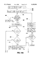
- FIGS. 7A and 7B are a flow chart depicting the details of the step that analyzes tool paths on FIG. 6, thereby creating a new "intermediate program" that includes no head-up/head-down movements by the laser head.
- FIG. 8 is a flow chart depicting an optional series of logical operations used in creating a new "intermediate program" in which at least one interference event requiring a head-up/head-down laser head movement is allowed to remain in the intermediate program.
- FIG. 9A depicts a graphical system using X-Y coordinates of a sheet material to be cut by a laser cutting machine in which the "sweep type" is an X-sweep, showing four (4) bands.
- FIG. 9B shows the direction of sweeping of a part being analyzed with an X-sweep using four (4) bands.
- FIGS. 9C and 9D are a flow chart showing the logical operational steps required to perform an X-sweep as part of the analysis of the tool path depicted in FIG. 6.
- FIG. 10A depicts a graphical system using X-Y coordinates of a sheet material to be cut by a laser cutting machine in which the "sweep type" is an Y-sweep, showing four (4) bands.
- FIG. 10B shows the direction of sweeping of a part being analyzed with an Y-sweep using four (4) bands.
- FIGS. 10C and 10D are a flow chart showing the logical operational steps required to perform an Y-sweep as part of the analysis of the tool path depicted in FIG. 6.
- FIG. 11A depicts a graphical system using X-Y coordinates of a sheet material to be cut by a laser cutting machine in which the "sweep type" is a Radial Pie sweep, showing six (6) bands.
- FIG. 11B shows the direction of sweeping of a part being analyzed with a Radial Pie sweep using six (6) bands.
- FIGS. 11C and 11D are a flow chart showing the logical operational steps required to perform a Radial Pie sweep as part of the analysis of the tool path depicted in FIG. 6.
- FIG. 12A depicts a graphical system using X-Y coordinates of a sheet material to be cut by a laser cutting machine in which the "sweep type" is a Radial Wave sweep, showing four (4) bands.
- FIG. 12B is a flow chart showing the logical operational steps required to perform an inside-out Radial Wave sweep as part of the analysis of the tool path depicted in FIG. 6.
- FIG. 13A depicts a graphical system using the X-Y coordinates of a sheet material to be cut by a laser cutting machine in which the "sweep type" is a outside-in Radial Wave sweep, showing three (3) bands.
- FIG. 13B is a flow chart showing the logical operational steps required to perform a outside-in Radial Wave sweep as part of the analysis of the tool path depicted in FIG. 6.
- FIGS. 14A, 14B, 14C, 14D, and 14E are a flow chart depicting the logical steps required to calculate lead-ins as part of the analysis of the tool path of FIG. 6.
- FIG. 15 is a top plan view of a sheet of material depicting an example of lead-in angles on cut-outs as determined by a conventional CAD/CAM software product.
- FIG. 16 is a top plan view of a sheet of material depicting an example of lead-in angles on cut-outs as determined by the present invention.
- FIG. 1 shows a laser cutting machine, generally designated by the index numeral 10, which is capable of moving the laser head in any direction parallel to the surface of a piece of sheet material that is to be cut into specific shapes.
- the laser head designated by the index numeral 20
- the laser head is a non-contact device which typically would maintain a precise distance when in its "down" position, such as 0.050 inches, from the tip of the laser head to the top surface of the sheet material being cut.
- other types of laser heads including “contact"-type heads could be utilized without departing from the principles of the present invention.
- the laser head 20 is mounted on a carriage so as to be able to move back and forth in a linear direction perpendicular to the longitudinal dimension of the main table of the laser cutting machine. As laser head 20 traverses in this perpendicular direction, an accordion-like curtain designated by the index numeral 22 can be compressed or extended, accordingly.
- the entire laser head carriage structure, designated by the index numeral 24, is also capable of movement in the longitudinal direction along the main axis of the machine 10, and an accordion-like curtain on either side of the laser head structure, designated by the index numerals 26 and 28, can either compress or expand, accordingly.
- the movements of laser head 20 are typically controlled by a sophisticated computing device, such as a programmable logic controller or a computer numerical controller, as designated by the index numeral 15.
- FIG. 1 a planar part made of a sheet material, generally designated by the index numeral 30, is placed on top of a special bed-like structure, indicated by the index numeral 32.
- Bed-like structure 32 is made up of an X-Y grid structure of relatively thin metal sheet material, which is constructed to create multiple "points" which support the bottom surface of the sheet material 30. These points, designated by the index numeral 34, can be seen on both FIGS. 1 and 2.
- a small air gap 36 is automatically maintained between the tip of laser head 20 and the top surface of the sheet material 30, as related above.
- this air gap is maintained at a spacing of 0.050 inches, and uses a capacitive sensor (not shown) to detect this distance and by use of a control circuit, keep it at a constant value when in the down position.
- a capacitive sensor not shown
- FIG. 2 when a piece of the sheet material 30 has been cut out, but fails to fall all the way to the bottom of the bed 32, it can become "hung up" on the top portion of the bed 32. This hung-up portion of the sheet material is viewed in FIG.
- FIG. 3 An example part made of sheet material (and designated by the index numeral 30) is depicted in FIG. 3, after it has been cut-out by laser cutting machine 10. It will be understood that the smaller areas that have been cut out by laser head 20 will typically fall to the bottom 42 of the bed structure 32, thereby causing no interference problems with laser head 20 as it continues to move over the surface of sheet material 30. On the other hand, some of the larger areas, such as the circle designated by the index numeral 38, can quite easily become "hung up" on the top surface 40 of the bed structure 32, thereby causing a potential interference problem with laser head 20.
- each of the cut-outs will have a minimum X-value and maximum X-value, and a minimum Y-value and maximum Y-value. For example, on FIG.
- the unusual cut-off shape 44 exhibits an X-minimum value, designated by the index numeral 50, an X-maximum value at 52, a Y-minimum value at 54, and a Y-maximum value at 56.
- These minimum and maximums values effectively create a rectangular "box" bounded by truncated line segments along lines 50, 52, 54, and 56 on FIG. 4B, which describe the smallest rectangle that cut-out 44 fits within while maintaining an orthogonal coordinate system (such as the X-Y coordinate system described above).
- the cut-out 44 depicted in FIG. 4A additionally shows the "center-X” and "center-Y” positions for the rectangular box defined by the X and Y minimums and maximums.
- the center-X position is designated by the index numeral 64, and is equal to the sum of the X-minimum value 50 and the X-maximum value 52, divided by 2 (and numerically represents an X-average).
- the center-Y position designated by the index numeral 66, is equal to the sum of the Y-minimum value 54 and the Y-maximum value 56, divided by 2 (and numerically represents a Y-average).
- the intersection of the center-X and center-Y positions defines a point, designated by the index numeral 68, which is known as the "centroid,” and which is used in many other calculations involving the present invention.
- FIG. 5A a circular cut-out shape designated by the index numeral 70 is depicted, and has a centroid at index numeral 72, which also happens to be the center of circle 70.
- a hole 74 is the desired location for the "pierce point” or “pierce location,” and the point 76 is the desired "end of cut.”
- any "dross” that may accumulate at the point the laser beam first pierces the sheet material should not be on the preferred cutting path (i.e., path 70), but preferably is to be located within a portion of the sheet material that is to be cut-out, and later discarded.
- the laser head is preferably positioned at the pierce point 74, and remains there until the laser beam has been turned on long enough to guarantee penetration through the sheet material.
- the laser head then will traverse from the pierce point 74 toward the desired cutting path 70, as depicted by the line 80.
- the laser is then moved in a controlled circular path, so as to perform the precise cut shown by the path 70.
- This path depicted by the index numeral 80 is known as the "lead-in,” and is found on virtually every laser cutting machine presently manufactured.
- the length of path 80 typically can be fixed at a distance according to the programmer's preference, such as a nominal distance of 0.050 inches, as designated by the letter "D" on FIG. 5A. In this manner, time is saved by not having to traverse the entire radius of the circle starting at its centroid 72, and then traversing along line segments 78 and 80.
- FIG. 5B A similar example for rectangular or square shapes is depicted in FIG. 5B, where the desired cut-out shape is designated by the index numeral 90.
- the centroid of this shape is located at index numeral 92
- the pierce point is designated by the index numeral 94
- the end-of-cut point is designated by the index numeral 96.
- the lead-in path is designated by the index numeral 100, and can be set to a nominal distance of 0.050 inches (i.e., at dimension "D"). It is preferred that the lead-in direction follow along the diagonal line segment defined by line segments 98 and 100 on FIG. 5B.
- the laser head would position itself at the pierce point 94 and start its burn. Once the sheet material has been penetrated, the laser head would move along line 100 until reaching the point 96, after which it would then move along the rectangular pathway 90 until again coming to the point 96, at which time the laser would turn off.
- the lead-in angles and linear distances could be adjusted to many other values for various shapes of cut-outs without departing from the principles of the present invention.
- the lead-in angle is always along either the X-axis or the Y-axis, which means that the lead-in angle will always be one of the following possible angular values: 0°, 90°, 180°, or 270°, with respect to the X-Y coordinate grid system.
- the lead-in angle can be defined by a diagonal line segment that extends from the centroid (such as centroid 92) to one of the corners of the cut-out (such as corner 96).
- the possible lead-in angles would be as follows: 45°, 135°, 225°, or 315°.
- a rectangular box shape be assumed when calculating the angle along which the lead-in will occur, unless such lead-in angles are impossible for a particular shape.
- the pierce point be located proximal to an intersection of line segments that make up cutting path, in which this intersection would have been chosen for the lead-in angle if the shape had been rectangular.
- the lead-in angle for square or rectangular shapes optionally can be restricted to angles that are parallel to the X- and Y-axes (i.e., at angles of 0°, 90°, 180°, or 270°), or to locations that bisect one of the linear sides of the cutting path for these shapes.
- a lead-in angle of 90° can be used, as depicted by the line segment 102, which represents a lead-in path that starts at a pierce point 104 and ends at a start-of-cut point 106.
- This alternative lead-in angle allows the corner radii to be uniform for all four corners of the cut-out without any otherwise necessary special programming to control the laser head at the point where the lead-in path joins the cutting path 90. This allows the programmer to choose locations other than a corner (or intersection) at which the inevitable "mark” (i.e., an irregularity in the cut) will appear on the cutting path or edge of the cut-out.
- CAD computer aided drafting
- This CAD file is then used by a CAD/CAM computer program, which then creates an initial "NC code” file (also called a “part program") that includes a first "tool path.”
- This file is an "intermediate” file which includes a tool path, however, it does not include every command needed to operate the laser cutter, and typically would not include such commands as head-up/head-down, start-cut, or stop-cut.
- the CAD/CAM computer program will add all of the necessary commands to the data file before this file is transferred to the laser cutting machine for actual execution.
- the present invention uses some of the same steps as used by conventional CAD/CAM systems, however, the initial tool path is analyzed many times over in an attempt to find the quickest possible way to implement the cutting processes for the particular sheet material part.
- the major steps to create this optimized tool path are described in flow chart form, and at a function block 110 a CAD file is first created for a particular part, and an initial NC code file (i.e., the initial CAD/CAM program data file) is created.
- an "intermediate" program is created that determines a tool path for this particular part.
- This intermediate program mainly consists of a data table for each cut-out which includes commands for the types of movements to be performed (e.g., rapid-travel movement, slower cutting movement in a straight line, a slower cutting movement in an arc, etc.), the necessary X and Y vectors, a set of values for each cut-out, including the maximum and minimum X and Y values, and many other types of information to control the actual movements of the laser head.
- commands for the types of movements to be performed e.g., rapid-travel movement, slower cutting movement in a straight line, a slower cutting movement in an arc, etc.
- the necessary X and Y vectors e.g., a set of values for each cut-out, including the maximum and minimum X and Y values, and many other types of information to control the actual movements of the laser head.
- data tables typically use a specific protocol that can be understood by a specific CAD/CAM
- Function block 114 the tool path created by the intermediate program is analyzed multiple times, and one or more "re-sequenced" tool paths are created that will require no head-up/head-down movements while avoiding previously cut areas on the sheet material part.
- Function block 114 is quite complex, and is described in greater detail hereinbelow, and includes flow charts that are described on FIGS. 7A, 7B, 9C, 9D, 10C, 10D, 11C, 11D, 12B, 13B, and 14A-14E.
- the next major step on FIG. 6 occurs at a function block 116 that selects the re-sequenced tool path that contains the minimum rapid-travel distance that the laser head must move. Once this tool path is known, the logic flow is directed to a function block 118 that creates a new part program data file containing NC code that uses the new tool path.
- the principles of the present invention can be applied either during post-processing of the NC code, or after all post-processing has been accomplished. It is preferred that the analysis steps concerning the tool path re-sequencing occur during post-processing, which allows the methodology of the present invention to be used after an initial tool path has been created by the CAD/CAM computer program, but before every required command has been inserted into the CAD/CAM data file.
- the "library files" containing various geometric shapes typically would be accessible for use in creating the re-sequenced tool paths while analyzing the initial tool path.
- the part program (which contains the optimal tool path) can be sent back to the CAD/CAM computer program which will then add all of the necessary commands to complete the NC code, and which will then be in a condition to be introduced directly to the laser cutting machine.
- a data table is created that contains information concerning all of the rectangular areas (or "boxes") that represent all of the X-minimum, X-maximum, Y-minimum, and Y-maximum values for each of the cut-outs in the intermediate program, at a function block 120.
- the type of sweep and the number of bands are selected, and the intermediate program is inspected to find the ending point of each cut-out.
- a new "re-sequenced" intermediate program is created which typically would include a new sort order.
- the term "sweep” represents the counting of how many cut-outs exist within a particular band
- the term “sort” is the step of determining the order in which the cut-outs would be cut within this band, and a “sort” also calculates the rapid-travel distance incurred within that band.
- the maximum number of bands is typically in the range of twenty (20) to thirty (30) bands, and it is preferred that this number be adjustable by a human user via some type of keyboard entry device that communicates with a computer system (e.g., such as computer 15) performing these operations. Furthermore, it is preferred that all sweep types start with one (1) band, and then increase the number of bands (preferably incrementally) until reaching the maximum number of bands desired for these analysis steps. It will be understood that the purpose of the flow chart on FIGS. 7A and 7B is to determine a re-sequenced tool path that will require zero head-up/head-down movements.
- a "back-up"-mode analysis will preferably be performed, which will also look to find the minimum number of head-up/head-down movements, as described on FIG. 8, below.
- the logic flow is directed to a function block 124 that, in reverse order of the sort, creates a modified intermediate program while choosing a preferred lead-in direction and ending point for each cut-out. Furthermore, new locations of all rapid-travel paths will be created.
- the rapid-travel path movements for this sweep are analyzed to determine whether or not any of these paths will pass over any pre-cut feature.
- the decision is made whether or not this particular intermediate program is valid, i.e., contains no rapid-travel path movements that pass over any pre-cut feature.
- the logic flow is directed to a function block 130 which discards this possibility. In that event, the logic flow is directed to a letter "A", which takes the logic flow over to FIG. 7B, and arrives at a decision block 136 that determines whether or not this is the final attempt to sweep the intermediate program.
- the logic flow is directed to a letter "B", which directs the logic flow to a function block 132 on FIG. 7B.
- function block 132 the most recent valid possibility is compared to a previously-stored valid possibility. In this comparison, the lower cumulative rapid-travel distance is sought.
- function block 134 the better possibility is saved, and the worse possibility is discarded. It will be understood that the better possibility typically is the one containing the lower amount of rapid-travel distance.
- the logic flow now arrives at decision block 136, and if the most recent possibility was the final attempt to sweep the intermediate program, then the logic flow passes out the YES answer and this series of operations has been completed. If the answer was NO at decision block 136, the logic flow is directed to a function block 138 that requires a new sweep with a different number of bands or sweep type to be performed. The logic flow then is directed to a letter "C", which brings the logic flow back to the starting point at the top of FIG. 7A. The details of the types of sweeps, number of bands, creating a new sort order, and creating preferred lead-in directions for each cut-out are all described in greater detail hereinbelow.
- a function block 140 is the beginning point for this optional re-analysis of the part to be cut.
- the type of sweep and number of bands is selected, the intermediate program is inspected to find the ending point of all cut-outs, and a re-sequence intermediate program is created.
- a modified intermediate program is created while choosing the preferred ending point for each cut-out. New locations of all rapid-travel paths are also created.
- the next step, at a function block 146, is to analyze all rapid-travel path movements to determine how many interference events occur where the laser head must pass over a pre-cut feature.
- the latest possibility (P1) is compared to the previously-stored possibility (P2).
- P1 the latest possibility
- P2 the previously-stored possibility
- the better possibility is saved, and the worse possibility is discarded.
- the time required to perform the head-up/head-down movements is compared to the time required to perform the additional rapid-travel movements.
- the logic flow now arrives at a decision block 152 which determines whether or not this was the final attempt to sweep the intermediate program. If the answer is YES, then the flow chart on FIG. 8 is completed. If the answer was NO, then the logic flow is directed to a function block 154 that causes a new sweep to be performed using a different number of bands or a different sweep type. The logic flow is then directed back to function block 140.
- FIG. 9A shows a representative part to be cut, designated by the index numeral 160, in which the dotted lines represent the boundary of bands used during an X-sweep.
- the number of bands initially starts at one (1), however, in the illustrated example of FIG. 9A, there are four (4) bands. Since the sweep will be in the X-axis, the longitudinal dimension of each band will also be parallel to the X-axis.
- the bands preferably are chosen to have equal width, and band #1 extends from the bottom of the part (as viewed on FIG. 9A) to the dotted line 162, band #2 extends between lines 162 and 164, band #3 extends between lines 164 and 166, and band #4 extends between lines 166 and 168.
- the sweep merely counts how many cut-outs are within each band, and this is done by locating a reference point (which could be either the start-of-point or the centroid) of each of the cut-outs, as determined by the reference point's X- and Y-coordinates.
- band #1 for example, include all Y-values greater than or equal to zero and less than the value Y 1 , in which Y 1 is equal to the value at line 162. Using this convention, band #2 would include all Y-values greater than or equal to Y 1 and less than Y 2 , which is at line 164.
- Band #3 correspondingly, would include all Y-values greater than or equal to Y 2 , and less than Y 3 (at line 166).
- Band #4 would correspondingly include all Y-values greater than or equal to Y 3 , and less than Y 4 , which is the top edge of the part at line 168.
- Y 2 at line 164
- those circles would be counted as members of band #3, and not band #2.
- FIG. 9B a similar part 174 is depicted, and again four bands for an X-sweep are illustrated.
- the X-sweep for band #1 is set to a default value of the "X-plus” direction, meaning that the sweep of band #1 starts at its minimum X-value, and moves along band #1 toward its maximum X-value. Accordingly, the direction of the sweep, as represented by the line with arrows 176, moves from left-to-right on FIG. 9B within band #1.
- the sweep finishes band #1, then moves to band #2 to sweep in the X-minus direction until finishing at the X-minimum value for band #2.
- the sweep then continues at band #4 for the last X-direction sweep, in the X-plus direction. Band #3 was skipped during this sweep because there were no cut-outs within that band.
- FIGS. 9C and 9D represent a flow chart that describes the methodology for performing an X-sweep.
- the flow chart starts at a function block 180 in which the number of bands is set equal to one (1), and the sort direction is set to X-plus. It will be understood that a data table containing information regarding each cut-out of the part has already been created, and that the original CAD/CAM data file has already produced a sort order of these cut-outs. While each sweep is performed according to the principles of the present invention, the rapid-travel distance is determined and stored, the sort order is determined (typically re-sequenced) and stored, and this all occurs for each sweep type and for each number of bands in that type of sweep.
- the present invention temporarily eliminates the lead-in coordinate because a new lead-in location typically will be chosen for each of the cut-outs.
- conventional CAD/CAM computer programs generally choose the same direction for all lead-ins for all cut-outs on the entire part (see FIG. 15), whereas the present invention will choose lead-ins having multiple directions when considering all of the cut-outs on the entire part (see FIG. 16), and this will be discussed in greater detail hereinbelow.
- the part is divided into "N" number of bands, by taking the minimum and maximum Y-dimensions and dividing the part up into equal segments along the Y-axis.
- the value for N is set equal to one (1), however, for later sweeps the value for N will be greater than one (1).
- the band number is set equal to one (1).
- a function block 186 the list of cut-outs in the data table is inspected, and all cut-outs in the current band are found.
- a decision block 188 it is determined whether or not there were any cut-outs in the current band. If the answer is YES, the logic flow is directed to a function block 190 that "sorts" all of the cut-outs in the current band according to the sort direction (i.e., either X-plus or X-minus). After this has occurred, a function block 192 changes the sort direction, and the logic flow proceeds to a decision block 196 which determines whether or not there are any more bands to be sorted.
- the sort direction i.e., either X-plus or X-minus
- the logic flow travels to a function block 194 that instructs the system to not change the sort direction.
- the logic flow again arrives at decision block 196 to determine whether or not there are any more bands to be analyzed. If the answer is YES, the logic flow is directed to a function block 198 in which the current band number is incremented. The logic flow then is directed back to function block 186 to analyze the list of cut-outs in the (new) current band.
- function block 200 the re-sequenced program is analyzed (using the new sort order of cut-outs after all bands have been swept for the entire part). In addition, function block 200 checks for any interference problems and calculates the total rapid-travel distance. After this has been accomplished, the logic flow travels to a function block 202 to increment the number of bands. For example, if the number of bands previously was set to four (4), then the number of bands is incremented to the value of five (5).
- the logic flow now travels to a decision block 204 that determines whether or not the maximum number of bands has been reached. This is a value that is pre-determined by a human user, and would typically be in the range of twenty (20) to thirty (30) bands. If, for example, the maximum number of bands had been previously set to a value of twenty-five (25), and a sweep having four (4) bands has just been completed, which was incremented to the value of five (5) at function block 202, then the maximum number of bands would not have yet been reached. Under this circumstance, the logic flow leaves the NO output from decision block 204 and is directed to the letter "B", which further directs the logic flow back to FIG. 9C and to function block 182.
- the logic flow is directed out the YES output of decision block 204 and arrives at a function block 206, which instructs the system to go to the next type of sweeping for re-sequencing. For example, at the end of the X-sweep, the next type of sweeping would likely be a Y-sweep.
- FIG. 10A shows a part depicted by the index numeral 210 that has been divided up into four (4) bands for a Y-sweep.
- Band #1 extends from the left-hand edge (as viewed in FIG. 10A) to the dotted line 212
- band #2 extends from line 212 to line 214
- band #3 extends from line 214 to line 216
- band #4 extends from line 216 to the right-hand edge of the party, at 218.
- band #1 include X-values greater than or equal to zero, and less than a value X 1 at line 212.
- band #2 should include reference points located greater than or equal to X 1 and less than X 2 (at line 214), etc.
- While performing a sweep it is preferred to set the sweep direction in band #1 to the Y-plus direction, as is indicated by the line 222 on FIG. 10B for the first band of part at index numeral 220. Since the sweep direction is Y-plus in band #1, the sweep direction in band #2 would be Y-minus, and the sweep direction in the next band that contained any cut-outs would be in the Y-plus direction. If band #3 had no cut-outs, as shown in FIG. 10B, then there would be no sweep performed in band #3, and the sweep path would travel from band #2, then along line 224 all the way to band #4.
- the Y-sweep begins by starting with a single band and the sort direction set to Y-plus.
- the width of the part is divided into "N" number of bands, although for the first pass, there of course is only one (1) band.
- the Y-sweep also starts with band #1.
- the data table of cut-outs is inspected to find all having reference points within the current band.
- a function block 240 sorts all of these cut-outs in the current band according to the sort direction (as exemplified by the directional lines in FIG. 10B).
- the sort direction is changed, and the logic flow is then directed to a decision block 246 that determines whether or not there are any more bands to do in this particular sweep.
- the logic flow is directed to a function block 244 that prevents the sort direction from being changed.
- the logic flow arrives at decision block 246 to discover whether or not there are more bands to do. If the answer is YES, the logic flow is directed to a function block 248, which increments the current band number, and then directs the logic flow back to function block 236. If the answer at decision block 246 is NO, the logic flow is directed to a letter "A" that then directs the logic flow to a function block 250 on FIG. 10D.
- an analysis of the re-sequenced program is performed, while checking for any interference problems and calculating the total rapid-travel distance.
- the next step is to increment the number of bands, at a function block 252.
- a decision block 254 determines whether or not the maximum number of bands has been reached, which was previously set by the human user (or was set by a default value), to a number such as twenty-five (25). If the answer is NO, the logic flow is directed to a letter "B" which takes the logic flow back to function block 232 on FIG. 10C. If the answer is YES, then the logic flow is directed to a function block 256 that directs the program to the next "sweep-type" of sequencing.
- FIG. 11A depicts a part designated by the index numeral 260 which is to be re-sequenced using a Radial Pie sweep.
- Band #1 consists of the "pie slice” between 0° and 60°.
- band #2 comprises the pie slice between 60° and 120°
- band #3 comprises the pie slice between 120° and 180°
- band #4 comprises the pie slice between 180° and 240°
- band #5 comprises the pie slice between 240° and 300°
- band #6 comprises the pie slice between 300° and 0°.
- the origin for the X-Y axes preferably is set at the centroid of the entire part 260, at the location designated by the index numeral 262.
- band #1 preferably includes all angles greater than or equal to 0° and less than 60°.
- band #2 would include all angles greater than or equal to 60° and less than 120°.
- the sweep directions for part 260 are depicted.
- the sweep direction is from the 0° axis (at index numeral 264) and moves in a positive angular direction (i.e., counterclockwise) throughout a 360° angle, until arriving back at the 0° axis 264.
- the spiral shaped set of arrows, designated by the index numeral 266, generally shows the order in which the bands are swept.
- there are six bands (each being 60° in arc length), however, the number of bands can range from one (1) through twenty (20) or thirty (30), depending upon the value entered by the human user as to the maximum number of bands for the Radial Pie sweep type.
- the sort direction depends upon the location of the "end-angle" for each band with respect to angles that are 45° from either the 0° axis or the 180° axis.
- angle boundaries at 45° see dashed line 268), 135° (see dashed line 270), 225° (see dashed line 272), and 315° (see dashed line 274) control the direction that sorting takes place regardless of the number of bands used. This is described in greater detail in the flow chart in FIGS.
- the sort direction for band #1 would be X-minus (see arrow 284)
- the sort direction for band #2 would also be X-minus (see arrow 286)
- the sort direction for band #3 would be Y-minus (see arrow 288)
- the sort direction for band #4 would be X-plus (see arrow 290)
- the sort direction for band #5 would also be X-plus (see arrow 292)
- the sort direction for band #6 would be Y-plus (see arrow 294).
- FIGS. 11C and 11D represent a flow chart for Radial Pie sweeps.
- the number of bands is set equal to one (1).
- the band number is set equal to one (1), regardless of the value of N.
- the current band is inspected to find all cut-outs within that band at a function block 306. It is preferred that the reference point of each cut-out be used to determine its location within a particular band, however, another basis for determining precisely where each cut-out lies within the structure of bands could be used, such as finding the geometric center (i.e., the centroid) of the cut-out.
- a decision block 308 it is determined whether or not any cut-outs exist within the current band. If the answer is YES, the logic flow is directed to another decision block 310 that determines whether or not the band end-angle is between the values of 45° and 315°. If the answer is YES, function block 312 sets the sort direction as Y-plus.
- the logic flow is directed to a decision block 314 that determines whether or not the band end-angle is between the values of 45° and 135°. If the answer is YES, then a function block 316 sets the sort direction to X-minus. If the answer at decision block 314 was NO, the logic flow travels to a letter "A", which takes the logic flow to a decision block 318 on FIG. 11D.
- Decision block 318 determines whether or not the band end-angle is between 135° and 225°. If the answer is YES, a function block 320 sets the sort direction to Y-minus. If the answer at decision block 318 was NO, then the sort direction is set to X-plus, at a function block 322. If the logic function arrives at function block 322, it can be accurately presumed that the band end-angle fell within the range of 225 degrees to 315 degrees. Once the sort direction has been determined, the logic flow on FIG. 11D is directed to a letter "B", which arrives at a decision block 324 on FIG. 11C. Furthermore, if the sort direction was determined by either decision block 310 or 314 on FIG. 11C, the logic flow is directed to the same decision block 324, or if there were no cut-outs in the current band (leading to a NO result at decision block 308).
- decision block 324 it is determined whether or not there are any more bands to be done. If the answer is YES, then the logic flow travels to a function block 326 that increments the current band number, and then further directs the logic flow back to function block 306. If decision block 324 answers NO, then the logic flow travels to a function block 328 which performs an analysis of the re-sequenced program, including checking for interferences and calculating the total rapid-travel distance.
- the next step is to increment the number of bands, at a function block 330.
- the logic flow then arrives at a decision block 332, which determines whether or not the maximum number of bands has been reached. If the answer is NO, the logic flow is directed back to function block 302. If the answer is YES, the logic flow is directed to a letter "C" which directs the logic flow onto FIG. 11D at a function block 334.
- the control system is instructed to go to the next sweep-type of sequencing.
- FIG. 12A another part made of sheet material, generally designated by the index numeral 270, is depicted.
- the type of sweep used in FIG. 12A is known as an "inside-out Radial Wave," in which each band is one of the concentric circles having a center at the centroid 272 of part 270.
- the outermost band i.e., band #4 on FIG. 12A
- part 270 has a rectangular shape
- the outer circle (at numeral 280) will intersect all four corners of this part, however, it will be understood that parts having other shapes could be used in which the outermost circle of the outermost band would intersect with the part at only a single point.
- each of the concentric circles used in a Radial Wave sweep should have a radius that is incrementally larger by an equal amount as compared to the radius of the circle directly adjacent to the innermost edge of a particular band.
- the radius of the circle designated by the index numeral 274 i.e., for band #1
- the radius for the next larger circle at index numeral 276 should be equal to the dimension 2R.
- the dimension for the next larger circle, at index numeral 278, should have a radius equal to the dimension 3R
- the outermost circle at index numeral 280 should have a radius equal to the dimension 4R.
- each of the arcuate paths defined by the bands will have an equal "width" when traveling along any one of the bands upon crossing a particular angle (such as 0°).
- the preferred sorting direction for each of the bands in FIG. 12A is in order of increasing angular value, i.e., in the counterclockwise direction, as shown by the dashed arrow 282. Therefore, when sweeping through band #2, the four (4) smaller circles that are to become cut-outs, designated by the letters "a”, "b", “c", and "d” will be sorted in the order a-b-c-d.
- each of the cut-outs will be sorted according to only a single point on the X-Y coordinate system having a center origin (at the point 272 on FIG. 12A).
- This single point for each cut-out could be located at the centroid of the cut-out, or a reference point located at the start-of-cut point of the cut-out.
- Such a start-of-cut point is equivalent to the point defined by the index numeral 76 on FIG. 5A, or the index numeral 96 on FIG. 5B, for example.
- the "start-of-cut point" is the location of the cutting path where the laser beam initially touches the cutting path.
- the start-of-cut point is the same location as the end-of-cut point.
- FIG. 12B is a flow chart that describes the logical steps required to perform a Radial Wave sweep from the inside-out, starting with a function block 290 that sets the number of bands equal to a value of one (1). After that, the distance from the centroid of the part 270 to its farthest corner is determined at a function block 292, and then divided by "N" number of bands to determine the band boundaries. As in the case with other types of sweeps, a convention should be chosen to determine precisely where each band will start and stop at boundaries between bands. For example, it is preferred that band #1 comprise the circle having a radius greater than or equal to zero and a radius less than the dotted circle 274.
- band #2 preferably will comprise the area greater than or equal to the radius of circle 274, and less than the circle 276.
- Bands #3 and #4 will correspondingly include the areas greater than or equal to the circle 276 and less than the circle 278 (for band #3), and the area greater than or equal to the circle 278 and less than the circle 280 (for band #4). All of these calculations and logical decisions take place according to function block 292.
- the band number is set equal to one (1), regardless of the value for N.
- the data table containing the numeric information for all of the cut-outs is inspected to ascertain all cut-outs that exist within the current band.
- the cut-outs within the current band are sorted according to angular position of the reference point for each cut-out (e.g., at the cut-out's centroid, or at its start-of-cut point), and this sort occurs in order of positive angle starting at the 0° axis.
- the logic flow then travels to a decision block 302.
- the logic flow also arrives at decision block 302, where it is determined whether or not any more bands remain to be sorted. If the answer is YES, a function block 304 increments the current band number, and the logic flow is directed back to function block 296. If the answer was NO at decision block 302, then the re-sequenced program is analyzed to determine whether or not any head-up/head-down operations are required, and also the cumulative amount of rapid-travel distance is ascertained, at a function block 306. After this occurs, a function block 308 increments the number of bands. A decision block 310 now determines whether or not the maximum number of bands has been reached. If the answer is NO, the logic flow is directed back to function block 292. If the answer is YES, the logic flow is directed to a function block 312, which instructs the system to undergo further sequencing with the next type of sweep.
- FIG. 13A shows a part designated by the index numeral 320 that is to be analyzed using an "outside-in Radial Wave" sweep.
- three (3) bands are laid out as concentric circles having their center at the centroid of part 320, which is the point designated by the index numeral 322.
- the radius of the outermost circle, designated by the index numeral 324 preferably is of the precise length so as the circumference of circle 324 will intersect the outermost corner of part 320. Since part 320 is depicted as a rectangle in FIG. 13A, circle 324 will intersect part 320 at each of its four corners.
- Band #1 preferably will include the area of the circle having a radius greater than or equal to zero and less than the circle designated by the index numeral 328. Using this same convention, band #2 will include the area greater than or equal to the radius at circle 328 and less than the radius at circle 326. Similarly, band #3 will include the area greater than or equal to the circle 326 and less than the circle 324. All cut-outs that fall within these various circle segments will be analyzed according to which of the individual bands the cut-outs fall within.
- the incremental radius between bands be equal, i.e., if the radius between the origin 322 and circle 328 is equal to the dimension "R,” then the radius between the origin 322 and circle 326 should be equal to the dimension 2R, and the radius between the origin 322 and the circle 324 should be equal to the dimension 3R.
- the sort order be according to an increasing angle (i.e., counterclockwise on FIG. 13A), as indicated by the dashed arrow 330.
- the sorting for each band begin at the zero angle, or in other words, along the positive X-axis. Using this convention, then the four small circles designated by the letters "a”, "b”, “c”, and "d” would be sorted in the order a-b-c-d.
- each cut-out can be made as according to one of many various schemes, and preferably, the reference point for each cut-out will be set to its start-of-cut point. Of course, other logical points for each cut-out could be used instead, such as the centroid of each cut-out. Using this convention, all of the circles a, b, c, and d would fall within band #1 on FIG. 13A.
- FIG. 13A depicts an outside-in Radial Wave
- the sorting of these bands will be in the order of band #3, band #2, and then band #1.
- this may logically seem no different from an inside-out Radial Wave sweep, however, since the order of sorting from cut-out to cut-out will ultimately control the movements of the laser head 20, it could make a significant difference as to the precise location the head movements begin with respect to the part 320.
- FIG. 13B is a flow chart describing the logical operational steps for the outside-in Radial Wave sweep type, beginning with a function block 340 that begins with a single band (or, in other words, sets the value for N equal to one (1)). At a function block 342, the distance from the centroid 322 of the part 320 is measured to the farthest corner of the part, and divided by the present value of the quantity "N" to determine the boundaries between the bands.
- band "N” is the opposite as described in FIG. 12B where the system started with band #1.
- the value for N would be set equal to three (3), so function block 344 would set the system to look at band #3.
- a function block 346 would inspect the data table that contained the numeric data for all of the cut-outs of part 320 in order to find all cut-outs that reside within the current band.
- a decision block 348 it would be determined whether or not there were any cut-outs within the current band. If the answer is YES, then a function block 350 will sort the cut-outs according to a positive angle (i.e., counterclockwise), starting at the 0° angle (i.e., at the positive X-axis). After that has occurred, the logic flow is directed to a decision block 352.
- a function block 356 will analyze the re-sequenced program of cut-outs, to determine whether or not there are any head-up/head-down movements required, and to determine the cumulative total of all rapid-travel distance. After that has occurred, a function block 358 will increment the number of bands. A decision block 360 then determines whether or not the maximum number of bands has been reached. This maximum number of bands would typically be set to a value in the range of twenty (20) to thirty (30), and can be adjusted by a human user. If the answer is NO, the logic flow is directed back to function block 342. If the answer was YES, the logic flow is directed to a function block 362 which instructs the system to continue sequencing with the next sweep-type (if any).
- an optimal re-sequenced program will have been determined, as according to function block 116 on FIG. 6. To be able to arrive at this function block 116 assumes that a re-sequenced tool path was found that contains no head-up/head-down operations. Otherwise, the optional sequencing would be invoked to arrive instead at function block 150 on FIG. 8. In either case, the "best" possibility should include the minimum amount of rapid-travel distance to perform all of the cut-outs on a particular part, although at function block 150, the more important quantity is likely to be the minimum number of interferences which would require a head-up/head-down operation.
- FIGS. 14A-14E depict a flow chart that describes the preferred way for creating a new set of lead-ins for these cut-outs.
- a "TO" pointer is set to be equal to the "last" internal cut-out, which refers to the pierce point for the current optimal re-sequenced program sort order.
- a "FROM” pointer is set to the "second-to-last" internal cut-out location. This cut-out location in function block 402 is also at the pierce point, for the second-to-last cut-out.
- the TO-pointer and FROM-pointer represent the starting and stopping points of a particular rapid-travel movement by laser head 20. These motions by laser head 20 will be analyzed with respect to the X-axis and Y-axis, much as was depicted on FIG. 3 for a particular part. Accordingly, the TO-pointer and FROM-pointer each have a co-ordinate on the X-Y plane, so each of these pointers has an X-value and a Y-value.
- a decision block 404 determines whether or not the "X" distance between the FROM-pointer and TO-pointer is greater than the "Y" distance. If the answer is YES, then the precedence is set to "X-Precedence,” by a function block 406. On the other hand, if the answer was NO, then a function block 408 sets the precedence to "Y-Precedence.”
- a decision block 410 determines if the "X" direction is positive. If the answer is NO, then the logic flow travels to a letter "A" which directs the logic flow to FIG. 14B, described in greater detail hereinbelow. If the answer at decision block 410 was YES, then the logic flow travels to another decision block 412 which determines whether or not the "Y" direction is positive. If the answer is YES, then the logic flow travels to a letter "B" which directs the logic flow to FIG. 14E, described in greater detail hereinbelow.
- a function block 414 sets the lead-in location for the second-to-last cut-out to quadrant #4. It will be understood that, for the illustrated example in FIGS. 14A-14E, all of the cut-outs have a circular shape. Now that quadrant #4 has been selected, function block 414 will set the angle equal to 0° if the precedence type is X-Precedence, and will set the angle equal to 270° if the precedence type is Y-precedence. After that has occurred, the logic flow travels to a decision block 416.
- a function block 418 sets the TO-pointer to the cut-out that was pointed to by the FROM-pointer (i.e., the immediately previous cut-out in the sort order).
- a function block 420 then decrements the FROM-pointer to the preceding cut-out in the part program. The logic flow is then directed back to decision block 404.
- decision block 410 determines that the X-direction is negative, then the logic flow is directed to a decision block 422 on FIG. 14B, via the letter "A.” Decision block 422 now determines whether or not the Y-direction is negative, and if the answer is NO, the logic flow is directed to a letter "D" which directs the logic flow to FIG. 14C, discussed in greater detail hereinbelow.
- the logic flow is directed to a function block 424 that sets the lead-in location to quadrant #3.
- the lead-in angle is set depending upon precedence type, and if X-Precedence, the angle is set to 180°; on the other hand, if Y-Precedence, the angle is set to 270°.
- the distance is now calculated between the "FROM" cut-out and "TO" cut-out, and this distance is saved as a variable named "D3.”
- a function block 428 now sets the lead-in location to quadrant #4, and if X-Precedence, the angle is set equal to 0°. If Y-Precedence, the angle is set to 270°.
- a function block 430 now calculates the distance between the FROM cut-out and the TO cut-out, and saves this distance as a variable "D4.” At a decision block 432, it is determined whether or not the value for D3 is less than or equal to the value for D4. If the answer is NO, then the lead-in location is set to quadrant #4, and for X-Precedence, the angle is set to 0°; for Y-Precedence, the angle is set to 270°, by a function block 434.
- a function block 438 sets the lead-in location to quadrant #2, and the lead-in angle is set equal to 180° if X-Precedence, or 90° if Y-Precedence.
- a function block 440 then calculates the distance between the FROM cut-out and the TO cut-out, and saves that distance as a variable "D2.”
- a function block 442 now sets the lead-in location to quadrant #1, and sets the angle to 0° if X-Precedence, or to 90° if Y-Precedence. The distance is calculated between the FROM cut-out and the TO cut-out, and that distance is saved as a variable "D1," at a function block 444.
- the lead-in location is now set to quadrant #3 at a function block 446.
- the angle is set to 180° if X-Precedence, or to 270° if Y-Precedence.
- the distance between the FROM cut-out and the TO cut-out is determined, and this distance is saved as the variable "D3.”
- the logic flow now travels to the letter "E”, which directs the logic flow to a decision block 450 on FIG. 14D.
- a function block 452 sets the lead-in location to quadrant #2. If at X-Precedence, the angle is set to 180°, and if at Y-Precedence, the angle is set to 90°.
- a function block 456 will set the lead-in location to quadrant #1. If at X-Precedence, the angle is set equal to 0°, and if at Y-Precedence the angle is set to 90°. If the answer at decision block 454 was NO, then a function block 458 sets the lead-in location to quadrant #3. If at X-Precedence, the angle is set equal to 180°, and if at Y-Precedence the angle is set to 270°. The logic flow is now directed to the letter "C", which directs the logic flow back to decision block 416 on FIG. 14A.
- a function block 460 sets the lead-in location to quadrant #1. If at X-Precedence, the angle is set equal to 0°, and if at Y-Precedence the angle is set to 90°.
- a function block 462 calculates the distance between the FROM cut-out and the TO cut-out. This distance is saved as the variable "D1.”
- a decision block 464 now sets the lead-in location to quadrant #4, and if at X-Precedence the angle is set to 0°, and if at Y-Precedence the angle is set to 270°.
- a function block 466 now calculates the distance between the FROM cut-out and the TO cut-out, and saves this distance as the variable "D4.”
- a decision block 468 now determines whether or not D1 is less than or equal to D4. If the answer is YES, a function block 470 sets the lead-in location to quadrant #1. If at X-Precedence, the angle is set to 0°, and if at Y-Precedence the angle is set equal to 90°.
- a function block 472 sets the lead-in location to quadrant #4. If at X-Precedence, the angle is set equal to 0°, and if at Y-Precedence the angle is set equal to 270°. At this point in the flow chart of FIGS. 14A-14E, all possibilities for angular locations for the lead-in have been analyzed, and the logic flow is now directed back to the letter "C", which directs the logic flow to decision block 416 on FIG. 14A.
- the possible lead-in angles used in the illustrated embodiment i.e., 0°, 90°, 180°, or 270° for circular cut-outs, could have been chosen at other angular values without departing from the principles of the present invention.
- the lead-in angles for other shapes could be chosen at angular values other than along a diagonal (e.g., 45°, 135°, 225°, or 315° for squares), or at angular values other than along an orthogonal axis (such as 0°, 90°, 180°, or 270°, e.g., for ellipses) without departing from the principles of the present invention.
- FIG. 15 depicts an example of lead-in angles as determined by a conventional CAD/CAM software product, and it can be easily seen that each cut-out has a lead-in angle that is identical to each of the other lead-in angles. This is true for both circular lead-in cut-outs (e.g., see cut-out 500), and rectangular cut-outs (e.g., see cut-out 502). This is also true regardless of which of the cut-outs is the starting point or the ending point.
- FIG. 16 shows an example of lead-in angles as determined by the present invention.
- the lead-in angles can be quite different between various cut-outs.
- the circular cut-outs have lead-in angles that correspond to either the X-axis or the Y-axis
- the rectangular shapes have lead-in angles that correspond to the angle of the diagonal line that bisects the rectangles.
- the cut-out at the "start" point i.e., the cut-out 510
- the lead-in angle at cut-out 512 is "aimed” at the next shape to be cut out, i.e., cut-out 514.
- Laser head 20 would make the cut-outs in the following order: starting at cut-out 510, it would continue on to other cut-outs 512, 514, 516, 518, 520, 522, 524, 526, 528, 530, and finally the ending cut-out 532.
- the lead-in angle is generally "aimed" to the "next" cut-out, and the purpose of this is to ensure that laser head 20 will not attempt to rapid-travel directly over the cut-out that was just made.
- laser head 20 will proceed at rapid-travel speed directly to the right (as seen on FIG. 16) from the end-of-cut point 540 of cut-out 512 to the rectangular box surrounding the shape of cut-out 514. More specifically, laser head 20 will be commanded to rapid-travel from the end-of-cut point 540 for cut-out 512 to the pierce point 542 of cut-out 514.
Abstract
Description
Claims (60)
Priority Applications (2)
| Application Number | Priority Date | Filing Date | Title |
|---|---|---|---|
| US08/723,918 US6128546A (en) | 1996-09-30 | 1996-09-30 | Method and apparatus for a cutting system for avoiding pre-cut features |
| US09/672,357 US6609044B1 (en) | 1996-09-30 | 2000-09-28 | Method and apparatus for a cutting system for avoiding pre-cut features |
Applications Claiming Priority (1)
| Application Number | Priority Date | Filing Date | Title |
|---|---|---|---|
| US08/723,918 US6128546A (en) | 1996-09-30 | 1996-09-30 | Method and apparatus for a cutting system for avoiding pre-cut features |
Related Child Applications (1)
| Application Number | Title | Priority Date | Filing Date |
|---|---|---|---|
| US09/672,357 Continuation US6609044B1 (en) | 1996-09-30 | 2000-09-28 | Method and apparatus for a cutting system for avoiding pre-cut features |
Publications (1)
| Publication Number | Publication Date |
|---|---|
| US6128546A true US6128546A (en) | 2000-10-03 |
Family
ID=24908248
Family Applications (2)
| Application Number | Title | Priority Date | Filing Date |
|---|---|---|---|
| US08/723,918 Expired - Lifetime US6128546A (en) | 1996-09-30 | 1996-09-30 | Method and apparatus for a cutting system for avoiding pre-cut features |
| US09/672,357 Expired - Fee Related US6609044B1 (en) | 1996-09-30 | 2000-09-28 | Method and apparatus for a cutting system for avoiding pre-cut features |
Family Applications After (1)
| Application Number | Title | Priority Date | Filing Date |
|---|---|---|---|
| US09/672,357 Expired - Fee Related US6609044B1 (en) | 1996-09-30 | 2000-09-28 | Method and apparatus for a cutting system for avoiding pre-cut features |
Country Status (1)
| Country | Link |
|---|---|
| US (2) | US6128546A (en) |
Cited By (39)
| Publication number | Priority date | Publication date | Assignee | Title |
|---|---|---|---|---|
| US6284999B1 (en) * | 1999-07-23 | 2001-09-04 | Lillbacka Jetair Oy | Laser cutting system |
| US6300592B1 (en) | 1999-07-23 | 2001-10-09 | Lillbacka Jetair Oy | Laser cutting system |
| US6326586B1 (en) | 1999-07-23 | 2001-12-04 | Lillbacka Jetair Oy | Laser cutting system |
| US6376798B1 (en) | 1999-07-23 | 2002-04-23 | Lillbacka Jetair Oy | Laser cutting system |
| US20030009260A1 (en) * | 2000-01-17 | 2003-01-09 | Yoichi Tanaka | Positioning control method and positioning control device, and electronic part mounting device using this |
| US20030033049A1 (en) * | 2000-03-31 | 2003-02-13 | Incs Inc. | Data generating device, data generating method and data generating program |
| US6588738B1 (en) | 1999-07-23 | 2003-07-08 | Lillbacka Jetair Oy | Laser cutting system |
| EP1348511A1 (en) * | 2002-03-28 | 2003-10-01 | Fanuc Ltd | Laser machining method and apparatus therefor |
| US20040069755A1 (en) * | 2001-06-01 | 2004-04-15 | Georges Eftymiades | Method for the production of metal profiles |
| US20050116396A1 (en) * | 2003-01-09 | 2005-06-02 | Lemasson Gilles | Slat for laser cutting machine table |
| US20050172764A1 (en) * | 2004-02-10 | 2005-08-11 | Matthew Fagan | Method and system for eliminating external piercing in NC cutting of nested parts |
| US20050184036A1 (en) * | 2000-05-16 | 2005-08-25 | Gsi Lumonics Corporation | Method and system for precisely positioning a waist of a material-processing laser beam to process microstructures within a laser-processing site |
| US20050237019A1 (en) * | 2001-06-01 | 2005-10-27 | Thyssen Laser-Technik Gmbh | Method and device for the robot-controlled cutting of workpieces to be assembled by means of laser radiation |
| US20060161274A1 (en) * | 2005-01-17 | 2006-07-20 | Mitutoyo Corporation | Position control device, measuring device and machining device |
| US20090057279A1 (en) * | 2007-08-31 | 2009-03-05 | Rolls-Royce Plc | Method of cutting with a laser |
| US20090082892A1 (en) * | 2007-09-21 | 2009-03-26 | The Boeing Company | Optimizing non-productive part motion in an automated tape laydown machine |
| US20090084486A1 (en) * | 2007-09-27 | 2009-04-02 | The Boeing Company | Optimized ordering of doubler plies in composite structures |
| US20090196699A1 (en) * | 2008-02-05 | 2009-08-06 | Amr Elfizy | Method for drilling holes according to an optimized sequence |
| FR2928570A1 (en) * | 2008-03-12 | 2009-09-18 | Air Liquide | Cutting steel component, stainless steel, brass, copper, titanium, aluminum and aluminum alloy or plastic, comprises e.g. conveying laser beam between laser generator and laser head, and introducing recovered air in the laser head |
| US20090312862A1 (en) * | 2008-06-17 | 2009-12-17 | Matthew Fagan | Methods And Systems For Predictive Torch Height Control |
| DE102011000529B3 (en) * | 2011-02-07 | 2012-04-05 | Lpkf Laser & Electronics Ag | Introducing through hole in substrate by electromagnetic radiation, comprises predetermining cutting line for cutting polygonal surface along through hole, which is introduced by corner points of connected side lines in substrate |
| US20120103598A1 (en) * | 2010-11-02 | 2012-05-03 | Caterpillar Inc. | Sequencing algorithm for planned drill holes |
| US20120160818A1 (en) * | 2010-06-14 | 2012-06-28 | Mitsubishi Electric Corporation | Laser machining apparatus and laser machining method |
| US20120217229A1 (en) * | 2006-05-24 | 2012-08-30 | Trumpf Werkzeugmaschinen Gmbh + Co. Kg | Work Rests for Supporting a Workpiece in a Machining Unit and Machining Units Containing Such Work Rests |
| US20130253694A1 (en) * | 2010-12-06 | 2013-09-26 | Doosan Infracore Co., Ltd. | Tool path part program modification system of nc machine tool |
| US20140005819A1 (en) * | 2012-06-27 | 2014-01-02 | Tyler W. Garaas | Method and System for Detouring Around Features Cut From Sheet Materials with a Laser Cutter According to a Pattern |
| US20140005804A1 (en) * | 2012-06-27 | 2014-01-02 | Matthew Brand | System and Method for Controlling Machines According to Pattern of Contours |
| US20140182432A1 (en) * | 2012-12-27 | 2014-07-03 | Brother Kogyo Kabushiki Kaisha | Cutting data generator, cutting apparatus and non-transitory computer-readable medium storing cutting data generating program |
| US20140188268A1 (en) * | 2012-12-27 | 2014-07-03 | Brother Kogyo Kabushiki Kaisha | Cutting data generator, cutting apparatus and non-transitory computer-readable medium storing cutting data generating program |
| US20140191459A1 (en) * | 2013-01-08 | 2014-07-10 | Fedtech, Inc. | Copper-Tipped Slats for Laser Cutting |
| US20160144457A1 (en) * | 2013-04-18 | 2016-05-26 | Cajo Technologies Oy | Colour marking metal surfaces |
| US20170165788A1 (en) * | 2014-04-22 | 2017-06-15 | Koike Sanso Kogyo Co., Ltd. | Laser machining device |
| US20170220029A1 (en) * | 2014-05-22 | 2017-08-03 | Unmade Limited | Method and apparatus for automated manufacture |
| CN107900533A (en) * | 2017-11-14 | 2018-04-13 | 浙江群石工业设计有限公司 | A kind of novel computer data control laser cutting machine |
| DE112012005821B4 (en) * | 2012-03-02 | 2018-11-08 | Mitsubishi Electric Corporation | Machining program creating device, machining program creating method, and machining program creating program |
| US10328411B2 (en) * | 2013-06-25 | 2019-06-25 | The Boeing Company | Apparatuses and methods for accurate structure marking and marking-assisted structure locating |
| JP2020522390A (en) * | 2017-06-09 | 2020-07-30 | バイストロニック レーザー アクチェンゲゼルシャフト | Method for controlling a jet/beam cutting device having a cutting tool, computer-implemented method for automatic determination and generation of movement commands for controlling the cutting tool of a jet/beam cutting device, and to implement said method Jet/beam cutting device |
| WO2020170856A1 (en) * | 2019-02-18 | 2020-08-27 | 株式会社アマダホールディングス | Laser processing machine, laser processing method, and processing program creating device |
| US20210245295A1 (en) * | 2018-09-24 | 2021-08-12 | Bystronic Laser Ag | Method for collision avoidance and laser machining tool |
Families Citing this family (32)
| Publication number | Priority date | Publication date | Assignee | Title |
|---|---|---|---|---|
| JP3904945B2 (en) * | 2002-02-28 | 2007-04-11 | スター精密株式会社 | Optimal data conversion method and numerical control machine tool for NC program |
| US7592567B2 (en) * | 2003-09-11 | 2009-09-22 | Wazana Brothers International, Inc. | Apparatus and method for disassembling containers having thermoplastic joining surfaces |
| CA2470029A1 (en) * | 2003-10-10 | 2005-04-10 | Ontario Die International, Inc. | System and method for making braces for dies |
| CA2617937C (en) * | 2005-08-04 | 2013-10-01 | Par Systems, Inc. | Compensation for a fluid jet apparatus |
| US7369917B2 (en) * | 2006-01-17 | 2008-05-06 | National Instruments Corporation | System and method for automatic sorting of elements in drawing specifications for efficient tracing using motion control |
| US7702417B2 (en) * | 2006-01-31 | 2010-04-20 | National Instruments Corporation | Automatically generating code from drawing specifications for use in motion control |
| US20070210046A1 (en) * | 2006-03-07 | 2007-09-13 | Jin-Sheng Lai | Roller adjusting device of optical laser-lens seat |
| GB2451697A (en) * | 2007-08-10 | 2009-02-11 | Sigmala Ltd | Adjustable slitting knife holder |
| US20110049835A1 (en) * | 2009-08-29 | 2011-03-03 | Brad Rafter | Custom decorative covering for bicycles and the like and method of manufacture of the covering |
| JP5091287B2 (en) * | 2010-08-06 | 2012-12-05 | ファナック株式会社 | Processing information acquisition device in a processing machine that supplies energy or substance to a processing point |
| US9678499B2 (en) | 2012-06-27 | 2017-06-13 | Mitsubishi Electric Research Laboratories, Inc. | Method for controlling redundantly actuated machines for cutting a pattern of disconnected contours |
| US9248525B2 (en) | 2012-06-27 | 2016-02-02 | Mitsubishi Electric Research Laboratories, Inc. | Method and system for cutting features from sheet materials with a laser cutter according to a pattern |
| WO2014092854A1 (en) | 2012-12-13 | 2014-06-19 | Schlumberger Canada Limited | Mechanically assisted fracture initiation |
| DE102014200208B3 (en) * | 2014-01-09 | 2015-06-11 | Trumpf Werkzeugmaschinen Gmbh + Co. Kg | Method for separating a workpiece |
| US20160004247A1 (en) * | 2014-07-03 | 2016-01-07 | Thermwood Corporation | System for producing components of various product designs |
| EP3177421B1 (en) * | 2014-08-05 | 2019-03-20 | Wsoptics GmbH | Process and cutting device for separating a workpiece |
| CN107438495B (en) | 2015-02-12 | 2021-02-05 | 格罗弗治公司 | Cloud controlled laser fabrication |
| US10509390B2 (en) | 2015-02-12 | 2019-12-17 | Glowforge Inc. | Safety and reliability guarantees for laser fabrication |
| DE102015211017B4 (en) * | 2015-06-16 | 2017-06-14 | Trumpf Werkzeugmaschinen Gmbh + Co. Kg | Method for unloading a cut-free part of the workpiece, associated laser cutting machine and computer program product |
| WO2018098397A1 (en) | 2016-11-25 | 2018-05-31 | Glowforge Inc. | Calibration of computer-numerically-controlled machine |
| WO2018098395A1 (en) | 2016-11-25 | 2018-05-31 | Glowforge Inc. | Improved engraving in a computer numerically controlled machine |
| CN110226137A (en) | 2016-11-25 | 2019-09-10 | 格罗弗治公司 | It is manufactured by image trace |
| WO2018098393A1 (en) | 2016-11-25 | 2018-05-31 | Glowforge Inc. | Housing for computer-numerically-controlled machine |
| WO2018098399A1 (en) | 2016-11-25 | 2018-05-31 | Glowforge Inc. | Controlled deceleration of moveable components in a computer numerically controlled machine |
| WO2018098398A1 (en) | 2016-11-25 | 2018-05-31 | Glowforge Inc. | Preset optical components in a computer numerically controlled machine |
| WO2018098396A1 (en) | 2016-11-25 | 2018-05-31 | Glowforge Inc. | Multi-user computer-numerically-controlled machine |
| CN107824960B (en) * | 2017-11-17 | 2019-05-31 | 华中科技大学 | A kind of three-dimensional laser processing network system realization based on Five-axis numerical control milling machine |
| CN108581062A (en) * | 2018-05-12 | 2018-09-28 | 芜湖泰庆电子科技有限公司 | A kind of smart-cut equipment of flexibly cleavable a variety of objects |
| CN108581225A (en) * | 2018-05-12 | 2018-09-28 | 芜湖泰庆电子科技有限公司 | A kind of industrial smart-cut equipment |
| US11740608B2 (en) | 2020-12-24 | 2023-08-29 | Glowforge, Inc | Computer numerically controlled fabrication using projected information |
| US11698622B2 (en) | 2021-03-09 | 2023-07-11 | Glowforge Inc. | Previews for computer numerically controlled fabrication |
| EP4080301A1 (en) | 2021-04-19 | 2022-10-26 | Bystronic Laser AG | 3d tilt estimation and collision avoidance for laser cutting |
Citations (13)
| Publication number | Priority date | Publication date | Assignee | Title |
|---|---|---|---|---|
| US4513366A (en) * | 1982-03-23 | 1985-04-23 | Toyoda Koki Kabushiki Kaisha | Menu programmed machine tool numerical controller with an interference checking function |
| US4764873A (en) * | 1987-02-13 | 1988-08-16 | Dalmo Victor, Inc., Div. Of The Singer Company | Path blockage determination system and method |
| US4905310A (en) * | 1988-07-01 | 1990-02-27 | Laser Applications, Inc. | Laser cutting and welding of sheet metal using a shield of compressed air |
| US4939664A (en) * | 1987-06-26 | 1990-07-03 | Mitsubishi Denki Kabushiki Kaisha | Numerical control apparatus and method for preparing machining data for cutting an area which is narrow in the middle |
| US4951217A (en) * | 1988-08-05 | 1990-08-21 | Pmx, Inc. | System and process for generating a tool path offset |
| US5088181A (en) * | 1990-10-09 | 1992-02-18 | The Boeing Company | Sheet metal part machining system |
| US5227606A (en) * | 1992-02-26 | 1993-07-13 | U.S. Amada Ltd. | Method and apparatus for laser cutting of multiple stacked metal worksheets |
| US5340962A (en) * | 1992-08-14 | 1994-08-23 | Lumonics Corporation | Automatic control of laser beam tool positioning |
| US5359872A (en) * | 1991-08-29 | 1994-11-01 | Okuma Corporation | Method and apparatus for sheet-metal processing |
| US5550346A (en) * | 1994-06-21 | 1996-08-27 | Andriash; Myke D. | Laser sheet perforator |
| US5584016A (en) * | 1994-02-14 | 1996-12-10 | Andersen Corporation | Waterjet cutting tool interface apparatus and method |
| US5614115A (en) * | 1993-04-08 | 1997-03-25 | Cadcam Technology Limited | Computer-controlled laser cutter with optical sensor |
| US5635086A (en) * | 1995-10-10 | 1997-06-03 | The Esab Group, Inc. | Laser-plasma arc metal cutting apparatus |
-
1996
- 1996-09-30 US US08/723,918 patent/US6128546A/en not_active Expired - Lifetime
-
2000
- 2000-09-28 US US09/672,357 patent/US6609044B1/en not_active Expired - Fee Related
Patent Citations (13)
| Publication number | Priority date | Publication date | Assignee | Title |
|---|---|---|---|---|
| US4513366A (en) * | 1982-03-23 | 1985-04-23 | Toyoda Koki Kabushiki Kaisha | Menu programmed machine tool numerical controller with an interference checking function |
| US4764873A (en) * | 1987-02-13 | 1988-08-16 | Dalmo Victor, Inc., Div. Of The Singer Company | Path blockage determination system and method |
| US4939664A (en) * | 1987-06-26 | 1990-07-03 | Mitsubishi Denki Kabushiki Kaisha | Numerical control apparatus and method for preparing machining data for cutting an area which is narrow in the middle |
| US4905310A (en) * | 1988-07-01 | 1990-02-27 | Laser Applications, Inc. | Laser cutting and welding of sheet metal using a shield of compressed air |
| US4951217A (en) * | 1988-08-05 | 1990-08-21 | Pmx, Inc. | System and process for generating a tool path offset |
| US5088181A (en) * | 1990-10-09 | 1992-02-18 | The Boeing Company | Sheet metal part machining system |
| US5359872A (en) * | 1991-08-29 | 1994-11-01 | Okuma Corporation | Method and apparatus for sheet-metal processing |
| US5227606A (en) * | 1992-02-26 | 1993-07-13 | U.S. Amada Ltd. | Method and apparatus for laser cutting of multiple stacked metal worksheets |
| US5340962A (en) * | 1992-08-14 | 1994-08-23 | Lumonics Corporation | Automatic control of laser beam tool positioning |
| US5614115A (en) * | 1993-04-08 | 1997-03-25 | Cadcam Technology Limited | Computer-controlled laser cutter with optical sensor |
| US5584016A (en) * | 1994-02-14 | 1996-12-10 | Andersen Corporation | Waterjet cutting tool interface apparatus and method |
| US5550346A (en) * | 1994-06-21 | 1996-08-27 | Andriash; Myke D. | Laser sheet perforator |
| US5635086A (en) * | 1995-10-10 | 1997-06-03 | The Esab Group, Inc. | Laser-plasma arc metal cutting apparatus |
Non-Patent Citations (5)
| Title |
|---|
| A letter of Jan. 16, 1996 from George Powers of Radan CIM, Inc. to Gus Pelsor to Cincinnati Incorporated. * |
| A letter of Jan. 24, 1996 from George Powers of Radan CIM, Inc. to Gus Pelsor of Cincinnati Incorporated. * |
| Affidavit of S. Turner Allen, Chairman of Optimation, Inc. and exhibits attached thereto. * |
| Affidvait of Michael D. Lundy, President and CEO of Optimation, Inc. and exhibits attached thereto. * |
| Letter from Wm. Bruce Day to Frederick H. Gribbell. * |
Cited By (78)
| Publication number | Priority date | Publication date | Assignee | Title |
|---|---|---|---|---|
| US6588738B1 (en) | 1999-07-23 | 2003-07-08 | Lillbacka Jetair Oy | Laser cutting system |
| US6300592B1 (en) | 1999-07-23 | 2001-10-09 | Lillbacka Jetair Oy | Laser cutting system |
| US6326586B1 (en) | 1999-07-23 | 2001-12-04 | Lillbacka Jetair Oy | Laser cutting system |
| US6376798B1 (en) | 1999-07-23 | 2002-04-23 | Lillbacka Jetair Oy | Laser cutting system |
| US6284999B1 (en) * | 1999-07-23 | 2001-09-04 | Lillbacka Jetair Oy | Laser cutting system |
| US6600131B2 (en) * | 1999-07-23 | 2003-07-29 | Lillbacka Jetair Oy | Laser cutting system |
| US6545249B2 (en) | 1999-07-23 | 2003-04-08 | Lillbacka Jetair Oy | Laser cutting system |
| US20030009260A1 (en) * | 2000-01-17 | 2003-01-09 | Yoichi Tanaka | Positioning control method and positioning control device, and electronic part mounting device using this |
| US7062334B2 (en) * | 2000-01-17 | 2006-06-13 | Matsushita Electric Industrial Co., Ltd. | Positioning control method, positioning control device, and electronic component mounting apparatus using same |
| US20030033049A1 (en) * | 2000-03-31 | 2003-02-13 | Incs Inc. | Data generating device, data generating method and data generating program |
| US6643560B2 (en) * | 2000-03-31 | 2003-11-04 | Incs Inc. | Data generating device, data generating method and data generating program |
| US7176407B2 (en) * | 2000-05-16 | 2007-02-13 | Gsi Group Corporation | Method and system for precisely positioning a waist of a material-processing laser beam to process microstructures within a laser-processing site |
| US20050184036A1 (en) * | 2000-05-16 | 2005-08-25 | Gsi Lumonics Corporation | Method and system for precisely positioning a waist of a material-processing laser beam to process microstructures within a laser-processing site |
| US8507827B2 (en) * | 2001-06-01 | 2013-08-13 | Airbus Operations Sas | Method for the production of metal profiles |
| US20040069755A1 (en) * | 2001-06-01 | 2004-04-15 | Georges Eftymiades | Method for the production of metal profiles |
| AU2002317208B2 (en) * | 2001-06-01 | 2007-12-20 | Airbus Operations Sas | Method for the production of metal profiles |
| US7248940B2 (en) * | 2001-06-01 | 2007-07-24 | Thyssen Laser-Technik Gmbh | Method and device for the robot-controlled cutting of workpieces to be assembled by means of laser radiation |
| US20050237019A1 (en) * | 2001-06-01 | 2005-10-27 | Thyssen Laser-Technik Gmbh | Method and device for the robot-controlled cutting of workpieces to be assembled by means of laser radiation |
| EP1348511A1 (en) * | 2002-03-28 | 2003-10-01 | Fanuc Ltd | Laser machining method and apparatus therefor |
| US20030183608A1 (en) * | 2002-03-28 | 2003-10-02 | Fanuc Ltd. | Laser machining method and apparatus therefor |
| US6870130B2 (en) | 2002-03-28 | 2005-03-22 | Fanuc Ltd. | Laser machining method and apparatus therefor |
| US7759608B2 (en) * | 2003-01-09 | 2010-07-20 | Lectra Sa | Slat for laser-cutting machine table |
| US20050116396A1 (en) * | 2003-01-09 | 2005-06-02 | Lemasson Gilles | Slat for laser cutting machine table |
| US20090108792A1 (en) * | 2004-02-10 | 2009-04-30 | Matthew Fagan | Method And System For Eliminating External Piercing In NC Cutting Of Nested Parts |
| US7469620B2 (en) * | 2004-02-10 | 2008-12-30 | Matthew Fagan | Method and system for eliminating external piercing in NC cutting of nested parts |
| US8433435B2 (en) | 2004-02-10 | 2013-04-30 | Matthew Fagan | Method and system for eliminating external piercing in NC cutting of nested parts |
| US9020628B2 (en) | 2004-02-10 | 2015-04-28 | Matthew Fagan | Method and system for eliminating external piercing in NC cutting of nested parts |
| US8761919B2 (en) | 2004-02-10 | 2014-06-24 | Matthew Fagan | Method and system for eliminating external piercing in NC cutting of nested parts |
| US20050172764A1 (en) * | 2004-02-10 | 2005-08-11 | Matthew Fagan | Method and system for eliminating external piercing in NC cutting of nested parts |
| US7319909B2 (en) * | 2005-01-17 | 2008-01-15 | Mitutoyo Corporation | Position control device, measuring device and machining device |
| US20060161274A1 (en) * | 2005-01-17 | 2006-07-20 | Mitutoyo Corporation | Position control device, measuring device and machining device |
| US20120217229A1 (en) * | 2006-05-24 | 2012-08-30 | Trumpf Werkzeugmaschinen Gmbh + Co. Kg | Work Rests for Supporting a Workpiece in a Machining Unit and Machining Units Containing Such Work Rests |
| US8382087B2 (en) * | 2006-05-24 | 2013-02-26 | Trumpf Werkzeugmaschinen Gmbh + Co. Kg | Work rests for supporting a workpiece in a machining unit and machining units containing such work rests |
| US8658938B2 (en) * | 2007-08-31 | 2014-02-25 | Rolls-Royce Plc | Method of cutting with a laser |
| US20090057279A1 (en) * | 2007-08-31 | 2009-03-05 | Rolls-Royce Plc | Method of cutting with a laser |
| US7720561B2 (en) * | 2007-09-21 | 2010-05-18 | The Boeing Company | Optimizing non-productive part motion in an automated tape laydown machine |
| US20090082892A1 (en) * | 2007-09-21 | 2009-03-26 | The Boeing Company | Optimizing non-productive part motion in an automated tape laydown machine |
| US20090084486A1 (en) * | 2007-09-27 | 2009-04-02 | The Boeing Company | Optimized ordering of doubler plies in composite structures |
| US8362392B2 (en) * | 2008-02-05 | 2013-01-29 | Pratt & Whitney Canada Corp. | Method for drilling holes according to an optimized sequence |
| US20090196699A1 (en) * | 2008-02-05 | 2009-08-06 | Amr Elfizy | Method for drilling holes according to an optimized sequence |
| FR2928570A1 (en) * | 2008-03-12 | 2009-09-18 | Air Liquide | Cutting steel component, stainless steel, brass, copper, titanium, aluminum and aluminum alloy or plastic, comprises e.g. conveying laser beam between laser generator and laser head, and introducing recovered air in the laser head |
| US9539664B2 (en) | 2008-06-17 | 2017-01-10 | Matthew Fagan | Methods and systems for predictive torch height control |
| US20090312862A1 (en) * | 2008-06-17 | 2009-12-17 | Matthew Fagan | Methods And Systems For Predictive Torch Height Control |
| US20120160818A1 (en) * | 2010-06-14 | 2012-06-28 | Mitsubishi Electric Corporation | Laser machining apparatus and laser machining method |
| US8733473B2 (en) * | 2010-11-02 | 2014-05-27 | Caterpillar Inc. | Sequencing algorithm for planned drill holes |
| US20120103598A1 (en) * | 2010-11-02 | 2012-05-03 | Caterpillar Inc. | Sequencing algorithm for planned drill holes |
| US9507340B2 (en) * | 2010-12-06 | 2016-11-29 | Doosan Machine Tools Co., Ltd. | Tool path part program modification system of NC machine tool |
| US20130253694A1 (en) * | 2010-12-06 | 2013-09-26 | Doosan Infracore Co., Ltd. | Tool path part program modification system of nc machine tool |
| TWI464030B (en) * | 2011-02-07 | 2014-12-11 | Lpkf Laser & Electronics Ag | Verfahren zum einbringen einer durchbrechung in ein substrat |
| DE102011000529B3 (en) * | 2011-02-07 | 2012-04-05 | Lpkf Laser & Electronics Ag | Introducing through hole in substrate by electromagnetic radiation, comprises predetermining cutting line for cutting polygonal surface along through hole, which is introduced by corner points of connected side lines in substrate |
| JP2012161843A (en) * | 2011-02-07 | 2012-08-30 | Lpkf Laser & Electronics Ag | Method for forming opening on substrate |
| DE112012005821B4 (en) * | 2012-03-02 | 2018-11-08 | Mitsubishi Electric Corporation | Machining program creating device, machining program creating method, and machining program creating program |
| US9104192B2 (en) * | 2012-06-27 | 2015-08-11 | Mitsubishi Electric Research Laboratories, Inc. | System and method for controlling machines according to pattern of contours |
| WO2014002660A1 (en) * | 2012-06-27 | 2014-01-03 | Mitsubishi Electric Corporation | Method for controlling machines according to pattern of contours and laser cutting machine |
| US20140005819A1 (en) * | 2012-06-27 | 2014-01-02 | Tyler W. Garaas | Method and System for Detouring Around Features Cut From Sheet Materials with a Laser Cutter According to a Pattern |
| US9046888B2 (en) * | 2012-06-27 | 2015-06-02 | Mitsubishi Electric Research Laboratories, Inc. | Method and system for detouring around features cut from sheet materials with a laser cutter according to a pattern |
| JP2015516603A (en) * | 2012-06-27 | 2015-06-11 | 三菱電機株式会社 | Method and laser cutting machine for controlling machine according to contour pattern |
| US20140005804A1 (en) * | 2012-06-27 | 2014-01-02 | Matthew Brand | System and Method for Controlling Machines According to Pattern of Contours |
| US20140182432A1 (en) * | 2012-12-27 | 2014-07-03 | Brother Kogyo Kabushiki Kaisha | Cutting data generator, cutting apparatus and non-transitory computer-readable medium storing cutting data generating program |
| US9199386B2 (en) * | 2012-12-27 | 2015-12-01 | Brother Kogyo Kabushiki Kaisha | Cutting data generator, cutting apparatus and non-transitory computer-readable medium storing cutting data generating program |
| US9573288B2 (en) * | 2012-12-27 | 2017-02-21 | Brother Kogyo Kabushiki Kaisha | Cutting data generator, cutting apparatus and non-transitory computer-readable medium storing cutting data generating program |
| US20140188268A1 (en) * | 2012-12-27 | 2014-07-03 | Brother Kogyo Kabushiki Kaisha | Cutting data generator, cutting apparatus and non-transitory computer-readable medium storing cutting data generating program |
| US9266199B2 (en) * | 2013-01-08 | 2016-02-23 | Fedtech, Inc. | Copper-tipped slats for laser cutting |
| US20140191459A1 (en) * | 2013-01-08 | 2014-07-10 | Fedtech, Inc. | Copper-Tipped Slats for Laser Cutting |
| US20160144457A1 (en) * | 2013-04-18 | 2016-05-26 | Cajo Technologies Oy | Colour marking metal surfaces |
| US10124442B2 (en) * | 2013-04-18 | 2018-11-13 | Cajo Technologies Oy | Colour marking metal surfaces |
| US10328411B2 (en) * | 2013-06-25 | 2019-06-25 | The Boeing Company | Apparatuses and methods for accurate structure marking and marking-assisted structure locating |
| US20170165788A1 (en) * | 2014-04-22 | 2017-06-15 | Koike Sanso Kogyo Co., Ltd. | Laser machining device |
| US10406632B2 (en) * | 2014-04-22 | 2019-09-10 | Koike Sanso Kogyo Co., Ltd. | Laser machining device |
| US20170220029A1 (en) * | 2014-05-22 | 2017-08-03 | Unmade Limited | Method and apparatus for automated manufacture |
| US11366453B2 (en) * | 2014-05-22 | 2022-06-21 | Unmade Limited | Method and apparatus for automated manufacture |
| JP2020522390A (en) * | 2017-06-09 | 2020-07-30 | バイストロニック レーザー アクチェンゲゼルシャフト | Method for controlling a jet/beam cutting device having a cutting tool, computer-implemented method for automatic determination and generation of movement commands for controlling the cutting tool of a jet/beam cutting device, and to implement said method Jet/beam cutting device |
| CN107900533A (en) * | 2017-11-14 | 2018-04-13 | 浙江群石工业设计有限公司 | A kind of novel computer data control laser cutting machine |
| US20210245295A1 (en) * | 2018-09-24 | 2021-08-12 | Bystronic Laser Ag | Method for collision avoidance and laser machining tool |
| US11583951B2 (en) * | 2018-09-24 | 2023-02-21 | Bystronic Laser Ag | Method for collision avoidance and laser machining tool |
| WO2020170856A1 (en) * | 2019-02-18 | 2020-08-27 | 株式会社アマダホールディングス | Laser processing machine, laser processing method, and processing program creating device |
| CN113439006A (en) * | 2019-02-18 | 2021-09-24 | 株式会社天田集团 | Laser processing machine, laser processing method, and processing program creating device |
| EP3928915A4 (en) * | 2019-02-18 | 2022-04-13 | Amada Co., Ltd. | Laser processing machine, laser processing method, and processing program creating device |
Also Published As
| Publication number | Publication date |
|---|---|
| US6609044B1 (en) | 2003-08-19 |
Similar Documents
| Publication | Publication Date | Title |
|---|---|---|
| US6128546A (en) | Method and apparatus for a cutting system for avoiding pre-cut features | |
| US3864997A (en) | System and method for cutting pattern pieces from sheet material | |
| US4789931A (en) | System for automatically generating tool path data for automatic machining center | |
| US4327615A (en) | Method and apparatus for cutting sheet material with preprocessed data | |
| US5406494A (en) | Numerical control system with operator controlled cutting | |
| US5282143A (en) | Method and system for machining a sculptured surface | |
| US6065858A (en) | Milling machine and methods of milling and menu selection | |
| EP0087946A2 (en) | Method and apparatus for creating numerical control data | |
| JP2757590B2 (en) | Numerical control unit | |
| WO1994011795A1 (en) | Method for cnc machining | |
| CN114761890A (en) | Tool path generation method, tool path generation device, and machine tool control device | |
| JPH08106311A (en) | Numerical controller | |
| EP0365001A2 (en) | Method and apparatus for the three-dimensional processing | |
| JPH0648444B2 (en) | Processing programming device | |
| JPH10124129A (en) | Numerical control data producing device, producing method, and recording medium for cutting work machine | |
| JPH0767659B2 (en) | Free curved surface machining information generation system considering finish surface roughness | |
| JPH10232706A (en) | Interference check method for nc machine tool | |
| JP3220743B2 (en) | Flat part / standing wall part dividing method and recording medium | |
| JPH0981221A (en) | Nc data preparing device and its correction data preparing method | |
| KR100567398B1 (en) | Inspection method for on machine measurement process by CAD/CAM | |
| JPS6364106A (en) | Processing information generating system for free curved surface evading tool interference | |
| JP2804474B2 (en) | Teaching method for industrial robots | |
| JP4489324B2 (en) | Numerical controller | |
| KR950007105B1 (en) | System for automatically genreating tool path data for automatic machining center | |
| JP2751196B2 (en) | Automatic approach path creation method |
Legal Events
| Date | Code | Title | Description |
|---|---|---|---|
| AS | Assignment |
Owner name: CINCINNATI INCORPORATED, OHIO Free format text: ASSIGNMENT OF ASSIGNORS INTEREST;ASSIGNOR:LINCOLN ELECTRIC COMPANY;REEL/FRAME:008252/0412 Effective date: 19960926 Owner name: LINCOLN ELECTRIC COMPANY, OHIO Free format text: ASSIGNMENT OF ASSIGNORS INTEREST;ASSIGNOR:BASISTA, THOMAS A.;REEL/FRAME:008252/0421 Effective date: 19960926 |
|
| AS | Assignment |
Owner name: CINCINNATI INCORPORATED, OHIO Free format text: ASSIGNMENT OF ASSIGNORS INTEREST;ASSIGNOR:BOCKBRADER, SCOTT;REEL/FRAME:010418/0515 Effective date: 19991201 |
|
| STCF | Information on status: patent grant |
Free format text: PATENTED CASE |
|
| FPAY | Fee payment |
Year of fee payment: 4 |
|
| CC | Certificate of correction | ||
| FPAY | Fee payment |
Year of fee payment: 8 |
|
| AS | Assignment |
Owner name: FIRST BUSINESS CAPITAL CORP., WISCONSIN Free format text: SECURITY AGREEMENT;ASSIGNOR:CINCINNATI INCORPORATED;REEL/FRAME:026067/0495 Effective date: 20110324 |
|
| FPAY | Fee payment |
Year of fee payment: 12 |