US6129379A - Device for sensing movement of an airbag - Google Patents
Device for sensing movement of an airbag Download PDFInfo
- Publication number
- US6129379A US6129379A US09/335,133 US33513399A US6129379A US 6129379 A US6129379 A US 6129379A US 33513399 A US33513399 A US 33513399A US 6129379 A US6129379 A US 6129379A
- Authority
- US
- United States
- Prior art keywords
- movement
- sensing
- front part
- airbag
- airbag according
- Prior art date
- Legal status (The legal status is an assumption and is not a legal conclusion. Google has not performed a legal analysis and makes no representation as to the accuracy of the status listed.)
- Expired - Fee Related
Links
Images

Classifications
-
- B—PERFORMING OPERATIONS; TRANSPORTING
- B60—VEHICLES IN GENERAL
- B60R—VEHICLES, VEHICLE FITTINGS, OR VEHICLE PARTS, NOT OTHERWISE PROVIDED FOR
- B60R21/00—Arrangements or fittings on vehicles for protecting or preventing injuries to occupants or pedestrians in case of accidents or other traffic risks
- B60R21/01—Electrical circuits for triggering passive safety arrangements, e.g. airbags, safety belt tighteners, in case of vehicle accidents or impending vehicle accidents
- B60R21/015—Electrical circuits for triggering passive safety arrangements, e.g. airbags, safety belt tighteners, in case of vehicle accidents or impending vehicle accidents including means for detecting the presence or position of passengers, passenger seats or child seats, and the related safety parameters therefor, e.g. speed or timing of airbag inflation in relation to occupant position or seat belt use
- B60R21/01504—Electrical circuits for triggering passive safety arrangements, e.g. airbags, safety belt tighteners, in case of vehicle accidents or impending vehicle accidents including means for detecting the presence or position of passengers, passenger seats or child seats, and the related safety parameters therefor, e.g. speed or timing of airbag inflation in relation to occupant position or seat belt use detecting bag displacement
-
- G—PHYSICS
- G01—MEASURING; TESTING
- G01B—MEASURING LENGTH, THICKNESS OR SIMILAR LINEAR DIMENSIONS; MEASURING ANGLES; MEASURING AREAS; MEASURING IRREGULARITIES OF SURFACES OR CONTOURS
- G01B7/00—Measuring arrangements characterised by the use of electric or magnetic techniques
- G01B7/02—Measuring arrangements characterised by the use of electric or magnetic techniques for measuring length, width or thickness
- G01B7/026—Measuring arrangements characterised by the use of electric or magnetic techniques for measuring length, width or thickness for measuring length of cable, band or the like, which has been paid out, e.g. from a reel
-
- G—PHYSICS
- G01—MEASURING; TESTING
- G01B—MEASURING LENGTH, THICKNESS OR SIMILAR LINEAR DIMENSIONS; MEASURING ANGLES; MEASURING AREAS; MEASURING IRREGULARITIES OF SURFACES OR CONTOURS
- G01B7/00—Measuring arrangements characterised by the use of electric or magnetic techniques
- G01B7/02—Measuring arrangements characterised by the use of electric or magnetic techniques for measuring length, width or thickness
- G01B7/04—Measuring arrangements characterised by the use of electric or magnetic techniques for measuring length, width or thickness specially adapted for measuring length or width of objects while moving
- G01B7/042—Measuring arrangements characterised by the use of electric or magnetic techniques for measuring length, width or thickness specially adapted for measuring length or width of objects while moving for measuring length
-
- G—PHYSICS
- G01—MEASURING; TESTING
- G01D—MEASURING NOT SPECIALLY ADAPTED FOR A SPECIFIC VARIABLE; ARRANGEMENTS FOR MEASURING TWO OR MORE VARIABLES NOT COVERED IN A SINGLE OTHER SUBCLASS; TARIFF METERING APPARATUS; MEASURING OR TESTING NOT OTHERWISE PROVIDED FOR
- G01D5/00—Mechanical means for transferring the output of a sensing member; Means for converting the output of a sensing member to another variable where the form or nature of the sensing member does not constrain the means for converting; Transducers not specially adapted for a specific variable
- G01D5/12—Mechanical means for transferring the output of a sensing member; Means for converting the output of a sensing member to another variable where the form or nature of the sensing member does not constrain the means for converting; Transducers not specially adapted for a specific variable using electric or magnetic means
- G01D5/25—Selecting one or more conductors or channels from a plurality of conductors or channels, e.g. by closing contacts
-
- B—PERFORMING OPERATIONS; TRANSPORTING
- B60—VEHICLES IN GENERAL
- B60R—VEHICLES, VEHICLE FITTINGS, OR VEHICLE PARTS, NOT OTHERWISE PROVIDED FOR
- B60R21/00—Arrangements or fittings on vehicles for protecting or preventing injuries to occupants or pedestrians in case of accidents or other traffic risks
- B60R21/02—Occupant safety arrangements or fittings, e.g. crash pads
- B60R21/16—Inflatable occupant restraints or confinements designed to inflate upon impact or impending impact, e.g. air bags
- B60R21/23—Inflatable members
- B60R21/231—Inflatable members characterised by their shape, construction or spatial configuration
- B60R21/2334—Expansion control features
- B60R21/2338—Tethers
- B60R2021/23382—Internal tether means
Definitions
- the present invention relates to a device for sensing the movement of the front part of an airbag during deployment with a sensing element that is extended during deployment of the airbag and delivers a measured value for the respective location of the front part of the airbag.
- the "front part" of an airbag is understood to be the portion of the airbag that is presented for contact with a vehicle occupant when the airbag is inflated and deployed.
- a device for sensing the movement of the front part of an airbag during deployment of this type is known from DE 196 11 384 A1 or EP 0 812 741 A1.
- an elongate sensing element in the form of a strip or thread connected to the airbag is extended during inflation of the airbag.
- the sensing device delivers respective measured values during the deployment of the airbag.
- this object is achieved by providing a plurality of electrical connections that can be mechanically separated in a time sequence during the sensing of movement, the successive separation processes being detectable electrically and/or electronically.
- the electrical connections can be arranged on a substrate, in particular on at least one strip in whose longitudinal direction the sensing of movement takes place, wherein the strip can be mechanically separated in its longitudinal direction.
- the mechanical separation system is preferably a cutting edge, in particular on a blade, which separates the electrical connections and/or the strip.
- the substrate or the strip can be moved in its longitudinal direction for separating the electrical connections.
- a plurality of strips can also be moved with the airbag, these strips preferably being separated by a cutting edge.
- the strip can be arranged in the form of a spiral or a circle, the blade being guided along the spiral or the circle as a function of the movement of the front part of the airbag during deployment.
- the strip is extended with during inflation of the airbag.
- the strip is connected to the front part of the airbag.
- the electrical connections on the strip can be separated by separating the strip in its longitudinal direction, for example using the cutting edge of the blade.
- a guide system for the extended sensing element which can be the strip or the cutting edge, ensures that the electrical connections are reliably separated so that measured values are produced which deliver data for the respective movement of the airbag during deployment.
- the electrical connections that are separated can be so designed that a digital scanning is achieved.
- the electrical connections can be in the form of conductor tracks that are severed during the movement of the sensing element.
- the conductor tracks in particular copper conductor tracks, can comprise conductor portions that extend transversely to the longitudinal direction of the strip and are separated.
- the strip can be designed as a plastic film to which the conductor tracks are applied in a known manner.
- the strip can comprise recesses, in particular of triangular shape, in the longitudinal direction through which additional guidance of the cutting edge is achieved during the separation process.
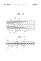
- FIG. 1 shows a first embodiment of a sensing element having a strip-shaped configuration
- FIG. 2 shows a second embodiment of a sensing element having a strip-shaped configuration
- FIG. 3 shows a third embodiment of a sensing element having a strip-shaped configuration
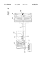
- FIG. 4 is a schematic view of a sensing device for sensing the advance movement of an airbag during deployment as an embodiment of the invention.
- FIG. 4 shows schematically an embodiment of a sensing device for sensing the movement of the front part of an airbag 4 during deployment.
- the "front part" of an airbag is understood to be the portion of the airbag that is presented for contact with a vehicle occupant when the airbag is inflated and deployed.
- the airbag 4 is located in a known manner in a receiving compartment 11.
- the airbag 4 is preferably designed as a passenger side airbag.
- the receiving compartment for the folded airbag is arranged at a suitable location in, or beneath, the instrument panel.
- a plurality of sensing elements which are designed as strips 1, are connected to the part of the airbag 4 which forms the front part when the airbag is inflated and deployed.
- the strips can be formed of plastic film.
- the strips 1 are connected to the front part of the airbag 4 at several connecting points. In the resting state, the major part of the strip to be sensed in each case is located in a strip store 12. Three strips are provided in the embodiment illustrated. The number of strips and their respective connecting points on the airbag can be selected according to the airbag and/or type of vehicle.
- FIGS. 1, 2 and 3 Electrical connections are provided on the strip. In the embodiment shown in FIGS. 1 and 2, these electrical connections are formed by electrical conductor tracks 2.
- the individual conductor tracks for example on laminated copper conductor tracks, extend on either side of the longitudinal center of the strip parallel to the lateral edges of the strip 1.
- Each conductor track is formed by two conductor portions 15 extending parallel to the longitudinal edges of the strip.
- the conductor portions possess contact regions 16 at their ends. These contact regions are located at one end 17 of the strip.
- the connecting points with the front part of the airbag 4 are located at the other end 18 of the strip (FIG. 4).
- the respective conductor portions 15 extending substantially parallel to the longitudinal direction of the strip are connected to one another by conductor portions 7 extending transversely to the longitudinal direction of the strip.
- the conductor portions of the various conductor tracks 2 are arranged in succession as viewed in the longitudinal direction of the strip and are equidistant from one another.
- the front part of the airbag in FIG. 4 moves into the interior of the vehicle.
- the strip 1 is thereby extended, the strip being separated substantially in its longitudinal center by means of a cutting edge 5.
- the term, "extend” and “extended” are understood to have their common meaning of stretching or straightening out.
- the conductor portions 7 extending transversely to the strip direction are thereby also separated.
- the separation of a respective conductor portion 7 is determined by an evaluating device 13 connected to the contact regions 16.
- the number and timing of successive separation processes can be detected by the evaluating and control device 13.
- the evaluating and control device can detect the extracted length by the number of successive separation processes.
- the speed of extraction and therefore deployment of the airbag 4 can be determined by the time intervals between the individual separation processes.
- the inflation of the airbag can then be controlled as a function thereof, as known from DE 196 11 384 or EP 0 812 741 A1.
- triangular recesses 9 are formed in the strip material, for example by punching, along the longitudinal center line of the strip 1. The guidance of the cutting edge 5, which can be provided on a stationary blade, is thus improved.
- individual resistances 3 that are interconnected in parallel are provided on the strip 1 as electrical connections.
- the individual resistances 3 are formed by a resistance layer strip that extends along the center of the strip 1 and is divided into the various individual resistances 3 by the triangular recesses 9.
- one strip end 18 is connected to the front part of the airbag 4 and the other strip end 17 also possesses contact regions for two longitudinally guided conductor tracks 19 on which the individual resistances 3 are connected in parallel via conductor portions 8.
- the two conductor tracks 19 are connected to the evaluating and control device 13 in the region of the strip end 17 (FIG. 4).
- the resistance layer track is divided into the individual resistances with respectively equal resistance values by the recesses 9. For example, 45 individual resistances can be provided.
- resistances are separated from the parallel circuit as the length of advance increases, so that a changing total resistance of the parallel circuit is produced as a function of the length of advance of the airbag 4. This changing resistance value is evaluated in the evaluating and control device 13 and is converted into corresponding control or adjustment of the inflation volume of the airbag.
- the extension the strip 1 is stopped or decelerated and a corresponding adjustment of the airbag deployment process, for example valve control, is initiated.
- a material which can be accommodated in a stackable, rollable or other manner in an identical storage volume in the strip store 12 is used for the strip 1.
- the strip preferably comprises of a plastic film having adequate flexibility.
- a guide system 6 for the strip is located between the strip store 12 and the cutting edge 5.
- This guide means can comprise a substrate against which the strip is pressed by means of a leaf spring 10.
- the contact pressure can be adjusted by means of an adjusting screw 14.
- a corresponding plug connector strip or plug contacts can be provided for connecting the electrical conductor strips 2 or the parallel circuit of the resistances 3 to the evaluating device 13.
- the kinematic reversal can also be used, during which the strip is held stationary by the electrical connections and the cutting edge 5 is extended with the airbag 4 during the inflation thereof.
Abstract
Description
Claims (20)
Applications Claiming Priority (2)
| Application Number | Priority Date | Filing Date | Title |
|---|---|---|---|
| DE29811733U | 1998-07-01 | ||
| DE29811733U DE29811733U1 (en) | 1998-07-01 | 1998-07-01 | Scanning device for scanning an airbag advance |
Publications (1)
| Publication Number | Publication Date |
|---|---|
| US6129379A true US6129379A (en) | 2000-10-10 |
Family
ID=8059288
Family Applications (1)
| Application Number | Title | Priority Date | Filing Date |
|---|---|---|---|
| US09/335,133 Expired - Fee Related US6129379A (en) | 1998-07-01 | 1999-06-17 | Device for sensing movement of an airbag |
Country Status (3)
| Country | Link |
|---|---|
| US (1) | US6129379A (en) |
| DE (1) | DE29811733U1 (en) |
| GB (1) | GB2339046B (en) |
Cited By (22)
| Publication number | Priority date | Publication date | Assignee | Title |
|---|---|---|---|---|
| US6250677B1 (en) * | 1999-02-12 | 2001-06-26 | Takata Corporation | Airbag device with position adjusting mechanism |
| US20030052479A1 (en) * | 2001-09-14 | 2003-03-20 | Martin Specht | Airbag system for a motor vehicle |
| US20030130441A1 (en) * | 2001-12-19 | 2003-07-10 | Kukdo Chemical Co., Ltd. | Powder coating composition containing low temperature curable epoxy resin |
| WO2003091665A1 (en) * | 2002-04-25 | 2003-11-06 | W.E.T. Automotive Systems Ag | Cable equipped with a functional element |
| WO2004041600A1 (en) | 2002-10-31 | 2004-05-21 | Key Safety Systems, Inc. | Variable time venting algorithm |
| WO2004050433A1 (en) * | 2002-12-04 | 2004-06-17 | Scientific Generics Limited | Sensing apparatus and method |
| US20040155445A1 (en) * | 2003-02-06 | 2004-08-12 | Husby Harald Snorre | Airbag deployment rate sensor with spool brake |
| US20040174156A1 (en) * | 2003-03-07 | 2004-09-09 | Pettypiece Robert P. | Airbag deployment monitor and sensing electronics |
| US6789819B1 (en) | 2003-03-20 | 2004-09-14 | Key Safety Systems, Inc. | Sensor for monitoring airbag deployment |
| US20040178615A1 (en) * | 2003-03-13 | 2004-09-16 | Stefan Florsheimer | Airbag deployment monitoring apparatus |
| US20040208628A1 (en) * | 2002-08-22 | 2004-10-21 | Arie Shahar | Generating of high rate modulated pulse streams |
| US20040222622A1 (en) * | 2003-05-09 | 2004-11-11 | Brian Ford | Method of folding an airbag containing sensor tapes integrated within the airbag |
| US6840539B2 (en) | 2003-02-21 | 2005-01-11 | Key Safety Systems, Inc. | Airbag and a deployment sensor |
| US6871874B2 (en) | 2002-12-18 | 2005-03-29 | Key Safety Systems, Inc. | Airbag deployment velocity sensor |
| US20050263991A1 (en) * | 2004-05-26 | 2005-12-01 | John Fisher | Airbag deployment rate sensor with electrostatic dissipative guide slots |
| US20060175817A1 (en) * | 2005-02-09 | 2006-08-10 | White Craig W | Airbag deployment rate and airbag door sensor system |
| US20060226637A1 (en) * | 2005-04-06 | 2006-10-12 | Ford Global Technologies, Llc | Airbag deployment monitoring system |
| US20070096446A1 (en) * | 1995-06-07 | 2007-05-03 | Automotive Technologies International, Inc. | Airbag Deployment Control Based on Contact with Occupant |
| EP1781505A2 (en) * | 2004-08-05 | 2007-05-09 | Key Safety Systems, Inc. | Airbag with tear seam and deployment rate sensors |
| US20070132219A1 (en) * | 1995-06-07 | 2007-06-14 | Automotive Technologies International, Inc. | Airbag inflation control based on sensed contact with occupant |
| US20080042409A1 (en) * | 1995-06-07 | 2008-02-21 | Automotive Technologies International, Inc. | Airbag Deployment Control Using Seatbelt-Mounted Sensor |
| US8820782B2 (en) | 1995-06-07 | 2014-09-02 | American Vehicular Sciences Llc | Arrangement for sensing weight of an occupying item in vehicular seat |
Families Citing this family (1)
| Publication number | Priority date | Publication date | Assignee | Title |
|---|---|---|---|---|
| DE202006011914U1 (en) * | 2006-08-03 | 2006-12-14 | Trw Automotive Safety Systems Gmbh | Airbag, to restrain a vehicle occupant on an impact collision, has an inner catch ribbon coupled to a control with a pressure adjustment valve to set the bag pressure according to the situation |
Citations (6)
| Publication number | Priority date | Publication date | Assignee | Title |
|---|---|---|---|---|
| US5246250A (en) * | 1992-11-25 | 1993-09-21 | General Motors Corporation | Air bag valve assembly |
| DE19611384A1 (en) * | 1996-03-22 | 1997-09-25 | Hs Tech & Design | Airbag system for motor vehicle |
| EP0812741A1 (en) * | 1996-03-22 | 1997-12-17 | HS Technik und Design Technische Entwicklungen GmbH | Air bag device in a motor vehicle |
| EP0836971A1 (en) * | 1996-08-22 | 1998-04-22 | Volkswagen Aktiengesellschaft | Occupant protecting arrangment for a vehicle |
| US5762367A (en) * | 1997-04-10 | 1998-06-09 | General Motors Corporation | Air bag module with inflation control device |
| GB2329058A (en) * | 1997-03-07 | 1999-03-10 | Automotive Systems Lab | Electric field sensing air bag danger-zone sensor |
-
1998
- 1998-07-01 DE DE29811733U patent/DE29811733U1/en not_active Expired - Lifetime
-
1999
- 1999-06-15 GB GB9913735A patent/GB2339046B/en not_active Expired - Fee Related
- 1999-06-17 US US09/335,133 patent/US6129379A/en not_active Expired - Fee Related
Patent Citations (7)
| Publication number | Priority date | Publication date | Assignee | Title |
|---|---|---|---|---|
| US5246250A (en) * | 1992-11-25 | 1993-09-21 | General Motors Corporation | Air bag valve assembly |
| DE19611384A1 (en) * | 1996-03-22 | 1997-09-25 | Hs Tech & Design | Airbag system for motor vehicle |
| EP0812741A1 (en) * | 1996-03-22 | 1997-12-17 | HS Technik und Design Technische Entwicklungen GmbH | Air bag device in a motor vehicle |
| EP0836971A1 (en) * | 1996-08-22 | 1998-04-22 | Volkswagen Aktiengesellschaft | Occupant protecting arrangment for a vehicle |
| US5957490A (en) * | 1996-08-22 | 1999-09-28 | Volkswagen Ag | Arrangement for protection of a vehicle occupant |
| GB2329058A (en) * | 1997-03-07 | 1999-03-10 | Automotive Systems Lab | Electric field sensing air bag danger-zone sensor |
| US5762367A (en) * | 1997-04-10 | 1998-06-09 | General Motors Corporation | Air bag module with inflation control device |
Cited By (53)
| Publication number | Priority date | Publication date | Assignee | Title |
|---|---|---|---|---|
| US8820782B2 (en) | 1995-06-07 | 2014-09-02 | American Vehicular Sciences Llc | Arrangement for sensing weight of an occupying item in vehicular seat |
| US20070096446A1 (en) * | 1995-06-07 | 2007-05-03 | Automotive Technologies International, Inc. | Airbag Deployment Control Based on Contact with Occupant |
| US20070132219A1 (en) * | 1995-06-07 | 2007-06-14 | Automotive Technologies International, Inc. | Airbag inflation control based on sensed contact with occupant |
| US20080042409A1 (en) * | 1995-06-07 | 2008-02-21 | Automotive Technologies International, Inc. | Airbag Deployment Control Using Seatbelt-Mounted Sensor |
| US7575248B2 (en) * | 1995-06-07 | 2009-08-18 | Automotive Technologies International, Inc. | Airbag inflation control based on sensed contact with occupant |
| US7712777B2 (en) | 1995-06-07 | 2010-05-11 | Automotive Technologies International, Inc. | Airbag deployment control based on contact with occupant |
| US7988190B2 (en) | 1995-06-07 | 2011-08-02 | Automotive Technologies International, Inc. | Airbag deployment control using seatbelt-mounted sensor |
| US6250677B1 (en) * | 1999-02-12 | 2001-06-26 | Takata Corporation | Airbag device with position adjusting mechanism |
| US6736424B2 (en) * | 2001-09-14 | 2004-05-18 | Breed Automotive Technology, Inc. | Airbag system for a motor vehicle |
| EP1293392A3 (en) * | 2001-09-14 | 2006-10-04 | Key Safety Systems, Inc. | Airbag device for a motor vehicle |
| US20030052479A1 (en) * | 2001-09-14 | 2003-03-20 | Martin Specht | Airbag system for a motor vehicle |
| US20030130441A1 (en) * | 2001-12-19 | 2003-07-10 | Kukdo Chemical Co., Ltd. | Powder coating composition containing low temperature curable epoxy resin |
| WO2003091665A1 (en) * | 2002-04-25 | 2003-11-06 | W.E.T. Automotive Systems Ag | Cable equipped with a functional element |
| US20040208628A1 (en) * | 2002-08-22 | 2004-10-21 | Arie Shahar | Generating of high rate modulated pulse streams |
| US6789818B2 (en) | 2002-10-31 | 2004-09-14 | Key Safety Systems, Inc. | Variable time venting algorithm |
| US6929283B2 (en) | 2002-10-31 | 2005-08-16 | Key Safety Systems, Inc. | Variable time venting algorithm |
| US20040232673A1 (en) * | 2002-10-31 | 2004-11-25 | Tony Gioutsos | Variable time venting algorithm |
| WO2004041600A1 (en) | 2002-10-31 | 2004-05-21 | Key Safety Systems, Inc. | Variable time venting algorithm |
| CN1310784C (en) * | 2002-10-31 | 2007-04-18 | 关键安全体系股份有限公司 | Variable time venting algorithm |
| WO2004050433A1 (en) * | 2002-12-04 | 2004-06-17 | Scientific Generics Limited | Sensing apparatus and method |
| US6871874B2 (en) | 2002-12-18 | 2005-03-29 | Key Safety Systems, Inc. | Airbag deployment velocity sensor |
| US6793243B2 (en) | 2003-02-06 | 2004-09-21 | Key Safety Systems, Inc. | Airbag deployment rate sensor with spool brake |
| US20040155445A1 (en) * | 2003-02-06 | 2004-08-12 | Husby Harald Snorre | Airbag deployment rate sensor with spool brake |
| US6840539B2 (en) | 2003-02-21 | 2005-01-11 | Key Safety Systems, Inc. | Airbag and a deployment sensor |
| WO2004081580A1 (en) * | 2003-03-07 | 2004-09-23 | Key Safety Systems, Inc. | Airbag deployment monitor and sensing electronics |
| CN100392407C (en) * | 2003-03-07 | 2008-06-04 | 关键安全体系股份有限公司 | Airbag deployment monitor and sensing electronic circuitry |
| US6894483B2 (en) | 2003-03-07 | 2005-05-17 | Key Safety Systems, Inc. | Airbag deployment monitor and sensing electronics |
| US20040251892A1 (en) * | 2003-03-07 | 2004-12-16 | Pettypiece Robert P. | Airbag deployment monitor and sensing electronics |
| US20040174156A1 (en) * | 2003-03-07 | 2004-09-09 | Pettypiece Robert P. | Airbag deployment monitor and sensing electronics |
| US6838870B2 (en) | 2003-03-07 | 2005-01-04 | Key Safety Systems, Inc. | Airbag deployment monitor and sensing electronics |
| WO2004081582A1 (en) * | 2003-03-07 | 2004-09-23 | Key Safety Systems, Inc. | Airbag deployment monitor and sensing electronics |
| US20040207261A1 (en) * | 2003-03-07 | 2004-10-21 | Pettypiece Robert P. | Airbag deployment monitor and sensing electronics |
| KR100681171B1 (en) | 2003-03-07 | 2007-02-12 | 키 세이프티 시스템즈 인코포레이티드 | Airbag deployment monitor and sensing electronics |
| KR100681109B1 (en) * | 2003-03-07 | 2007-02-08 | 키 세이프티 시스템즈 인코포레이티드 | Airbag deployment monitor and sensing electronics |
| US7081692B2 (en) | 2003-03-07 | 2006-07-25 | Key Safety Systems, Inc. | Airbag deployment monitor and sensing electronics |
| US6825654B2 (en) | 2003-03-07 | 2004-11-30 | Key Safety Systems, Inc. | Airbag deployment monitor and sensing electronics |
| WO2004083005A1 (en) * | 2003-03-13 | 2004-09-30 | Key Safety Systems, Inc. | Airbag deployment monitoring apparatus |
| US20040178615A1 (en) * | 2003-03-13 | 2004-09-16 | Stefan Florsheimer | Airbag deployment monitoring apparatus |
| US7147245B2 (en) | 2003-03-13 | 2006-12-12 | Key Safety Systems, Inc. | Airbag deployment monitoring apparatus |
| EP1603777A4 (en) * | 2003-03-20 | 2006-06-21 | Key Safety Systems Inc | Device for monitoring airbag deployment |
| US20040183289A1 (en) * | 2003-03-20 | 2004-09-23 | Husby Harald S. | Sensor for monitoring airbag deployment |
| EP1603777A1 (en) * | 2003-03-20 | 2005-12-14 | Key Safety Systems, Inc. | Device for monitoring airbag deployment |
| US6789819B1 (en) | 2003-03-20 | 2004-09-14 | Key Safety Systems, Inc. | Sensor for monitoring airbag deployment |
| US20040222622A1 (en) * | 2003-05-09 | 2004-11-11 | Brian Ford | Method of folding an airbag containing sensor tapes integrated within the airbag |
| US6951532B2 (en) | 2003-05-09 | 2005-10-04 | Key Safety Systems, Inc. | Method of folding an airbag containing sensor tapes integrated within the airbag |
| WO2005118357A1 (en) * | 2004-05-26 | 2005-12-15 | Key Safety Systems, Inc. | Airbag deployment rate sensor with electrostatic dissipative guide slots |
| US7070203B2 (en) | 2004-05-26 | 2006-07-04 | Key Safety Systems, Inc. | Airbag deployment rate sensor with electrostatic dissipative guide slots |
| US20050263991A1 (en) * | 2004-05-26 | 2005-12-01 | John Fisher | Airbag deployment rate sensor with electrostatic dissipative guide slots |
| EP1781505A2 (en) * | 2004-08-05 | 2007-05-09 | Key Safety Systems, Inc. | Airbag with tear seam and deployment rate sensors |
| EP1781505A4 (en) * | 2004-08-05 | 2009-11-25 | Key Safety Systems Inc | Airbag with tear seam and deployment rate sensors |
| US20060175817A1 (en) * | 2005-02-09 | 2006-08-10 | White Craig W | Airbag deployment rate and airbag door sensor system |
| US20060226637A1 (en) * | 2005-04-06 | 2006-10-12 | Ford Global Technologies, Llc | Airbag deployment monitoring system |
| US7568727B2 (en) * | 2005-04-06 | 2009-08-04 | Ford Global Technologies, Llc | Airbag deployment monitoring system |
Also Published As
| Publication number | Publication date |
|---|---|
| GB9913735D0 (en) | 1999-08-11 |
| GB2339046B (en) | 2000-06-14 |
| DE29811733U1 (en) | 1999-07-22 |
| GB2339046A (en) | 2000-01-12 |
Similar Documents
| Publication | Publication Date | Title |
|---|---|---|
| US6129379A (en) | Device for sensing movement of an airbag | |
| US6552550B2 (en) | Vehicle occupant proximity sensor | |
| DE4406897C1 (en) | Arrangement for detecting occupation of motor vehicle seats | |
| DE60010878T2 (en) | AIRBAG COVER WITH DRIVER POSITION SENSOR AND HORN SWITCH | |
| EP1580080B1 (en) | Seating sensor having film switch and resistor element | |
| US5005861A (en) | Velocity change sensor with double pole sensor | |
| US6932382B2 (en) | Hall effect sensor assembly | |
| US8346440B2 (en) | Occupant detection system and method of controlling the system | |
| DE102019208080A1 (en) | AIRBAGE DEVICE FOR VEHICLE | |
| CN1086839C (en) | Force-responsive detectors and systems | |
| US6945560B2 (en) | Airbag device for a vehicle | |
| DE4130897C2 (en) | Accelerometer in a passenger restraint system | |
| EP1961608A1 (en) | Vehicle seat | |
| CN211765401U (en) | Curtain airbag for vehicle | |
| EP0996557B1 (en) | Capacitive sensing in vehicles | |
| EP1683684A1 (en) | Checkable seat occupancy sensor | |
| WO1998029889A1 (en) | Electro-mechanical accelerometer | |
| WO2020167775A1 (en) | Connector-integrated grounding systems and methods | |
| DE10001086A1 (en) | Air bag system producing field measured during deployment, to control inflation safely, includes control unit located inside air bag | |
| GB2236621A (en) | Velocity change sensors | |
| US11167711B2 (en) | Airbag deployment data collection | |
| US7422440B2 (en) | Method and apparatus for determining a position of a location dependent device | |
| ITTO970601A1 (en) | CONTROL SYSTEM OF THE ACTIVATION OF AN AIR-BAG ON BOARD A CAR VEHICLE. | |
| DE4231873A1 (en) | SECURING SPEED CHANGE SENSOR | |
| EP0947398A2 (en) | Method and apparatus for inflating an airbag with seat position recognizing means |
Legal Events
| Date | Code | Title | Description |
|---|---|---|---|
| AS | Assignment |
Owner name: BREED AUTOMOTIVE TECHNOLOGY, INC., FLORIDA Free format text: ASSIGNMENT OF ASSIGNORS INTEREST;ASSIGNOR:SPECHT, MARTIN;REEL/FRAME:010047/0881 Effective date: 19990611 |
|
| AS | Assignment |
Owner name: CONGRESS FINANCIAL CORPORATION (FLORIDA), FLORIDA Free format text: SECURITY INTEREST;ASSIGNOR:BREED AUTOMOTIVE TECHNOLOGY, INC.;REEL/FRAME:011442/0646 Effective date: 20001226 |
|
| AS | Assignment |
Owner name: BREED AUTOMOTIVE TECHNOLOGY, INC., MICHIGAN Free format text: RELEASE OF SECURITY INTEREST IN TRADEMARKS;ASSIGNOR:CONGRESS FINANCIAL CORPORATION;REEL/FRAME:014313/0243 Effective date: 20030725 |
|
| AS | Assignment |
Owner name: CITICORP USA, INC., AS TERM C LOAN COLLATERAL AGEN Free format text: SECURITY AGREEMENT;ASSIGNOR:BREED AUTOMOTIVE TECHNOLOGY, INC.;REEL/FRAME:014428/0283 Effective date: 20030425 |
|
| FPAY | Fee payment |
Year of fee payment: 4 |
|
| AS | Assignment |
Owner name: KEY SAFETY SYSTEMS, INC., MICHIGAN Free format text: ASSIGNMENT OF ASSIGNORS INTEREST;ASSIGNOR:BREED AUTOMOTIVE TECHNOLOGY, INC.;REEL/FRAME:015355/0863 Effective date: 20041113 |
|
| AS | Assignment |
Owner name: CITICORP USA, INC., NEW YORK Free format text: SECURITY AGREEMENT;ASSIGNORS:KEY SAFETY SYSTEMS, INC;KSS HOLDINGS, INC;KSS ACQUISITION COMPANY;AND OTHERS;REEL/FRAME:019297/0249 Effective date: 20070308 Owner name: CITICORP USA, INC.,NEW YORK Free format text: SECURITY AGREEMENT;ASSIGNORS:KEY SAFETY SYSTEMS, INC;KSS HOLDINGS, INC;KSS ACQUISITION COMPANY;AND OTHERS;REEL/FRAME:019297/0249 Effective date: 20070308 |
|
| FPAY | Fee payment |
Year of fee payment: 8 |
|
| REMI | Maintenance fee reminder mailed | ||
| LAPS | Lapse for failure to pay maintenance fees | ||
| STCH | Information on status: patent discontinuation |
Free format text: PATENT EXPIRED DUE TO NONPAYMENT OF MAINTENANCE FEES UNDER 37 CFR 1.362 |
|
| FP | Lapsed due to failure to pay maintenance fee |
Effective date: 20121010 |