US6130629A - Rate 24/25 (0,9) code method and system for PRML recording channels - Google Patents
Rate 24/25 (0,9) code method and system for PRML recording channels Download PDFInfo
- Publication number
- US6130629A US6130629A US09/205,319 US20531998A US6130629A US 6130629 A US6130629 A US 6130629A US 20531998 A US20531998 A US 20531998A US 6130629 A US6130629 A US 6130629A
- Authority
- US
- United States
- Prior art keywords
- codeword
- bits
- bit
- pivot
- code
- Prior art date
- Legal status (The legal status is an assumption and is not a legal conclusion. Google has not performed a legal analysis and makes no representation as to the accuracy of the status listed.)
- Expired - Lifetime
Links
Images
Classifications
-
- H—ELECTRICITY
- H04—ELECTRIC COMMUNICATION TECHNIQUE
- H04L—TRANSMISSION OF DIGITAL INFORMATION, e.g. TELEGRAPHIC COMMUNICATION
- H04L1/00—Arrangements for detecting or preventing errors in the information received
- H04L1/004—Arrangements for detecting or preventing errors in the information received by using forward error control
- H04L1/0056—Systems characterized by the type of code used
- H04L1/0057—Block codes
-
- G—PHYSICS
- G11—INFORMATION STORAGE
- G11B—INFORMATION STORAGE BASED ON RELATIVE MOVEMENT BETWEEN RECORD CARRIER AND TRANSDUCER
- G11B20/00—Signal processing not specific to the method of recording or reproducing; Circuits therefor
- G11B20/10—Digital recording or reproducing
- G11B20/14—Digital recording or reproducing using self-clocking codes
- G11B20/1403—Digital recording or reproducing using self-clocking codes characterised by the use of two levels
- G11B20/1423—Code representation depending on subsequent bits, e.g. delay modulation, double density code, Miller code
- G11B20/1426—Code representation depending on subsequent bits, e.g. delay modulation, double density code, Miller code conversion to or from block codes or representations thereof
-
- H—ELECTRICITY
- H04—ELECTRIC COMMUNICATION TECHNIQUE
- H04L—TRANSMISSION OF DIGITAL INFORMATION, e.g. TELEGRAPHIC COMMUNICATION
- H04L1/00—Arrangements for detecting or preventing errors in the information received
- H04L1/004—Arrangements for detecting or preventing errors in the information received by using forward error control
- H04L1/0041—Arrangements at the transmitter end
-
- H—ELECTRICITY
- H04—ELECTRIC COMMUNICATION TECHNIQUE
- H04L—TRANSMISSION OF DIGITAL INFORMATION, e.g. TELEGRAPHIC COMMUNICATION
- H04L1/00—Arrangements for detecting or preventing errors in the information received
- H04L1/004—Arrangements for detecting or preventing errors in the information received by using forward error control
- H04L1/0045—Arrangements at the receiver end
-
- G—PHYSICS
- G11—INFORMATION STORAGE
- G11B—INFORMATION STORAGE BASED ON RELATIVE MOVEMENT BETWEEN RECORD CARRIER AND TRANSDUCER
- G11B20/00—Signal processing not specific to the method of recording or reproducing; Circuits therefor
- G11B20/10—Digital recording or reproducing
- G11B20/14—Digital recording or reproducing using self-clocking codes
- G11B20/1403—Digital recording or reproducing using self-clocking codes characterised by the use of two levels
- G11B20/1423—Code representation depending on subsequent bits, e.g. delay modulation, double density code, Miller code
- G11B20/1426—Code representation depending on subsequent bits, e.g. delay modulation, double density code, Miller code conversion to or from block codes or representations thereof
- G11B2020/1434—8 to 9 modulation
-
- G—PHYSICS
- G11—INFORMATION STORAGE
- G11B—INFORMATION STORAGE BASED ON RELATIVE MOVEMENT BETWEEN RECORD CARRIER AND TRANSDUCER
- G11B20/00—Signal processing not specific to the method of recording or reproducing; Circuits therefor
- G11B20/10—Digital recording or reproducing
- G11B20/14—Digital recording or reproducing using self-clocking codes
- G11B20/1403—Digital recording or reproducing using self-clocking codes characterised by the use of two levels
- G11B20/1423—Code representation depending on subsequent bits, e.g. delay modulation, double density code, Miller code
- G11B20/1426—Code representation depending on subsequent bits, e.g. delay modulation, double density code, Miller code conversion to or from block codes or representations thereof
- G11B2020/1446—16 to 17 modulation
-
- G—PHYSICS
- G11—INFORMATION STORAGE
- G11B—INFORMATION STORAGE BASED ON RELATIVE MOVEMENT BETWEEN RECORD CARRIER AND TRANSDUCER
- G11B20/00—Signal processing not specific to the method of recording or reproducing; Circuits therefor
- G11B20/10—Digital recording or reproducing
- G11B20/14—Digital recording or reproducing using self-clocking codes
- G11B20/1403—Digital recording or reproducing using self-clocking codes characterised by the use of two levels
- G11B20/1423—Code representation depending on subsequent bits, e.g. delay modulation, double density code, Miller code
- G11B20/1426—Code representation depending on subsequent bits, e.g. delay modulation, double density code, Miller code conversion to or from block codes or representations thereof
- G11B2020/1449—24 to 25 modulation
Definitions
- the present invention relates in general to codes for modulation encoding and decoding systems, and, more particularly, to a system employing a 24/25 (0,9) modulation code.
- Many conventional magnetic recording systems include partial response or peak-detection magnetic recording channels for data detection.
- Data detection within a digital communication channel is generally based on periodically sampling the amplitude of the transmitted signal.
- Enhancements to encoding techniques extend the performance of partial response and peak detection systems by allowing more transitions without degrading data detection.
- Modulation codes may be employed to achieve high transition densities within magnetic recording systems. High transition densities allow more frequent timing and gain control updates, which, in turn, result in a lower required channel input signal to noise ratio (SNR) for a given magnetic recording channel performance.
- SNR channel input signal to noise ratio
- data are first encoded with an error correction code, and then encoded with a modulation code using a modulation encoder and precoder before the encoded data are written to a recording channel of a magnetic recording media, such as disk or tape.
- an equalizer equalizes the readback signal to a target partial response (PR).
- PR target partial response
- the equalized signal may then be applied to a maximum likelihood (ML) sequence detector, also known as a Viterbi detector, to reconstruct the modulation-coded encoded data signal.
- ML maximum likelihood
- the reconstructed signal may then be subject to inverse coding operations, such as unprecoding, modulation decoding, and then error correction decoding.
- the modulation encoder and precoder are employed to provide that timing recovery circuitry and gain control circuitry as used with the equalizer receive non-zero or other active information frequently, without degrading the efficacy of the ML sequence detector to correctly detect the sequence for a given PR.
- the modulation encoder receives a group of M bits and encodes the M bits as a group of N channel bits such that the group of N channel bits satisfy a given constraint.
- the modulation code should be a block code where no a priori knowledge of bits or other bit group information outside the given group of M bits and N bits is required.
- the code should have a high rate or coding density of M/N, and third, the code should have good constraints.
- Fourth, the code should be efficiently implemented in a logic circuit, and fifth, the code should not affect the efficacy of the ML sequence detector.
- Run length limited (RLL) block codes may be typically used for the modulation code, and these RLL block codes may be characterized by the coding density of M/N, where M is an integer, which is usually either a multiple or submultiple of the number 8, and N is a larger integer than M.
- M data bits are coded into N symbols, or channel bits, with the constraint that M be a multiple or submultiple of 8 arising from the outer, error correcting code working on a byte by byte basis. Decoding a block of channel bits which contains one or more errors contaminates an entire block; accordingly, alignment of block boundaries with byte boundaries reduces the number of contaminated bytes.
- RLL block codes are also characterized by run length constraints, labeled as (d,G/I), where d is the minimum number of zeros between ones, G is the maximum number of zeros, between ones, and I is the maximum number of zeros between ones in odd/even substrings.
- d the minimum number of zeros between ones
- G the maximum number of zeros
- I the maximum number of zeros between ones in odd/even substrings.
- the I constraint is generally only useful for some PR channels, an example of which is a channel with a partial response transfer function of the form 1-D 2 , also known as a PR4 channel.
- Other PR channels may be used; for example; an EPR4 channel, which is characterized by the channel's partial response transfer function, or polynomial, being 1+D-D 2 -D 3 , may be used.
- the G constraint itself, in conjunction with a 1/(1 ⁇ D 2 ) precoder, provides sufficient timing and/or gain control information while limiting the quasi-catastrophic sequences.
- PRML magnetic read channels of the prior art have employed a popular 8/9 code with constraints (0,4,4), such as is described in U.S. Pat. No.
- the present invention relates to encoding or decoding employing a 24/25 (0,9) codeword formed from three bytes of binary data.
- An exemplary embodiment encodes by storing the first and second bytes as first and second bit strings and the third byte as first and second nibbles.
- the encoder determines whether each of the first and second bit strings contains at least one code violation, each code violation corresponding to a given bit sequence, and identifies a type and a position of the code violation.
- a pivot bit is inserted between the first and second strings.
- the first and second strings with the pivot bit inserted therebetween is encoded into a 16/17 (0,5) codeword based on the type and the position of each code violation identified by the processor.
- Encoding into a 16/17(0,5) word corrects, as necessary, any code violation in the first and second bit strings by 1) setting the inserted pivot bit to a first value, 2) defining values for a bit in each of the first and second bit strings as additional pivot bits, the additional pivot bits identifying the type and the position of each code violation, 3) preserving values for bits not included in the given bit sequence corresponding to the code violation, and 4) assigning values, as necessary, for one or more bits of the given bit sequence.
- the 24/25 (0,9) codeword is produced by inserting the first and second nibbles of the third byte adjacent to the additional pivot bits of the first and second bit strings in the 16/17 (0,5) codeword, respectively.
- Another exemplary embodiment decodes by dividing the 24/25 (0,9) codeword into first and second nibbles and a 16/17 (0,5) codeword based on a set of pivot bits of the 24/25 (0,9) codeword, the first and second nibbles forming the third byte.
- the 16/17 (0,5) codeword is stored as N symbols; and preserved bits are provided from the N symbols of the 16/17 (0,5) codeword based on the set of pivot bits.
- Whether the first and second bytes include a code violation is determined from the set of pivot bits that identify a type and a position of any code violation in the first and second bytes. Each code violation corresponds to a given bit sequence within the first and second bytes.
- the first and second bytes are formed from the preserved bits and the given bit sequence of each code violation in accordance with the set of pivot bits, wherein any code violation in the first and second bytes is reconstructed as the given bit sequence having the type and at the position as defined by the set of pivot bits.
- the preserved bits are assigned to respective locations in the first and second bytes in accordance with the set of pivot bits.
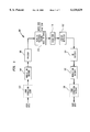
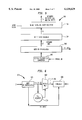
- FIG. 1 is a block diagram showing a system having a modulation encoder and a modulation decoder employing a rate 24/25 (0,9) code in accordance with an exemplary embodiment of the present invention
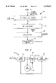
- FIG. 2 is a block diagram showing a modulation encoder in accordance with an exemplary embodiment of the present invention
- FIG. 3 is a block diagram of a 24/25 (0,9) block encoder incorporating a 16/17 (0,5) block encoder having a minimized encoding equation set in accordance with an exemplary embodiment of the present invention
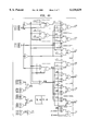
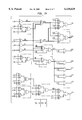
- FIG. 4A is a first half of a 16/17 (0,5) block encoder circuit implementing a minimized encoding equation set in accordance with an exemplary embodiment of the present invention
- FIG. 4B is a second half of a 16/17 (0,5) block encoder circuit implementing a minimized encoding equation set in accordance with an exemplary embodiment of the present invention
- FIG. 5 is a block diagram showing a modulation decoder in accordance with an exemplary embodiment of the present invention.
- FIG. 6 is a block diagram of a 24/25 (0,9) block decoder incorporating a 16/17 (0,5) block decoder having a minimized decoding equation set in accordance with an exemplary embodiment of the present invention
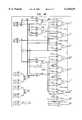
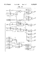
- FIG. 7A is a first half of a 16/17 (0,5) block decoder circuit implementing a minimized decoding equation set in accordance with an exemplary embodiment of the present invention.
- FIG. 7B is a second half of a 16/17 (0,5) block decoder circuit implementing a minimized decoding equation set in accordance with an exemplary embodiment of the present invention.
- the present invention relates to a system and method employing a rate 24/25 (0,9) code constructed in accordance with a set of pivot bits and a set of corrections for predefined code violations which, for the exemplary embodiments as described below, limits the number of consecutive zeros seen by a channel to nine, thereby resulting in a G constraint of nine.
- the constructed code includes a high transition density which allows for more frequent timing and gain control updates, which results in lower required channel input signal to noise ratio for a given channel performance.
- FIG. 1 is a block diagram showing a modulation encoder and a modulation decoder system 100 employing a rate 24/25 (0,9) code in accordance with an exemplary embodiment of the present invention.
- the system 100 includes an encoding section having an optional error correction coder 102, modulation encoder 104, and precoder 106.
- the system 100 also includes a decoding section including an equalizer 110, sequence detector 112, unprecoder 114, modulation decoder 116 and optional error correction decoder 118.
- Coded information from the encoding section is written to a magnetic recording channel 108, which may be magnetic disk or tape media, and the coded information is read from the magnetic recording channel 108 by the decoding section.
- Optional error correction coder 102 may receive user data and encode the user data using error correction techniques as are known in the art to provide these datawords.
- the modulation encoder 104 encodes the datawords as 24/25 (0,9) output codeword Z having 25 symbols, in accordance with the present invention. These output codewords are then subject to a preceding process by precoder 106.
- the precoder 106 is used to verify that the output codewords of the modulation encoder 106 satisfy constraints of peripheral gain control and timing recovery circuits, such as an all 1's, an all 0's and/or an alternating 101010. . . sequence being encoded and recorded as different, predefined bit sequences.
- Such precoder 106 may be, for example, a precoder of the form 1/(1 ⁇ D 2 ).
- the output sequence of the precoder 106 is then written to the magnetic recording channel 108 using, for example, a recording head, and then read from the magnetic recording channel 108 by a device such as, for example, a read-back head.
- the received signal is then equalized within equalizer 110 such that the equalized signal corresponds to the partial response transfer function, (e.g., EPR4 transfer function) which also represents a output channel response polynomial corresponding to the received sequence of levels.
- the received sequence is provided to the sequence detector 112.
- Sequence detector 112 which may be a Viterbi detector, determines a sequence of symbols in a state trellis structure that is closest to the received sequence of levels according to a predefined metric.
- the sequence detector 112 then provides the determined sequence of symbols as the output symbol sequence.
- the unprecoder 114 receives the output symbol sequences and reverses the preceding operation of the precoder 106. Unprecoder 114 then provides a sequence of output codewords (Z's) to the modulation decoder 116. Modulation decoder 116 decodes each codeword Z of rate 24/25 (0,9) in accordance with the present invention to provide a sequence of three-byte datawords. Optional error correction decoder 118 may then be used to perform error correction processing to provide reconstructed user data.
- the modulation encoder 104 and modulation decoder 116 each encode and decode, respectively, in accordance with the characteristics of the 24/25 (0,9) code construction.
- the 24/25 (0,9) code construction is based on encoding of three bytes of information, defined as the dataword A.
- the 24/25 (0,9) code construction is based on forming the codeword Z by first forming a codeword ⁇ in accordance with a 16/17 (0,5) code construction from two bytes of the dataword A, and then interleaving the third remaining byte into the 16/17 (0,5) codeword ⁇ .
- the following description of the preferred embodiment refers to three bytes of user data, the present invention is not so limited to consecutive bits within the bytes of the user data.
- the bits of the user data may be rearranged, or interleaved, so as to remove naturally occurring periodicity within the data (e.g., repeating sign bits every eighth or sixteenth bit position of the sequence). Consequently, as used herein, the term "byte" simply refers to a group of eight bits from an input sequence of user data.
- Code construction of the 16/17 (0,5) codeword is a basis for the 24/25 (0,9) code construction, and may be summarized as follows.
- a 16/17 (0,5) block encoder encodes 16 bits of the input dataword A consisting of elements a(1), . . . , a(16) (herein defined as A').
- the input dataword A' is then split into two bit strings: an 8 bit left bit string and an 8 bit right string consisting of a(1), . . . , a(8) and a(9), . . . , a(16), respectively.
- a temporary 17 bit output codeword X consisting of elements x(1), . . . , x(17) is formed.
- the middle bit of X, x(9) is defined as a pivot bit, pbm, and is set to logic "1".
- the left bit string of X, x(1), . . . , x(8) comprises the left bit string of A' while the right bit string of X, x(10), . . . , x(17) consists of the right bit string of A'.
- the bit string X is checked for pre-defined code violations. For a (0,5) code construction the bit string X should have no more than two consecutive zeroes at either end of the output bit string, or have no more than five consecutive zeroes within the bit string.
- Code violations in codeword X are classified based on whether the violation occurs in the left bit string of X or in the right bit string of X. In addition, these code violations are further classified based on where the violation occurs in the respective string. Whether one or more or combinations of these code violations exists may be determined using combinational logic equations involving the elements of A. If there are no violations in X, the bit string X is simply assigned as the output codeword ⁇ .
- the main pivot bit pbm is set to 0 to indicate that at least one code violation occurred in X.
- the pivot bits pbl and pbr indicate whether only left bit string or only a right string violation has occurred. For example, in the case of a left string violation only, pbl is set to logic 0 and pbr is set to logic 1. This choice for pivot bit logic values ensures that any modifications to the left string of X do not cause any violations in the right string. Given the above code construction decoding is easily determined by examination of the various pivot bits observed in the received codeword ⁇ . A description of the encoding and decoding processes and combinational logic equations for implementing encoding and decoding in accordance with the 16/17 (0,5) code construction are described subsequently.
- the rate 24/25 (0,9) codeword Z is then obtained by interleaving the third, and remaining, byte of dataword A with the 16/17 (0,5) codeword 4 constructed from the first two bytes of dataword A.
- the 24/25 (0,9) codeword Z is obtained by first splitting the remaining byte into two, 4-bit portions UL and UR that are the left and right nibbles of the uncoded byte. The portions UL and UR are then inserted between bit positions of the 16/17 (0,5) codeword ⁇ .
- bit string ⁇ > of the output 16/17 (0,5) codeword is given by ⁇ L pbl pbm pbr R>.
- bit string ⁇ Z> of the output 24/25 (0,9) codeword Z is defined as ⁇ L UL pbl pbm pbr UR R>.
- Encoding and combinational logic equations for implementing encoding in accordance with the 16/17 (0,5) code construction are now described. Decoding and combinational logic equations for implementing decoding are described subsequently with respect to the 24/25 (0,9) modulation decoder 116 of FIGS. 5 and 6.
- the two bytes of the dataword A are first split into two bit-strings of element values, such as, for example, a left string including dataword A' element values a(1) through a(8) and a right string including dataword A' element values a(9) through a(16).
- a temporary 17 bit output codeword X x(1), x(2), . . .
- x(17) is formed from the left and right strings by inserting a pivot bit, pbm, between the left and right strings.
- the pivot bit, pbm, corresponding to the value of element x(9) of X is initially set to, for example, a "1", forming the temporary codeword X shown in Table 1:
- the pivot bit pbm (of x(9)) is set to 0 to allow a decoder in accordance with the present invention to identify a codeword ⁇ , and so codeword Z, that contains a dataword A' having at least one violation.
- Three violation cases are possible: a first case in which violations occur only in the left string, a second case in which violations occur only in the right string, and a third case in which violations occur in both the left and right strings.
- a different operation is performed to correct the code violations.
- the pivot bit pbl is set to "0" and the pivot bit pbr is set to "1" to allow a decoder in accordance with the present invention to identify a codeword which contains a dataword A' having left string-only violations of the first case. No further modifications are made to the right string for this first case; consequently, modifications to the element values of the left string may not cause code violations to subsequently occur within the right string since pbr is set to 1. Since the pivot bits pbl and pbr are employed at the position of bits a(8) and a(9), respectively, of the input dataword A', the values of a(8) and a(9) are desirably preserved and stored in the left string.
- an encoder process corrects these violations. Since a violation at a position in the left string corresponds to zero values at that position based on the definitions of Table 2 for the exemplary embodiment, the bits corresponding to the element values for each violation at the corresponding position(s) may be set to one or zero, depending on the encoder's decision process. The remaining bits which are not known to be zero values are then desirably preserved. However, the positions of these code violations and the encoder's decision process are also known to the decoder in order to decode the codeword ⁇ . Table 3 gives a list of possible violations within the left string, and the corresponding bit element values that are desirably preserved.
- an exemplary embodiment of the present invention employs two different codewords for ⁇ , each corresponding to a respective one of these two versions of the first case of left string-only violations.
- the element z(3) of codeword ⁇ which is the pivot bit pb1a, may be employed to distinguish between the two versions.
- setting the pivot bit pb1a to a "1" indicates an l1-only code violation
- setting the pivot bit pb1a to "0" indicates all other left string-only violations.
- An exemplary codeword ⁇ is given in Table 4 for a left string-only, l1-only code violation which satisfies the conditions of Table 3, while Table 5 provides the exemplary codeword ⁇ for all other left string-only violations except the l1-only code violation:
- the output codeword ⁇ may be formed in manner employing the left-only and right-only violation corrections as given in Tables 2-8. Consequently, the codewords ⁇ for the versions of the remaining third case for the exemplary embodiment of the present invention are as given in Tables 9-12.
- the first and second classifications and identified code violations may be expressed using Boolean equations that express the bit values of the encoder output codeword ⁇ as a function of the bit values of the input dataword ⁇ .
- a "&" expression indicates a logical AND operation
- a "+” expression indicates a logical OR operation
- a "! expression indicates a logical complement.
- bit values for the output codeword elements z(1), z(2) . . . z(17) may be given for the exemplary embodiment as set forth in equations 15-31:
- FIG. 2 is a block diagram showing a block diagram of modulation encoder 104 in accordance with an exemplary embodiment of the present invention.
- the modulation encoder 104 includes a parallel shift register 202, 16/17 (0,5) block encoder 204, word interleaver 205, and parallel to serial converter 206.
- the 16/17 (0,5) block encoder 204 of FIG. 2 constructs an output codeword ⁇ from the first two bytes of the dataword A received by the modulation encoder 104.
- Datawords of three bytes are divided into a first sequence of 16 bits and a second sequence of 8 bits.
- the first sequence of 16 bits in parallel is received by shift register 202 that sequentially provides 16-bit parallel words to the 16/17 (0,5) block encoder 204 in accordance with a word clock signal.
- 16/17 (0,5) block encoder constructs 16/17 (0,5) output codeword ⁇ based on the input word.
- Each codeword ⁇ is provided as a 17-bit parallel word to the word interleaver 205.
- the word interleaver 205 divides the second sequence of 8 bits (or third byte) into two nibbles, and inserts the two nibbles into the 16/17 (0,5) output codeword ⁇ .
- the 25 parallel-bit, 24/25 (0,9) codeword Z is then converted to a serial bit stream by parallel to serial converter 206 in accordance with a symbol clock signal.
- FIG. 3 is a block diagram of a 24/25 (0,9) block encoder as shown in FIG. 2 of an exemplary embodiment having a minimized encoding equation set in accordance with the present invention.
- the input dataword A is provided to a buffer register 501 that separates the dataword into the two byte word A' and the third byte.
- the input dataword A' is provided to both an output mux 502 and a pre-encoder 504.
- Pre-encoder 504 provides intermediate variable values corresponding to the intermediate variables given in equations (1) through (14) and (32) through (39), which equations are derived from the code violations as described previously.
- output mux 502 uses the intermediate variable values, provides the output codeword ⁇ bits z(1), z(2), . . . z(17) in accordance with the minimized set of encoder equations (15') through (31'), respectively.
- Word interleaver 205 then interleaves the third byte into the codeword ⁇ to provide the codeword Z.
- FIGS. 4A and 4B are first and second halves, respectively, of a 16/17 (0,5) block encoder circuit encoding a rate 16/17 (0,5) code with a minimized encoding equation set as given by equations (15') through (31') in accordance with the exemplary embodiment of the present invention.
- the unprecoder 114 of the exemplary system 100 of FIG. 1 reverses the preceding operation of the precoder 106, and provides output codewords to the modulation decoder 116.
- the modulation decoder 116 decodes the symbol sequence in accordance with the 16/17 (0,5) code construction of the present invention to provide a sequence of datawords.
- FIG. 5 is a block diagram showing the modulation decoder 116 of FIG. 1 in accordance with an exemplary embodiment of the present invention.
- the modulation decoder includes a serial to parallel converter 302, 16/17 (0,5) block decoder 304 and parallel shift register 306.
- Codewords Z are provided as a serial symbol stream and are converted to a parallel bit stream by serial to parallel converter 302 in accordance with a symbol clock signal.
- the word de-interleaver removes the third byte from the codeword Z to provide the codeword ⁇ to the 16/17 (0,5) block decoder 304.
- the 16/17 (0,5) block decoder 304 constructs an output dataword A' corresponding to the based on the input 16/17 (0,5) codeword ⁇ .
- the 16/17 block decoder 304 provides these datawords A' of 16 bits to the shift register 306. Datawords of 16 bits in parallel are then sequentially provided by shift register 306 in accordance with a word clock signal. In a similar manner as described with respect to the modulation encoder 104, a codeword is converted to a corresponding dataword while the next codeword is received in the serial to parallel converter 302.
- the input codeword ⁇ is formed based on the absence or detected presence of one or more predefined code violations within the original dataword a.
- the modulation decoder in accordance with the exemplary embodiment of the present invention interprets the values of the pivot bits to re-constitute the bit values for elements causing the code violations defined by the pivot bits, thereby providing a 16-bit words (for the first and second bytes of dataword A) having element values from codeword ⁇ as given in the following Tables 13-21.
- Boolean equations may be formed to express the relationship between the input element values of codeword ⁇ with the output element values of the decoded dataword A'.
- a "&" expression indicates a logical AND operation
- a "+" expression indicates a logical OR operation
- a "! expression indicates a logical complement.
- FIG. 6 is a block diagram of a 24/25 (0,9) block decoder 304 as shown in FIG. 5 of an exemplary embodiment having a minimized decoding equation set in accordance with the present invention.
- Pre-decoder 604 provides intermediate variable values corresponding to the intermediate variables given in equations (40) through (43) and (60) through (81) described previously, and which are derived from the 16/17 (0,5) code construction, which construction is as described previously.
- output mux 602 uses the intermediate variable values to provide the output received dataword bits d(1), d(2), . . . d(16), corresponding to a(1) through a(16) of the two bytes (codeword A') of codeword A, in accordance with equations (44) through (59), or (44') through (59'), respectively.
- a combiner 606 receives the first and second bytes (A') from the output mux 602 and the third byte from the word de-interleaver 303, and then combines the three bytes to from the dataword A.
- FIGS. 7A and 7B are first and second halves of a 16/17 (0,5) block decoder circuit decoding a rate 16/17 (0,5) code with the minimized decoding equations (44') through (59') in accordance with the exemplary embodiment of the present invention.
- circuit elements may also be implemented in the digital domain as processing steps in a software program.
- Such software may be employed in, for example, a digital signal processor, micro-controller or general purpose computer.
Abstract
Description
                                  TABLE 1
__________________________________________________________________________
x(1)
   x(2)
      x(3)
         x(4)
            x(5)
               x(6)
                  x(7)
                     x(8)
                        x(9)
                           x(10)
                              x(11)
                                 x(12)
                                    x(13)
                                       x(14)
                                          x(15)
                                             x(16)
                                                x(17)
a(1)
   a(2)
      a(3)
         a(4)
            a(5)
               a(6)
                  a(7)
                     a(8)
                        1  a(9)
                              a(10)
                                 a(11)
                                    a(12)
                                       a(13)
                                          a(14)
                                             a(15)
                                                a(16)
__________________________________________________________________________
              TABLE 2
______________________________________
Violation
Name   Violation
______________________________________
l1     x(1), x(2) and x(3) = 0 (or equivalently, a(1), a(2) and a(3) =
       0)
l2     x(2), x(3), x(4), x(5), x(6) and x(7) = 0 (or equivalently,
       a(2), . . . a(7) = 0)
l3     x(3), x(4), x(5), x(6) x(7) and x(8) = 0 (or equivalently,
       a(3), . . . a(8) = 0)
r1     x(15), x(16) and x(17) = 0 (or equivalently, a(14), a(15) and
       a(16) = 0)
r2     x(11), x(12), x(13) x(14), x(15) and x(16) = 0 (or
       equivalently, a(10), . . . a(15) = 0)
r3     x(10), x(11), x(12), x(13) x(14) and x(15) = 0 (or
       equivalently, a(9), . . . a(14) = 0)
______________________________________
              TABLE 3
______________________________________
Violation
         Zero Bits        Bits to Preserve
______________________________________
l1 only  a(1), a(2) and a(3) = 0
                          a(4), a(5), a(6), a(7), a(8)
                          and a(9)
l2 only  a(2), a(3), a(4), a(5), a(6) and
                          a(1), a(8) and a(9)
         a(7) = 0
l3 only  a(3), a(4), a(5), a(6), a(7) and
                          a(1), a(2) and a(9)
         a(8) = 0
l1, l2   a(1), a(2), a(3), a(4), a(5),
                          a(8) and a(9)
         a(6) and a(7) = 0
l1, l3   not used (same as l1, l2 and l3
         case)
l2, l3   a(2), a(3), a(4), a(5), a(6),
                          a(1) and a(9)
         a(7), a(8) and a(9) = 0
l1, l2 and l3
         a(1), a(2), a(3), a(4), a(5),
                          a(9)
         a(6), a(7) and a(8) = 0
______________________________________
                                  TABLE 4
__________________________________________________________________________
z(1)
   z(2)
      z(3)
         z(4)
            z(5)
               z(6)
                  z(7)
                     z(8)
                        z(9)
                           z(10)
                              z(11)
                                 z(12)
                                    z(13)
                                       z(14)
                                          z(15)
                                             z(16)
                                                z(17)
a(8)
   a(9)
      1  a(4)
            a(5)
               a(6)
                  a(7)
                     0  0  1  a(10)
                                 a(11)
                                    a(12)
                                       a(13)
                                          a(14)
                                             a(15)
                                                a(16)
__________________________________________________________________________
                                  TABLE 5
__________________________________________________________________________
z(1)
   z(2)
      z(3)
         z(4)
            z(5)
               z(6)
                  z(7)
                     z(8)
                        z(9)
                           z(10)
                              z(11)
                                 z(12)
                                    z(13)
                                       z(14)
                                          z(15)
                                             z(16)
                                                z(17)
1  a(1)
      0  a(2)
            a(8)
               a(9)
                  1  0  0  1  a(10)
                                 a(11)
                                    a(12)
                                       a(13)
                                          a(14)
                                             a(15)
                                                a(16)
__________________________________________________________________________
              TABLE 6
______________________________________
Violation
         Zero Bits         Bits to Preserve
______________________________________
r1 only  a(14), a(15) and a(16) = 0
                           a(8), a(9), a(10), a(11),
                           a(12) and a(13)
r2 only  a(10), a(11), a(12), a(13), a(14)
                           a(8), a(9) and a(16)
         and a(15) = 0
r3 only  a(9), a(10), a(11), a(12), a(13)
                           a(8), a(15) and a(16)
         and a(14) = 0
r1, r2   a(10), a(11), a(12), a(13), a(14),
                           a(8) and a(9)
         a(15) and a(16) = 0
r1, r3   not used (same as r1, r2 and r3
         case)
r2, r3   a(9), a(10), a(11), a(12), a(13),
                           a(8) and a(16)
         a(14) and a(15) = 0
r1, r2 and r3
         a(9), a(10), a(11), a(12), a(13),
                           a(8)
         a(14), a(15) and a(16) = 0
______________________________________
                                  TABLE 7
__________________________________________________________________________
z(1)
   z(2)
      z(3)
         z(4)
            z(5)
               z(6)
                  z(7)
                     z(8)
                        z(9)
                           z(10)
                              z(11)
                                 z(12)
                                    z(13)
                                       z(14)
                                          z(15)
                                             z(16)
                                                z(17)
a(1)
   a(2)
      a(3)
         a(4)
            a(5)
               a(6)
                  a(7)
                     1  0  0  a(10)
                                 a(11)
                                    a(12)
                                       a(13)
                                          1  a(8)
                                                a(9)
__________________________________________________________________________
                                  TABLE 8
__________________________________________________________________________
z(1)
   z(2)
      z(3)
         z(4)
            z(5)
               z(6)
                  z(7)
                     z(8)
                        z(9)
                           z(10)
                              z(11)
                                 z(12)
                                    z(13)
                                       z(14)
                                          z(15)
                                             z(16)
                                                z(17)
a(1)
   a(2)
      a(3)
         a(4)
            a(5)
               a(6)
                  a(7)
                     1  0  0  1  a(8)
                                    a(9)
                                       a(15)
                                          0  a(16)
                                                1
__________________________________________________________________________
                                  TABLE 9
__________________________________________________________________________
z(1)
   z(2)
      z(3)
         z(4)
            z(5)
               z(6)
                  z(7)
                     z(8)
                        z(9)
                           z(10)
                              z(12)
                                 z(13)
                                    z(14)
                                       z(15)
                                          z(16)
                                             z(17)
                                                z(18)
a(8)
   a(9)
      1  a(4)
            a(5)
               a(6)
                  a(7)
                     1  0  1  a(10)
                                 a(11)
                                    a(12)
                                       a(13)
                                          1  a(8)
                                                a(9)
__________________________________________________________________________
                                  TABLE 10
__________________________________________________________________________
z(1)
   z(2)
      z(3)
         z(4)
            z(5)
               z(6)
                  z(7)
                     z(8)
                        z(9)
                           z(10)
                              z(11)
                                 z(12)
                                    z(13)
                                       z(14)
                                          z(15)
                                             z(16)
                                                z(17)
1  a(1)
      0  a(2)
            a(8)
               a(9)
                  1  1  0  1  a(10)
                                 a(11)
                                    a(12)
                                       a(13)
                                          1  a(8)
                                                a(9)
__________________________________________________________________________
                                  TABLE 11
__________________________________________________________________________
z(1)
   z(2)
      z(3)
         z(4)
            z(5)
               z(6)
                  z(7)
                     z(8)
                        z(9)
                           z(10)
                              z(11)
                                 z(12)
                                    z(13)
                                       z(14)
                                          z(15)
                                             z(16)
                                                z(17)
a(8)
   a(9)
      1  a(4)
            a(5)
               a(6)
                  a(7)
                     1  0  1  1  a(8)
                                    a(9)
                                       a(15)
                                          0  a(16)
                                                1
__________________________________________________________________________
                                  TABLE 12
__________________________________________________________________________
z(1)
   z(2)
      z(3)
         z(4)
            z(5)
               z(6)
                  z(7)
                     z(8)
                        z(9)
                           z(10)
                              z(11)
                                 z(12)
                                    z(13)
                                       z(14)
                                          z(15)
                                             z(16)
                                                z(17)
1  a(1)
      0  a(2)
            a(8)
               a(9)
                  1  1  0  1  1  a(8)
                                    a(9)
                                       a(15)
                                          0  a(16)
                                                1
__________________________________________________________________________
l1=(a(1)+a(2)+a(3))=L1 (1)
l2=(a(2)+a(3)+a(4)+a(5)+a(6)+a(7))=L2 (2)
l3=(a(3)+a(4)+a(5)+a(6)+a(7)+a(8))=L3 (3)
r1=(a(14)+a(15)+a(16))=R1 (4)
r2=(a(10)+a(11)+a(12)+a(13)+a(14)+a(15))=R2 (5)
r3=(a(9)+a(10)+a(11)+a(12)+a(13)+a(14))=R3 (6)
L=l1 & l2 & l3 (7)
LC=!L=!(l1 & l2 & l3) (8)
l1o=(!(l1) & l2 & l3)=L1X (9)
l1oc=!l1o=L1XC (10)
R=r1 & r2 & r3 (11)
RC=!R=!(r1 & r2 & r3) (12)
r1o=(!(r1) & r2 & r3)=R1X (13)
r1oc=!r1o=R1XC (14)
z(1)=(a(1)&L)+(LC&((a(8)&l1o)+(1&i1oc))) (15)
z(2)=(a(2)&L)+(LC&((a(9)&l1o)+(a(1)&l1oc))) (16)
z(3)=(a(3)&L)+(LC&((1&l1oc))) (17)
z(4)=(a(4)&L)+(LC&((a(4)&l1oc)+(a(2)&l1oc))) (18)
z(5)=(a(5)&L)+(LC&((a(5)&l1oc)+(a(8)&l1oc))) (19)
z(6)=(a(6)&L)+(LC&((a(6)&l1oc)+(a(9)&l1oc))) (20)
z(7)=(a(7)&L)+(LC&((a(7)&l1oc)+(1&l1oc))) (21)
z(8)=(R&((a(8)&L)+(0&LC)))+(1&RC) (22)
z(9)=(1&L&R)+(0&(!(L&R))) (23)
z(10)=(L&(a(9)&R)+(0&RC))+(LC&1) (24)
z(11)=(a(10)&R)+(RC&((a(10)&r1o)+(1&r1oc))) (25)
z(12)=(a(11)&R)+(RC&((a(11)&r1o)+(a(8)&r1oc))) (26)
z(13)=(a(12)&R)+(RC&((a(12)&r1o)+(a(9)&r1oc))) (27)
z(14)=(a(13)&R)+(RC&((a(13)&r1o)+(a(15)&r1oc))) (28)
z(15)=(a(14)&R)+(RC&((1&r1o)+(0&r1oc))) (29)
z(16)=(a(15)&R)+(RC&((a(8)&r1o)+(a(16)&r1oc))) (30)
z(17)=(a(16)&R)+(RC&((a(9)&r1o)+(1&r1oc))) (31)
OZ1=(a(8)&L1X)+(L1XC) (32)
OZ2=(a(9)&L1X)+(a(1)&L1XC) (33)
OZ4A=(LC&L1X)+L (34)
OZ4B=(!(L+L1X) (35)
OZ17=(a(9)&R1X)+(R1XC) (36)
OZ16=(a(8)&R1X)+(a(16)&R1XC)) (37)
OZ14A=(RC&R1X)+R (38)
OZ14B=(!(R+R1X) (39)
z(1)=(a(1)&L)+(OZ1&LC) (15')
z(2)=(a(2)&L)+(OZ2&LC) (16')
z(3)=(a(3)&OZ4A)+(L1X&LC) (17')
z(4)=(a(4)&OZ4A)+(a(2)&OZ4B) (18')
z(5)=(a(5)&OZ4A)+(a(8)&OZ4B) (19')
z(6)=(a(6)&OZ4A)+(a(9)&OZ4B) (20')
z(7)=(a(7)&OZ4A)+(OZ4B) (21')
z(8)=(a(8)&z(9))+RC (22')
z(9)=!(RC+LC) (23')
z(10)=(a(9)&z(9))+(LC) (24')
z(11)=(a(10)&OZ14A)+(OZ14B) (25')
z(12)=(a(11)&OZ14A)+(a(8)&OZ14B) (26')
z(13)=(a(12)&OZ14A)+(a(9)&OZ14B) (27')
z(14)=(a(13)&OZ14A)+(a(15)&OZ14B) (28')
z(15)=(a(14)&OZ14A)+(R1X&RC) (29')
z(16)=(a(15)&R)+(OZ16&RC) (30')
z(17)=(a(16)&R)+(OZ17&RC) (31')
                                  TABLE 13
__________________________________________________________________________
z(1)
   z(2)
      z(3)
         z(4)
            z(5)
               z(6)
                  z(7)
                     z(8)
                        z(10)
                           z(11)
                              z(12)
                                 z(13)
                                    z(14)
                                       z(15)
                                          z(16)
                                             z(17)
__________________________________________________________________________
                                  TABLE 14
__________________________________________________________________________
0  0  0  z(4)
            z(5)
               z(6)
                  z(7)
                     z(1)
                        z(2)
                           z(11)
                              z(12)
                                 z(13)
                                    z(14)
                                       z(15)
                                          z(16)
                                             z(17)
__________________________________________________________________________
                                  TABLE 15
__________________________________________________________________________
z(2)
   z(4)
      0  0  0  0  0  z(5)
                        z(6)
                           z(11)
                              z(12)
                                 z(13)
                                    z(14)
                                       z(15)
                                          z(16)
                                             z(17)
__________________________________________________________________________
                                  TABLE 16
__________________________________________________________________________
z(1)
   z(2)
      z(3)
         z(4)
            z(5)
               z(6)
                  z(7)
                     z(16)
                        z(17)
                           z(11)
                              z(12)
                                 z(13)
                                    z(14)
                                       0  0  0
__________________________________________________________________________
                                  TABLE 17
__________________________________________________________________________
z(1)
   z(2)
      z(3)
         z(4)
            z(5)
               z(6)
                  z(7)
                     z(12)
                        z(13)
                           0  0  0  0  0  z(14)
                                             z(16)
__________________________________________________________________________
                                  TABLE 18
__________________________________________________________________________
0  0  0  z(4)
            z(5)
               z(6)
                  z(7)
                     z(1)
                        z(17)
                           z(11)
                              z(12)
                                 z(13)
                                    z(14)
                                       0  0  0
__________________________________________________________________________
                                  TABLE 19
__________________________________________________________________________
z(2)
   z(4)
      0  0  0  0  0  z(5)
                        z(13)
                           0  0  0  0  0  z(14)
                                             z(16)
__________________________________________________________________________
                                  TABLE 20
__________________________________________________________________________
z(2)
   z(4)
      0  0  0  0  0  z(5)
                        z(17)
                           z(11)
                              z(12)
                                 z(13)
                                    z(14)
                                       0  0  0
__________________________________________________________________________
                                  TABLE 21
__________________________________________________________________________
0  0  0  z(4)
            z(5)
               z(6)
                  z(7)
                     z(1)
                        z(13)
                           0  0  0  0  0  z(14)
                                             z(16)
__________________________________________________________________________
t1=(!pbl&pbr)+(pbl&pbr) (40)
t1a=(pbl&!pbr) (41)
t2=(pbl&!pbr)+(pbl&pbr) (42)
t2a=(!pbl&pbr) (43)
d(1)=(z(1)&pbm)+((!pbm)&(((0&pb1a)+(z(2)&(!pb1a))&(t1))+(z(1)&t1a))) (44)
d(2)=(z(2)&pbm)+((!pbm)&(((0&pb1a)+(z(4)&(!pb1a))&(t1))+(z(2)&t1a))) (45)
d(3)=(z(3)&pbm)+((!pbm)&((pbl&(!pb2)&z(3))+0)) (46)
d(4)=(z(4)&pbm)+((!pbm)&(((z(4)&pb1a)+(0&(!pb1a))&(t1))+(z(4)&t1a))) (47)
d(5)=(z(5)&pbm)+((!pbm)&(((z(5)&pb1a)+(0&(!pb1a))&(t1))+(z(5)&t1a))) (48)
d(6)=(z(6)&pbm)+((!pbm)&(((z(6)&pb1a)+(0&(!pb1a))&(t1))+(z(6)&t1a))) (49)
d(7)=(z(7)&pbm)+((!pbm)&(((z(7)&pb1a)+(0&(!pb1a))&(t1))+(z(7)&t1a))) (50)
d(8)=(z(8)&pbm)+((!pbm)&(((z(1)&pb1a)+(z(5)&(!pb1a))&(t1))+(((pb2a&z(16))+((!pb2a)&z(12)))&t1a)) (51)
d(9)=(z(10)&pbm)+((!pbm)&(((z(2)&pb1a)+(z(6)&(!pb1a))&(t2a))+((pb2a&z(17))+((!pb2a)&z(13)))&t2))) (52)
d(10)=(z(11)&pbm)+((!pbm)&(((z(11)&pb2a)+(0&(!pb2a))&(t2))+(z(11)&t2a))) (53)
d(11)=(z(12)&pbm)+((!pbm)&(((z(12)&pb2a)+(0&(!pb2a))&(t2))+(z(12)&t2a))) (54)
d(12)=(z(13)&pbm)+((!pbm)&(((z(13)&pb2a)+(0&(!pb2a))&(t2))+(z(13)&t2a))) (55)
d(13)=(z(14)&pbm)+((!pbm)&(((z(14)&pb2a)+(0&(!pb2a))&(t2))+(z(14)&t2a))) (56)
d(14)=(z(15)&pbm)+((!pbm)&((((!pbl)&pb2)&z(15))+0)) (57)
d(15)=(z(16)&pbm)+((!pbm)&(((0&pb2a)+(z(14)&(!pb2a))&(t2))+(z(16)&t2a))) (58)
d(16)=(z(17)&pbm)+((!pbm)&(((0&pb2a)+(z(16)&(!pb2a))&(t2))+(z(17)&t2a))) (59)
AC=!(z(3)) (60)
BC=!(z(8)) (61)
CC=!(z(9)) (63)
DC=!(z(10)) (64)
EC=!(z(15)) (65)
T1=(z(8)&z(10))+(T2A) (66)
T1A=!(z(10)+BC) (67)
T1B=(z(3)&T1)+(T1A) (68)
T1C=(T1B&CC)+(z(9)) (69)
T2=(z(8)&z(10))+(T1A) (70)
T2A=!(z(8)+DC) (71)
T2B=(z(15)&T2)+(T2A) (72)
T2C=(T2B&CC)+(z(9)) (73)
IZ1=(AC&CC&T1) (74)
IZ2=(z(9)+T1A) (75)
IZ3=(z(8)&CC&DC)+(z(9)) (76)
IZ8=((T1&((z(1)&z(3))+((z(5)&AC))+((T1A((z(15)&z(16))+(z(12)&EC))) (77)
IZ9=((T1&((z(2)&z(3))+((z(6)&AC))+((T1A((z(15)&z(17))+(z(13)&EC))) (78)
IZ14=(z(10)&CC&BC)+(z(9)) (79)
IZ15=(z(9)+T2A) (80)
IZ16=EC&CC&T2) (81)
d(1)=(z(1)&IZ2)+(z(2)&IZ1) (44')
d(2)=(z(2)&IZ2)+(z(4)&IZ1) (45')
d(3)=(z(3)&IZ3) (46')
d(4)=(z(4)&T1C) (47')
d(5)=(z(5)&T1C) (48')
d(6)=(z(6)&T1C) (49')
d(7)=(z(7)&T1C) (50')
d(8)=(z(8)&z(9))&(CC&IZ8) (51')
d(9)=(z(10)&z(9))&(CC&IZ9) (52')
d(10)=(z(11)&T2C) (53')
d(11)=(z(12)&T2C) (54')
d(12)=(z(13)&T2C) (55')
d(13)=(z(14)&T2C) (56')
d(14)=(z(15)&IZ14) (57')
d(15)=(z(16)&IZ15)+(z(14)&IZ16) (58')
d(16)=(z(17)&IZ15)+(z(16)&IZ16) (59')
Claims (18)
Priority Applications (1)
| Application Number | Priority Date | Filing Date | Title |
|---|---|---|---|
| US09/205,319 US6130629A (en) | 1998-04-13 | 1998-12-04 | Rate 24/25 (0,9) code method and system for PRML recording channels |
Applications Claiming Priority (2)
| Application Number | Priority Date | Filing Date | Title |
|---|---|---|---|
| US09/059,061 US6046691A (en) | 1998-04-13 | 1998-04-13 | Rate 16/17 (0,5) modulation code apparatus and method for partial response magnetic recording channels |
| US09/205,319 US6130629A (en) | 1998-04-13 | 1998-12-04 | Rate 24/25 (0,9) code method and system for PRML recording channels |
Related Parent Applications (1)
| Application Number | Title | Priority Date | Filing Date |
|---|---|---|---|
| US09/059,061 Continuation-In-Part US6046691A (en) | 1998-04-13 | 1998-04-13 | Rate 16/17 (0,5) modulation code apparatus and method for partial response magnetic recording channels |
Publications (1)
| Publication Number | Publication Date |
|---|---|
| US6130629A true US6130629A (en) | 2000-10-10 |
Family
ID=22020586
Family Applications (2)
| Application Number | Title | Priority Date | Filing Date |
|---|---|---|---|
| US09/059,061 Expired - Lifetime US6046691A (en) | 1998-04-13 | 1998-04-13 | Rate 16/17 (0,5) modulation code apparatus and method for partial response magnetic recording channels |
| US09/205,319 Expired - Lifetime US6130629A (en) | 1998-04-13 | 1998-12-04 | Rate 24/25 (0,9) code method and system for PRML recording channels |
Family Applications Before (1)
| Application Number | Title | Priority Date | Filing Date |
|---|---|---|---|
| US09/059,061 Expired - Lifetime US6046691A (en) | 1998-04-13 | 1998-04-13 | Rate 16/17 (0,5) modulation code apparatus and method for partial response magnetic recording channels |
Country Status (2)
| Country | Link |
|---|---|
| US (2) | US6046691A (en) |
| JP (1) | JP3477106B2 (en) |
Cited By (10)
| Publication number | Priority date | Publication date | Assignee | Title |
|---|---|---|---|---|
| US6317856B1 (en) * | 1998-03-19 | 2001-11-13 | Seagate Technology Llc | Encoder and a method of encoding for partial response channels |
| US6335841B1 (en) * | 1999-05-20 | 2002-01-01 | Hitachi, Ltd. | Coding apparatus and coding method |
| US6456208B1 (en) * | 2000-06-30 | 2002-09-24 | Marvell International, Ltd. | Technique to construct 32/33 and other RLL codes |
| US20030123173A1 (en) * | 2002-01-02 | 2003-07-03 | International Business Machine Corporation | Method and apparatus for encoding data to guarantee isolated transitions in a magnetic recording system |
| US6933864B1 (en) * | 2002-11-07 | 2005-08-23 | Maxtor Corporation | Encoding method using code constraint violation pointers |
| US20050225458A1 (en) * | 2004-04-12 | 2005-10-13 | Fujitsu Limited | Recording and reproducing apparatus |
| US7116736B2 (en) | 2002-01-02 | 2006-10-03 | International Business Machines Corporation | Method, system, and program for synchronization and resynchronization of a data stream |
| US20100034325A1 (en) * | 2008-08-11 | 2010-02-11 | Texas Instruments Incorporated | Low-power predecoding based viterbi decoding |
| CN101431335B (en) * | 2007-11-07 | 2011-11-16 | 国际商业机器公司 | Modulation coding and decoding method, device and system |
| US8854237B2 (en) | 2012-09-24 | 2014-10-07 | International Business Machines Corporation | Modulation encoding and decoding |
Families Citing this family (15)
| Publication number | Priority date | Publication date | Assignee | Title |
|---|---|---|---|---|
| US5931968A (en) | 1996-02-09 | 1999-08-03 | Overland Data, Inc. | Digital data recording channel |
| US6597526B1 (en) * | 1998-08-14 | 2003-07-22 | Overland Storage, Inc. | Magnetic tape drive apparatus including a variable rate encoder |
| US6400288B1 (en) * | 1998-09-22 | 2002-06-04 | Seagate Technology Llc | Method and apparatus for generating code words with shifted tribit error protection |
| US6177890B1 (en) * | 1998-12-04 | 2001-01-23 | Texas Instruments Incorporated | Technique for increasing information density in data storage devices by utilizing a high-efficiency encoding scheme |
| US6297753B1 (en) * | 1999-01-29 | 2001-10-02 | Victor Company Of Japan, Ltd. | Eight-to-fifteen modulation using no merging bit and optical disc recording or reading systems based thereon |
| US6204781B1 (en) * | 1999-03-18 | 2001-03-20 | Lucent Technologies Inc. | General rate N/(N+1) (0, G) code construction for data coding |
| US6241778B1 (en) * | 1999-06-18 | 2001-06-05 | Lucent Technologies Inc. | Methods and apparatus for implementing run-length limited and maximum transition run codes |
| US6198413B1 (en) * | 1999-07-01 | 2001-03-06 | International Business Machines Corporation | Partitioned DC balanced (0,6) 16B/18B transmission code with error correction |
| JP2001127640A (en) * | 1999-10-29 | 2001-05-11 | Sony Corp | Optical rotary recording medium, data recording method, recorder and reproducing device |
| JP2001266498A (en) * | 2000-03-23 | 2001-09-28 | Sony Corp | Unit and method for reproducing data, unit and method for recording and reproducing data |
| US7286065B1 (en) | 2001-03-05 | 2007-10-23 | Marvell International Ltd. | Method and apparatus for DC-level constrained coding |
| US6661356B1 (en) | 2001-03-05 | 2003-12-09 | Marvell International, Ltd. | Method and apparatus for DC-level constrained coding |
| KR100559730B1 (en) * | 2003-09-22 | 2006-03-15 | 삼성전자주식회사 | Encoding/decoding methods and apparatuses for recording system |
| US8139628B1 (en) | 2005-01-10 | 2012-03-20 | Marvell International Ltd. | Method and device to compensate for baseline wander |
| US7405679B1 (en) * | 2007-01-30 | 2008-07-29 | International Business Machines Corporation | Techniques for 9B10B and 7B8B coding and decoding |
Citations (8)
| Publication number | Priority date | Publication date | Assignee | Title |
|---|---|---|---|---|
| US4486739A (en) * | 1982-06-30 | 1984-12-04 | International Business Machines Corporation | Byte oriented DC balanced (0,4) 8B/10B partitioned block transmission code |
| US4707681A (en) * | 1986-04-24 | 1987-11-17 | International Business Machines Corporation | Method and apparatus for implementing optimum PRML codes |
| US5260703A (en) * | 1992-08-27 | 1993-11-09 | Quantum Corporation | Data encoding and decoding within PRML class IV sampling data detection channel of disk drive |
| US5537112A (en) * | 1994-01-12 | 1996-07-16 | Seagate Technology, Inc. | Method and apparatus for implementing run length limited codes in partial response channels |
| US5604497A (en) * | 1995-10-10 | 1997-02-18 | Lucent Technologies Inc. | Apparatus and method for increasing density of run length limited block codes without increasing error propagation |
| US5635933A (en) * | 1995-06-30 | 1997-06-03 | Quantum Corporation | Rate 16/17 (d=0,G=6/I=7) modulation code for a magnetic recording channel |
| US5668545A (en) * | 1995-06-26 | 1997-09-16 | Industrial Technology Research Institute | Simplified encoding apparatus and method for pilot tone modulation in automatic-track-following |
| US6018304A (en) * | 1997-12-18 | 2000-01-25 | Texas Instruments Incorporated | Method and apparatus for high-rate n/n+1 low-complexity modulation codes with adjustable codeword length and error control capability |
Family Cites Families (3)
| Publication number | Priority date | Publication date | Assignee | Title |
|---|---|---|---|---|
| US5781133A (en) * | 1996-08-05 | 1998-07-14 | Seagate Technology, Inc. | Method and apparatus for implementing run length limited codes |
| KR100408532B1 (en) * | 1996-10-31 | 2004-01-24 | 삼성전자주식회사 | PRML code generation method in data storage device |
| US5784010A (en) * | 1997-02-03 | 1998-07-21 | International Business Machines Corporation | Method and apparatus for implementing a set rate code for data channels with alternate 9-bit code words and 8-bit code words |
-
1998
- 1998-04-13 US US09/059,061 patent/US6046691A/en not_active Expired - Lifetime
- 1998-12-04 US US09/205,319 patent/US6130629A/en not_active Expired - Lifetime
-
1999
- 1999-04-13 JP JP10467099A patent/JP3477106B2/en not_active Expired - Fee Related
Patent Citations (8)
| Publication number | Priority date | Publication date | Assignee | Title |
|---|---|---|---|---|
| US4486739A (en) * | 1982-06-30 | 1984-12-04 | International Business Machines Corporation | Byte oriented DC balanced (0,4) 8B/10B partitioned block transmission code |
| US4707681A (en) * | 1986-04-24 | 1987-11-17 | International Business Machines Corporation | Method and apparatus for implementing optimum PRML codes |
| US5260703A (en) * | 1992-08-27 | 1993-11-09 | Quantum Corporation | Data encoding and decoding within PRML class IV sampling data detection channel of disk drive |
| US5537112A (en) * | 1994-01-12 | 1996-07-16 | Seagate Technology, Inc. | Method and apparatus for implementing run length limited codes in partial response channels |
| US5668545A (en) * | 1995-06-26 | 1997-09-16 | Industrial Technology Research Institute | Simplified encoding apparatus and method for pilot tone modulation in automatic-track-following |
| US5635933A (en) * | 1995-06-30 | 1997-06-03 | Quantum Corporation | Rate 16/17 (d=0,G=6/I=7) modulation code for a magnetic recording channel |
| US5604497A (en) * | 1995-10-10 | 1997-02-18 | Lucent Technologies Inc. | Apparatus and method for increasing density of run length limited block codes without increasing error propagation |
| US6018304A (en) * | 1997-12-18 | 2000-01-25 | Texas Instruments Incorporated | Method and apparatus for high-rate n/n+1 low-complexity modulation codes with adjustable codeword length and error control capability |
Cited By (17)
| Publication number | Priority date | Publication date | Assignee | Title |
|---|---|---|---|---|
| US6317856B1 (en) * | 1998-03-19 | 2001-11-13 | Seagate Technology Llc | Encoder and a method of encoding for partial response channels |
| US7199955B2 (en) | 1999-05-20 | 2007-04-03 | Hitachi Global Storage Technologies Japan, Ltd. | Decoding apparatus and decoding method |
| US6704154B2 (en) | 1999-05-20 | 2004-03-09 | Hitachi, Ltd. | Decoding apparatus and decoding method |
| US6335841B1 (en) * | 1999-05-20 | 2002-01-01 | Hitachi, Ltd. | Coding apparatus and coding method |
| US20040156136A1 (en) * | 1999-05-20 | 2004-08-12 | Akihiko Hirano | Decoding apparatus and decoding method |
| US6456208B1 (en) * | 2000-06-30 | 2002-09-24 | Marvell International, Ltd. | Technique to construct 32/33 and other RLL codes |
| US7116736B2 (en) | 2002-01-02 | 2006-10-03 | International Business Machines Corporation | Method, system, and program for synchronization and resynchronization of a data stream |
| US20030123173A1 (en) * | 2002-01-02 | 2003-07-03 | International Business Machine Corporation | Method and apparatus for encoding data to guarantee isolated transitions in a magnetic recording system |
| US6985320B2 (en) | 2002-01-02 | 2006-01-10 | International Business Machines Corporation | Method and apparatus for encoding data to guarantee isolated transitions in a magnetic recording system |
| US6933864B1 (en) * | 2002-11-07 | 2005-08-23 | Maxtor Corporation | Encoding method using code constraint violation pointers |
| US20050225458A1 (en) * | 2004-04-12 | 2005-10-13 | Fujitsu Limited | Recording and reproducing apparatus |
| US7138931B2 (en) | 2004-04-12 | 2006-11-21 | Fujitsu Limited | Recording and reproducing apparatus |
| EP1587101A1 (en) * | 2004-04-12 | 2005-10-19 | Fujitsu Limited | Recording and reproducing apparatus |
| CN101431335B (en) * | 2007-11-07 | 2011-11-16 | 国际商业机器公司 | Modulation coding and decoding method, device and system |
| US20100034325A1 (en) * | 2008-08-11 | 2010-02-11 | Texas Instruments Incorporated | Low-power predecoding based viterbi decoding |
| US8230313B2 (en) | 2008-08-11 | 2012-07-24 | Texas Instruments Incorporated | Low-power predecoding based viterbi decoding |
| US8854237B2 (en) | 2012-09-24 | 2014-10-07 | International Business Machines Corporation | Modulation encoding and decoding |
Also Published As
| Publication number | Publication date |
|---|---|
| US6046691A (en) | 2000-04-04 |
| JPH11328871A (en) | 1999-11-30 |
| JP3477106B2 (en) | 2003-12-10 |
Similar Documents
| Publication | Publication Date | Title |
|---|---|---|
| US6130629A (en) | Rate 24/25 (0,9) code method and system for PRML recording channels | |
| US6018304A (en) | Method and apparatus for high-rate n/n+1 low-complexity modulation codes with adjustable codeword length and error control capability | |
| US7679535B2 (en) | High-rate RLL encoding | |
| US6643814B1 (en) | Maximum transition run encoding and decoding systems | |
| US7403138B2 (en) | Coder and a method of coding for codes having a Repeated Maximum Transition Run constraint of 2 | |
| US20060195760A1 (en) | Permuting MTR code with ECC without need for second MTR code | |
| US7719444B2 (en) | Modulation coding | |
| US6154870A (en) | Signal error-correction system and method | |
| JP2006209954A (en) | Method and apparatus for encoding/decoding modulation code | |
| US6417788B1 (en) | High rate runlength limited codes for 10-bit ECC symbols | |
| US6204781B1 (en) | General rate N/(N+1) (0, G) code construction for data coding | |
| US6229458B1 (en) | Rate 32/34 (D=0, G=9/I=9) modulation code with parity for a recording channel | |
| US6201485B1 (en) | High rate runlength limited codes for 8-bit ECC symbols | |
| KR20100089827A (en) | Modulation coding and decoding | |
| US6347390B1 (en) | Data encoding method and device, data decoding method and device, and data supply medium | |
| US6404355B1 (en) | Generation of a runlength limited digital information signal | |
| US7191386B2 (en) | Method and apparatus for additive trellis encoding | |
| US20030028839A1 (en) | Methods and devices for converting as well as decoding a stream of data bits, signal and record carrier | |
| US7138931B2 (en) | Recording and reproducing apparatus | |
| US6097321A (en) | Punctured maximum transition run code, apparatus and method for providing the same | |
| US6985320B2 (en) | Method and apparatus for encoding data to guarantee isolated transitions in a magnetic recording system | |
| JP3646684B2 (en) | Data recording / reproducing apparatus using partial response demodulation method | |
| EP2169833A1 (en) | Finite-state machine RLL coding with limited repeated minimum transition runlengths | |
| Braun et al. | On the application of sequence estimation algorithms in the Digital Compact Cassette (DCC) | |
| US20060220931A1 (en) | Coding device and decoding device |
Legal Events
| Date | Code | Title | Description |
|---|---|---|---|
| AS | Assignment |
Owner name: LUCENT TECHNOLOGIES INC., NEW JERSEY Free format text: ASSIGNMENT OF ASSIGNORS INTEREST;ASSIGNORS:AZIZ, PERVEZ M.;KEMPSEY, PATRICK W.;SURENDRAN, SRINIVASAN;REEL/FRAME:009623/0701 Effective date: 19981204 |
|
| STCF | Information on status: patent grant |
Free format text: PATENTED CASE |
|
| FEPP | Fee payment procedure |
Free format text: PAYOR NUMBER ASSIGNED (ORIGINAL EVENT CODE: ASPN); ENTITY STATUS OF PATENT OWNER: LARGE ENTITY |
|
| FPAY | Fee payment |
Year of fee payment: 4 |
|
| FPAY | Fee payment |
Year of fee payment: 8 |
|
| FPAY | Fee payment |
Year of fee payment: 12 |
|
| AS | Assignment |
Owner name: DEUTSCHE BANK AG NEW YORK BRANCH, AS COLLATERAL AG Free format text: PATENT SECURITY AGREEMENT;ASSIGNORS:LSI CORPORATION;AGERE SYSTEMS LLC;REEL/FRAME:032856/0031 Effective date: 20140506 |
|
| AS | Assignment |
Owner name: AVAGO TECHNOLOGIES GENERAL IP (SINGAPORE) PTE. LTD Free format text: ASSIGNMENT OF ASSIGNORS INTEREST;ASSIGNOR:AGERE SYSTEMS LLC;REEL/FRAME:035365/0634 Effective date: 20140804 |
|
| AS | Assignment |
Owner name: LSI CORPORATION, CALIFORNIA Free format text: TERMINATION AND RELEASE OF SECURITY INTEREST IN PATENT RIGHTS (RELEASES RF 032856-0031);ASSIGNOR:DEUTSCHE BANK AG NEW YORK BRANCH, AS COLLATERAL AGENT;REEL/FRAME:037684/0039 Effective date: 20160201 Owner name: AGERE SYSTEMS LLC, PENNSYLVANIA Free format text: TERMINATION AND RELEASE OF SECURITY INTEREST IN PATENT RIGHTS (RELEASES RF 032856-0031);ASSIGNOR:DEUTSCHE BANK AG NEW YORK BRANCH, AS COLLATERAL AGENT;REEL/FRAME:037684/0039 Effective date: 20160201 |
|
| AS | Assignment |
Owner name: BANK OF AMERICA, N.A., AS COLLATERAL AGENT, NORTH CAROLINA Free format text: PATENT SECURITY AGREEMENT;ASSIGNOR:AVAGO TECHNOLOGIES GENERAL IP (SINGAPORE) PTE. LTD.;REEL/FRAME:037808/0001 Effective date: 20160201 Owner name: BANK OF AMERICA, N.A., AS COLLATERAL AGENT, NORTH Free format text: PATENT SECURITY AGREEMENT;ASSIGNOR:AVAGO TECHNOLOGIES GENERAL IP (SINGAPORE) PTE. LTD.;REEL/FRAME:037808/0001 Effective date: 20160201 |
|
| AS | Assignment |
Owner name: AVAGO TECHNOLOGIES GENERAL IP (SINGAPORE) PTE. LTD., SINGAPORE Free format text: TERMINATION AND RELEASE OF SECURITY INTEREST IN PATENTS;ASSIGNOR:BANK OF AMERICA, N.A., AS COLLATERAL AGENT;REEL/FRAME:041710/0001 Effective date: 20170119 Owner name: AVAGO TECHNOLOGIES GENERAL IP (SINGAPORE) PTE. LTD Free format text: TERMINATION AND RELEASE OF SECURITY INTEREST IN PATENTS;ASSIGNOR:BANK OF AMERICA, N.A., AS COLLATERAL AGENT;REEL/FRAME:041710/0001 Effective date: 20170119 |
|
| AS | Assignment |
Owner name: AVAGO TECHNOLOGIES INTERNATIONAL SALES PTE. LIMITE Free format text: ASSIGNMENT OF ASSIGNORS INTEREST;ASSIGNOR:AVAGO TECHNOLOGIES GENERAL IP (SINGAPORE) PTE. LTD.;REEL/FRAME:047022/0620 Effective date: 20180509 |
|
| AS | Assignment |
Owner name: AVAGO TECHNOLOGIES INTERNATIONAL SALES PTE. LIMITE Free format text: CORRECTIVE ASSIGNMENT TO CORRECT THE NATURE OF CONVEYANCE AND EFFECTIVE DATE PREVIOUSLY RECORDED ON REEL 047022 FRAME 0620. ASSIGNOR(S) HEREBY CONFIRMS THE MERGER;ASSIGNOR:AVAGO TECHNOLOGIES GENERAL IP (SINGAPORE) PTE. LTD.;REEL/FRAME:047185/0643 Effective date: 20180509 |
|
| AS | Assignment |
Owner name: AVAGO TECHNOLOGIES INTERNATIONAL SALES PTE. LIMITE Free format text: CORRECTIVE ASSIGNMENT TO CORRECT THE EFFECTIVE DATE PREVIOUSLY RECORDED ON REEL 047185 FRAME 0643. ASSIGNOR(S) HEREBY CONFIRMS THE MERGER;ASSIGNOR:AVAGO TECHNOLOGIES GENERAL IP (SINGAPORE) PTE. LTD.;REEL/FRAME:047476/0845 Effective date: 20180905 |
|
| AS | Assignment |
Owner name: AVAGO TECHNOLOGIES INTERNATIONAL SALES PTE. LIMITE Free format text: CORRECTIVE ASSIGNMENT TO CORRECT THE EFFECTIVE DATE OF MERGER PREVIOUSLY RECORDED AT REEL: 047185 FRAME: 0643. ASSIGNOR(S) HEREBY CONFIRMS THE CORRECTIVE MERGER;ASSIGNOR:AVAGO TECHNOLOGIES GENERAL IP (SINGAPORE) PTE. LTD.;REEL/FRAME:047959/0296 Effective date: 20180905 |