US6131740A - Toolbox - Google Patents
Toolbox Download PDFInfo
- Publication number
- US6131740A US6131740A US09/514,902 US51490200A US6131740A US 6131740 A US6131740 A US 6131740A US 51490200 A US51490200 A US 51490200A US 6131740 A US6131740 A US 6131740A
- Authority
- US
- United States
- Prior art keywords
- casing
- cover
- toolbox
- engaging
- pivotal
- Prior art date
- Legal status (The legal status is an assumption and is not a legal conclusion. Google has not performed a legal analysis and makes no representation as to the accuracy of the status listed.)
- Expired - Fee Related
Links
Images
Classifications
-
- B—PERFORMING OPERATIONS; TRANSPORTING
- B25—HAND TOOLS; PORTABLE POWER-DRIVEN TOOLS; MANIPULATORS
- B25H—WORKSHOP EQUIPMENT, e.g. FOR MARKING-OUT WORK; STORAGE MEANS FOR WORKSHOPS
- B25H3/00—Storage means or arrangements for workshops facilitating access to, or handling of, work tools or instruments
- B25H3/003—Holders for drill bits or the like
Definitions
- the present invention relates to a notebook type toolbox that may be used as a display device for tools and that allows easy access to the tools and provides reliable tool-retaining effect.
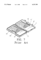
- FIG. 7 of the drawings illustrates a conventional toolbox having an upper casing 1' and a lower casing 2'.
- Each casing 1', 2' has a number of shaped grooves 11', 21' for receiving tools of different shapes and sizes.
- Each casing 1', 2' further has a handle 13, 23' for easy carriage.
- the upper casing 1' includes an engaging member 12' and the lower casing 2' has an engaging groove 22' for releasably engaging with the engaging member 12', thereby preventing falling of the tools out of the toolbox.
- a drawback of such a toolbox is that the user cannot know what types of tools are carried in the toolbox unless it is opened.
- the toolbox cannot be used to display the tools therein, as the casings 1' and 2' both lie on the ground or table.
- the tools tend to fall out of the toolbox when the toolbox is opened, as no retaining member is provided to retain the tools in place.
- the present invention is intended to provide an improved toolbox that mitigates and/or obviates the above problems.
- a toolbox in accordance with the present invention comprises a casing and a cover pivotally connected to and releasably engaged with the casing.
- the casing includes a plurality of shaped grooves for receiving tools and a handle.
- the casing includes a bottom having two first pivotal sections formed on two ends thereof, respectively. Each of two lower corner areas of the casing is cut to form a space.
- Each of two lateral walls of the casing includes an end face facing the space.
- the cover has two lateral sides with a view opening therebetween. Each lateral side has a second pivotal section pivotally engaged with an associated first pivotal section on the casing, thereby allowing relative pivotal movement between the cover and the casing.
- the cover is pivotable to a first position for engaging with the casing in which the tools are viewed via the view opening and a second position that supports the casing in an inclined status in which the end faces rest on an outer side of the cover.
- the pivotal sections of the casing are two holes in two lateral end faces of the bottom, respectively, and the pivotal sections of the cover are pintles pivotally received in the holes.
- the cover is substantially U-shape and has two arms. Each of two lateral sides of the casing has a recess in a lower portion thereof for receiving an associated arm of the cover when the casing is engaged with the cover. An end wall defining each recess has an engaging member formed thereon.
- the cover has two engaging members for releasably engaging with the engaging members on the casing. Each end face includes a first engaging portion, and each arm includes a second engaging portion configured to releasably engage with the first engaging portion of the casing when the casing is supported in the inclined status.
- the casing has a handle pivotally attached thereto and a recessed portion is defined in a rear side of the casing thereof for receiving the handle.
- the toolbox in accordance with the present invention is configured as a notebook and can be easily carried and supported in an inclined status for use or display.
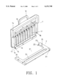
- FIG. 1 is an exploded perspective view of a toolbox in accordance with the present invention.
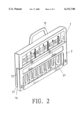
- FIG. 2 is a front perspective view of the toolbox in accordance with the present invention.
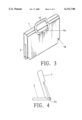
- FIG. 3 is a rear perspective view of the toolbox in accordance with the present invention.
- FIG. 4 is a side view of the toolbox in FIG. 2 in a status for display or use.
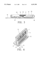
- FIG. 5 is a sectional view of the toolbox in accordance with the present invention.
- FIG. 6 is a perspective view of the toolbox in a status for display or use.
- FIG. 7 is a perspective view of a conventional toolbox.
- a toolbox in accordance with the present invention generally includes a casing 1 and a cover 2.
- the casing 1 includes a plurality of shaped grooves 11 defined in a side thereof for receiving tools of different shapes and sizes.
- the casing 1 further includes a handle 12 formed on top thereof.
- Each of two lateral walls of the casing 1 includes a recess 13 in a lower portion thereof, and an engaging member 14 is provided on an end face defining the recess 13.
- a bottom of the casing 1 includes two pivotal sections 15 (in the form of holes) in two lateral end faces thereof, respectively.
- Each of two lower comer areas of the casing 1 is cut to form a space 16.
- each of two lateral walls of the casing 1 includes an end face 17 facing the space 16.
- Each end face 17 further includes an engaging portion 18.
- the cover 2 is substantially U-shape and has two arms 26 with a view opening 21 therebetween.
- Each arm 26 has a pivotal section 22 (in the form of a pintle) formed thereon.
- the pintle 22 is pivotally engaged in an associated hole 15, thereby allowing relative pivotal movement between the cover 2 and the casing 1.
- the cover 2 further includes engaging members 23 for releasably engaging with the engaging members 14 on the casing 1.
- the cover 2 further includes a retaining ridge 24 on an inner side thereof that faces the shaped grooves 11.
- Each arm 26 further includes an engaging portion 25 configured to releasably engage with the engaging portion 18 of the casing 1.
- the pintles 22 of the cover 2 are pivotally received in the holes 15 of the casing 1.
- the cover 2 is pivoted to a position shown in FIG. 2 such that the tools may be retained in place by the retaining ridge 24 (FIG. 5), which is useful for carriage.
- all of the tools may be directly viewed via the view opening 21 in the cover 2.
- the casing 1 and the cover 2 are securely engaged together by means of engagement between the engaging members 14 and 23.
- the recesses 13 of the casing 1 receive two arms 26 of the cover 2, thereby providing an aesthetically pleasing effect.
- the cover 2 When the user intends to use the tools or display the tools, the cover 2 may be pivoted to a position shown in FIGS. 4 and 6 until the outer side of the cover 2 abuts the end faces 17 of the casing 1, thereby providing a reliable support for the casing 1 in an inclined status.
- the tools in the casing 1 may be displayed or accessed easily.
- the toolbox is reliably retained in the inclined status by means of engagement between the engaging portions 18 and 25.
- the casing 1 may include a recessed portion 19 in a rear side thereof for receiving the handle 12 that is pivotally attached to the casing 1.
- the overall appearance for the toolbox is aesthetically pleasing when in the status for use or display, best shown in FIGS. 4 and 6.
- the toolbox in accordance with the present invention is configured as a notebook and can be easily carried and supported in an inclined status for use or display.
Abstract
A notebook type toolbox includes a casing and a cover pivotally connected to and releasably engaged with the casing. The casing includes shaped grooves for receiving tools and a handle. A bottom of the casing includes two pivotal sections in two ends thereof, respectively. Each of two lower corner areas of the casing is cut to form a space. Each of two lateral walls of the casing includes an end face facing the space. The cover has two lateral sides with a view opening therebetween. Each lateral side has a pivotal section pivotally engaged with an associated pivotal section on the casing. The cover is pivotable to a first position for engaging with the casing in which the tools can be viewed via the view opening and a second position that supports the casing in an inclined status in which the end faces rest on an outer side of the cover.
Description
1. Field of the Invention
The present invention relates to a notebook type toolbox that may be used as a display device for tools and that allows easy access to the tools and provides reliable tool-retaining effect.
2. Description of the Related Art
FIG. 7 of the drawings illustrates a conventional toolbox having an upper casing 1' and a lower casing 2'. Each casing 1', 2' has a number of shaped grooves 11', 21' for receiving tools of different shapes and sizes. Each casing 1', 2' further has a handle 13, 23' for easy carriage. The upper casing 1' includes an engaging member 12' and the lower casing 2' has an engaging groove 22' for releasably engaging with the engaging member 12', thereby preventing falling of the tools out of the toolbox.
A drawback of such a toolbox is that the user cannot know what types of tools are carried in the toolbox unless it is opened. The toolbox cannot be used to display the tools therein, as the casings 1' and 2' both lie on the ground or table. In addition, the tools tend to fall out of the toolbox when the toolbox is opened, as no retaining member is provided to retain the tools in place.
The present invention is intended to provide an improved toolbox that mitigates and/or obviates the above problems.
A toolbox in accordance with the present invention comprises a casing and a cover pivotally connected to and releasably engaged with the casing. The casing includes a plurality of shaped grooves for receiving tools and a handle. The casing includes a bottom having two first pivotal sections formed on two ends thereof, respectively. Each of two lower corner areas of the casing is cut to form a space. Each of two lateral walls of the casing includes an end face facing the space. The cover has two lateral sides with a view opening therebetween. Each lateral side has a second pivotal section pivotally engaged with an associated first pivotal section on the casing, thereby allowing relative pivotal movement between the cover and the casing. The cover is pivotable to a first position for engaging with the casing in which the tools are viewed via the view opening and a second position that supports the casing in an inclined status in which the end faces rest on an outer side of the cover.
The pivotal sections of the casing are two holes in two lateral end faces of the bottom, respectively, and the pivotal sections of the cover are pintles pivotally received in the holes.
The cover is substantially U-shape and has two arms. Each of two lateral sides of the casing has a recess in a lower portion thereof for receiving an associated arm of the cover when the casing is engaged with the cover. An end wall defining each recess has an engaging member formed thereon. The cover has two engaging members for releasably engaging with the engaging members on the casing. Each end face includes a first engaging portion, and each arm includes a second engaging portion configured to releasably engage with the first engaging portion of the casing when the casing is supported in the inclined status.
The casing has a handle pivotally attached thereto and a recessed portion is defined in a rear side of the casing thereof for receiving the handle.
Thus, the toolbox in accordance with the present invention is configured as a notebook and can be easily carried and supported in an inclined status for use or display.
Other objects, advantages, and novel features of the invention will become more apparent from the following detailed description when taken in conjunction with the accompanying drawings.
FIG. 1 is an exploded perspective view of a toolbox in accordance with the present invention.
FIG. 2 is a front perspective view of the toolbox in accordance with the present invention.
FIG. 3 is a rear perspective view of the toolbox in accordance with the present invention.
FIG. 4 is a side view of the toolbox in FIG. 2 in a status for display or use.
FIG. 5 is a sectional view of the toolbox in accordance with the present invention.
FIG. 6 is a perspective view of the toolbox in a status for display or use.
FIG. 7 is a perspective view of a conventional toolbox.
Referring to FIGS. 1, 2, 5, and 6, a toolbox in accordance with the present invention generally includes a casing 1 and a cover 2. The casing 1 includes a plurality of shaped grooves 11 defined in a side thereof for receiving tools of different shapes and sizes. The casing 1 further includes a handle 12 formed on top thereof. Each of two lateral walls of the casing 1 includes a recess 13 in a lower portion thereof, and an engaging member 14 is provided on an end face defining the recess 13. A bottom of the casing 1 includes two pivotal sections 15 (in the form of holes) in two lateral end faces thereof, respectively. Each of two lower comer areas of the casing 1 is cut to form a space 16. Thus, each of two lateral walls of the casing 1 includes an end face 17 facing the space 16. Each end face 17 further includes an engaging portion 18.
The cover 2 is substantially U-shape and has two arms 26 with a view opening 21 therebetween. Each arm 26 has a pivotal section 22 (in the form of a pintle) formed thereon. The pintle 22 is pivotally engaged in an associated hole 15, thereby allowing relative pivotal movement between the cover 2 and the casing 1. The cover 2 further includes engaging members 23 for releasably engaging with the engaging members 14 on the casing 1. The cover 2 further includes a retaining ridge 24 on an inner side thereof that faces the shaped grooves 11. Each arm 26 further includes an engaging portion 25 configured to releasably engage with the engaging portion 18 of the casing 1.
In assembly, the pintles 22 of the cover 2 are pivotally received in the holes 15 of the casing 1. In use, after inserting tools into corresponding shaped grooves 11 in the casing 1, the cover 2 is pivoted to a position shown in FIG. 2 such that the tools may be retained in place by the retaining ridge 24 (FIG. 5), which is useful for carriage. In addition, all of the tools may be directly viewed via the view opening 21 in the cover 2. Thus, the user may check the tools without opening the toolbox. The casing 1 and the cover 2 are securely engaged together by means of engagement between the engaging members 14 and 23. The recesses 13 of the casing 1 receive two arms 26 of the cover 2, thereby providing an aesthetically pleasing effect.
When the user intends to use the tools or display the tools, the cover 2 may be pivoted to a position shown in FIGS. 4 and 6 until the outer side of the cover 2 abuts the end faces 17 of the casing 1, thereby providing a reliable support for the casing 1 in an inclined status. Thus, the tools in the casing 1 may be displayed or accessed easily. The toolbox is reliably retained in the inclined status by means of engagement between the engaging portions 18 and 25.
Referring to FIG. 3, the casing 1 may include a recessed portion 19 in a rear side thereof for receiving the handle 12 that is pivotally attached to the casing 1. Thus, the overall appearance for the toolbox is aesthetically pleasing when in the status for use or display, best shown in FIGS. 4 and 6. Thus, the toolbox in accordance with the present invention is configured as a notebook and can be easily carried and supported in an inclined status for use or display.
Although the invention has been explained in relation to its preferred embodiment, it is to be understood that many other possible modifications and variations can be made without departing from the spirit and scope of the invention as hereinafter claimed.
Claims (7)
1. A toolbox comprising a casing and a cover pivotally connected to and releasably engaged with the casing, the casing including a plurality of shaped grooves for receiving tools and a handle, the casing including a bottom having two first pivotal sections formed on two ends thereof, respectively, each of two lower corner areas of the casing being cut to form a space, each of two lateral walls of the casing including an end face facing the space, the cover having two lateral sides with a view opening therebetween, each lateral side having a second pivotal section pivotally engaged with an associated said first pivotal section on the casing, thereby allowing relative pivotal movement between the cover and the casing, the cover being pivotable to a first position for engaging with the casing in which the tools are viewed via the view opening and a second position that supports the casing in an inclined status in which the end faces rest on an outer side of the cover.
2. The toolbox as claimed in claim 1, wherein the pivotal sections of the casing are two holes in two lateral end faces of the bottom, respectively, and the pivotal sections of the cover are pintles pivotally received in the holes.
3. The toolbox as claimed in claim 1, wherein the cover is substantially U-shape and has two arms.
4. The toolbox as claimed in claim 3, wherein each of two lateral sides of the casing has a recess in a lower portion thereof for receiving an associated said arm of the cover when the casing is engaged with the cover.
5. The toolbox as claimed in claim 4, wherein an end wall defining each said recess has an engaging member formed thereon, and the cover has two engaging members for releasably engaging with the engaging members on the casing.
6. The toolbox as claimed in claim 3, wherein each said end face includes a first engaging portion, and wherein each said arm further includes a second engaging portion configured to releasably engage with the first engaging portion of the casing when the casing is supported in the inclined status.
7. The toolbox as claimed in claim 1, wherein the casing has a handle pivotally attached thereto, the casing further including a recessed portion in a rear side thereof for receiving the handle.
Priority Applications (3)
| Application Number | Priority Date | Filing Date | Title |
|---|---|---|---|
| DE29922871U DE29922871U1 (en) | 1999-12-28 | 1999-12-28 | Notebook type toolbox |
| US09/514,902 US6131740A (en) | 1999-12-28 | 2000-02-28 | Toolbox |
| GB0024856A GB2359542B (en) | 2000-02-28 | 2000-10-11 | Toolbox |
Applications Claiming Priority (2)
| Application Number | Priority Date | Filing Date | Title |
|---|---|---|---|
| DE29922871U DE29922871U1 (en) | 1999-12-28 | 1999-12-28 | Notebook type toolbox |
| US09/514,902 US6131740A (en) | 1999-12-28 | 2000-02-28 | Toolbox |
Publications (1)
| Publication Number | Publication Date |
|---|---|
| US6131740A true US6131740A (en) | 2000-10-17 |
Family
ID=26062943
Family Applications (1)
| Application Number | Title | Priority Date | Filing Date |
|---|---|---|---|
| US09/514,902 Expired - Fee Related US6131740A (en) | 1999-12-28 | 2000-02-28 | Toolbox |
Country Status (2)
| Country | Link |
|---|---|
| US (1) | US6131740A (en) |
| DE (1) | DE29922871U1 (en) |
Cited By (41)
| Publication number | Priority date | Publication date | Assignee | Title |
|---|---|---|---|---|
| US6450328B1 (en) * | 2000-05-15 | 2002-09-17 | Bisco, Inc. | Dental equipment and material storage and multi-positional display apparatus |
| US6523687B2 (en) * | 2001-02-23 | 2003-02-25 | Hand Tool Design Corporation | Toolbox with dual tool-receiving grooves and display in both sides thereof |
| US6581774B1 (en) * | 2000-11-13 | 2003-06-24 | Tramontine Usa, Inc. | Folding knife block apparatus |
| US6591985B2 (en) * | 2001-07-13 | 2003-07-15 | Ching-Hai Lai | Structure of toolbox |
| US20030213760A1 (en) * | 2002-05-16 | 2003-11-20 | Lee Yung Jen | Tool retaining device having stably retaining structure |
| US20030226779A1 (en) * | 2002-06-11 | 2003-12-11 | Tsai-Ching Chen | Self-opening tool box |
| US6745900B2 (en) * | 2001-09-21 | 2004-06-08 | Qualipac | Case with a foldable lid |
| US20040188322A1 (en) * | 2003-03-26 | 2004-09-30 | Kun-Chen Chen | Toolbox for displaying and storing tool heads |
| US20050098461A1 (en) * | 2003-11-07 | 2005-05-12 | Jui-Chien Kao | Tool suspension plate |
| US7100777B1 (en) * | 2005-07-07 | 2006-09-05 | Jui-Chien Kao | Hanger rack for hand tools |
| US20060207903A1 (en) * | 2002-06-11 | 2006-09-21 | Tsai-Ching Chen | Toolbox |
| US7111726B1 (en) * | 2004-06-16 | 2006-09-26 | Armanent Systems & Procedures, Inc. | Protective display and gift package |
| US20080060960A1 (en) * | 2006-09-13 | 2008-03-13 | Bobby Hu | Toolbox apparatus |
| US20080142653A1 (en) * | 2006-12-19 | 2008-06-19 | Hon Hai Precision Industry Co., Ltd. | Free-standing electronic device |
| US20090050499A1 (en) * | 2006-01-24 | 2009-02-26 | Calco Wayne A | Protective assembly for portable digital device |
| US20090101539A1 (en) * | 2007-10-22 | 2009-04-23 | Mingwei Qian | Microtube container and carrier for multiple containers |
| US8376153B1 (en) * | 2011-10-27 | 2013-02-19 | Hong-Jen Lee | Tool rack |
| US20140231307A1 (en) * | 2011-10-17 | 2014-08-21 | Shanghai Kunjek Handtools And Hardware Co., Ltd. | Method and apparatus for tool case |
| US20140272130A1 (en) * | 2013-03-13 | 2014-09-18 | Kenneth C. Alfter | Fluid Applicator |
| US20140262887A1 (en) * | 2013-03-15 | 2014-09-18 | Wagic, Inc. | Post lock tool holder for l-shaped wrenches |
| USD723276S1 (en) | 2013-03-15 | 2015-03-03 | Wagic, Inc. | Post lock tool holder for L-shaped wrenches |
| US9120208B2 (en) | 2009-10-05 | 2015-09-01 | WAGIC, Inc | Handled ratcheting tool with a flip out handle |
| US9193058B2 (en) | 2012-05-15 | 2015-11-24 | Wagic, Inc. | Adjustable tool handle for holding a tool during use |
| US9289894B2 (en) | 2007-05-10 | 2016-03-22 | Wagic, Inc. | Hand tool with multiple bit storage and a method for using the same |
| US9387579B2 (en) | 2012-05-15 | 2016-07-12 | Wagic, Inc. | Adjustable tool handle for holding a tool during use |
| US9505123B2 (en) | 2008-01-17 | 2016-11-29 | Wagic, Inc. | Tool holder |
| US9539720B2 (en) * | 2015-06-02 | 2017-01-10 | Yu-Hua Ou | Tool holder |
| US9545715B1 (en) * | 2015-07-20 | 2017-01-17 | Huang-Tung Hsu | Tool box |
| US9545707B2 (en) | 2008-01-17 | 2017-01-17 | Wagic, Inc. | Tool handle for holding multiple tools of different sizes during use |
| US9573270B2 (en) * | 2015-06-01 | 2017-02-21 | Yu-Hua Ou | Tool holder |
| US9604349B2 (en) | 2008-01-17 | 2017-03-28 | Wagic, Inc. | Universal ratcheting tool |
| US9627191B2 (en) | 2009-09-17 | 2017-04-18 | Wagic, Inc. | Extendable multi-tool including interchangable light bulb changer and accessories |
| US9676083B2 (en) | 2009-10-05 | 2017-06-13 | Wagic, Inc. | Dual purpose flip-out and T handle |
| US9701005B2 (en) | 2008-01-17 | 2017-07-11 | Wagic, Inc. | Biaxial foldout tool with multiple tools on a side and a rotational stop |
| US9809053B2 (en) | 2013-03-13 | 2017-11-07 | Kenneth C. Alfter | Fluid applicator |
| USD809598S1 (en) | 2013-07-12 | 2018-02-06 | Kenneth C. Alfter | Fluid applicator |
| US10723014B2 (en) | 2012-05-15 | 2020-07-28 | Wagic, Inc. | Tool holder for holding multiple tools of different sizes |
| US11224313B2 (en) * | 2018-12-12 | 2022-01-18 | Eivin Kilcher | Cutting board with internal storage for implements |
| US11246679B2 (en) * | 2019-03-26 | 2022-02-15 | Practicon, Inc. | Device for holding medical instruments and method of using same |
| USD943765S1 (en) | 2019-03-26 | 2022-02-15 | Practicon, Inc. | Bur holder |
| US20230189987A1 (en) * | 2021-01-27 | 2023-06-22 | Mark Wayne Rettig | Modular cleaning, display, and storage rack for firearms |
Citations (7)
| Publication number | Priority date | Publication date | Assignee | Title |
|---|---|---|---|---|
| US4930628A (en) * | 1988-11-21 | 1990-06-05 | Aladdin Industries Inc. | Storage and display case having pivotally mounted cover |
| US5692609A (en) * | 1996-12-03 | 1997-12-02 | Lin; Jyh-Sheng | Store box for dental equipment |
| US5775499A (en) * | 1995-08-21 | 1998-07-07 | Budert; Guenter H. | Tool holding apparatus |
| US5823353A (en) * | 1996-01-26 | 1998-10-20 | Perrin Manufacturing Company | Combination business card case and display case |
| US5918741A (en) * | 1997-01-14 | 1999-07-06 | Maxtech, Inc. | Tool case |
| US5927493A (en) * | 1997-05-09 | 1999-07-27 | Hardware Industrial Manufacturing S.R.L. | Blade-holding case for a hack sawing machine |
| US6050409A (en) * | 1996-05-22 | 2000-04-18 | Delbeck; Klaus | Storage device for screwdriver bits or the like and chuck therefor |
-
1999
- 1999-12-28 DE DE29922871U patent/DE29922871U1/en not_active Expired - Lifetime
-
2000
- 2000-02-28 US US09/514,902 patent/US6131740A/en not_active Expired - Fee Related
Patent Citations (7)
| Publication number | Priority date | Publication date | Assignee | Title |
|---|---|---|---|---|
| US4930628A (en) * | 1988-11-21 | 1990-06-05 | Aladdin Industries Inc. | Storage and display case having pivotally mounted cover |
| US5775499A (en) * | 1995-08-21 | 1998-07-07 | Budert; Guenter H. | Tool holding apparatus |
| US5823353A (en) * | 1996-01-26 | 1998-10-20 | Perrin Manufacturing Company | Combination business card case and display case |
| US6050409A (en) * | 1996-05-22 | 2000-04-18 | Delbeck; Klaus | Storage device for screwdriver bits or the like and chuck therefor |
| US5692609A (en) * | 1996-12-03 | 1997-12-02 | Lin; Jyh-Sheng | Store box for dental equipment |
| US5918741A (en) * | 1997-01-14 | 1999-07-06 | Maxtech, Inc. | Tool case |
| US5927493A (en) * | 1997-05-09 | 1999-07-27 | Hardware Industrial Manufacturing S.R.L. | Blade-holding case for a hack sawing machine |
Cited By (55)
| Publication number | Priority date | Publication date | Assignee | Title |
|---|---|---|---|---|
| US6450328B1 (en) * | 2000-05-15 | 2002-09-17 | Bisco, Inc. | Dental equipment and material storage and multi-positional display apparatus |
| US6581774B1 (en) * | 2000-11-13 | 2003-06-24 | Tramontine Usa, Inc. | Folding knife block apparatus |
| US6523687B2 (en) * | 2001-02-23 | 2003-02-25 | Hand Tool Design Corporation | Toolbox with dual tool-receiving grooves and display in both sides thereof |
| US6591985B2 (en) * | 2001-07-13 | 2003-07-15 | Ching-Hai Lai | Structure of toolbox |
| US6745900B2 (en) * | 2001-09-21 | 2004-06-08 | Qualipac | Case with a foldable lid |
| US20030213760A1 (en) * | 2002-05-16 | 2003-11-20 | Lee Yung Jen | Tool retaining device having stably retaining structure |
| US20060207903A1 (en) * | 2002-06-11 | 2006-09-21 | Tsai-Ching Chen | Toolbox |
| US20030226779A1 (en) * | 2002-06-11 | 2003-12-11 | Tsai-Ching Chen | Self-opening tool box |
| US20040188322A1 (en) * | 2003-03-26 | 2004-09-30 | Kun-Chen Chen | Toolbox for displaying and storing tool heads |
| US20050098461A1 (en) * | 2003-11-07 | 2005-05-12 | Jui-Chien Kao | Tool suspension plate |
| US7080733B2 (en) * | 2003-11-07 | 2006-07-25 | Jui-Chien Kao | Tool suspension plate |
| US7111726B1 (en) * | 2004-06-16 | 2006-09-26 | Armanent Systems & Procedures, Inc. | Protective display and gift package |
| US7100777B1 (en) * | 2005-07-07 | 2006-09-05 | Jui-Chien Kao | Hanger rack for hand tools |
| US20090050499A1 (en) * | 2006-01-24 | 2009-02-26 | Calco Wayne A | Protective assembly for portable digital device |
| US20080060960A1 (en) * | 2006-09-13 | 2008-03-13 | Bobby Hu | Toolbox apparatus |
| US7559427B2 (en) * | 2006-09-13 | 2009-07-14 | Bobby Hu | Toolbox apparatus |
| US20080142653A1 (en) * | 2006-12-19 | 2008-06-19 | Hon Hai Precision Industry Co., Ltd. | Free-standing electronic device |
| US9289894B2 (en) | 2007-05-10 | 2016-03-22 | Wagic, Inc. | Hand tool with multiple bit storage and a method for using the same |
| US20090101539A1 (en) * | 2007-10-22 | 2009-04-23 | Mingwei Qian | Microtube container and carrier for multiple containers |
| US8215480B2 (en) | 2007-10-22 | 2012-07-10 | Occam Biolabs, Inc. | Microtube container and carrier for multiple containers |
| US10442069B2 (en) | 2008-01-17 | 2019-10-15 | Wagic, Inc. | Biaxial foldout tool with multiple tools on a side and a rotational stop |
| US10434631B2 (en) | 2008-01-17 | 2019-10-08 | Wagic, Inc. | Universal ratcheting tool |
| US10322503B2 (en) | 2008-01-17 | 2019-06-18 | Wagic, Inc. | Tool handle for holding multiple tools of different sizes during use |
| US9701005B2 (en) | 2008-01-17 | 2017-07-11 | Wagic, Inc. | Biaxial foldout tool with multiple tools on a side and a rotational stop |
| US9505123B2 (en) | 2008-01-17 | 2016-11-29 | Wagic, Inc. | Tool holder |
| US9604349B2 (en) | 2008-01-17 | 2017-03-28 | Wagic, Inc. | Universal ratcheting tool |
| US9545707B2 (en) | 2008-01-17 | 2017-01-17 | Wagic, Inc. | Tool handle for holding multiple tools of different sizes during use |
| US10371360B2 (en) | 2009-09-17 | 2019-08-06 | Wagic, Inc. | Extendable multi-tool including interchangable light bulb changer and accessories |
| US9627191B2 (en) | 2009-09-17 | 2017-04-18 | Wagic, Inc. | Extendable multi-tool including interchangable light bulb changer and accessories |
| US9676083B2 (en) | 2009-10-05 | 2017-06-13 | Wagic, Inc. | Dual purpose flip-out and T handle |
| US9120208B2 (en) | 2009-10-05 | 2015-09-01 | WAGIC, Inc | Handled ratcheting tool with a flip out handle |
| US10343273B2 (en) | 2009-10-05 | 2019-07-09 | Wagic, Inc. | Dual purpose flip-out and T handle |
| US20140231307A1 (en) * | 2011-10-17 | 2014-08-21 | Shanghai Kunjek Handtools And Hardware Co., Ltd. | Method and apparatus for tool case |
| US8376153B1 (en) * | 2011-10-27 | 2013-02-19 | Hong-Jen Lee | Tool rack |
| US9193058B2 (en) | 2012-05-15 | 2015-11-24 | Wagic, Inc. | Adjustable tool handle for holding a tool during use |
| US10207400B2 (en) | 2012-05-15 | 2019-02-19 | Wagic, Inc. | Adjustable tool handle for holding a tool during use |
| US9387579B2 (en) | 2012-05-15 | 2016-07-12 | Wagic, Inc. | Adjustable tool handle for holding a tool during use |
| US10723014B2 (en) | 2012-05-15 | 2020-07-28 | Wagic, Inc. | Tool holder for holding multiple tools of different sizes |
| US9314094B2 (en) * | 2013-03-13 | 2016-04-19 | Kenneth C. Alfter | Fluid applicator |
| US20140272130A1 (en) * | 2013-03-13 | 2014-09-18 | Kenneth C. Alfter | Fluid Applicator |
| US9809053B2 (en) | 2013-03-13 | 2017-11-07 | Kenneth C. Alfter | Fluid applicator |
| US20140262887A1 (en) * | 2013-03-15 | 2014-09-18 | Wagic, Inc. | Post lock tool holder for l-shaped wrenches |
| US10239197B2 (en) * | 2013-03-15 | 2019-03-26 | Wagic, Inc. | Post lock tool holder for L-shaped wrenches |
| USD723276S1 (en) | 2013-03-15 | 2015-03-03 | Wagic, Inc. | Post lock tool holder for L-shaped wrenches |
| US20160039087A1 (en) * | 2013-03-15 | 2016-02-11 | Wagic, Inc. | Post lock tool holder for l-shaped wrenches |
| US9193062B2 (en) * | 2013-03-15 | 2015-11-24 | Wagic, Inc. | Post lock tool holder for L-shaped wrenches |
| USD809598S1 (en) | 2013-07-12 | 2018-02-06 | Kenneth C. Alfter | Fluid applicator |
| US9573270B2 (en) * | 2015-06-01 | 2017-02-21 | Yu-Hua Ou | Tool holder |
| US9539720B2 (en) * | 2015-06-02 | 2017-01-10 | Yu-Hua Ou | Tool holder |
| US9545715B1 (en) * | 2015-07-20 | 2017-01-17 | Huang-Tung Hsu | Tool box |
| US11224313B2 (en) * | 2018-12-12 | 2022-01-18 | Eivin Kilcher | Cutting board with internal storage for implements |
| US11246679B2 (en) * | 2019-03-26 | 2022-02-15 | Practicon, Inc. | Device for holding medical instruments and method of using same |
| USD943765S1 (en) | 2019-03-26 | 2022-02-15 | Practicon, Inc. | Bur holder |
| US20230189987A1 (en) * | 2021-01-27 | 2023-06-22 | Mark Wayne Rettig | Modular cleaning, display, and storage rack for firearms |
| US11896123B2 (en) * | 2021-01-27 | 2024-02-13 | Mark Wayne Rettig | Modular cleaning, display, and storage rack for firearms |
Also Published As
| Publication number | Publication date |
|---|---|
| DE29922871U1 (en) | 2000-03-23 |
Similar Documents
| Publication | Publication Date | Title |
|---|---|---|
| US6131740A (en) | Toolbox | |
| US5244084A (en) | Laser disk carrying case | |
| US5893457A (en) | Tool box | |
| US5067617A (en) | Earring storage and display rack | |
| US5915554A (en) | Tool box assembly with a swivel tool rack | |
| USD421879S (en) | Knife block with slot recess | |
| US20040020880A1 (en) | Tool display device | |
| USD412319S (en) | Docking device for portable computer | |
| US5788303A (en) | Portable wrench rack | |
| USD443417S1 (en) | Notebook computer carrying case with accessory pockets | |
| USD456398S1 (en) | Portable computer | |
| KR19990072995A (en) | Cabinet having a tambour door and an attatchment mechanism | |
| USD410178S (en) | Hinge pin extractor | |
| US20020060512A1 (en) | Enclosure having pivotable bezel | |
| USD409020S (en) | Computer keyboard stand with arm support | |
| US5603480A (en) | Keyboard stand mounting structure | |
| USD412161S (en) | Base for a computer display | |
| USD427191S (en) | Computer housing | |
| USD443983S1 (en) | Notebook computer case | |
| USD466897S1 (en) | Combined display monitor and data copying machine | |
| US20040188293A1 (en) | Bucket type tool box | |
| USD451306S1 (en) | Portable computer stand | |
| GB2359542A (en) | Toolbox | |
| US5213229A (en) | Motion limiting mechanism for storage containers | |
| USD440955S1 (en) | Portable telephone |
Legal Events
| Date | Code | Title | Description |
|---|---|---|---|
| REMI | Maintenance fee reminder mailed | ||
| LAPS | Lapse for failure to pay maintenance fees | ||
| STCH | Information on status: patent discontinuation |
Free format text: PATENT EXPIRED DUE TO NONPAYMENT OF MAINTENANCE FEES UNDER 37 CFR 1.362 |
|
| FP | Expired due to failure to pay maintenance fee |
Effective date: 20041017 |