US6137837A - Motion estimation for digital video with reduced number of search window pixels - Google Patents
Motion estimation for digital video with reduced number of search window pixels Download PDFInfo
- Publication number
- US6137837A US6137837A US09/012,815 US1281598A US6137837A US 6137837 A US6137837 A US 6137837A US 1281598 A US1281598 A US 1281598A US 6137837 A US6137837 A US 6137837A
- Authority
- US
- United States
- Prior art keywords
- search window
- pattern
- pixel
- pixels
- image
- Prior art date
- Legal status (The legal status is an assumption and is not a legal conclusion. Google has not performed a legal analysis and makes no representation as to the accuracy of the status listed.)
- Expired - Lifetime
Links
- 238000000034 method Methods 0.000 claims abstract description 21
- 239000013598 vector Substances 0.000 claims description 23
- 238000012545 processing Methods 0.000 abstract description 9
- 230000009467 reduction Effects 0.000 description 25
- OSWPMRLSEDHDFF-UHFFFAOYSA-N methyl salicylate Chemical compound COC(=O)C1=CC=CC=C1O OSWPMRLSEDHDFF-UHFFFAOYSA-N 0.000 description 14
- 230000006870 function Effects 0.000 description 10
- 230000006835 compression Effects 0.000 description 9
- 238000007906 compression Methods 0.000 description 9
- 229910003460 diamond Inorganic materials 0.000 description 8
- 239000010432 diamond Substances 0.000 description 8
- 230000005055 memory storage Effects 0.000 description 8
- 238000012360 testing method Methods 0.000 description 8
- 241000023320 Luma <angiosperm> Species 0.000 description 7
- 230000006872 improvement Effects 0.000 description 7
- 230000005540 biological transmission Effects 0.000 description 5
- 238000004364 calculation method Methods 0.000 description 4
- 238000005070 sampling Methods 0.000 description 4
- 230000008901 benefit Effects 0.000 description 3
- 230000015556 catabolic process Effects 0.000 description 3
- 238000006731 degradation reaction Methods 0.000 description 3
- 238000004088 simulation Methods 0.000 description 3
- 230000003044 adaptive effect Effects 0.000 description 2
- 238000004422 calculation algorithm Methods 0.000 description 2
- 238000006073 displacement reaction Methods 0.000 description 2
- 230000008569 process Effects 0.000 description 2
- 238000012935 Averaging Methods 0.000 description 1
- 238000009825 accumulation Methods 0.000 description 1
- 230000006978 adaptation Effects 0.000 description 1
- 238000003491 array Methods 0.000 description 1
- 230000008859 change Effects 0.000 description 1
- 238000011161 development Methods 0.000 description 1
- 238000001914 filtration Methods 0.000 description 1
- 238000012423 maintenance Methods 0.000 description 1
- 238000012986 modification Methods 0.000 description 1
- 230000004048 modification Effects 0.000 description 1
- 230000000750 progressive effect Effects 0.000 description 1
- 238000013139 quantization Methods 0.000 description 1
Images


Classifications
-
- H—ELECTRICITY
- H04—ELECTRIC COMMUNICATION TECHNIQUE
- H04N—PICTORIAL COMMUNICATION, e.g. TELEVISION
- H04N19/00—Methods or arrangements for coding, decoding, compressing or decompressing digital video signals
- H04N19/50—Methods or arrangements for coding, decoding, compressing or decompressing digital video signals using predictive coding
- H04N19/503—Methods or arrangements for coding, decoding, compressing or decompressing digital video signals using predictive coding involving temporal prediction
- H04N19/51—Motion estimation or motion compensation
Definitions
- the present invention relates to a method and apparatus for efficient motion estimation of a digital video image wherein memory capacity and processing requirements are reduced.
- the invention is suitable for use in coding compressed digital video images such as those conforming to the MPEG-2 standard.
- Digital transmission of television signals can deliver video and audio services of much higher quality than previous analog techniques. Digital transmission schemes are particularly advantageous for signals that are broadcast by satellite to cable television affiliates and/or directly to home satellite television receivers. Such signals can also be transmitted via a cable television network. Additionally, with the development of digital video storage media such as Digital Video Disks (DVDs), consumers now have the capability to store and retrieve compressed digital video in their homes.
- DVDs Digital Video Disks
- Video compression techniques enable the efficient transmission and storage of digital video signals. Such techniques use compression algorithms that take advantage of the correlation among adjacent pixels in order to derive a more efficient representation of the important information in a video signal.
- the most powerful compression systems not only take advantage of spatial correlation, but can also utilize similarities among adjacent frames to further compact the data.
- differential encoding is used to transmit only the difference between an actual frame and a prediction of the actual frame. The prediction is based on information derived from a previous frame of the same video sequence.
- motion vectors are derived by comparing a portion (i.e., macroblock) of pixel data from a current frame to similar portions of the previous frame.
- the previous frame in transmission order can be either previous or subsequent in display order.
- a motion estimator determines how the corresponding motion vector in the previous frame should be adjusted in order to be used in the current field. Such systems are very effective in reducing the amount of data to be transmitted.
- a 16 ⁇ 16 pixel macroblock in a frame which is currently being coded may be compared to a 128 ⁇ 96 or 128 ⁇ 64 search window of a previous or subsequent frame to determine which 16 ⁇ 16 pixel comparison region (e.g., block) in the search window most closely matches the macroblock.
- the criteria for the best match may be defined for each comparison region by summing the absolute values of the pixel differences, or the square of the pixel differences, for each region, and selecting the region with the lowest error.
- subsampling and averaging schemes may be used to effectively reduce the size of the current macroblock or search window, but this can reduce image quality due to the lost pixel information. Moreover, further computations are required.
- the system should be compatible with both frame (e.g., progressive) and field (e.g., interlaced) mode digital video.
- the system should reduce computational and memory storage requirements while also maintaining a satisfactory video image.
- the system should further be compatible with existing video compression techniques such as those conforming to the MPEG-2 standard.
- the system should reduce the amount of pixel data from a current macroblock which is used for motion estimation, as well as reducing the amount of pixel data from a search window which is used for motion estimation.
- the required computations and memory storage capacity should be reduced by up to 50% or more.
- the present invention provides a system having the above and other advantages.
- the present invention relates to a method and apparatus for efficient motion estimation of a digital video image wherein memory capacity and processing requirements are reduced. Only a portion of the pixel data of a search window is required to perform motion estimation.
- the method comprises the steps of retrieving a reduced number of pixels from the region to form the search window according to a search window pattern, where the reduced number is less than the second defined number, and comparing a reduced number of pixels of the current video image which is less than the first defined number to different comparison regions of the search window according to a current image pattern to obtain corresponding error values.
- the current image pattern which corresponds to the search window pattern, is alternated between first and second patterns for successive comparison regions while the search window pattern is fixed.
- the second pattern may be an inverse image of the first pattern.
- the search window pattern may comprise a fixed checkerboard pattern while the current image pattern is alternated between first and second checkerboard patterns for successive comparison regions, where the second checkerboard pattern is defined as an inverse image of the first checkerboard pattern.
- the current video image may comprise a field mode image with first and second fields, in which case the search window is formed for the first field using alternate rows of the search window pattern.
- the search window pattern may comprise a fixed checkerboard pattern while the current image pattern comprises a checkerboard pattern which is alternated between first and second patterns for successive comparison regions, where the second checkerboard pattern is defined according to the first checkerboard pattern, and the search window for the first field comprises columns of pixels.
- FIG. 1 illustrates a digital video compression circuit in accordance with the present invention.
- FIG. 2 illustrates motion estimation in accordance with the present invention.
- FIG. 3 illustrates a checkerboard pixel pattern for motion estimation with a 50% reduction in the pixel data of the current macroblock in accordance with the present invention.
- FIG. 4 illustrates an alternative checkerboard pixel pattern for motion estimation with a 50% reduction in the pixel data of the current macroblock in accordance with the present invention.
- FIG. 5 illustrates a diagonal pixel pattern for motion estimation with a 75% reduction in the pixel data of the current macroblock in accordance with the present invention.
- FIG. 6 illustrates another diagonal pixel pattern for motion estimation with an 87.5% reduction in the pixel data of the current macroblock in accordance with the present invention.
- FIG. 7 illustrates yet another diagonal pixel pattern for motion estimation with an 93.75% reduction in the pixel data of the current macroblock in accordance with the present invention.
- FIG. 8 illustrates a pixel pattern for motion estimation with a 25% reduction in the pixel data of the current macroblock in accordance with the present invention.
- FIG. 9 illustrates a horizontally and vertically symmetrical sparse pixel pattern for motion estimation with a 75% reduction in the pixel data of the current macroblock in accordance with the present invention.
- FIG. 10 illustrates an X shaped pixel pattern for motion estimation with an 88.3% reduction in the pixel data of the current macroblock in accordance with the present invention.
- FIG. 11 illustrates a diamond shaped pattern for motion estimation with a 78.1% reduction in the pixel data of the current macroblock in accordance with the present invention.
- FIG. 12 illustrates a pixel pattern for motion estimation with a 50% reduction in the pixel data of the search window in accordance with the present invention.
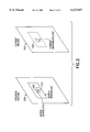
- FIG. 13 illustrates motion estimation with the pixel pattern of FIG. 12.
- FIG. 14 illustrates motion estimation for field mode video in accordance with the present invention.
- FIG. 15 illustrates motion estimation with the pixel pattern of FIG. 14.
- the present invention relates to a method and apparatus for efficient motion estimation of a digital video image wherein memory capacity and processing requirements are reduced.
- FIG. 1 illustrates a digital video compression circuit in accordance with the present invention.
- the compression circuit 100 includes a digitizer 110 which samples an input video signal, including a luminance signal (Y), and two color difference signals (Cr, Cb).
- An input sync signal is used for obtaining a sampling clock.
- the sampling clock rate for the Society of Motion Picture and Television Engineers (SMPTE) 125M specification 29.97 Hz video is 27 MHz.
- the digitized signal of a current image such as a current frame is subtracted from a predicted image from a previous or subsequent frame for inter-frame coding.
- a zero value is received from a multiplexer 185.
- a differential signal is obtained which allows the current frame to be reconstructed at a decoder.
- a Discrete Cosine Transform (DCT) function 125 takes 8 ⁇ 8 arrays of differential pixel magnitudes and converts them to frequency components.
- a quantizer 130 quantizes the frequency components, typically allocating more bits for low frequency components which are more visible to the human eye, while allocating fewer or even zero bits for the high frequency components. The quantizer receives information from a rate controller 135 to determine the bit allocation.
- DCT Discrete Cosine Transform
- the quantized frequency components are variable length coded at a coding function 140, then stored in a buffer 145, if required, to provide an elementary stream which is transmitted to a decoder.
- the current image is reconstructed by reversing the steps of the DCT 125 and quantizer 130 in an inverse quantizer 150 and inverse DCT function 160, respectively.
- the differential current image in the pixel domain which is output from the inverse DCT 160 is summed with the predicted image at an adder 165 to obtain the reconstructed current image.
- the reconstructed image essentially corresponds to the image which will be reconstructed at the decoders. It should closely correspond to the input image at the digitizer, although some information may be lost due to the quantization.
- the reconstructed current image is then provided to a motion compensator 170 to produce the predicted image using motion vectors from a motion estimator 175.
- the motion estimator 175 searches a search window of a previously coded image to find a region (e.g., best match region or block) which most closely matches the current image.
- a motion vector which is represented by x and y components in pixel lengths, defines the best-match region of the search area for each macroblock in the current image.
- the circuitry of the motion estimator 175 is typically the most computationally intensive element in the circuit 100.
- the predicted image is also provided to an intra/inter decision function 180 which determines whether inter-frame or intra-frame coding of the current macroblock should be used.
- a corresponding control signal is sent to the multiplexer 185.
- FIG. 2 illustrates motion estimation in accordance with the present invention.
- a current picture 200 also referred to as a reference picture, typically includes a plurality of macroblocks, including a macroblock 205, also referred to as a reference macroblock or block.
- a previous picture 220 is a picture which was coded before the current picture, e.g., in transmission order. However, the previous picture 220 may be either before or after the current picture in display order.
- the previous picture 220 includes a search window 225.
- a 128 ⁇ 64 search window for example, actually encompasses (128+16) ⁇ (64+16) pixels due to the height and width of the current macroblock.
- Other search window sizes may be used, of course.
- the search window is typically rectangular since horizontal motion is more probable than vertical motion in most video sequences.
- Region 225' in the current picture 200 is co-sited with the search window 225 and is shown for illustrative purposes.
- Each 16 ⁇ 16 comparison region is defined by shifting one pixel horizontally or vertically from a previous region. Thus, there is a large overlap between neighboring comparison regions.
- the comparison region 205 which is located in the same relative position within the overall picture as the current macroblock 205' is said to be co-sited with the current macroblock.
- the position of a current macroblock, or comparison region in a search window is defined by the upper left-hand coordinate of the macroblock or comparison search region such that the comparison region in the search window 225 which most closely matches the reference macroblock 205' can be defined by a horizontal and vertical displacement, e.g., a motion vector.
- the displacement of the best-match comparison region relative to the current macroblock is (0,0) if the best-match comparison region is co-sited with the current macroblock.
- positive values of the motion vector components indicate that the best-match comparison region block is to the right of, and below, the current macroblock, or equivalently, the co-sited comparison region.
- a motion vector of (5,6) indicates that the upper left-hand pixel of the best-match comparison region is five pixels to the right of, and six pixels below, the upper left-hand pixel of the co-sited comparison region or, equivalently, the upper left-hand pixel of the current macroblock.
- a best-match region 210 and motion vector 215 are shown for the current macroblock 205'.
- the best match comparison region can be determined according to a linear or second order error function.
- a sum of absolute errors term D.sup.(1) is defined conventionally as the sum of the absolute pixel errors d i ,j at the ith row and jth column between every corresponding pixel in the current luminance macroblock and the comparison region, e.g., ##EQU1##
- a sum of squared error terms D.sup.(2) is define as ##EQU2##
- determining the error using every pixel in the current macroblock requires that the data for each pixel is retrieved and stored in memory, such as random access memory (RAM), so that it is available for immediate use by a CPU or other computational circuit. Additionally, with real-time processing, the error calculations must be performed within a constrained time limit.
- RAM random access memory
- FIG. 3 illustrates a checkerboard pixel pattern for motion estimation with a 50% reduction in the pixel data of the current macroblock in accordance with the present invention.
- the current macroblock 300 which may correspond to the macroblock 205' of FIG. 2, is illustrated as a 16 ⁇ 16 luminance macroblock in the present example. However, it should be appreciate that different sized macroblocks or blocks may be used. Alternatively, the image area need not be square or rectangular, but may have an arbitrary shape. In any case, the current image is defined by some bounded region.
- the scheme can be adapted for use with chrominance pixel components according to the particular sampling format, e.g., 4:2:0.
- a portion of the current macroblock pixel data 300 is retrieved by a motion estimation circuit and stored in memory according to a current image pattern which is designated by the shaded areas.
- the current macroblock includes rows 0-15.
- rows 0, 2, 4, 6, 8, 10, 12 and 14 represent a top or even field, while rows 1, 3, 5, 7, 9, 11, 13 and 15 represent a bottom or odd field.
- the current macroblock is comprised of the pixel data from each of the shaded areas of rows 0-15.
- the subset is 50%, or 128 out of 256 pixels.
- the grid or pattern shown includes shaded regions, such as 305 and 310, which indicate that the correspondingly positioned pixel is retrieved and used for motion estimation.
- the unshaded regions, such as 315 and 320, indicate that the correspondingly positioned pixel is not retrieved and used for motion estimation.
- the pattern shown forms a checkerboard pattern, also known as a quincunx pattern. Every other pixel in the horizontal and vertical directions is selected for use in motion estimation, while the remaining pixels are not selected. In the example shown, the required memory capacity for storing the current macroblock can be reduced by 50%. Generally, with this embodiment, it is necessary to continue to retrieve all pixels in the search window for comparison with the designated current macroblock pixels. This is true since all of the search window pixels typically will be required at one point or another to perform the error calculations as the current macroblock is overlaid with the different comparison regions in the search window.
- a reduced number of search window pixels may be used with the same motion estimation performance relative to the reduced current macroblock pattern of FIG. 3.
- some portions of the search window may not be needed for motion compensation.
- the pixel data of the upper right-most and lower left-most triangular portions of the search window are not used for motion compensation and therefore need not be retrieved.
- the selected current macroblock pattern should not noticeably reduce the quality of the coded image.
- the seemingly disparate goals of reduced memory storage and computational requirements, together with the maintenance of satisfactory image quality in the coded image, can be achieved.
- FIG. 4 illustrates an alternative checkerboard pixel pattern for motion estimation with a 50% reduction in the pixel data of the current macroblock in accordance with the present invention.
- groups of four neighboring (e.g., contiguous) pixels are used.
- the designated pixels of the current macroblock 400 are shown by the shaded regions, such as a region 405, which indicates that the corresponding four pixels are retrieved and used for motion estimation.
- the unshaded regions, such as region 410 includes four pixels which are not used in motion compensation.
- the pattern repeats in the horizontal and vertical directions.
- FIG. 5 illustrates a diagonal pixel pattern for motion estimation with a 75% reduction in the pixel data of the current macroblock in accordance with the present invention.
- the designated pixels of the current macroblock 500 are shown by shaded diagonal regions, such as a region 505 which includes sixteen pixels.
- the unshaded regions designate pixel locations of the current macroblock which are not used in motion compensation and therefore need not be retrieved.
- diagonal patterns effectively detect motion which is horizontal, vertical, or diagonal in the direction of the diagonal, but may not effectively detect motion which is perpendicular to the diagonal.
- FIG. 6 illustrates another diagonal pixel pattern for motion estimation with an 87.5% reduction in the pixel data of the current macroblock in accordance with the present invention.
- the designated pixels of the current macroblock 600 are shown by shaded diagonal regions, such as a region 605 which includes sixteen pixels.
- the unshaded regions designate pixel locations of the current macroblock which are not used in motion compensation.
- FIG. 7 illustrates yet another diagonal pixel pattern for motion estimation with an 93.75% reduction in the pixel data of the current macroblock in accordance with the present invention.
- the designated pixels of the current macroblock 700 are shown by a shaded diagonal region 705 which includes sixteen pixels.
- the unshaded regions designate pixel locations of the current macroblock which are not used in motion compensation.
- the pixel data of the upper right-most and lower left-most triangular portions of the search window are not used for motion compensation and therefore need not be retrieved. This can result in a memory capacity savings of 240 pixels (e.g., 256-16).
- FIG. 8 illustrates a pixel pattern for motion estimation with a 25% reduction in the pixel data of the current macroblock in accordance with the present invention.
- all of the pixels in alternating horizontal rows are used for motion compensation, while half of the pixels in the remaining rows are used.
- a total of 192 out of 256 available pixels in the current macroblock are used, resulting in an efficiency improvement of 25%.
- all pixels in a first row 805 are used for motion compensation, while in a second row 810, only every other pixel is used.
- horizontal motion is more probable than vertical motion in video motion sequences.
- the football may move horizontally across the video frame.
- a moving vertical edge of the object e.g., football
- the vertical edge of an object which is moving horizontally in a video sequence it is desirable to use successive horizontally neighboring pixels for motion estimation.
- the pattern disclosed achieves the desired objective while still reducing computational and memory storage requirements.
- FIG. 9 illustrates a horizontally and vertically symmetrical sparse pixel pattern for motion estimation with a 75% reduction in the pixel data of the current macroblock in accordance with the present invention.
- the current macroblock 900 uses every other pixel in the horizontal and vertical directions for motion estimation, such as pixel 905. Rows and columns of pixels, such as row 915 and column 910 are not used. The designated pixels are symmetrically spaced horizontally and vertically in the current macroblock 900.
- FIG. 10 illustrates an X shaped pixel pattern for motion estimation with an 88.3% reduction in the pixel data of the current macroblock 1000 in accordance with the present invention. Thirty of the 256 pixels are used for motion compensation according to the "X" pattern shown. The pattern is formed by diagonal lines 1010 and 1020. Generally, an "X" pattern effectively detects motion in all directions.
- FIG. 11 illustrates a diamond shaped pattern for motion estimation with a 78.1% reduction in the pixel data of the current macroblock 1100 in accordance with the present invention.
- the diamond pattern shown fifty-six of the 256 pixels are used for motion compensation.
- Other diamond patterns may be formed by varying the size of each diamond.
- a current macroblock may have just one diamond.
- FIG. 12 illustrates a pixel pattern for motion estimation with a 50% reduction in the pixel data of the search window in accordance with the present invention.
- the required pixel data in the search window rather than the current macroblock is reduced.
- a search window 1210 is shown as having one hundred pixel positions, numbered from 0-99, but only the shaded positions are required for motion estimation. Thus, only fifty pixels are required, resulting in a 50% savings in memory and computations.
- pixels are numbered 0, 2, 4, 6, 8, 11, 13, 15, 17, 19, 20, 22, 24, 26, 28, 31, 33, 35, 37, 39, 40, 42, 44, 46, 48, 51, 53, 55, 57, 59, 60, 62, 64, 66, 68, 71, 73, 75, 77, 79, 80, 82, 84, 86, 88, 91, 93, 95, 97 and 99.
- a 50% savings in memory for the search window is larger in absolute terms (e.g., megabytes) than a 50% saving in memory for a current macroblock since the search window is significantly larger than a macroblock, for example, by a factor of eight or sixteen.
- a current block 1200 is illustrated for simplicity as having 4 ⁇ 4 pixels, with pixel positions labeled from A-P.
- 16 ⁇ 16 macroblocks are used for the current image, and a larger search window is used, e.g., 128 ⁇ 64.
- FIG. 13 illustrates motion estimation with the pixel pattern of FIG. 12.
- the pixel data of a current block is compared to successive comparison positions of the search window to determine which comparison position most closely matches the current block.
- a first comparison position 1310 the current block is overlaid with a 4 ⁇ 4 region at the upper left-hand corner of the search window to calculate the block error.
- pixel "A” in the current block 1200 is compared to pixel "O” in the comparison region
- pixel "C” is compared to pixel "2”
- pixel "F” is compared to pixel "11”
- pixel "H” is compared to pixel "13”
- pixel "I” is compared to pixel "20”
- pixel "K” is compared to pixel "22”
- pixel "N” is compared to pixel "31”
- pixel "P” is compared to pixel "33”.
- a sum of errors term can therefore be calculated, as discussed previously, for the first comparison region 1310.
- the current block 1200 is shifted one pixel to the right in the search window 1210 for comparison with a region 1320.
- six of the search window pixels which were used in the first comparison region 1310 are used again, with the addition of two other pixels, "4" and "24".
- the current block pixels which are used are the ones which were not used in the previous comparison.
- pixel "B” is compared to pixel "2"
- pixel "D” is compared to pixel "4"
- pixel "E” is compared to pixel "11”
- pixel "G” is compared to pixel “13”
- pixel "J” is compared to pixel "22”
- pixel "L” is compared to pixel "24”
- pixel "M” is compared to pixel "31”
- pixel "O” is compared to pixel "33”.
- a third step the current block is again shifted one pixel to the right for comparison with a region 1330.
- the same current macroblock pixels are used for the third step as were used in the first step with the region 1310.
- six of the same search window pixels are used with the addition of two new pixels, namely "15" and "35".
- pixel "A” is compared to pixel “2”
- pixel “C” is compared to pixel "4"
- pixel "F” is compared to pixel “13”
- pixel "H” is compared to pixel “15”
- pixel "I” is compared to pixel "22”
- pixel "K” is compared to pixel "24”
- pixel "N” is compared to pixel "33”
- pixel "P” is compared to pixel "35”.
- the current block is again shifted for comparison with a region 1340.
- the same current macroblock pixels are used in the fourth step as were used in the second step with the region 1320. Specifically, pixel "B” is compared to pixel "11”, pixel “D” is compared to pixel “13”, pixel “E”, is compared to pixel "20”, pixel "G” is compared to pixel "22”, pixel "J” is compared to pixel "31”, pixel "L” is compared to pixel "33”, and pixel "M” is compared to pixel "40", and pixel "O” is compared to pixel "42".
- the process continues until an error has been determined for each of the comparison positions in the search window.
- the comparison position which yields the smallest error is selected as a best match region and designated by a motion vector.
- the search window pixels are fixed, while the pattern of pixels of the current block which are used in motion estimation alternates between two different patterns.
- the two patterns may be inverse image checkerboard patterns; that is, the first pattern is the negative of the second pattern, and the second pattern is the negative of the first pattern.
- FIG. 14 illustrates motion estimation for field mode video in accordance with the present invention.
- the search process described in connection with FIGS. 12 and 13 can be used for either frame or field searches, but not both.
- a video coding system where both frame and field searches are required, such as the adaptive frame/field coding scheme disclosed in the MPEG-2 video standard, one search window may be shared, but each field search window will occupy every other line of the entire search window.
- a field 1 search window (e.g., top field) 1410 includes pixels from alternate rows of the search window 1210 of FIG. 12, namely pixels numbered 0, 2, 4, 6, 8, 20, 22, 24, 26, 28, 40, 42, 44, 46, 48, 60, 62, 64, 66, 68, 80, 82, 84, 86 and 88.
- a field 2 search window (e.g., bottom field) 1420 includes pixels from the remaining alternate rows of the search window 1210, namely pixels numbered 11, 13, 15, 17, 19, 31, 33, 35, 37, 39, 51, 53, 55, 57, 59, 71, 73, 75, 77, 79, 91, 93, 95, 97 and 99.
- FIG. 15 illustrates motion estimation with the pixel pattern of FIG. 14.
- an error is calculated for the current block 1200 relative to comparison regions 1510, 1520, 1530 and 1540.
- comparison region 1510 pixel "A” is compared to pixel “0”
- pixel "C” is compared to pixel "12”
- pixel "E” is compared to pixel "20”
- pixel "G” is compared to pixel "22”
- pixel "I” is compared to pixel "40”
- pixel "K” is compared to pixel "42”
- pixel "M” is compared to pixel "60”
- pixel "O” is compared to pixel "62.”
- the pattern of search window pixels used for the first field of the current block is vertical lines rather than a checkerboard.
- Pixel "B” is compared to pixel "2"
- pixel "D” is compared to pixel "4"
- pixel "F” is compared to pixel "22”
- pixel "H” is compared to pixel "24”
- pixel "J” is compared to pixel "42”
- pixel "L” is compared to pixel "44”
- pixel "N” is compared to pixel "62”
- pixel "P” is compared to pixel "64.”
- Pixel "A” is compared to pixel "2”
- pixel "C” is compared to pixel "4"
- pixel "E” is compared to pixel "22”
- pixel "G” is compared to pixel "24”
- pixel "I” is compared to pixel "42”
- pixel "K” is compared to pixel "44”
- pixel "M” is compared to pixel "62”
- pixel "O” is compared to pixel "64.”
- Pixel "B” is compared to pixel "4"
- pixel "D” is compared to pixel "6”
- pixel "F” is compared to pixel "24”
- pixel "H” is compared to pixel "26”
- pixel "J” is compared to pixel "44”
- pixel "L” is compared to pixel "46”
- pixel "N” is compared to pixel "64”
- pixel "P” is compared to pixel "66.”
- the appropriate comparisons for the field 2 search window 1420 can be determined in an analogous manner.
- Table 1 below verifies the effectiveness of the present invention in reducing computational and memory requirements while maintaining a satisfactory image quality.
- Seven video test sequences with 704 ⁇ 480 pixel resolution were coded using the macroblock patterns of FIG. 3 (Case 1), FIG. 5 (Case 2), FIG. 6 (Case 3), and FIG. 7 (Case 4). With the exception of "circular zoneplate", the video sequences are described in Test Model Editing Committee, "Test Model 5", ISO/IEC JTC1/SC29/WG11 MPEG93/457, April 1993. Test results for the embodiment wherein a reduced number of pixels in the search window are used as discussed in connection with FIG. 12, are expected to correspond to Case 1.
- the first statistic is the Peak Signal-to-Noise Ratio (PSNR) of the luminance component of the coded images.
- PSNR Peak Signal-to-Noise Ratio
- the second statistic is the Sum of Absolute Error (SAE) of the full pel displaced 16 ⁇ 16 luminance macroblock (mb), averaged over all motion vectors.
- the third statistic is the percentage of suboptimal motion vectors, which are defined as the motion vectors that yield a higher SAE than the reference full search motion estimation scheme.
- the first four sequences are typical MPEG test sequences, namely flower-garden, cheer-leader, bus, and mobile-calendar. In the simulations, forty-three frames of each sequence were coded.
- the fifth sequence is forty-nine frames of a computer generated moving circular zoneplate, the luminance value of which at frame coordinates (x,y) of the nth field is generated by ##EQU5##
- the speed of motion is two sinusoidal cycles per second.
- the last two test sequences are artificially composed by adding zero-mean Gaussian noise to the flower-garden and cheer-leader sequences.
- the variance of the Gaussian noise is 16.
- the first column of data in the table are generated by a reference full search motion estimation scheme in which all 256 displaced frame difference values of a 16 ⁇ 16 luminance block are used to evaluate the error function.
- the search range is [ ⁇ 64H, ⁇ 32V] for P frames and [ ⁇ 32H, ⁇ 32V] for B frames.
- the top level image is decimated by two to yield a search range of [ ⁇ 32H, ⁇ 16V] for P-frames and [ ⁇ 16H, ⁇ 16V] for B-frames, while the search range at the bottom level is [ ⁇ 2.5H, ⁇ 2.5V] for both P-frames and B-frames.
- a 1-7-7-1 filter is used in the decimation of images to construct separate field and frame pyramids for the hierarchical search scheme.
- Cases 2-4 further reduce the computational complexity of the error function by a factor of 2, 4, or 8, respectively, relative to Case 1.
- No filtering was applied in the simulations.
- Case 1 clearly outperforms a two-level hierarchical search motion estimation scheme.
- the two-level hierarchical search scheme incurred a moderate PSNR loss of approximately 0.3 to 0.4 dB for typical images, and a smaller loss of 0.1 to 0.2 dB for noisy images.
- the hierarchical search scheme did not cope well with the abundant high frequency content of the zoneplate, resulting in a PSNR loss in excess of 1.6 dB.
- slight degradation was seen on the images coded with the hierarchical search scheme. The degradation is more pronounced in the zoneplate where a significant increase in "dirtiness" was observed in the picture.
- Case 1 With Case 1, the loss in PSNR for all sequences is well below 0.1 dB, except for the bus sequence, which incurred a 0.19 dB loss.
- the Case 1 coded images are virtually indistinguishable from the reference coded images in all test cases, except for the bus sequence in which very slight degradation was noticed.
- the hierarchical search scheme subsamples both the search window and the reference template at the top level, whereas the Case 1 motion estimator subsamples only the reference template and maintains a full resolution search window. This accounts for the superior performance of Case 1 on high frequency content.
- the present invention provides a method and apparatus for efficient motion estimation of a digital video image wherein memory capacity and processing requirements are reduced by 50% or more.
- only a portion of the pixel data for a current macroblock is required to perform motion estimation.
- a portion of the current macroblock is retrieved for motion compensation according to a current image pattern, which may be a checkerboard pattern, a diagonal pattern, an X pattern or a diamond pattern, for example.
- the pattern may be biased for horizontal motion.
- a search window pattern may comprise a fixed checkerboard pattern while the current image pattern is alternated between first and second inverse checkerboard patterns for successive comparison regions of the search window.
- the scheme is compatible with frame or field mode video sequences.
- the invention is suitable for both rectangular and arbitrarily shaped image areas, such as video object planes (VOPs) defined in the MPEG-4 standard.
- VOPs video object planes
- a video picture can be divided into two or more regions, where a different motion estimation pattern is used in each region. For example, if it is known before the motion estimation is performed that a specific type of video sequence has relatively little motion in a particular portion of a picture, e.g., at the perimeter of the picture, a pattern with higher efficiency can be used near the perimeter of the picture. For example, a 50% reduction in the current macroblock pixels can be realized in a central region of the picture, while a 75% reduction is realized near the perimeter. However, the memory must be sized for the worst case, e.g., for the 50% reduction case.
- the selection of the different regions should account for the size of the search window which is used so that the macroblock pattern does not change within a given search window.
- the frame efficiency improvement can be fixed, or it can be varied, for example, on a frame by frame basis, under the control of a user input signal or other criteria.
Abstract
Description
                                  TABLE 1
__________________________________________________________________________
                    Hierar-
Video               chical
                        Case 1
                            Case 2
                                Case 3
                                    Case 4
Sequence
     Statistics
               Reference
                    search
                        (FIG. 3)
                            (FIG. 5)
                                (FIG. 6)
                                    (FIG. 7)
__________________________________________________________________________
flower-
     PSNR of Luma (dB)
               29.94
                    -0.31
                        -0.01
                            -0.02
                                -0.09
                                    -0.52
garden
     Avg. full pel SAE/mb
               1639 1816
                        1644
                            1658
                                1705
                                    1957
     % of suboptimal
               0    18.9
                        15.3
                            24.9
                                34.8
                                    49.0
     vectors
cheer-
     PSNR of Luma (dB)
               29.22
                    -0.27
                        -0.01
                            -0.03
                                -0.14
                                    -0.66
leaders
     Avg. full pel SAE/mb
               2263 2451
                        2272
                            2295
                                2425
                                    2991
     % of suboptimal
               NA   23.2
                        19.2
                            30.8
                                44.8
                                    60.1
     vectors
bus  PSNR of Luma (dB)
               31.38
                    -0.42
                        -0.19
                            -0.23
                                -0.38
                                    -1.04
     Avg. full pel SAE/mb
               1536 1654
                        1543
                            1560
                                1615
                                    1878
     % of suboptimal
               0    24.7
                        15.5
                            26.7
                                38.4
                                    57.0
     vectors
mobile-
     PSNR of Luma (dB)
               27.68
                    -0.31
                        -0.02
                            -0.07
                                -0.06
                                    -1.37
calendar
     Avg. full pel SAE/mb
               1756 1890
                        1767
                            1787
                                1870
                                    2419
     % of suboptimal
               0    14.1
                        10.5
                            17.2
                                27.6
                                    48.2
     vectors
circular
     PSNR of Luma (dB)
               28.66
                    -1.65
                        -0.03
                            -0.03
                                -0.13
                                    -8.66
zoneplate
     Avg. full pel SAE/mb
               1554 2266
                        1558
                            1565
                                1601
                                    5643
     % of suboptimal
               0    72.7
                        4.0 5.6 11.3
                                    89.9
     vectors
flower
     PSNR of Luma (dB)
               28.63
                    -0.22
                        -0.02
                            -0.05
                                -0.15
                                    -0.64
garden
     Avg. full pel SAE/mb
               2141 2312
                        2155
                            2181
                                2249
                                    2591
with noise
     % of suboptimal
               0    25.8
                        25.6
                            35.7
                                46.0
                                    60.9
     vectors
cheer-
     PSNR of Luma (dB)
               28.26
                    -0.10
                        -0.01
                            -0.03
                                -0.20
                                    -1.01
leader
     Avg. full pel SAE/mb
               2725 2898
                        2744
                            2781
                                2939
                                    3611
with noise
     % of suboptimal
               0    25.2
                        29.4
                            43.0
                                59.0
                                    76.45
     vectors
__________________________________________________________________________
Claims (14)
Priority Applications (1)
| Application Number | Priority Date | Filing Date | Title |
|---|---|---|---|
| US09/012,815 US6137837A (en) | 1998-01-23 | 1998-01-23 | Motion estimation for digital video with reduced number of search window pixels |
Applications Claiming Priority (1)
| Application Number | Priority Date | Filing Date | Title |
|---|---|---|---|
| US09/012,815 US6137837A (en) | 1998-01-23 | 1998-01-23 | Motion estimation for digital video with reduced number of search window pixels |
Publications (1)
| Publication Number | Publication Date |
|---|---|
| US6137837A true US6137837A (en) | 2000-10-24 |
Family
ID=21756831
Family Applications (1)
| Application Number | Title | Priority Date | Filing Date |
|---|---|---|---|
| US09/012,815 Expired - Lifetime US6137837A (en) | 1998-01-23 | 1998-01-23 | Motion estimation for digital video with reduced number of search window pixels |
Country Status (1)
| Country | Link |
|---|---|
| US (1) | US6137837A (en) |
Cited By (25)
| Publication number | Priority date | Publication date | Assignee | Title |
|---|---|---|---|---|
| US6408099B2 (en) * | 1997-10-24 | 2002-06-18 | Matsushita Electric Industrial Co., Ltd. | Method for computational graceful degradation in an audiovisual compression system |
| US6449312B1 (en) * | 2000-06-08 | 2002-09-10 | Motorola, Inc. | Method of estimating motion in interlaced video |
| US20030231712A1 (en) * | 2002-06-18 | 2003-12-18 | Naren Malayath | Motion estimation techniques for video encoding |
| WO2004039082A1 (en) * | 2002-10-22 | 2004-05-06 | Electronics And Telecommunications Research Institute | Method and apparatus for motion estimation using adaptive search pattern for video sequence compression |
| US6782052B2 (en) | 2001-03-16 | 2004-08-24 | Sharp Laboratories Of America, Inc. | Reference frame prediction and block mode prediction for fast motion searching in advanced video coding |
| US20050047502A1 (en) * | 2003-08-12 | 2005-03-03 | Mcgowan James William | Method and apparatus for the efficient representation of interpolated video frames for motion-compensated coding |
| US20050141615A1 (en) * | 2003-12-29 | 2005-06-30 | Samsung Electronics Co., Ltd. | Motion vector estimating method and motion vector estimating apparatus using block matching process |
| US20060153473A1 (en) * | 2005-01-13 | 2006-07-13 | Ruggiero Carl J | Video processing system and method with dynamic tag architecture |
| US20060153474A1 (en) * | 2005-01-13 | 2006-07-13 | Ruggiero Carl J | Video processing system and method with dynamic tag architecture |
| WO2007093768A1 (en) | 2006-02-16 | 2007-08-23 | Imagination Technologies Limited | Method and apparatus for determining motion between video images |
| US20080001950A1 (en) * | 2006-06-30 | 2008-01-03 | Microsoft Corporation | Producing animated scenes from still images |
| US20080018788A1 (en) * | 2006-07-20 | 2008-01-24 | Samsung Electronics Co., Ltd. | Methods and systems of deinterlacing using super resolution technology |
| US20080304701A1 (en) * | 2007-06-07 | 2008-12-11 | Sharp Kabushiki Kaisha | Image processing apparatus |
| US20090262249A1 (en) * | 2008-04-22 | 2009-10-22 | Himax Media Solutions, Inc. | Interpolated frame generating method |
| US20100108919A1 (en) * | 2007-03-23 | 2010-05-06 | Bernhard Sofaly | Optical sensor chip and jamming protection device comprising such a chip |
| US7899112B1 (en) * | 1998-03-05 | 2011-03-01 | Pantech & Curitel Communications, Inc. | Method and apparatus for extracting chrominance shape information for interlaced scan type image |
| CN101547354B (en) * | 2008-03-26 | 2011-04-13 | 联发科技股份有限公司 | Video encoder and motion estimation method for implementing motion estimation |
| US20110129161A1 (en) * | 2009-11-30 | 2011-06-02 | Electronics And Telecommunications Research Institute | Hybrid prediction apparatus and method for entropy encoding |
| US20140347351A1 (en) * | 2013-05-23 | 2014-11-27 | University-Industry Cooperation Group Of Kyung-Hee University | Apparatus for matching blocks of stereo image |
| JP2014239497A (en) * | 2008-08-02 | 2014-12-18 | エコール・ドゥ・テクノロジー・スュペリュール | Method, system and program determining metric for image block comparison in motion compensation video coding |
| US8929451B2 (en) | 2011-08-04 | 2015-01-06 | Imagination Technologies, Limited | External vectors in a motion estimation system |
| US20160065985A1 (en) * | 2014-09-01 | 2016-03-03 | Socionext Inc. | Encoder circuit and encoding method |
| US9292904B2 (en) | 2004-01-16 | 2016-03-22 | Nvidia Corporation | Video image processing with parallel processing |
| EP3065404A1 (en) * | 2015-03-05 | 2016-09-07 | Thomson Licensing | Method and device for computing motion vectors associated with pixels of an image |
| CN111194552A (en) * | 2017-08-04 | 2020-05-22 | 英托皮克斯公司 | Motion compensated reference frame compression |
Citations (12)
| Publication number | Priority date | Publication date | Assignee | Title |
|---|---|---|---|---|
| US4356555A (en) * | 1978-03-24 | 1982-10-26 | Ricoh Co., Ltd. | Method of restoring a picture cell by estimation with high density |
| US5210605A (en) * | 1991-06-11 | 1993-05-11 | Trustees Of Princeton University | Method and apparatus for determining motion vectors for image sequences |
| US5276513A (en) * | 1992-06-10 | 1994-01-04 | Rca Thomson Licensing Corporation | Implementation architecture for performing hierarchical motion analysis of video images in real time |
| US5398068A (en) * | 1993-09-02 | 1995-03-14 | Trustees Of Princeton University | Method and apparatus for determining motion vectors for image sequences |
| US5598217A (en) * | 1993-12-07 | 1997-01-28 | Matsushita Electric Industrial Co., Ltd. | Circuit for executing an interpolation processing on a sub-sampled image signal |
| US5644361A (en) * | 1994-11-30 | 1997-07-01 | National Semiconductor Corporation | Subsampled frame storage technique for reduced memory size |
| US5867221A (en) * | 1996-03-29 | 1999-02-02 | Interated Systems, Inc. | Method and system for the fractal compression of data using an integrated circuit for discrete cosine transform compression/decompression |
| US5878166A (en) * | 1995-12-26 | 1999-03-02 | C-Cube Microsystems | Field frame macroblock encoding decision |
| US5901248A (en) * | 1992-02-19 | 1999-05-04 | 8X8, Inc. | Programmable architecture and methods for motion estimation |
| US5982910A (en) * | 1995-03-16 | 1999-11-09 | Deutsche Thomson-Brandt Gmbh | Method and circuit arrangement for undersampling in the case of movement estimation |
| US5987178A (en) * | 1996-02-22 | 1999-11-16 | Lucent Technologies, Inc. | Apparatus and method for a programmable video motion estimator |
| US6020926A (en) * | 1994-12-30 | 2000-02-01 | Intel Corporation | Motion estimation block matching speedup |
-
1998
- 1998-01-23 US US09/012,815 patent/US6137837A/en not_active Expired - Lifetime
Patent Citations (12)
| Publication number | Priority date | Publication date | Assignee | Title |
|---|---|---|---|---|
| US4356555A (en) * | 1978-03-24 | 1982-10-26 | Ricoh Co., Ltd. | Method of restoring a picture cell by estimation with high density |
| US5210605A (en) * | 1991-06-11 | 1993-05-11 | Trustees Of Princeton University | Method and apparatus for determining motion vectors for image sequences |
| US5901248A (en) * | 1992-02-19 | 1999-05-04 | 8X8, Inc. | Programmable architecture and methods for motion estimation |
| US5276513A (en) * | 1992-06-10 | 1994-01-04 | Rca Thomson Licensing Corporation | Implementation architecture for performing hierarchical motion analysis of video images in real time |
| US5398068A (en) * | 1993-09-02 | 1995-03-14 | Trustees Of Princeton University | Method and apparatus for determining motion vectors for image sequences |
| US5598217A (en) * | 1993-12-07 | 1997-01-28 | Matsushita Electric Industrial Co., Ltd. | Circuit for executing an interpolation processing on a sub-sampled image signal |
| US5644361A (en) * | 1994-11-30 | 1997-07-01 | National Semiconductor Corporation | Subsampled frame storage technique for reduced memory size |
| US6020926A (en) * | 1994-12-30 | 2000-02-01 | Intel Corporation | Motion estimation block matching speedup |
| US5982910A (en) * | 1995-03-16 | 1999-11-09 | Deutsche Thomson-Brandt Gmbh | Method and circuit arrangement for undersampling in the case of movement estimation |
| US5878166A (en) * | 1995-12-26 | 1999-03-02 | C-Cube Microsystems | Field frame macroblock encoding decision |
| US5987178A (en) * | 1996-02-22 | 1999-11-16 | Lucent Technologies, Inc. | Apparatus and method for a programmable video motion estimator |
| US5867221A (en) * | 1996-03-29 | 1999-02-02 | Interated Systems, Inc. | Method and system for the fractal compression of data using an integrated circuit for discrete cosine transform compression/decompression |
Cited By (41)
| Publication number | Priority date | Publication date | Assignee | Title |
|---|---|---|---|---|
| US6408099B2 (en) * | 1997-10-24 | 2002-06-18 | Matsushita Electric Industrial Co., Ltd. | Method for computational graceful degradation in an audiovisual compression system |
| US6421465B2 (en) * | 1997-10-24 | 2002-07-16 | Matsushita Electric Industrial Co., Ltd. | Method for computational graceful degradation in an audiovisual compression system |
| US6480628B2 (en) | 1997-10-24 | 2002-11-12 | Matsushita Electric Industrial Co., Ltd. | Method for computational graceful degradation in an audiovisual compression system |
| US6563954B2 (en) | 1997-10-24 | 2003-05-13 | Matsushita Electric Industrial Co., Ltd. | Method for computational graceful degradation in an audiovisual compression system |
| US7899112B1 (en) * | 1998-03-05 | 2011-03-01 | Pantech & Curitel Communications, Inc. | Method and apparatus for extracting chrominance shape information for interlaced scan type image |
| US6449312B1 (en) * | 2000-06-08 | 2002-09-10 | Motorola, Inc. | Method of estimating motion in interlaced video |
| US6782052B2 (en) | 2001-03-16 | 2004-08-24 | Sharp Laboratories Of America, Inc. | Reference frame prediction and block mode prediction for fast motion searching in advanced video coding |
| US20030231712A1 (en) * | 2002-06-18 | 2003-12-18 | Naren Malayath | Motion estimation techniques for video encoding |
| US7817717B2 (en) | 2002-06-18 | 2010-10-19 | Qualcomm Incorporated | Motion estimation techniques for video encoding |
| WO2004039082A1 (en) * | 2002-10-22 | 2004-05-06 | Electronics And Telecommunications Research Institute | Method and apparatus for motion estimation using adaptive search pattern for video sequence compression |
| US7773673B2 (en) | 2002-10-22 | 2010-08-10 | Electronics And Telecommunications Research Institute | Method and apparatus for motion estimation using adaptive search pattern for video sequence compression |
| US20060104358A1 (en) * | 2002-10-22 | 2006-05-18 | Han Hyu S | Method and apparatus for motion estimation using adaptive search pattern for video sequence compression |
| US20050047502A1 (en) * | 2003-08-12 | 2005-03-03 | Mcgowan James William | Method and apparatus for the efficient representation of interpolated video frames for motion-compensated coding |
| US20050141615A1 (en) * | 2003-12-29 | 2005-06-30 | Samsung Electronics Co., Ltd. | Motion vector estimating method and motion vector estimating apparatus using block matching process |
| US9292904B2 (en) | 2004-01-16 | 2016-03-22 | Nvidia Corporation | Video image processing with parallel processing |
| US20060153474A1 (en) * | 2005-01-13 | 2006-07-13 | Ruggiero Carl J | Video processing system and method with dynamic tag architecture |
| US20060153473A1 (en) * | 2005-01-13 | 2006-07-13 | Ruggiero Carl J | Video processing system and method with dynamic tag architecture |
| US7853044B2 (en) | 2005-01-13 | 2010-12-14 | Nvidia Corporation | Video processing system and method with dynamic tag architecture |
| WO2007011485A3 (en) * | 2005-07-15 | 2007-03-08 | Enuclia Semiconductor Inc | Video processing system and method with dynamic tag architecture |
| WO2007011485A2 (en) * | 2005-07-15 | 2007-01-25 | Enuclia Semiconductor, Inc. | Video processing system and method with dynamic tag architecture |
| US20070217517A1 (en) * | 2006-02-16 | 2007-09-20 | Heyward Simon N | Method and apparatus for determining motion between video images |
| WO2007093768A1 (en) | 2006-02-16 | 2007-08-23 | Imagination Technologies Limited | Method and apparatus for determining motion between video images |
| US8130837B2 (en) | 2006-02-16 | 2012-03-06 | Imagination Technologies Limited | Method and apparatus for determining motion between video images |
| US7609271B2 (en) * | 2006-06-30 | 2009-10-27 | Microsoft Corporation | Producing animated scenes from still images |
| US20080001950A1 (en) * | 2006-06-30 | 2008-01-03 | Microsoft Corporation | Producing animated scenes from still images |
| US20080018788A1 (en) * | 2006-07-20 | 2008-01-24 | Samsung Electronics Co., Ltd. | Methods and systems of deinterlacing using super resolution technology |
| US20100108919A1 (en) * | 2007-03-23 | 2010-05-06 | Bernhard Sofaly | Optical sensor chip and jamming protection device comprising such a chip |
| US20080304701A1 (en) * | 2007-06-07 | 2008-12-11 | Sharp Kabushiki Kaisha | Image processing apparatus |
| TWI383687B (en) * | 2008-03-26 | 2013-01-21 | Mediatek Inc | Video encoder capable of motion estimation and motion estimation method |
| CN101547354B (en) * | 2008-03-26 | 2011-04-13 | 联发科技股份有限公司 | Video encoder and motion estimation method for implementing motion estimation |
| US20090262249A1 (en) * | 2008-04-22 | 2009-10-22 | Himax Media Solutions, Inc. | Interpolated frame generating method |
| JP2014239497A (en) * | 2008-08-02 | 2014-12-18 | エコール・ドゥ・テクノロジー・スュペリュール | Method, system and program determining metric for image block comparison in motion compensation video coding |
| US20110129161A1 (en) * | 2009-11-30 | 2011-06-02 | Electronics And Telecommunications Research Institute | Hybrid prediction apparatus and method for entropy encoding |
| US8542935B2 (en) * | 2009-11-30 | 2013-09-24 | Electronics And Telecommunications Research Institute | Hybrid prediction apparatus and method for entropy encoding |
| US8929451B2 (en) | 2011-08-04 | 2015-01-06 | Imagination Technologies, Limited | External vectors in a motion estimation system |
| US20140347351A1 (en) * | 2013-05-23 | 2014-11-27 | University-Industry Cooperation Group Of Kyung-Hee University | Apparatus for matching blocks of stereo image |
| US9443296B2 (en) * | 2013-05-23 | 2016-09-13 | University-Industry Cooperation Group Of Kyung-Hee University | Apparatus for matching blocks of stereo image |
| US20160065985A1 (en) * | 2014-09-01 | 2016-03-03 | Socionext Inc. | Encoder circuit and encoding method |
| US10448047B2 (en) * | 2014-09-01 | 2019-10-15 | Socionext, Inc. | Encoder circuit and encoding method |
| EP3065404A1 (en) * | 2015-03-05 | 2016-09-07 | Thomson Licensing | Method and device for computing motion vectors associated with pixels of an image |
| CN111194552A (en) * | 2017-08-04 | 2020-05-22 | 英托皮克斯公司 | Motion compensated reference frame compression |
Similar Documents
| Publication | Publication Date | Title |
|---|---|---|
| US6137837A (en) | Motion estimation for digital video with reduced number of search window pixels | |
| US5731850A (en) | Hybrid hierarchial/full-search MPEG encoder motion estimation | |
| EP1096802B1 (en) | Device for predicting and decoding image | |
| US5347308A (en) | Adaptive coding method for interlaced scan digital video sequences | |
| US9641839B2 (en) | Computing predicted values for motion vectors | |
| US7336720B2 (en) | Real-time video coding/decoding | |
| US6859494B2 (en) | Methods and apparatus for sub-pixel motion estimation | |
| US5796434A (en) | System and method for performing motion estimation in the DCT domain with improved efficiency | |
| US8665960B2 (en) | Real-time video coding/decoding | |
| US8509313B2 (en) | Video error concealment | |
| US20090232201A1 (en) | Video compression method and apparatus | |
| JP2755851B2 (en) | Moving picture coding apparatus and moving picture coding method | |
| Kiu et al. | Two-dimensional sequence compression using MPEG | |
| JP2883592B2 (en) | Moving picture decoding apparatus and moving picture decoding method | |
| JP2758378B2 (en) | Moving picture decoding apparatus and moving picture decoding method | |
| JP3415390B2 (en) | Moving picture coding apparatus and moving picture coding method | |
| JPH09139948A (en) | Moving image coder |
Legal Events
| Date | Code | Title | Description |
|---|---|---|---|
| AS | Assignment |
Owner name: GENERAL INSTRUMENT CORPORATION, PENNSYLVANIA Free format text: ASSIGNMENT OF ASSIGNORS INTEREST;ASSIGNORS:NEMIROFF, ROBERT;KAKU, VICKY B.;REEL/FRAME:009024/0019 Effective date: 19980202 |
|
| AS | Assignment |
Owner name: MOTOROLA, INC., ILLINOIS Free format text: ASSIGNMENT OF ASSIGNORS INTEREST;ASSIGNOR:GENERAL INSTRUMENT CORPORATION;REEL/FRAME:011083/0541 Effective date: 20000901 Owner name: GENERAL INSTRUMENT CORPORATION, PENNSYLVANIA Free format text: ASSIGNMENT OF ASSIGNORS INTEREST;ASSIGNOR:GENERAL INSTRUMENT CORPORATION;REEL/FRAME:011083/0541 Effective date: 20000901 |
|
| STCF | Information on status: patent grant |
Free format text: PATENTED CASE |
|
| FPAY | Fee payment |
Year of fee payment: 4 |
|
| FPAY | Fee payment |
Year of fee payment: 8 |
|
| AS | Assignment |
Owner name: MOTOROLA MOBILITY, INC, ILLINOIS Free format text: ASSIGNMENT OF ASSIGNORS INTEREST;ASSIGNOR:MOTOROLA, INC;REEL/FRAME:025673/0558 Effective date: 20100731 |
|
| FPAY | Fee payment |
Year of fee payment: 12 |
|
| AS | Assignment |
Owner name: MOTOROLA MOBILITY LLC, ILLINOIS Free format text: CHANGE OF NAME;ASSIGNOR:MOTOROLA MOBILITY, INC.;REEL/FRAME:029216/0282 Effective date: 20120622 |
|
| AS | Assignment |
Owner name: GOOGLE TECHNOLOGY HOLDINGS LLC, CALIFORNIA Free format text: ASSIGNMENT OF ASSIGNORS INTEREST;ASSIGNOR:MOTOROLA MOBILITY LLC;REEL/FRAME:035377/0001 Effective date: 20141028 |
|
| AS | Assignment |
Owner name: BANK OF AMERICA, N.A., AS ADMINISTRATIVE AGENT, NORTH CAROLINA Free format text: SECURITY INTEREST;ASSIGNORS:ARRIS GROUP, INC.;ARRIS ENTERPRISES, INC.;ARRIS INTERNATIONAL LIMITED;AND OTHERS;REEL/FRAME:036020/0789 Effective date: 20150618 Owner name: BANK OF AMERICA, N.A., AS ADMINISTRATIVE AGENT, NO Free format text: SECURITY INTEREST;ASSIGNORS:ARRIS GROUP, INC.;ARRIS ENTERPRISES, INC.;ARRIS INTERNATIONAL LIMITED;AND OTHERS;REEL/FRAME:036020/0789 Effective date: 20150618 |
|
| AS | Assignment |
Owner name: ARRIS ENTERPRISES, INC., GEORGIA Free format text: ASSIGNMENT OF ASSIGNORS INTEREST;ASSIGNOR:ARRIS TECHNOLOGY, INC;REEL/FRAME:037328/0341 Effective date: 20151214 |
|
| AS | Assignment |
Owner name: TEXSCAN CORPORATION, PENNSYLVANIA Free format text: TERMINATION AND RELEASE OF SECURITY INTEREST IN PATENTS;ASSIGNOR:BANK OF AMERICA, N.A., AS ADMINISTRATIVE AGENT;REEL/FRAME:050721/0401 Effective date: 20190404 Owner name: POWER GUARD, INC., PENNSYLVANIA Free format text: TERMINATION AND RELEASE OF SECURITY INTEREST IN PATENTS;ASSIGNOR:BANK OF AMERICA, N.A., AS ADMINISTRATIVE AGENT;REEL/FRAME:050721/0401 Effective date: 20190404 Owner name: ARRIS TECHNOLOGY, INC., PENNSYLVANIA Free format text: TERMINATION AND RELEASE OF SECURITY INTEREST IN PATENTS;ASSIGNOR:BANK OF AMERICA, N.A., AS ADMINISTRATIVE AGENT;REEL/FRAME:050721/0401 Effective date: 20190404 Owner name: BIG BAND NETWORKS, INC., PENNSYLVANIA Free format text: TERMINATION AND RELEASE OF SECURITY INTEREST IN PATENTS;ASSIGNOR:BANK OF AMERICA, N.A., AS ADMINISTRATIVE AGENT;REEL/FRAME:050721/0401 Effective date: 20190404 Owner name: ARCHIE U.S. HOLDINGS LLC, PENNSYLVANIA Free format text: TERMINATION AND RELEASE OF SECURITY INTEREST IN PATENTS;ASSIGNOR:BANK OF AMERICA, N.A., AS ADMINISTRATIVE AGENT;REEL/FRAME:050721/0401 Effective date: 20190404 Owner name: ARRIS INTERNATIONAL LIMITED, PENNSYLVANIA Free format text: TERMINATION AND RELEASE OF SECURITY INTEREST IN PATENTS;ASSIGNOR:BANK OF AMERICA, N.A., AS ADMINISTRATIVE AGENT;REEL/FRAME:050721/0401 Effective date: 20190404 Owner name: JERROLD DC RADIO, INC., PENNSYLVANIA Free format text: TERMINATION AND RELEASE OF SECURITY INTEREST IN PATENTS;ASSIGNOR:BANK OF AMERICA, N.A., AS ADMINISTRATIVE AGENT;REEL/FRAME:050721/0401 Effective date: 20190404 Owner name: NEXTLEVEL SYSTEMS (PUERTO RICO), INC., PENNSYLVANI Free format text: TERMINATION AND RELEASE OF SECURITY INTEREST IN PATENTS;ASSIGNOR:BANK OF AMERICA, N.A., AS ADMINISTRATIVE AGENT;REEL/FRAME:050721/0401 Effective date: 20190404 Owner name: ARCHIE U.S. MERGER LLC, PENNSYLVANIA Free format text: TERMINATION AND RELEASE OF SECURITY INTEREST IN PATENTS;ASSIGNOR:BANK OF AMERICA, N.A., AS ADMINISTRATIVE AGENT;REEL/FRAME:050721/0401 Effective date: 20190404 Owner name: ARRIS GLOBAL SERVICES, INC., PENNSYLVANIA Free format text: TERMINATION AND RELEASE OF SECURITY INTEREST IN PATENTS;ASSIGNOR:BANK OF AMERICA, N.A., AS ADMINISTRATIVE AGENT;REEL/FRAME:050721/0401 Effective date: 20190404 Owner name: GIC INTERNATIONAL HOLDCO LLC, PENNSYLVANIA Free format text: TERMINATION AND RELEASE OF SECURITY INTEREST IN PATENTS;ASSIGNOR:BANK OF AMERICA, N.A., AS ADMINISTRATIVE AGENT;REEL/FRAME:050721/0401 Effective date: 20190404 Owner name: ARRIS GROUP, INC., PENNSYLVANIA Free format text: TERMINATION AND RELEASE OF SECURITY INTEREST IN PATENTS;ASSIGNOR:BANK OF AMERICA, N.A., AS ADMINISTRATIVE AGENT;REEL/FRAME:050721/0401 Effective date: 20190404 Owner name: ARRIS SOLUTIONS, INC., PENNSYLVANIA Free format text: TERMINATION AND RELEASE OF SECURITY INTEREST IN PATENTS;ASSIGNOR:BANK OF AMERICA, N.A., AS ADMINISTRATIVE AGENT;REEL/FRAME:050721/0401 Effective date: 20190404 Owner name: ARRIS HOLDINGS CORP. OF ILLINOIS, INC., PENNSYLVAN Free format text: TERMINATION AND RELEASE OF SECURITY INTEREST IN PATENTS;ASSIGNOR:BANK OF AMERICA, N.A., AS ADMINISTRATIVE AGENT;REEL/FRAME:050721/0401 Effective date: 20190404 Owner name: GIC INTERNATIONAL CAPITAL LLC, PENNSYLVANIA Free format text: TERMINATION AND RELEASE OF SECURITY INTEREST IN PATENTS;ASSIGNOR:BANK OF AMERICA, N.A., AS ADMINISTRATIVE AGENT;REEL/FRAME:050721/0401 Effective date: 20190404 Owner name: ARRIS ENTERPRISES, INC., PENNSYLVANIA Free format text: TERMINATION AND RELEASE OF SECURITY INTEREST IN PATENTS;ASSIGNOR:BANK OF AMERICA, N.A., AS ADMINISTRATIVE AGENT;REEL/FRAME:050721/0401 Effective date: 20190404 Owner name: ARRIS HOLDINGS CORP. OF ILLINOIS, INC., PENNSYLVANIA Free format text: TERMINATION AND RELEASE OF SECURITY INTEREST IN PATENTS;ASSIGNOR:BANK OF AMERICA, N.A., AS ADMINISTRATIVE AGENT;REEL/FRAME:050721/0401 Effective date: 20190404 Owner name: NEXTLEVEL SYSTEMS (PUERTO RICO), INC., PENNSYLVANIA Free format text: TERMINATION AND RELEASE OF SECURITY INTEREST IN PATENTS;ASSIGNOR:BANK OF AMERICA, N.A., AS ADMINISTRATIVE AGENT;REEL/FRAME:050721/0401 Effective date: 20190404 |
|
| AS | Assignment |
Owner name: ARRIS ENTERPRISES, INC., GEORGIA Free format text: ASSIGNMENT OF ASSIGNORS INTEREST;ASSIGNOR:ARRIS TECHNOLOGY, INC.;REEL/FRAME:060791/0583 Effective date: 20151214 |