US6139524A - Stent delivery system with perfusion - Google Patents
Stent delivery system with perfusion Download PDFInfo
- Publication number
- US6139524A US6139524A US09/174,283 US17428398A US6139524A US 6139524 A US6139524 A US 6139524A US 17428398 A US17428398 A US 17428398A US 6139524 A US6139524 A US 6139524A
- Authority
- US
- United States
- Prior art keywords
- catheter
- perfusion
- sheath
- proximal
- distal
- Prior art date
- Legal status (The legal status is an assumption and is not a legal conclusion. Google has not performed a legal analysis and makes no representation as to the accuracy of the status listed.)
- Expired - Lifetime
Links
Images


Classifications
-
- A—HUMAN NECESSITIES
- A61—MEDICAL OR VETERINARY SCIENCE; HYGIENE
- A61M—DEVICES FOR INTRODUCING MEDIA INTO, OR ONTO, THE BODY; DEVICES FOR TRANSDUCING BODY MEDIA OR FOR TAKING MEDIA FROM THE BODY; DEVICES FOR PRODUCING OR ENDING SLEEP OR STUPOR
- A61M25/00—Catheters; Hollow probes
- A61M25/10—Balloon catheters
- A61M25/104—Balloon catheters used for angioplasty
-
- A—HUMAN NECESSITIES
- A61—MEDICAL OR VETERINARY SCIENCE; HYGIENE
- A61F—FILTERS IMPLANTABLE INTO BLOOD VESSELS; PROSTHESES; DEVICES PROVIDING PATENCY TO, OR PREVENTING COLLAPSING OF, TUBULAR STRUCTURES OF THE BODY, e.g. STENTS; ORTHOPAEDIC, NURSING OR CONTRACEPTIVE DEVICES; FOMENTATION; TREATMENT OR PROTECTION OF EYES OR EARS; BANDAGES, DRESSINGS OR ABSORBENT PADS; FIRST-AID KITS
- A61F2/00—Filters implantable into blood vessels; Prostheses, i.e. artificial substitutes or replacements for parts of the body; Appliances for connecting them with the body; Devices providing patency to, or preventing collapsing of, tubular structures of the body, e.g. stents
- A61F2/95—Instruments specially adapted for placement or removal of stents or stent-grafts
-
- A—HUMAN NECESSITIES
- A61—MEDICAL OR VETERINARY SCIENCE; HYGIENE
- A61M—DEVICES FOR INTRODUCING MEDIA INTO, OR ONTO, THE BODY; DEVICES FOR TRANSDUCING BODY MEDIA OR FOR TAKING MEDIA FROM THE BODY; DEVICES FOR PRODUCING OR ENDING SLEEP OR STUPOR
- A61M25/00—Catheters; Hollow probes
- A61M25/10—Balloon catheters
- A61M2025/1043—Balloon catheters with special features or adapted for special applications
- A61M2025/1077—Balloon catheters with special features or adapted for special applications having a system for expelling the air out of the balloon before inflation and use
-
- A—HUMAN NECESSITIES
- A61—MEDICAL OR VETERINARY SCIENCE; HYGIENE
- A61M—DEVICES FOR INTRODUCING MEDIA INTO, OR ONTO, THE BODY; DEVICES FOR TRANSDUCING BODY MEDIA OR FOR TAKING MEDIA FROM THE BODY; DEVICES FOR PRODUCING OR ENDING SLEEP OR STUPOR
- A61M25/00—Catheters; Hollow probes
- A61M25/10—Balloon catheters
- A61M2025/1043—Balloon catheters with special features or adapted for special applications
- A61M2025/1095—Balloon catheters with special features or adapted for special applications with perfusion means for enabling blood circulation while the balloon is in an inflated state or in a deflated state, e.g. permanent by-pass within catheter shaft
Definitions
- a guiding catheter is percutaneously introduced into the cardiovascular system of a patient and advanced through the aorta until the distal end is in the ostium of the desired coronary artery. Using fluoroscopy, a guide wire is then advanced through the guiding catheter and across the site to be treated in the coronary artery. An over the wire (OTW) balloon catheter is advanced over the guide wire to the treatment site. The balloon is then expanded to reopen the artery.
- the OTW catheter may have a guide wire lumen which is as long as the catheter or it may be a rapid exchange catheter wherein the guide wire lumen is substantially shorter than the catheter. Alternatively, a fixed wire balloon may be used. This device features a guide wire which is affixed to the catheter and cannot be removed.
- a physician can implant an intravascular prosthesis, or a stent, for maintaining vascular patency inside the artery at the lesion.
- the stent may either be a balloon expandable stent or a self-expanding stent.
- the stent is often delivered on a balloon and the balloon is used to expand the stent.
- the self-expanding stents may be made of shape memory materials such as nitinol or constructed of regular metals but of a design which exhibits self expansion characteristics.
- Self-expanding stents are typically constrained onto the delivery catheter by means of a retractable sheath covering the stent.
- blood flow across the lesion may be cut off.
- the catheter may remain in place in the region of the lesion for lengthy periods of time without damage to downstream tissue, thereby allowing for careful placement of balloon expandable or self-expanding stents and reducing the need for pre-dilation in order to maintain blood flow across the lesion.
- the stents used for implantation in the artery are larger than stents typically inserted in coronary arteries. It is desirable in delivering such stents to use a stent delivery system which is as large as is necessary in order to contain the stent within the stent canister region, but has a reduced shaft profile along the remainder of its length. This arrangement is preferred over a constant shaft size delivery system because it allows the physician to use the minimum size guide catheter shaft practical to allow passage of the stent canister while still retaining the ability to perform good contrast dye injections with the stent in position across the target lesion.
- stent delivery catheters In addition to avoiding drawing air into the catheter because of the volume displacement effect, stent delivery catheters also need to be primed to eliminate any air contained within. Such priming, however, can be difficult, in particular in the region of the stent canister, primarily because of flow turbulence caused by the compressed stent, any rear stent bumpers, radio-opaque markers and the configuration of the tip of the catheter.
- Perfusion through the stent canister allows blood to readily pass to the proximal side of the stent canister thereby eliminating any canister volume displacement effect which in turn eliminates the need for a pressurized fluid side flush.
- Perfusion through the stent catheter also allows for self-priming of the stent canister thereby eliminating the need to manually prime the stent canister.
- the word ⁇ mount ⁇ and variants thereon, as used in reference to mounting a medical device such as a stent on an inner tube shall refer to the situation where the medical device is in physical contact with the inner tube, whether as a result of crimping or other processes of attaching the medical device to the inner tube.
- the word shall also encompass the retention of a medical device in place over an inner tube even absent contact between the medical device and the inner tube.
- a self-expanding stent retained by a sheath over an inner tube shall also considered to be mounted over the inner tube.
- the present invention provides a self-priming perfusion catheter allowing for perfusion of a bodily fluid such as blood across the catheter.
- a stent delivery perfusion catheter is disclosed.
- the present invention is directed to a self-priming perfusion catheter comprising an elongated catheter shaft having proximal and distal ends and an inner member such as a tube. At least a portion of the inner member extends beyond the distal end of the catheter shaft. Optionally, at least a portion of the inner member may be carried within the catheter shaft.
- the catheter further comprises a catheter tip mounted on the distal end of the inner tube and a sheath having proximal and distal ends. The proximal end of the sheath is mounted on the distal end of the catheter shaft. The sheath extends distally to cover the portion of the inner member extending beyond the distal end of the catheter shaft.
- the distal end of the sheath sealingly abuts the catheter tip to form a chamber defined by the catheter shaft, sheath and catheter tip.
- the proximal portion of the sheath includes at least one proximal perfusion opening.
- the catheter tip includes at least one distal perfusion opening extending from the chamber through the catheter tip, whereby fluid may flow in the at least one distal perfusion opening, through the chamber and out the at least one proximal perfusion opening.
- the catheter may be used for delivering a treatment device, such as a self-expanding stent, to a desired bodily location.
- the invention in another embodiment, pertains to a method of delivering a treatment device such as a stent to a desired location in a bodily vessel while maintaining perfusion of the vessel distal to the desired location.
- the method comprises the steps of providing an inventive perfusion catheter as described above, delivering a treatment device such as a stent using the inventive perfusion catheter to the desired bodily location, retracting the sheath, deploying the treatment device and removing the catheter from the bodily vessel.
- An inventive catheter such as the one described above having a chamber with a tapered narrowing transition portion including at least one proximal perfusion opening therein may suitably be used.
- the inventive catheter used in conjunction with the inventive method may be a self-priming perfusion catheter which is inserting into a bodily vessel against the flow of blood so that air is forced out of the proximal perfusion openings of the catheter chamber as blood flows in through the distal perfusion opening.
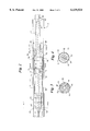
- FIG. 1 shows a side-elevational view of an inventive catheter.
- FIG. 2 shows a schematic of the canister region of the catheter of FIG. 1, the catheter residing in a guide catheter.
- FIG. 3 is a schematic of a transverse cross-sectional view of the catheter shown in FIG. 2 taken along the lines 3--3.
- FIG. 4 is a schematic of a transverse cross-sectional view of the catheter shown in FIG. 2 taken along the lines 4--4.
- FIG. 5 is a schematic perspective view of the stent canister.
- FIG. 6 is a transverse cross-sectional view of the catheter shown in FIG. 2 taken along the lines 6--6.
- FIG. 7 is an enlarged view of region 7 in FIG. 1.
- FIG. 8 is a schematic side-elevational view of a rapid exchange version of the inventive catheter.
- FIGS. 1-4 illustrate a perfusion type catheter, shown generally at 10, embodying features of the present invention.
- the catheter 10 generally includes an elongated catheter shaft 14 having proximal 18 and distal 22 ends. Carried within catheter shaft 14 and extending beyond distal end 22 of catheter shaft 14 is an inner tube 26 of greater length than elongated catheter shaft 14. Inner tube 26 has proximal 30 and distal ends 34.
- Inner tube 26 is preferably made of flexible, but incompressible construction such as a polymer encapsulated braid or coil.
- the flexibility of the braid/coil construction allows the catheter to navigate through body lumens and the incompressibility of the braid/coil aids in maintaining the integrity for the catheter and aids in deployment accuracy when the sheath is being retracted during stent release.
- the braid/coil may be comprised of stainless steel encased in a polymer such as Polyimide with an inner layer of Teflon.
- a catheter tip 38 is affixed to distal end 34 of inner tube 26.
- An adhesive such as H.B. Fuller 3507, a urethane adhesive, or the like is suitable.
- Proximal end 42 of sheath 46 is mounted on distal end 22 of catheter shaft 14. The mounting may be accomplished using any suitable adhesive known in the art or through any other suitable means.
- Sheath 46 may be flexible or rigid, and is generally used to retain a stent 36 and protect the vessel wall.
- the retractable sheath is preferably formed of a material which provides tensile strength, but is flexible, such as polyethylene. Sheath 46 further has a distal end 50.
- Sheath 46 extends distally to cover the portion of inner tube 26 extending beyond distal end 22 of catheter shaft 14. Distal end 50 of sheath 46 sealingly abuts catheter tip 38 to form a chamber 54 defined by distal end 22 of catheter shaft 14, sheath 46 and catheter tip 38.
- the proximal end 42 of sheath 46 includes at least one proximal perfusion opening 58.
- Catheter tip 38 includes at least one distal perfusion opening 62 extending from chamber 54 through catheter tip 38 allowing fluid to flow in the at least one distal perfusion opening 62, through chamber 54 and out the at least one proximal perfusion opening 58. Also shown in FIG. 2, although not in FIG. 1, is an optional guide catheter 63.
- a manifold 24 is secured to the proximal end 18 of catheter shaft 14.
- FIGS. 3 and 4 Proximal and distal perfusion openings 58 and 62 are better seen in FIGS. 3 and 4 which present transverse cross-sectional views of the catheter shown in FIG. 2 taken along the lines 3--3 and 4--4 respectively.
- FIG. 3 shows a transverse cross-section through the proximal end of the sheath including four proximal perfusion openings 58 in sheath 46, catheter shaft 14 and inner tube 26
- FIG. 4 shows a transverse cross section through tip 38 including four distal perfusion openings 62 and inner tube 26.
- FIGS. 3 and 4 also show an optional guide catheter 63.
- FIG. 5 shows a perspective view of the inventive catheter, showing distal perfusion openings 62 in tip 38 and proximal perfusion openings 62 in proximal portion of sheath 46.
- the inventive perfusion catheter further comprises a treatment device that may be deployed at a desired bodily location.
- the treatment device is stent 66 mounted over distal end 34 of inner tube 26 and underneath sheath 46.
- One or more optional bumpers 70 may abut stent 66. If present, bumpers 70 may have one or more bumper perfusion openings therein as seen in FIG. 6.
- FIG. 6 shows a transverse cross section of the catheter along line 6--6 including optional guide catheter 63, sheath 46, bumper 70 and inner tube 26 therein.
- Bumper 70 is shown having four bumper perfusion openings 74 therein.
- Bumper 70 may be of polyethylene and is affixed to inner tube 26 by adhesive such as H.B. Fuller 3507 so as to prevent movement of stent 66 in a proximal direction when sheath 46 is retracted.
- the catheter may further comprise one or more marker bands 71 abutting stent 66.
- Marker bands 71 are included to aid in positioning and maybe affixed to inner tube 26 by adhesive such as Loctite 4011.
- Stent 66 may be self-expanding, mechanically expandable or balloon expandable.
- a balloon (not shown) is mounted over inner tube 26 such that at least a portion of the balloon is underneath stent 66.
- the balloon is in fluid communication with an inflation lumen for inflating the balloon.
- a description of an inflation lumen in fluid communication with a balloon may be found in U.S. Pat. No. 5,360,401 to Turnland, incorporated in its entirety herein by reference.
- other types of treatment devices may be used as well such as a fiber optic cable in communication with a radiation source or a balloon for angioplasty.
- proximal end 42 of sheath 46 is shown having a tapered narrowing transition portion 64 with proximal perfusion openings 58 therein, the proximal end of the sheath need not be tapered. In another embodiment, the proximal end of the sheath ends in an endcap having proximal perfusion openings therein.
- the invention contemplates the use of any suitable means known in the art for retracting the sheath.
- elongated catheter shaft 14 comprises a number of sections including an accordion-like collapsible section 72, which may be adhesively or otherwise joined to adjacent segments 76 and 77 of the catheter shaft, as described in U.S. Pat. No. 5,534,007 incorporated herein in its entirety by reference.
- the sheath is withdrawn by pulling on a pull wire (not shown) attached to the sheath.
- the pull wire may take the form of the nitinol retraction wire disclosed in commonly owned U.S. patent application Ser. Nos. 08/941,978 and 08/947,619, the entire contents of which are hereby incorporated by reference.
- the accordion-like section compresses as the sheath, which is attached to the catheter shaft, moves in a proximal direction.
- the perfusion catheter further comprises a pull back mechanism for retracting the sheath.
- the pull back mechanism in this case, is a pull collar 74 assembly having a pull wire 78 attached thereto.
- Pull collar 74 is a ring-shaped member of stainless steel or a radio-opaque substance such as gold affixed to the interior of the sheath by an appropriate adhesive such as Loctite 4011, a cyanoacrylate.
- the pull wire extends to the proximal end of the catheter and is operatively connected to the sheath.
- Other suitable pull back mechanisms include screw-like retraction devices as described in U.S. Pat. No. 5,201,757 to Heyn et al. incorporated herein in its entirety by reference. Any other suitable pull back mechanism, as is known in the art, may also be used.
- the perfusion catheter may further comprise a balloon mounted thereon, underneath the stent as described in U.S. Pat. No. 5,360,401 to Turnland.
- the tapered narrowing transition portion of the sheath and more generally, the proximal end of the sheath may be slidably sealed to the distal end of the catheter shaft as described in U.S. patent application Ser. No. 09/071,484 filed May 1, 1998, and U.S.application Ser. No. 08/722,834 filed Sep. 27 1996, both of which are incorporated in their entirety herein by reference
- Catheter 10 may further include other lumen as well such as a guidewire lumen.
- the inventive catheter may be self-priming when inserted in a lumen and exposed to arterial blood pressure and flow. As shown in FIG. 2, blood entering distal perfusion openings 62 flows through chamber 54 in a proximal direction as indicated by the arrows, through the bumper perfusion openings and forces air out of the chamber through proximal perfusion openings 58.
- the full length sheath has a region of enlarged diameter corresponding to the region of the stent chamber and a region of reduced diameter proximal to the region on enlarged diameter.
- the perfusion holes are present on the distal and proximal ends of the region of enlarged diameter.
- a seal may be present either at the proximal end of the region of enlarged diameter or just proximal to the region to prevent blood from flowing along the entire length of the proximal sheath. Such a seal may extend from the sheath to the inner tube.
- the invention pertains to a variety of catheters including over the wire catheters, rapid exchange catheters and fixed wire catheters.
- a schematic illustration of a rapid exchange version of the inventive catheter is shown in FIG. 8.
- a retractable sheath 46 is present at the distal end of catheter shaft 14.
- Catheter shaft 14 further has a guide wire port 67 proximal to retractable sheath 46 through which guide wire 69 enters the catheter.
- Guide wire 69 is carried within inner tube 26 which extends from guide wire port 67 to distal tip 38.
- Distal perfusion holes 62 are present in tip 38.
- Inner tube 26 optionally has a balloon 71 mounted thereon.
- Optional balloon 71 is in fluid communication with inflation lumen 73 which extends to the proximal end of the catheter.
- Stent 66 is mounted over the distal end of inner tube 26 and contained by retractable sheath 46.
- Retractable sheath 46 has proximal perfusion holes 58 so as to allow for perfusion across chamber 54.
- Attached to the proximal end of retractable sheath 46 is a pull collar 74 assembly having a pull wire 78 attached thereto.
- Pull wire 78 extends proximally to a manifold (not shown).
- the usable length of the perfusion catheter is approximately 135 cm. For a rapid-exchange catheter the distance from where the guide wire accesses the inner tube to the distal tip will be approximately 5 cm to 35 cm.
- a fixed wire version of the inventive catheter may be made by modifying an over-the-wire version of the catheter such that the guide wire is actually fixed to the catheter.
- the fixed wire catheter disclosed in U.S. Pat. No. 5,702,364 to Euteneuer et al. and incorporated herein its entirety by reference may also be used in conjunction with the present invention to produce a fixed wire perfusion catheter.
- Other suitable designs for fixed wire catheters known in the art may also be applied to the inventive catheter so as produce an inventive fixed wire perfusion catheter.
- the invention also pertains to a method of delivering a stent to a desired location in a bodily vessel while maintaining perfusion of the vessel.
- the methods involves the steps of providing an inventive perfusion catheter such as that described above, delivering a stent using the inventive perfusion catheter to the desired bodily location, retracting the sheath on the catheter, deploying the stent, and removing the catheter from the bodily vessel.
- the invention is further directed to a method of delivering a treatment device to a desired location in a bodily vessel while maintaining perfusion of the vessel distal to the desired location comprising the steps of providing an inventive self-priming perfusion catheter, inserting the catheter into a bodily vessel so that air is forced out of the proximal perfusion openings of the catheter chamber as blood flows in through the distal perfusion openings, delivering the treatment device to the desired bodily location, retracting the sheath, deploying the treatment device, and removing the catheter from the bodily vessel.
- catheter 10 may be inserted in a guide catheter and may be advanced over a guidewire into a vessel in a patient in a conventional manner until the treatment device reaches the desired bodily location. Once in position, the guidewire may be removed.
- the guide catheter is constructed and arranged so as to have an inner diameter which is only slightly larger than the largest outer diameter of the perfusion catheter, namely, the outer diameter of the sheath covering the treatment device. Desirably, the smallest guide catheter that will accommodate the inventive perfusion catheter is used.
- FIGS. 3, 4 and 6 has four perfusion openings
- the precise number of openings, the positioning of the openings and the size of the perfusion openings will depend on the specific dimensions of the catheter and the purpose to which the catheter is put. It is desirable that the proximal and distal perfusion openings as well as any bumper perfusion openings be arranged so as to facilitate substantially longitudinal fluid flow through the catheter.
- the perfusion openings may be round, elliptical, rectangular or of other suitable shape as is known in the art.
- inventive perfusion catheter may also be used in other bodily lumens through which fluids flow.
Abstract
Description
Claims (26)
Priority Applications (6)
| Application Number | Priority Date | Filing Date | Title |
|---|---|---|---|
| US09/174,283 US6139524A (en) | 1998-10-16 | 1998-10-16 | Stent delivery system with perfusion |
| DE69913720T DE69913720T2 (en) | 1998-10-16 | 1999-09-24 | PERFUSION CATHETER FOR INSERTING A STENT |
| PCT/US1999/022165 WO2000023139A1 (en) | 1998-10-16 | 1999-09-24 | Stent delivery perfusion catheter |
| JP2000576911A JP2002527211A (en) | 1998-10-16 | 1999-09-24 | Stent delivery perfusion catheter |
| CA002346821A CA2346821A1 (en) | 1998-10-16 | 1999-09-24 | Stent delivery system with perfusion |
| EP99948438A EP1121174B1 (en) | 1998-10-16 | 1999-09-24 | Stent delivery perfusion catheter |
Applications Claiming Priority (1)
| Application Number | Priority Date | Filing Date | Title |
|---|---|---|---|
| US09/174,283 US6139524A (en) | 1998-10-16 | 1998-10-16 | Stent delivery system with perfusion |
Publications (1)
| Publication Number | Publication Date |
|---|---|
| US6139524A true US6139524A (en) | 2000-10-31 |
Family
ID=22635584
Family Applications (1)
| Application Number | Title | Priority Date | Filing Date |
|---|---|---|---|
| US09/174,283 Expired - Lifetime US6139524A (en) | 1998-10-16 | 1998-10-16 | Stent delivery system with perfusion |
Country Status (6)
| Country | Link |
|---|---|
| US (1) | US6139524A (en) |
| EP (1) | EP1121174B1 (en) |
| JP (1) | JP2002527211A (en) |
| CA (1) | CA2346821A1 (en) |
| DE (1) | DE69913720T2 (en) |
| WO (1) | WO2000023139A1 (en) |
Cited By (47)
| Publication number | Priority date | Publication date | Assignee | Title |
|---|---|---|---|---|
| US6884259B2 (en) | 2001-04-11 | 2005-04-26 | Boston Scientific Scimed, Inc. | Multi-length delivery system |
| US20050154439A1 (en) * | 2004-01-08 | 2005-07-14 | Gunderson Richard C. | Medical device delivery systems |
| US20050195789A1 (en) * | 2004-03-02 | 2005-09-08 | Nokia Corporation | Preventing an incorrect synchronization between a received code-modulated signal and a replica code |
| US20060074396A1 (en) * | 2004-09-28 | 2006-04-06 | Medtronic Vascular, Inc. | Stent delivery system |
| US20060229697A1 (en) * | 2005-03-30 | 2006-10-12 | Michael Gerdts | Catheter |
| US20070043381A1 (en) * | 2005-08-19 | 2007-02-22 | Icon Medical Corp. | Medical device deployment instrument |
| US7229431B2 (en) | 2001-11-08 | 2007-06-12 | Russell A. Houser | Rapid exchange catheter with stent deployment, therapeutic infusion, and lesion sampling features |
| US20080109029A1 (en) * | 2006-11-06 | 2008-05-08 | The Regents Of The University Of Michigan | Angioplasty Balloon with Therapeutic/Aspiration Channel |
| US20090198178A1 (en) * | 2007-12-26 | 2009-08-06 | The Regents Of The University Of Michigan | Ostial Stenting System |
| WO2009105044A1 (en) | 2008-02-22 | 2009-08-27 | Agency For Science, Technology And Research (A*Star) | Mesenchymal stem cell particles |
| US7651521B2 (en) | 2004-03-02 | 2010-01-26 | Cardiomind, Inc. | Corewire actuated delivery system with fixed distal stent-carrying extension |
| US7699884B2 (en) | 2006-03-22 | 2010-04-20 | Cardiomind, Inc. | Method of stenting with minimal diameter guided delivery systems |
| US7771463B2 (en) | 2003-03-26 | 2010-08-10 | Ton Dai T | Twist-down implant delivery technologies |
| US7785361B2 (en) | 2003-03-26 | 2010-08-31 | Julian Nikolchev | Implant delivery technologies |
| US7862602B2 (en) | 2005-11-02 | 2011-01-04 | Biosensors International Group, Ltd | Indirect-release electrolytic implant delivery systems |
| WO2011053257A2 (en) | 2009-11-02 | 2011-05-05 | Agency For Science, Technology And Research (A*Star) | Methods of monitoring cellular states |
| US20110166497A1 (en) * | 2007-07-18 | 2011-07-07 | Enrique Criado | Methods and systems for establishing retrograde carotid arterial blood flow |
| US8016869B2 (en) | 2003-03-26 | 2011-09-13 | Biosensors International Group, Ltd. | Guidewire-less stent delivery methods |
| US20120006999A1 (en) * | 2006-06-01 | 2012-01-12 | Abbott Cardiovascular Systems Inc. | System For Radiation Sterilization Of Medical Devices |
| WO2012108842A1 (en) | 2011-02-11 | 2012-08-16 | Agency For Science, Technology And Research | Methods of detecting therapeutic exosomes |
| EP2617428A1 (en) | 2006-08-15 | 2013-07-24 | Agency for Science, Technology and Research | Mesenchymal stem cell conditioned medium |
| US8652193B2 (en) | 2005-05-09 | 2014-02-18 | Angiomed Gmbh & Co. Medizintechnik Kg | Implant delivery device |
| US8657870B2 (en) | 2009-06-26 | 2014-02-25 | Biosensors International Group, Ltd. | Implant delivery apparatus and methods with electrolytic release |
| US8784468B2 (en) | 2010-11-17 | 2014-07-22 | Boston Scientific Scimed, Inc. | Stent delivery systems and locking members for use with stent delivery systems |
| KR101423745B1 (en) * | 2012-07-26 | 2014-08-04 | 한국과학기술원 | Method for prognosing sensitivities for rheumatoid arthritis |
| US8858490B2 (en) | 2007-07-18 | 2014-10-14 | Silk Road Medical, Inc. | Systems and methods for treating a carotid artery |
| US9084692B2 (en) | 2010-11-17 | 2015-07-21 | Boston Scientific Scimed, Inc. | Stent delivery system |
| US9126018B1 (en) | 2014-09-04 | 2015-09-08 | Silk Road Medical, Inc. | Methods and devices for transcarotid access |
| US9220619B2 (en) | 2010-11-17 | 2015-12-29 | Boston Scientific Scimed, Inc. | Stent delivery system |
| US9265512B2 (en) | 2013-12-23 | 2016-02-23 | Silk Road Medical, Inc. | Transcarotid neurovascular catheter |
| WO2016043654A1 (en) | 2014-09-15 | 2016-03-24 | Agency For Science, Technology And Research | Methods of treating graft versus host disease (gvhd) or epidermolysis bullosa (eb) with exosomes |
| US9566149B2 (en) | 2010-11-16 | 2017-02-14 | W. L. Gore & Associates, Inc. | Devices and methods for in situ fenestration of a stent-graft at the site of a branch vessel |
| US9669191B2 (en) | 2008-02-05 | 2017-06-06 | Silk Road Medical, Inc. | Interventional catheter system and methods |
| US10058443B2 (en) | 2011-11-02 | 2018-08-28 | Boston Scientific Scimed, Inc. | Stent delivery systems and methods for use |
| US10159587B2 (en) | 2015-01-16 | 2018-12-25 | Boston Scientific Scimed, Inc. | Medical device delivery system with force reduction member |
| US10226563B2 (en) | 2008-12-23 | 2019-03-12 | Silk Road Medical, Inc. | Methods and systems for treatment of acute ischemic stroke |
| US10327790B2 (en) | 2011-08-05 | 2019-06-25 | Route 92 Medical, Inc. | Methods and systems for treatment of acute ischemic stroke |
| WO2019238952A1 (en) | 2018-06-15 | 2019-12-19 | Marinas Pardo Luis | Pharmaceutical composition for dermatology and uses thereof |
| US10779855B2 (en) | 2011-08-05 | 2020-09-22 | Route 92 Medical, Inc. | Methods and systems for treatment of acute ischemic stroke |
| US11013627B2 (en) | 2018-01-10 | 2021-05-25 | Boston Scientific Scimed, Inc. | Stent delivery system with displaceable deployment mechanism |
| US11027104B2 (en) | 2014-09-04 | 2021-06-08 | Silk Road Medical, Inc. | Methods and devices for transcarotid access |
| US11065137B2 (en) | 2016-02-26 | 2021-07-20 | Boston Scientific Scimed, Inc. | Stent delivery systems with a reduced profile |
| US11229770B2 (en) | 2018-05-17 | 2022-01-25 | Route 92 Medical, Inc. | Aspiration catheter systems and methods of use |
| US11351048B2 (en) | 2015-11-16 | 2022-06-07 | Boston Scientific Scimed, Inc. | Stent delivery systems with a reinforced deployment sheath |
| US11602447B2 (en) | 2019-02-13 | 2023-03-14 | Boston Scientific Scimed Inc. | Stent delivery systems |
| US11633571B2 (en) | 2015-02-04 | 2023-04-25 | Route 92 Medical, Inc. | Rapid aspiration thrombectomy system and method |
| US11793529B2 (en) | 2015-02-04 | 2023-10-24 | Route 92 Medical, Inc. | Aspiration catheter systems and methods of use |
Families Citing this family (6)
| Publication number | Priority date | Publication date | Assignee | Title |
|---|---|---|---|---|
| WO2012122048A1 (en) * | 2011-03-04 | 2012-09-13 | Stryker Corporation | Stent delivery system |
| CN107296638B (en) | 2014-09-10 | 2020-06-16 | 泰利福生命科学有限公司 | Perfusion catheter and related methods |
| US10729454B2 (en) | 2014-09-10 | 2020-08-04 | Teleflex Life Sciences Limited | Guidewire capture |
| US10245050B2 (en) | 2016-09-30 | 2019-04-02 | Teleflex Innovations S.À.R.L. | Methods for facilitating revascularization of occlusion |
| US11027102B2 (en) | 2018-07-20 | 2021-06-08 | Teleflex Life Sciences Limited | Perfusion catheters and related methods |
| WO2020037064A1 (en) | 2018-08-16 | 2020-02-20 | Teleflex Life Sciences Limited | Eluting perfusion catheters |
Citations (12)
| Publication number | Priority date | Publication date | Assignee | Title |
|---|---|---|---|---|
| US4661094A (en) * | 1985-05-03 | 1987-04-28 | Advanced Cardiovascular Systems | Perfusion catheter and method |
| US4732152A (en) * | 1984-12-05 | 1988-03-22 | Medinvent S.A. | Device for implantation and a method of implantation in a vessel using such device |
| US5201757A (en) * | 1992-04-03 | 1993-04-13 | Schneider (Usa) Inc. | Medial region deployment of radially self-expanding stents |
| US5360401A (en) * | 1993-02-18 | 1994-11-01 | Advanced Cardiovascular Systems, Inc. | Catheter for stent delivery |
| US5368566A (en) * | 1992-04-29 | 1994-11-29 | Cardiovascular Dynamics, Inc. | Delivery and temporary stent catheter having a reinforced perfusion lumen |
| US5534007A (en) * | 1995-05-18 | 1996-07-09 | Scimed Life Systems, Inc. | Stent deployment catheter with collapsible sheath |
| US5573509A (en) * | 1994-11-22 | 1996-11-12 | Advanced Cardiovascular Systems, Inc. | Catheter with an expandable perfusion slit |
| US5632754A (en) * | 1994-12-23 | 1997-05-27 | Devices For Vascular Intervention | Universal catheter with interchangeable work element |
| US5690643A (en) * | 1996-02-20 | 1997-11-25 | Leocor, Incorporated | Stent delivery system |
| US5700243A (en) * | 1992-10-30 | 1997-12-23 | Pdt Systems, Inc. | Balloon perfusion catheter |
| US5702364A (en) * | 1988-02-29 | 1997-12-30 | Scimed Life Systems Inc | Fixed-wire dilatation balloon catheter |
| US5891154A (en) * | 1997-05-06 | 1999-04-06 | Advanced Cardiovascular System, Inc. | Passive perfusion stent delivery system |
Family Cites Families (5)
| Publication number | Priority date | Publication date | Assignee | Title |
|---|---|---|---|---|
| FR2686256A1 (en) * | 1992-01-17 | 1993-07-23 | Nycomed Ingenor Sa Lab | Dilation catheter |
| US5569184A (en) * | 1992-04-29 | 1996-10-29 | Cardiovascular Dynamics, Inc. | Delivery and balloon dilatation catheter and method of using |
| US5336178A (en) * | 1992-11-02 | 1994-08-09 | Localmed, Inc. | Intravascular catheter with infusion array |
| US5772669A (en) * | 1996-09-27 | 1998-06-30 | Scimed Life Systems, Inc. | Stent deployment catheter with retractable sheath |
| US7148498B1 (en) | 2004-06-25 | 2006-12-12 | Henkel Corporation | Externally controlled electromagnetic energy spot curing system |
-
1998
- 1998-10-16 US US09/174,283 patent/US6139524A/en not_active Expired - Lifetime
-
1999
- 1999-09-24 DE DE69913720T patent/DE69913720T2/en not_active Expired - Lifetime
- 1999-09-24 WO PCT/US1999/022165 patent/WO2000023139A1/en active IP Right Grant
- 1999-09-24 JP JP2000576911A patent/JP2002527211A/en active Pending
- 1999-09-24 CA CA002346821A patent/CA2346821A1/en not_active Abandoned
- 1999-09-24 EP EP99948438A patent/EP1121174B1/en not_active Expired - Lifetime
Patent Citations (12)
| Publication number | Priority date | Publication date | Assignee | Title |
|---|---|---|---|---|
| US4732152A (en) * | 1984-12-05 | 1988-03-22 | Medinvent S.A. | Device for implantation and a method of implantation in a vessel using such device |
| US4661094A (en) * | 1985-05-03 | 1987-04-28 | Advanced Cardiovascular Systems | Perfusion catheter and method |
| US5702364A (en) * | 1988-02-29 | 1997-12-30 | Scimed Life Systems Inc | Fixed-wire dilatation balloon catheter |
| US5201757A (en) * | 1992-04-03 | 1993-04-13 | Schneider (Usa) Inc. | Medial region deployment of radially self-expanding stents |
| US5368566A (en) * | 1992-04-29 | 1994-11-29 | Cardiovascular Dynamics, Inc. | Delivery and temporary stent catheter having a reinforced perfusion lumen |
| US5700243A (en) * | 1992-10-30 | 1997-12-23 | Pdt Systems, Inc. | Balloon perfusion catheter |
| US5360401A (en) * | 1993-02-18 | 1994-11-01 | Advanced Cardiovascular Systems, Inc. | Catheter for stent delivery |
| US5573509A (en) * | 1994-11-22 | 1996-11-12 | Advanced Cardiovascular Systems, Inc. | Catheter with an expandable perfusion slit |
| US5632754A (en) * | 1994-12-23 | 1997-05-27 | Devices For Vascular Intervention | Universal catheter with interchangeable work element |
| US5534007A (en) * | 1995-05-18 | 1996-07-09 | Scimed Life Systems, Inc. | Stent deployment catheter with collapsible sheath |
| US5690643A (en) * | 1996-02-20 | 1997-11-25 | Leocor, Incorporated | Stent delivery system |
| US5891154A (en) * | 1997-05-06 | 1999-04-06 | Advanced Cardiovascular System, Inc. | Passive perfusion stent delivery system |
Cited By (108)
| Publication number | Priority date | Publication date | Assignee | Title |
|---|---|---|---|---|
| US6884259B2 (en) | 2001-04-11 | 2005-04-26 | Boston Scientific Scimed, Inc. | Multi-length delivery system |
| US7229431B2 (en) | 2001-11-08 | 2007-06-12 | Russell A. Houser | Rapid exchange catheter with stent deployment, therapeutic infusion, and lesion sampling features |
| US8016869B2 (en) | 2003-03-26 | 2011-09-13 | Biosensors International Group, Ltd. | Guidewire-less stent delivery methods |
| US7785361B2 (en) | 2003-03-26 | 2010-08-31 | Julian Nikolchev | Implant delivery technologies |
| US7771463B2 (en) | 2003-03-26 | 2010-08-10 | Ton Dai T | Twist-down implant delivery technologies |
| US20050154439A1 (en) * | 2004-01-08 | 2005-07-14 | Gunderson Richard C. | Medical device delivery systems |
| US8152818B2 (en) | 2004-01-08 | 2012-04-10 | Boston Scientific Scimed, Inc. | Medical device delivery systems |
| US7651521B2 (en) | 2004-03-02 | 2010-01-26 | Cardiomind, Inc. | Corewire actuated delivery system with fixed distal stent-carrying extension |
| US20050195789A1 (en) * | 2004-03-02 | 2005-09-08 | Nokia Corporation | Preventing an incorrect synchronization between a received code-modulated signal and a replica code |
| US20060074396A1 (en) * | 2004-09-28 | 2006-04-06 | Medtronic Vascular, Inc. | Stent delivery system |
| US7740652B2 (en) | 2005-03-30 | 2010-06-22 | Boston Scientific Scimed, Inc. | Catheter |
| US8685076B2 (en) | 2005-03-30 | 2014-04-01 | Boston Scientific Scimed, Inc. | Catheter |
| US20060229697A1 (en) * | 2005-03-30 | 2006-10-12 | Michael Gerdts | Catheter |
| US9393141B2 (en) | 2005-03-30 | 2016-07-19 | Boston Scientific Scimed, Inc. | Catheter |
| US20100256727A1 (en) * | 2005-03-30 | 2010-10-07 | Boston Scientific Scimed, Inc. | Catheter |
| US8652193B2 (en) | 2005-05-09 | 2014-02-18 | Angiomed Gmbh & Co. Medizintechnik Kg | Implant delivery device |
| US20070043381A1 (en) * | 2005-08-19 | 2007-02-22 | Icon Medical Corp. | Medical device deployment instrument |
| US8900285B2 (en) | 2005-11-02 | 2014-12-02 | Biosensors International Group, Ltd. | Covering electrolytic restraint implant delivery systems |
| US7862602B2 (en) | 2005-11-02 | 2011-01-04 | Biosensors International Group, Ltd | Indirect-release electrolytic implant delivery systems |
| US8579954B2 (en) | 2005-11-02 | 2013-11-12 | Biosensors International Group, Ltd. | Untwisting restraint implant delivery system |
| US8974509B2 (en) | 2005-11-02 | 2015-03-10 | Biosensors International Group, Ltd. | Pass-through restraint electrolytic implant delivery systems |
| US8273116B2 (en) | 2005-11-02 | 2012-09-25 | Biosensors International Group, Ltd. | Indirect-release electrolytic implant delivery systems |
| US7699884B2 (en) | 2006-03-22 | 2010-04-20 | Cardiomind, Inc. | Method of stenting with minimal diameter guided delivery systems |
| US20120006999A1 (en) * | 2006-06-01 | 2012-01-12 | Abbott Cardiovascular Systems Inc. | System For Radiation Sterilization Of Medical Devices |
| US8471229B2 (en) * | 2006-06-01 | 2013-06-25 | Abbott Cardiovascular Systems Inc. | System for radiation sterilization of medical devices |
| EP2617428A1 (en) | 2006-08-15 | 2013-07-24 | Agency for Science, Technology and Research | Mesenchymal stem cell conditioned medium |
| US20110098798A1 (en) * | 2006-11-06 | 2011-04-28 | The Regents Of The University Of Michigan | Angioplasty Balloon with Therapeutic/Aspiration Channel |
| US20080109029A1 (en) * | 2006-11-06 | 2008-05-08 | The Regents Of The University Of Michigan | Angioplasty Balloon with Therapeutic/Aspiration Channel |
| US8267953B2 (en) | 2006-11-06 | 2012-09-18 | The Regents Of The University Of Michigan | Angioplasty balloon with therapeutic/aspiration channel |
| US7862576B2 (en) | 2006-11-06 | 2011-01-04 | The Regents Of The University Of Michigan | Angioplasty balloon with therapeutic/aspiration channel |
| US10286139B2 (en) | 2007-07-18 | 2019-05-14 | Silk Road Medical, Inc. | Methods and systems for establishing retrograde carotid arterial blood flow |
| US10543307B2 (en) | 2007-07-18 | 2020-01-28 | Silk Road Medical, Inc. | Methods and systems for establishing retrograde carotid arterial blood flow |
| US9833555B2 (en) | 2007-07-18 | 2017-12-05 | Silk Road Medical, Inc. | Methods and systems for establishing retrograde carotid arterial blood flow |
| US20110166497A1 (en) * | 2007-07-18 | 2011-07-07 | Enrique Criado | Methods and systems for establishing retrograde carotid arterial blood flow |
| US8740834B2 (en) | 2007-07-18 | 2014-06-03 | Silk Road Medical, Inc. | Methods and systems for establishing retrograde carotid arterial blood flow |
| US8784355B2 (en) | 2007-07-18 | 2014-07-22 | Silk Road Medical, Inc. | Methods and systems for establishing retrograde carotid arterial blood flow |
| US9655755B2 (en) | 2007-07-18 | 2017-05-23 | Silk Road Medical, Inc. | Systems and methods for treating a carotid artery |
| US11364332B2 (en) | 2007-07-18 | 2022-06-21 | Silk Road Medical, Inc. | Methods and systems for establishing retrograde carotid arterial blood flow |
| US8858490B2 (en) | 2007-07-18 | 2014-10-14 | Silk Road Medical, Inc. | Systems and methods for treating a carotid artery |
| US9789242B2 (en) | 2007-07-18 | 2017-10-17 | Silk Road Medical, Inc. | Methods and systems for establishing retrograde carotid arterial blood flow |
| US10085864B2 (en) | 2007-07-18 | 2018-10-02 | Silk Road Medical, Inc. | Systems and methods for treating a carotid artery |
| US9011364B2 (en) | 2007-07-18 | 2015-04-21 | Silk Road Medical, Inc. | Methods and systems for establishing retrograde carotid arterial blood flow |
| US10426885B2 (en) | 2007-07-18 | 2019-10-01 | Silk Road Medical, Inc. | Methods and systems for establishing retrograde carotid arterial blood flow |
| US10952882B2 (en) | 2007-07-18 | 2021-03-23 | Silk Road Medical, Inc. | Systems and methods for treating a carotid artery |
| US10709832B2 (en) | 2007-07-18 | 2020-07-14 | Silk Road Medical, Inc. | Methods and systems for establishing retrograde carotid arterial blood flow |
| US10485917B2 (en) | 2007-07-18 | 2019-11-26 | Silk Road Medical, Inc. | Methods and systems for establishing retrograde carotid arterial blood flow |
| US9259215B2 (en) | 2007-07-18 | 2016-02-16 | Silk Road Medical, Inc. | Systems and methods for treating a carotid artery |
| US20090198178A1 (en) * | 2007-12-26 | 2009-08-06 | The Regents Of The University Of Michigan | Ostial Stenting System |
| US8287585B2 (en) | 2007-12-26 | 2012-10-16 | The Regents Of The University Of Michigan | Ostial stenting system |
| US9737695B2 (en) | 2007-12-26 | 2017-08-22 | The Regents Of The University Of Michigan | Ostial stenting system |
| US10226598B2 (en) | 2008-02-05 | 2019-03-12 | Silk Road Medical, Inc. | Interventional catheter system and methods |
| US11364369B2 (en) | 2008-02-05 | 2022-06-21 | Silk Road Medical, Inc. | Interventional catheter system and methods |
| US9669191B2 (en) | 2008-02-05 | 2017-06-06 | Silk Road Medical, Inc. | Interventional catheter system and methods |
| WO2009105044A1 (en) | 2008-02-22 | 2009-08-27 | Agency For Science, Technology And Research (A*Star) | Mesenchymal stem cell particles |
| US11103627B2 (en) | 2008-12-23 | 2021-08-31 | Silk Road Medical, Inc. | Methods and systems for treatment of acute ischemic stroke |
| US11654222B2 (en) | 2008-12-23 | 2023-05-23 | Silk Road Medical, Inc. | Methods and systems for treatment of acute ischemic stroke |
| US10226563B2 (en) | 2008-12-23 | 2019-03-12 | Silk Road Medical, Inc. | Methods and systems for treatment of acute ischemic stroke |
| US8657870B2 (en) | 2009-06-26 | 2014-02-25 | Biosensors International Group, Ltd. | Implant delivery apparatus and methods with electrolytic release |
| WO2011053257A2 (en) | 2009-11-02 | 2011-05-05 | Agency For Science, Technology And Research (A*Star) | Methods of monitoring cellular states |
| US9566149B2 (en) | 2010-11-16 | 2017-02-14 | W. L. Gore & Associates, Inc. | Devices and methods for in situ fenestration of a stent-graft at the site of a branch vessel |
| US8784468B2 (en) | 2010-11-17 | 2014-07-22 | Boston Scientific Scimed, Inc. | Stent delivery systems and locking members for use with stent delivery systems |
| US9220619B2 (en) | 2010-11-17 | 2015-12-29 | Boston Scientific Scimed, Inc. | Stent delivery system |
| US9974679B2 (en) | 2010-11-17 | 2018-05-22 | Boston Scientific Scimed, Inc. | Stent delivery system |
| US9084692B2 (en) | 2010-11-17 | 2015-07-21 | Boston Scientific Scimed, Inc. | Stent delivery system |
| WO2012108842A1 (en) | 2011-02-11 | 2012-08-16 | Agency For Science, Technology And Research | Methods of detecting therapeutic exosomes |
| EP3151011A1 (en) | 2011-02-11 | 2017-04-05 | Agency For Science, Technology And Research | Methods of detecting therapeutic exosomes |
| US10646239B2 (en) | 2011-08-05 | 2020-05-12 | Route 92 Medical, Inc. | Methods and systems for treatment of acute ischemic stroke |
| US10779855B2 (en) | 2011-08-05 | 2020-09-22 | Route 92 Medical, Inc. | Methods and systems for treatment of acute ischemic stroke |
| US10743893B2 (en) | 2011-08-05 | 2020-08-18 | Route 92 Medical, Inc. | Methods and systems for treatment of acute ischemic stroke |
| US10327790B2 (en) | 2011-08-05 | 2019-06-25 | Route 92 Medical, Inc. | Methods and systems for treatment of acute ischemic stroke |
| US10722251B2 (en) | 2011-08-05 | 2020-07-28 | Route 92 Medical, Inc. | Methods and systems for treatment of acute ischemic stroke |
| US11871944B2 (en) | 2011-08-05 | 2024-01-16 | Route 92 Medical, Inc. | Methods and systems for treatment of acute ischemic stroke |
| US10058443B2 (en) | 2011-11-02 | 2018-08-28 | Boston Scientific Scimed, Inc. | Stent delivery systems and methods for use |
| KR101423745B1 (en) * | 2012-07-26 | 2014-08-04 | 한국과학기술원 | Method for prognosing sensitivities for rheumatoid arthritis |
| US10384034B2 (en) | 2013-12-23 | 2019-08-20 | Silk Road Medical, Inc. | Transcarotid neurovascular catheter |
| US9265512B2 (en) | 2013-12-23 | 2016-02-23 | Silk Road Medical, Inc. | Transcarotid neurovascular catheter |
| US9861783B2 (en) | 2013-12-23 | 2018-01-09 | Silk Road Medical, Inc. | Transcarotid neurovascular catheter |
| US11534575B2 (en) | 2013-12-23 | 2022-12-27 | Route 92 Medical, Inc. | Methods and systems for treatment of acute ischemic stroke |
| US10569049B2 (en) | 2013-12-23 | 2020-02-25 | Route 92 Medical, Inc. | Methods and systems for treatment of acute ischemic stroke |
| US10471233B2 (en) | 2013-12-23 | 2019-11-12 | Route 92 Medical, Inc. | Methods and systems for treatment of acute ischemic stroke |
| US10213582B2 (en) | 2013-12-23 | 2019-02-26 | Route 92 Medical, Inc. | Methods and systems for treatment of acute ischemic stroke |
| US11318282B2 (en) | 2013-12-23 | 2022-05-03 | Route 92 Medical, Inc. | Methods and systems for treatment of acute ischemic stroke |
| US9561345B2 (en) | 2013-12-23 | 2017-02-07 | Route 92 Medical, Inc. | Methods and systems for treatment of acute ischemic stroke |
| US9492637B2 (en) | 2013-12-23 | 2016-11-15 | Silk Road Medical, Inc. | Transcarotid neurovascular catheter |
| US11291799B2 (en) | 2013-12-23 | 2022-04-05 | Silk Road Medical, Inc. | Transcarotid neurovascular catheter |
| US10864351B2 (en) | 2013-12-23 | 2020-12-15 | Route 92 Medical, Inc. | Methods and systems for treatment of acute ischemic stroke |
| US9399118B2 (en) | 2014-09-04 | 2016-07-26 | Silk Road Medical, Inc. | Methods and devices for transcarotid access |
| US11027104B2 (en) | 2014-09-04 | 2021-06-08 | Silk Road Medical, Inc. | Methods and devices for transcarotid access |
| US11759613B2 (en) | 2014-09-04 | 2023-09-19 | Silk Road Medical, Inc. | Methods and devices for transcarotid access |
| US10039906B2 (en) | 2014-09-04 | 2018-08-07 | Silk Road Medical, Inc. | Methods and devices for transcarotid access |
| US9241699B1 (en) | 2014-09-04 | 2016-01-26 | Silk Road Medical, Inc. | Methods and devices for transcarotid access |
| US9126018B1 (en) | 2014-09-04 | 2015-09-08 | Silk Road Medical, Inc. | Methods and devices for transcarotid access |
| US9662480B2 (en) | 2014-09-04 | 2017-05-30 | Silk Road Medical, Inc. | Methods and devices for transcarotid access |
| US10864357B2 (en) | 2014-09-04 | 2020-12-15 | Silk Road Medical, Inc. | Methods and devices for transcarotid access |
| WO2016043654A1 (en) | 2014-09-15 | 2016-03-24 | Agency For Science, Technology And Research | Methods of treating graft versus host disease (gvhd) or epidermolysis bullosa (eb) with exosomes |
| US10159587B2 (en) | 2015-01-16 | 2018-12-25 | Boston Scientific Scimed, Inc. | Medical device delivery system with force reduction member |
| US11806032B2 (en) | 2015-02-04 | 2023-11-07 | Route 92 Medical, Inc. | Aspiration catheter systems and methods of use |
| US11633571B2 (en) | 2015-02-04 | 2023-04-25 | Route 92 Medical, Inc. | Rapid aspiration thrombectomy system and method |
| US11793529B2 (en) | 2015-02-04 | 2023-10-24 | Route 92 Medical, Inc. | Aspiration catheter systems and methods of use |
| US11351048B2 (en) | 2015-11-16 | 2022-06-07 | Boston Scientific Scimed, Inc. | Stent delivery systems with a reinforced deployment sheath |
| US11065137B2 (en) | 2016-02-26 | 2021-07-20 | Boston Scientific Scimed, Inc. | Stent delivery systems with a reduced profile |
| US11013627B2 (en) | 2018-01-10 | 2021-05-25 | Boston Scientific Scimed, Inc. | Stent delivery system with displaceable deployment mechanism |
| US11229770B2 (en) | 2018-05-17 | 2022-01-25 | Route 92 Medical, Inc. | Aspiration catheter systems and methods of use |
| US11607523B2 (en) | 2018-05-17 | 2023-03-21 | Route 92 Medical, Inc. | Aspiration catheter systems and methods of use |
| US11925770B2 (en) | 2018-05-17 | 2024-03-12 | Route 92 Medical, Inc. | Aspiration catheter systems and methods of use |
| EP3875097A1 (en) | 2018-06-15 | 2021-09-08 | Mariñas Pardo, Luis | Pharmaceutical composition for dermatology and uses thereof |
| WO2019238952A1 (en) | 2018-06-15 | 2019-12-19 | Marinas Pardo Luis | Pharmaceutical composition for dermatology and uses thereof |
| US11602447B2 (en) | 2019-02-13 | 2023-03-14 | Boston Scientific Scimed Inc. | Stent delivery systems |
Also Published As
| Publication number | Publication date |
|---|---|
| CA2346821A1 (en) | 2000-04-27 |
| EP1121174A1 (en) | 2001-08-08 |
| DE69913720D1 (en) | 2004-01-29 |
| WO2000023139A1 (en) | 2000-04-27 |
| DE69913720T2 (en) | 2004-10-07 |
| EP1121174B1 (en) | 2003-12-17 |
| JP2002527211A (en) | 2002-08-27 |
Similar Documents
| Publication | Publication Date | Title |
|---|---|---|
| US6139524A (en) | Stent delivery system with perfusion | |
| JP3037055B2 (en) | Protective sheath stent delivery system | |
| US8986365B2 (en) | Delivery system with retractable proximal end | |
| EP1006939B1 (en) | Stent deployment catheter with retractable sheath | |
| CA2405386C (en) | Stent delivery means with balloon retraction means | |
| US6458151B1 (en) | Ostial stent positioning device and method | |
| JP2956966B2 (en) | Catheter assembly and stent delivery system | |
| US6391050B1 (en) | Self-expanding stent delivery system | |
| US5534007A (en) | Stent deployment catheter with collapsible sheath | |
| US5980533A (en) | Stent delivery system | |
| US5456667A (en) | Temporary stenting catheter with one-piece expandable segment | |
| US5620417A (en) | Rapid exchange delivery catheter | |
| US7387640B2 (en) | Medical device delivery system | |
| ES2304062T3 (en) | STENT IMPLEMENTATION SYSTEM. | |
| US6139572A (en) | Delivery system for intraluminal vascular grafts | |
| US5662703A (en) | Rolling membrane stent delivery device | |
| US20070282302A1 (en) | Stent Positioning Using Inflation Tube | |
| EP0699451A2 (en) | Catheter | |
| JP2002505148A (en) | Expansion and stent delivery system for lesions at bifurcations | |
| JP2004531289A (en) | Thin-film stent delivery system with improved folding | |
| JPH10277159A (en) | Stent supply catheter system |
Legal Events
| Date | Code | Title | Description |
|---|---|---|---|
| AS | Assignment |
Owner name: SCIMED LIFE SYSTEMS, INC., MINNESOTA Free format text: ASSIGNMENT OF ASSIGNORS INTEREST;ASSIGNOR:KILLION, DOUGLAS P.;REEL/FRAME:009524/0397 Effective date: 19981016 |
|
| STCF | Information on status: patent grant |
Free format text: PATENTED CASE |
|
| FPAY | Fee payment |
Year of fee payment: 4 |
|
| AS | Assignment |
Owner name: BOSTON SCIENTIFIC SCIMED, INC., MINNESOTA Free format text: CHANGE OF NAME;ASSIGNOR:SCIMED LIFE SYSTEMS, INC.;REEL/FRAME:018505/0868 Effective date: 20050101 Owner name: BOSTON SCIENTIFIC SCIMED, INC.,MINNESOTA Free format text: CHANGE OF NAME;ASSIGNOR:SCIMED LIFE SYSTEMS, INC.;REEL/FRAME:018505/0868 Effective date: 20050101 |
|
| FPAY | Fee payment |
Year of fee payment: 8 |
|
| FPAY | Fee payment |
Year of fee payment: 12 |