US6144432A - Reflective liquid crystal display device - Google Patents
Reflective liquid crystal display device Download PDFInfo
- Publication number
- US6144432A US6144432A US09/479,634 US47963400A US6144432A US 6144432 A US6144432 A US 6144432A US 47963400 A US47963400 A US 47963400A US 6144432 A US6144432 A US 6144432A
- Authority
- US
- United States
- Prior art keywords
- liquid crystal
- display device
- crystal display
- layer
- reflective liquid
- Prior art date
- Legal status (The legal status is an assumption and is not a legal conclusion. Google has not performed a legal analysis and makes no representation as to the accuracy of the status listed.)
- Expired - Lifetime
Links
Images

Classifications
-
- G—PHYSICS
- G02—OPTICS
- G02F—OPTICAL DEVICES OR ARRANGEMENTS FOR THE CONTROL OF LIGHT BY MODIFICATION OF THE OPTICAL PROPERTIES OF THE MEDIA OF THE ELEMENTS INVOLVED THEREIN; NON-LINEAR OPTICS; FREQUENCY-CHANGING OF LIGHT; OPTICAL LOGIC ELEMENTS; OPTICAL ANALOGUE/DIGITAL CONVERTERS
- G02F1/00—Devices or arrangements for the control of the intensity, colour, phase, polarisation or direction of light arriving from an independent light source, e.g. switching, gating or modulating; Non-linear optics
- G02F1/01—Devices or arrangements for the control of the intensity, colour, phase, polarisation or direction of light arriving from an independent light source, e.g. switching, gating or modulating; Non-linear optics for the control of the intensity, phase, polarisation or colour
- G02F1/13—Devices or arrangements for the control of the intensity, colour, phase, polarisation or direction of light arriving from an independent light source, e.g. switching, gating or modulating; Non-linear optics for the control of the intensity, phase, polarisation or colour based on liquid crystals, e.g. single liquid crystal display cells
- G02F1/133—Constructional arrangements; Operation of liquid crystal cells; Circuit arrangements
- G02F1/1333—Constructional arrangements; Manufacturing methods
- G02F1/1335—Structural association of cells with optical devices, e.g. polarisers or reflectors
-
- G—PHYSICS
- G02—OPTICS
- G02F—OPTICAL DEVICES OR ARRANGEMENTS FOR THE CONTROL OF LIGHT BY MODIFICATION OF THE OPTICAL PROPERTIES OF THE MEDIA OF THE ELEMENTS INVOLVED THEREIN; NON-LINEAR OPTICS; FREQUENCY-CHANGING OF LIGHT; OPTICAL LOGIC ELEMENTS; OPTICAL ANALOGUE/DIGITAL CONVERTERS
- G02F1/00—Devices or arrangements for the control of the intensity, colour, phase, polarisation or direction of light arriving from an independent light source, e.g. switching, gating or modulating; Non-linear optics
- G02F1/01—Devices or arrangements for the control of the intensity, colour, phase, polarisation or direction of light arriving from an independent light source, e.g. switching, gating or modulating; Non-linear optics for the control of the intensity, phase, polarisation or colour
- G02F1/13—Devices or arrangements for the control of the intensity, colour, phase, polarisation or direction of light arriving from an independent light source, e.g. switching, gating or modulating; Non-linear optics for the control of the intensity, phase, polarisation or colour based on liquid crystals, e.g. single liquid crystal display cells
- G02F1/137—Devices or arrangements for the control of the intensity, colour, phase, polarisation or direction of light arriving from an independent light source, e.g. switching, gating or modulating; Non-linear optics for the control of the intensity, phase, polarisation or colour based on liquid crystals, e.g. single liquid crystal display cells characterised by the electro-optical or magneto-optical effect, e.g. field-induced phase transition, orientation effect, guest-host interaction or dynamic scattering
- G02F1/139—Devices or arrangements for the control of the intensity, colour, phase, polarisation or direction of light arriving from an independent light source, e.g. switching, gating or modulating; Non-linear optics for the control of the intensity, phase, polarisation or colour based on liquid crystals, e.g. single liquid crystal display cells characterised by the electro-optical or magneto-optical effect, e.g. field-induced phase transition, orientation effect, guest-host interaction or dynamic scattering based on orientation effects in which the liquid crystal remains transparent
- G02F1/1396—Devices or arrangements for the control of the intensity, colour, phase, polarisation or direction of light arriving from an independent light source, e.g. switching, gating or modulating; Non-linear optics for the control of the intensity, phase, polarisation or colour based on liquid crystals, e.g. single liquid crystal display cells characterised by the electro-optical or magneto-optical effect, e.g. field-induced phase transition, orientation effect, guest-host interaction or dynamic scattering based on orientation effects in which the liquid crystal remains transparent the liquid crystal being selectively controlled between a twisted state and a non-twisted state, e.g. TN-LC cell
- G02F1/1397—Devices or arrangements for the control of the intensity, colour, phase, polarisation or direction of light arriving from an independent light source, e.g. switching, gating or modulating; Non-linear optics for the control of the intensity, phase, polarisation or colour based on liquid crystals, e.g. single liquid crystal display cells characterised by the electro-optical or magneto-optical effect, e.g. field-induced phase transition, orientation effect, guest-host interaction or dynamic scattering based on orientation effects in which the liquid crystal remains transparent the liquid crystal being selectively controlled between a twisted state and a non-twisted state, e.g. TN-LC cell the twist being substantially higher than 90°, e.g. STN-, SBE-, OMI-LC cells
-
- G—PHYSICS
- G02—OPTICS
- G02F—OPTICAL DEVICES OR ARRANGEMENTS FOR THE CONTROL OF LIGHT BY MODIFICATION OF THE OPTICAL PROPERTIES OF THE MEDIA OF THE ELEMENTS INVOLVED THEREIN; NON-LINEAR OPTICS; FREQUENCY-CHANGING OF LIGHT; OPTICAL LOGIC ELEMENTS; OPTICAL ANALOGUE/DIGITAL CONVERTERS
- G02F1/00—Devices or arrangements for the control of the intensity, colour, phase, polarisation or direction of light arriving from an independent light source, e.g. switching, gating or modulating; Non-linear optics
- G02F1/01—Devices or arrangements for the control of the intensity, colour, phase, polarisation or direction of light arriving from an independent light source, e.g. switching, gating or modulating; Non-linear optics for the control of the intensity, phase, polarisation or colour
- G02F1/13—Devices or arrangements for the control of the intensity, colour, phase, polarisation or direction of light arriving from an independent light source, e.g. switching, gating or modulating; Non-linear optics for the control of the intensity, phase, polarisation or colour based on liquid crystals, e.g. single liquid crystal display cells
- G02F1/133—Constructional arrangements; Operation of liquid crystal cells; Circuit arrangements
- G02F1/1333—Constructional arrangements; Manufacturing methods
- G02F1/1335—Structural association of cells with optical devices, e.g. polarisers or reflectors
- G02F1/13363—Birefringent elements, e.g. for optical compensation
-
- G—PHYSICS
- G02—OPTICS
- G02F—OPTICAL DEVICES OR ARRANGEMENTS FOR THE CONTROL OF LIGHT BY MODIFICATION OF THE OPTICAL PROPERTIES OF THE MEDIA OF THE ELEMENTS INVOLVED THEREIN; NON-LINEAR OPTICS; FREQUENCY-CHANGING OF LIGHT; OPTICAL LOGIC ELEMENTS; OPTICAL ANALOGUE/DIGITAL CONVERTERS
- G02F2203/00—Function characteristic
- G02F2203/02—Function characteristic reflective
Definitions
- the present invention relates to the field of reflective liquid crystal display devices.
- LCDs Liquid crystal display devices
- a LCDs information by driving liquid crystal molecules with a few volts of effective voltage to change the light transmissivity. Because liquid crystal itself is a non-light-emitting substance, a separate light source is required, which demands much more power than the power required for driving the liquid crystal.
- a reflective LCD that utilizes ambient light by providing a reflector underneath the LCD achieves a display device with extremely low power consumption while still exploiting the more advantageous characteristics of liquid crystal. The LCD is thus becoming one of the essential displays used in mobile information terminals.
- a conventional reflective LCD includes a liquid crystal cell and a pair of polarizer films sandwiching the liquid crystal cell.
- the light transmissivity of one sheet of the polarizer film is only about 45%, and its transmissivity to light polarized parallel to the absorption axis of the polarizer film is close to 0%.
- the transmissivity of light polarized perpendicular to the absorption axis is almost 90%.
- a reflective LCD using two sheets of polarizer film light entering the LCD passes through polarizer films four times before exiting the LCD. Accordingly, when non-polarized natural light is incident on the LCD, the overall reflectance or light transmissivity can be calculated as follows, without taking absorption by the color filter into consideration:
- single-polarizer configurations therefore provide up to about 24% improvement ((40.5/32.8) ⁇ 100%-100%) in overall reflectance.
- Japanese Laid-open Patent No. H6-308481 proposes a reflective color LCD utilizing the birefringence of twisted liquid crystal layer in combination with polarizer film, to generate a color display without using color filters.
- FIG. 5 shows the configuration of a conventional reflective LCD including one sheet of polarizer film (polarizer) and a color filter.
- a liquid crystal cell 53 is created by sandwiching a liquid crystal layer 57 between a transparent substrate 54, on which a color filter 55 and transparent electrode 56 are formed, and a bottom substrate 59, on which a specular reflector 58 is formed.
- a retardation film 52, polarizer 51, and forward scattering film 50 are laminated outside this liquid crystal cell to complete the reflective LCD.
- a color filter is used to create a color display in a reflective LCD configuration having two sheets of polarizer film, the reflectance is insufficient to secure the required display brightness. If, to secure the required brightness by increasing the reflectance, the color filter is used in a reflective LCD configuration having a single sheet of polarizer film, creation of an achromatic black and white display may be difficult. Undesired coloring may occur in the conventional configuration. In particular, an achromatic black display with low reflectance may not be achieved.
- the optical characteristics of this type of color display depend to a large degree on the direction of incident light and on the viewing angle. If the reflective LCD having a single polarizer film is influenced to a high degree by viewing angle, its disadvantages are not limited to a narrow viewing angle. More specifically, if the reflectance of a black display increases at certain incident light angles, the optical characteristics may be significantly degraded because controlling the incident light angle in a reflective LCD is much more difficult than for a transmissive LCD.
- the reflective LCD utilizing the birefringent characteristics of a twisted liquid crystal layer and polarizer films to achieve a color display without a color filter can secure practical brightness even through two sheets of polarizer film are used because no color filter is employed.
- this configuration may not be theoretically applicable to multi-grayscale and multi-color display such as a 16-grayscale, 4096-color display because coloring is produced by the birefringence effect. This type may also have low color purity and limited color reproduction range.
- the present invention aims to provide a color or black and white reflective LCD having bright white display, high contrast, good achromatic black and white display, and satisfactory optical characteristics with less dependence on viewing angle by solving the above disadvantages of the conventional reflective LCD.
- a reflective LCD of the present invention comprises a liquid crystal cell in which the liquid crystal layer comprises liquid crystal sealed between a first substrate and a second substrate; a polarizer film disposed on the first substrate side of the liquid crystal cell; two retardation films disposed between the polarizer film and the liquid crystal layer of the liquid crystal cell; one or more scattering films disposed between the polarizer film and the liquid crystal layer; and an optical reflector disposed on the second substrate side of the liquid crystal cell.
- This reflective LCD satisfies the following conditions.
- the twisting angle of liquid crystal is between 220° and 260°.
- the multiple ⁇ nLC ⁇ dLC of birefringence ⁇ nLC of liquid crystal and liquid crystal layer thickness dLC is between 700 nm and 1000 nm.
- the reflective LCD satisfies set of formulae 3-5 or set of formulae 8-10:
- .o slashed.LC the angle of the alignment direction of the molecules of liquid crystal contacting the first substrate
- .o slashed.p the angle of the absorption axis of the polarizer film
- .o slashed.F1 the angle of optical slow axis (angle of extraordinary light refractive index) of the retardation film relatively closer to the liquid crystal cell
- .o slashed.F2 the angle of optical slow axis of the retardation film relatively farther from the liquid crystal cell;
- This configuration offers a reflective LCD achieving achromatic black display with sufficiently low reflectance, achromatic white display with high reflectance, and high contrast.
- Disposing the optical reflector between the second substrate and the liquid crystal and using a metal film containing aluminum or silver as the optical reflector minimizes occurrence of a double image or parallax because the liquid crystal layer contacts the reflection face. This configuration achieves further satisfactory display images, and at the same time, achieves a white display with high reflectance.
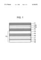
- FIG. 1 is a cross-sectional view of a reflective LCD in accordance with first to third exemplary embodiments of the present invention.
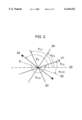
- FIG. 2 is an optical configuration of the reflective LCD in accordance with the first to third exemplary embodiments of the present is invention.
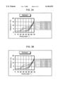
- FIGS. 3A and 3B are graphs showing the percent change in the reflectance of a black display versus rightward and downward changes in viewing angle, respectively, when applying the OFF voltage in the reflective LCD in accordance with the third exemplary embodiment of the present invention.
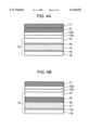
- FIGS. 4A and 4B are cross-sectional views showing examples of the scattering film in different positions in the reflective LCD in accordance with the first to third exemplary embodiments of the present invention.
- FIG. 5 is a sectional view of a configuration of a conventional reflective LCD.
- FIG. 1 shows a cross-sectional view of a reflective LCD in a first exemplary embodiment of the present invention.
- the present exemplary embodiment is a color reflective LCD employing a single polarizer.
- a scattering film 10, retardation films 12a and 12b, and a polarizer film 11 are disposed outside a liquid crystal cell 13.
- Liquid crystal cell 13 includes a liquid crystal layer 17 sandwiched between a bottom substrate 19 on which a specular reflector 18 is formed and a top transparent substrate 14 on which a color filter 15 and transparent electrode 16 are formed.
- Specular reflector 18 corresponds to the specular reflection means in the present invention.
- FIG. 2 shows the optical configuration of the reflective LCD in the first exemplary embodiment, seen from the polarizer film side of the LCD.
- a reference line 20 which is parallel to a face of liquid crystal cell 13, alignment direction 21 of liquid crystal molecules contacting the top transparent substrate 14, alignment direction 22 of the liquid crystal molecules contacting the bottom substrate 19, an optical slow axis direction 23 of a retardation film (1) 12a relatively closer to the liquid crystal cell 13, an optical slow axis direction 24 of a retardation film (2) 12b relatively farther from the liquid crystal cell (relatively closer to the polarizer film 11), and an absorption axis direction 25 of the polarizer film 11 are illustrated in FIG. 2.
- .o slashed.LC0 is the angle of alignment direction 22 of liquid crystal molecules on the bottom substrate 19
- .o slashed.LC is the angle of alignment direction 21 of liquid crystal molecules on the top transparent substrate
- .o slashed.F1 is the angle of the optical slow axis direction 23 of the retardation film (1) 12a
- .o slashed.F2 is the angle of the optical slow axis direction 24 of the retardation film (2) 12b
- .o slashed.p is the angle of absorption axis direction 25 of polarizer film 11.
- ⁇ LC is the twisting angle of liquid crystal twisted from bottom substrate 19 to top transparent substrate 14.
- the twisting direction of liquid crystal from bottom substrate 19 to top substrate 14 is considered to be the positive direction; thus all the angles in FIG. 2 are in the positive direction except for .o slashed.LC0.
- a detailed configuration of the reflective LCD in the first exemplary embodiment is described in the sequence of its manufacturing method below.
- top transparent substrate 14 and bottom substrate 19 Glass substrates are used for top transparent substrate 14 and bottom substrate 19. Red, green, and blue pigment dispersion stripes are photolithographically formed on the top transparent substrate 14 as color filter 15. Then, indium tin oxide (ITO) is formed to create transparent electrode 16 as a pixel electrode. A silver evaporation film is deposited on bottom substrate 19 to form specular reflector 18, which is a metal reflection electrode. After forming, an orientation layer (not illustrated) on the faces of transparent electrode 16 and specular reflector 18 contacting liquid crystal layer 17, alignment is conferred by rubbing.
- ITO indium tin oxide
- Thermosetting sealing resin containing 1.0 wt % of glass fiber is printed on the periphery of top transparent substrate 14. Resin beads with a predetermined diameter are scattered at the ratio of 200 beads/mm 2 on bottom substrate 19; top transparent substrate 14 and bottom substrate 19 are bonded together; and the sealing resin is cured at 150° C.
- Scattering film 10 is pasted on top transparent substrate 14 of liquid crystal cell 13 formed as described above.
- scattering film 10 a material having a transmissivity of 90% for all lights, isotropic scattering characteristics regardless of angle within the film face, and 55% Hayes percentage for exiting light regardless of the angle of the incident light, is employed.
- the Hayes percentage is defined as follows:
- Retardation film (1) 12a and retardation film (2) 12b having a respective predetermined retardation Rfilm(i) as defined by formula 1 are then pasted on scattering film 10 in a way that each optical slow axis creates a respective predetermined angle.
- i is a reference numeral 1 or 2 respectively corresponding to the retardation film (1) 12a and retardation film (2) 12b; nx(i) is the respective refractive index of extraordinary light; ny(i) is the respective refractive index of ordinary light; and d(i) is the respective film thickness for each retardation film.
- polarizer film 11 such as antiglare treated (AG) neutral gray polarizer film (for example, SQ-1852AP by Sumitomo Chemical Co., Ltd.) is pasted in a way that its absorption axis creates a predetermined angle.
- AG antiglare treated neutral gray polarizer film
- the reflective LCD as manufactured above achieves a bright white display, high contrast, achromatic black and white display, and satisfactory optical characteristics with less dependence on viewing angle, when the following conditions are satisfied:
- the twisting angle of liquid crystal (.o slashed.LC0+.o slashed.LC+180°) is between 220° and 260°;
- the configuration satisfying the above conditions minimizes coloring which may occur due to the birefringence effect of the liquid crystal while changing the display from black to white, in particular, while applying the OFF voltage for black display.
- This enables an achromatic black display with low reflectance and achromatic white display with high reflectance to be achieved. Consequently, the present invention offers a color reflective LCD with high contrast and multi-grayscale of high color purity.
- the twisting angle of liquid crystal simple matrix driving influences the duty ratio determining the number of displayable electrodes.
- a larger twisting angle achieves a smaller duty ratio, making it possible to increase the number of electrodes, and in turn, the number of pixels.
- the achievement of a satisfactory display even when driving at a duty ratio of 1/200 or below is confirmed when the twisting angle of liquid (crystal is set to between 220° and 260°.
- the feasibility of driving at a duty ratio of 1/240 or below is confirmed when the twisting angle is set to between 240° and 260°.
- Rfilm(2)-Rfilm(1) 200 nm
- .o slashed.F1-.o slashed.LC 120°
- .o slashed.F2-.o slashed.F1 -60°
- .o slashed.p-.o slashed.F2 -60°
- formula 2 and formulae 3-5 are satisfied.
- the main configuration and the method for manufacturing a reflective LCD in a second exemplary embodiment are the same as those in the first exemplary embodiment. Accordingly, the second exemplary embodiment is described with reference to the sectional configuration as in FIG. 1 and the optical configuration of the reflective LCD in FIG. 2.
- One detail that differs from the first exemplary embodiment is the positional relationship of the optical axes of the retardation film and polarizer film and liquid crystal alignment.
- the reflective LCD manufactured in accordance with the same manufacturing procedures as described in the first exemplary embodiment achieves a bright white display, high contrast, an achromatic black and white display, and satisfactory optical characteristics with less dependence on viewing angle, when the following conditions are satisfied:
- the twisting angle of liquid crystal (.o slashed.LC0+.o slashed.LC+180°) is between 220° and 260°;
- angles .o slashed.LC, .o slashed.p, .o slashed.F1, and .o slashed.F2 satisfy the set of formulae 8-10.
- the configuration satisfying the above conditions minimizes coloring, that may occur due to the birefringence effect of the liquid crystal while changing the display from black to white, in particular, while displaying black during application of the OFF voltage.
- This enables achievement of an achromatic black display with low reflectance and achromatic white display with high reflectance. Consequently, the present invention offers a reflective LCD that achieves color display with high contrast and multi-grayscale of high color purity.
- a third exemplary embodiment of the present invention is described with reference to drawings.
- the main configuration and the manufacturing method in this exemplary embodiment are the same as those of the reflective LCD in the first exemplary embodiment. Accordingly, those which are not specifically described in this exemplary embodiment are the same as those in the first exemplary embodiment. Components given the same numerals as those in the first exemplary embodiment have the same functions as those in the first exemplary embodiment, unless specifically described as being different.
- the third exemplary embodiment is described with reference to the sectional configuration as in FIG. 1 and optical configuration of the reflective LCD in FIG. 2.
- the first and second exemplary embodiments employ a single-axis optically anisotropic film with the optical axis within the film face as the retardation films 12a arid 12b.
- the third exemplary embodiment employs a double-axis anisotropic film also showing the anisotropic refractive index in the direction perpendicular to the film face.
- the reflective LCD manufactured by procedures described in the first exemplary embodiment satisfy the same conditions as the first exemplary embodiment, and further satisfy the next condition, a reflective LCD with satisfactory optical characteristics having even less dependence on viewing angle can be achieved in addition to the benefits of the reflective LCD achieved in the first exemplary embodiment.
- coefficient Qz(i) defined by formula 13 satisfies Formula 14, where the refractive index nz(i) is perpendicular to the respective film face of the retardation film (1) 12a and retardation film (2) 12b.
- the reflective LCD of the present embodiment satisfies the conditions in the first exemplary embodiment and also satisfies formula 14.
- the effect of the reflective LCD in the second exemplary embodiment and also good optical characteristics with even less dependence on viewing angle are achieved when the third exemplary embodiment satisfies the conditions in the second exemplary embodiment and also satisfies formula 14.
- FIGS. 3(a) and 3(b) show the results.
- FIG. 3A shows the changes in percent reflectance versus rightward viewing angle of a black display while applying the OFF voltage.
- FIG. 3B shows the change in percent reflectance versus downward viewing angle of a black display while applying the OFF voltage.
- the reflectance is virtually independent of viewing angle when Qz(2) ⁇ 1.0, and when Qz(1) of the retardation film (1) 12a is 1.0.
- the reflective LCD of the present invention is not limited to the configurations detailed in the first to third exemplary embodiments.
- the present invention includes any reflective LCD that includes a liquid crystal cell in which liquid crystal is sandwiched between first and second substrates, a polarizer film is disposed on the first substrate side of the liquid crystal cell, two sheets of retardation film are disposed between the polarizer film and the liquid crystal layer of the liquid crystal cell, one or more scattering films are disposed between the polarizer film and liquid crystal layer, and an optical reflector is disposed on the second substrate side of the liquid crystal cell, and which satisfies the above conditions.
- silver is used for the specular reflector 18.
- the present invention is not limited to silver.
- a metal reflective electrode containing aluminum as its component may also be employed to achieve the same effects.
- Each exemplary embodiment also employs a material having about 55% Hayes percentage as the scattering film.
- the present invention is not limited to this percentage.
- a scattering film with 80% Hayes percentage is also applicable.
- the exemplary embodiments employ a single layer of scattering film.
- the present invention is not limited to this.
- the same effect is achievable by configuring the scattering film with multiple layers.
- the scattering film in each exemplary embodiment is disposed at the position shown in FIG. 1.
- the present invention is not necessarily limited to this position.
- the same effect is also achievable by disposing scattering film 10 for example, between the polarizer film 11 and retardation film (2) 12b, as shown in FIG. 4A, and between the top transparent substrate 14 and transparent electrode 16, as shown in FIG. 4B.
- the present invention includes any reflective LCD having a liquid crystal twisting angle of between 220° and 260°, the multiple ⁇ nLC ⁇ dLC of birefringence ⁇ nLC of liquid crystal multiplied by liquid crystal layer thickness dLC between 700 nm and 1000 nm, and the relationship described in formula 2 and either set of formulae 3-5 or 8-10; and including a liquid crystal cell in which liquid crystal is sandwiched between first and a second substrates, a polarizer film disposed at the first substrate side of the liquid crystal cell, two sheets of retardation films disposed between the polarizer film and liquid crystal layer of the liquid crystal cell, one or more scattering films disposed between the polarizer film and liquid crystal layer, and an optical reflector disposed at the second substrate side of the liquid crystal cell.
- the present invention offers a reflective LCD having bright white display, high contrast, achromatic black and white display, and satisfactory optical characteristics with less dependence on viewing angle. Accordingly, the present invention achieves significant effects in displaying multi-grayscale color images with high contrast and good color purity in addition to displaying achromatic black with sufficiently low reflectance and achromatic white with high reflectance.
Abstract
Description
(0.9).sup.4 ×50%=32.8%.
(0.9).sup.2 ×50%=40.5%,
Rfilm(i)={nx(i)-ny(i)}·d(i) (1)
|Rfilm(2)-Rfilm(1)|≦200 nm (2)
100°≦.o slashed.F1-.o slashed.LC≦140°(3)
-70°≦.o slashed.F2-.o slashed.F1≦-50°(4)
-70°≦.o slashed.p-.o slashed.F2≦-50°(5)
75°≦.o slashed.F1-.o slashed.LC≦115°(8)
-70°≦.o slashed.F2-.o slashed.F1≦-50°(9)
-40°≦.o slashed.p-.o slashed.F2≦10°(10)
(Hayes percentage)=(Scattering light transmissivity)/(transmissivity of all lights)×100[%].
Rfilm(i)={nx(i)-ny(i)}·d(i) (1)
|Rfilm(2)-Rfilm(1)|≦200 nm (2)
100°≦.o slashed.F1-.o slashed.LC≦140°(3)
-70°≦.o slashed.F2-.o slashed.F1≦-50°(4)
-70°≦.o slashed.p-.o slashed.F2≦-50°(5)
450 nm≦Rfilm(1)≦600 nm (6)
600 nm≦Rfilm(2)≦750 nm (7)
|Rfilm(2)-Rfilm(1)|≦200 nm (2)
75°≦.o slashed.F1-.o slashed.LC≦115°(8)
-70°≦.o slashed.F2-.o slashed.F1≦-50°(9)
-40°≦.o slashed.p-.o slashed.F2≦10°(10)
300 nm≦Rfilm(1)≦500 nm (11)
300 nm≦Rfilm(2)≦500 nm (12)
Qz(i)={nx(i)-nz(i)}/{nx(i)-ny(i)} (13)
0.0≦Qz(i)≦1.0 (14)
Claims (48)
|Rfilm(2)-Rfilm(1)|≦200 nm (2)
100°≦.o slashed.F1-.o slashed.LC≦140°(3)
-70°≦.o slashed.F2-.o slashed.F1≦-50°(4)
-70°≦.o slashed.p-.o slashed.F2≦-50°(5)
75°≦.o slashed.F1-.o slashed.LC≦115°(8)
-70°≦.o slashed.F2-.o slashed.F1≦-50°(9)
-40°≦.o slashed.p-.o slashed.F2≦10°(10)
450 nm≦Rfilm(1)≦600 nm (6)
600 nm≦Rfilm(2)≦750 nm (7).
300 nm≦Rfilm(1)≦500 nm (11)
300 nm≦Rfilm(2)≦500 nm (12).
Qz(i)={nx(i)-nz(i)}/{nx(i)-ny(i)} (13) 0.0≦Qz(i)≦1.0 (14)
Qz(i)={nx(i)-nz(i)}/{nx(i)-ny(i)} (13) 0.0≦Qz(i)≦1.0 (14)
Qz(i)={nx(i)-nz(i)}/{nx(i)-ny(i)} (13) 0.0≦Qz(i)≦1.0 (14)
Qz(i)={nx(i)-nz(i)}/{nx(i)-ny(i)} (13) 0.0≦Qz(i)≦1.0 (14)
Qz(i)={nx(i)-nz(i)}/{nx(i)-ny(i)} (13) 0.0≦Qz(i)≦1.0 (14)
Qz(i)={nx(i)-nz(i)}/{nx(i)-ny(i)} (13) 0.0≦Qz(i)≦1.0 (14)
Applications Claiming Priority (2)
| Application Number | Priority Date | Filing Date | Title |
|---|---|---|---|
| JP11-002345 | 1999-01-07 | ||
| JP234599 | 1999-01-07 |
Publications (1)
| Publication Number | Publication Date |
|---|---|
| US6144432A true US6144432A (en) | 2000-11-07 |
Family
ID=11526704
Family Applications (1)
| Application Number | Title | Priority Date | Filing Date |
|---|---|---|---|
| US09/479,634 Expired - Lifetime US6144432A (en) | 1999-01-07 | 2000-01-07 | Reflective liquid crystal display device |
Country Status (5)
| Country | Link |
|---|---|
| US (1) | US6144432A (en) |
| EP (1) | EP1018663A3 (en) |
| KR (1) | KR20000053405A (en) |
| CN (1) | CN1115587C (en) |
| TW (1) | TW581914B (en) |
Cited By (12)
| Publication number | Priority date | Publication date | Assignee | Title |
|---|---|---|---|---|
| US6307607B1 (en) * | 1999-12-21 | 2001-10-23 | Philips Electronics North America Corporation | Reflective liquid crystal display with integrated compensation for skew angle rotation and birefringence effects |
| US6400437B1 (en) * | 1999-06-30 | 2002-06-04 | Kyocera Corporation | Light semitransmitting type liquid crystal display device |
| US6426785B2 (en) * | 1996-12-05 | 2002-07-30 | Matsushita Electric Industrial Co., Ltd. | Reflective liquid crystal display device |
| US6456347B1 (en) * | 1998-04-28 | 2002-09-24 | Kyocera Corporation | Liquid crystal display |
| US20030063242A1 (en) * | 2001-09-18 | 2003-04-03 | Seiko Epson Corporation | Liquid crystal display device and electronic apparatus |
| US20030086038A1 (en) * | 2001-10-24 | 2003-05-08 | Seiko Epson Corporation | Liquid crystal device and electronic equipment |
| US6567142B1 (en) * | 1999-03-12 | 2003-05-20 | Lg Philips Lcd, Co., Ltd. | Reflective liquid crystal display device including a retardation film of two uniaxial films |
| US6597421B1 (en) * | 1999-12-22 | 2003-07-22 | Matsushita Electric Industrial Co., Ltd. | Reflective liquid crystal display element and image display device using the same |
| US6603521B2 (en) * | 1998-04-10 | 2003-08-05 | Nec Corporation | Reflection type liquid crystal display in which the absorption axis of polarization plate, the optical axis of half phase difference film and optical axis of quarter phase difference film having particular angle to the orientation direction |
| US6665032B1 (en) * | 1999-08-24 | 2003-12-16 | Nec Corporation | Optically compensated bend mode LCD device |
| US20040183969A1 (en) * | 1999-11-02 | 2004-09-23 | Chiyoaki Iijima | Reflective LCD, semitransmitting reflective LCD and electronic device |
| CN100419541C (en) * | 2003-08-14 | 2008-09-17 | Lg化学株式会社 | Complex light-compensation C plate with two or more of C plates different in dispersion ratio value and liquid crystal display using the same |
Families Citing this family (9)
| Publication number | Priority date | Publication date | Assignee | Title |
|---|---|---|---|---|
| KR20040033415A (en) * | 2002-10-14 | 2004-04-28 | 비오이 하이디스 테크놀로지 주식회사 | Reflective mode liquid crystal display device |
| CN100376907C (en) * | 2002-12-20 | 2008-03-26 | 帝人株式会社 | Transparent conductive laminate, touch panel and liquid crystal display unit with touch panel |
| US7969091B2 (en) | 2007-03-02 | 2011-06-28 | Industrial Technology Research Institute | Field-emission apparatus of light source comprising a low pressure gas layer |
| US7936118B2 (en) | 2007-03-02 | 2011-05-03 | Industrial Technology Research Institute | Light source apparatus comprising a stack of low pressure gas filled light emitting panels and backlight module |
| US9435571B2 (en) * | 2008-03-05 | 2016-09-06 | Sheetak Inc. | Method and apparatus for switched thermoelectric cooling of fluids |
| JP5893256B2 (en) * | 2011-03-29 | 2016-03-23 | 株式会社ジャパンディスプレイ | Display device and electronic device |
| CN102914906B (en) * | 2012-10-19 | 2015-02-25 | 京东方科技集团股份有限公司 | Liquid crystal display panel and display device |
| CN109683370B (en) * | 2019-01-28 | 2021-04-27 | Tcl华星光电技术有限公司 | Liquid crystal display |
| CN110262098B (en) * | 2019-07-15 | 2022-02-15 | 昆山龙腾光电股份有限公司 | Liquid crystal display device and driving method |
Citations (6)
| Publication number | Priority date | Publication date | Assignee | Title |
|---|---|---|---|---|
| JPH06308481A (en) * | 1993-04-19 | 1994-11-04 | Casio Comput Co Ltd | Color liquid crystal display device |
| JPH07146469A (en) * | 1993-11-25 | 1995-06-06 | Sharp Corp | Reflection type liquid crystal display device |
| JPH08201802A (en) * | 1995-01-24 | 1996-08-09 | Tatsuo Uchida | Liquid crystal display element of wide visibility angle reflection type using mirror finished surface reflecting board and forward scattering board |
| US5737047A (en) * | 1995-03-27 | 1998-04-07 | Casio Computer Co., Ltd. | Color liquid crystal display device with optical axes of retardation polarization plates set in an opposite direction of twist direction of LC molecules |
| US5798809A (en) * | 1996-08-16 | 1998-08-25 | Fujitsu Limited | Liquid crystal display panel |
| US5995180A (en) * | 1997-07-07 | 1999-11-30 | Sharp Kabushiki Kaisha | Liquid crystal display device having high brightness and high contrast |
-
2000
- 2000-01-06 KR KR1020000000432A patent/KR20000053405A/en not_active Application Discontinuation
- 2000-01-06 TW TW089100164A patent/TW581914B/en not_active IP Right Cessation
- 2000-01-07 EP EP00100346A patent/EP1018663A3/en not_active Ceased
- 2000-01-07 US US09/479,634 patent/US6144432A/en not_active Expired - Lifetime
- 2000-01-07 CN CN00100946A patent/CN1115587C/en not_active Expired - Fee Related
Patent Citations (6)
| Publication number | Priority date | Publication date | Assignee | Title |
|---|---|---|---|---|
| JPH06308481A (en) * | 1993-04-19 | 1994-11-04 | Casio Comput Co Ltd | Color liquid crystal display device |
| JPH07146469A (en) * | 1993-11-25 | 1995-06-06 | Sharp Corp | Reflection type liquid crystal display device |
| JPH08201802A (en) * | 1995-01-24 | 1996-08-09 | Tatsuo Uchida | Liquid crystal display element of wide visibility angle reflection type using mirror finished surface reflecting board and forward scattering board |
| US5737047A (en) * | 1995-03-27 | 1998-04-07 | Casio Computer Co., Ltd. | Color liquid crystal display device with optical axes of retardation polarization plates set in an opposite direction of twist direction of LC molecules |
| US5798809A (en) * | 1996-08-16 | 1998-08-25 | Fujitsu Limited | Liquid crystal display panel |
| US5995180A (en) * | 1997-07-07 | 1999-11-30 | Sharp Kabushiki Kaisha | Liquid crystal display device having high brightness and high contrast |
Cited By (16)
| Publication number | Priority date | Publication date | Assignee | Title |
|---|---|---|---|---|
| US6426785B2 (en) * | 1996-12-05 | 2002-07-30 | Matsushita Electric Industrial Co., Ltd. | Reflective liquid crystal display device |
| US6603521B2 (en) * | 1998-04-10 | 2003-08-05 | Nec Corporation | Reflection type liquid crystal display in which the absorption axis of polarization plate, the optical axis of half phase difference film and optical axis of quarter phase difference film having particular angle to the orientation direction |
| US6456347B1 (en) * | 1998-04-28 | 2002-09-24 | Kyocera Corporation | Liquid crystal display |
| US6567142B1 (en) * | 1999-03-12 | 2003-05-20 | Lg Philips Lcd, Co., Ltd. | Reflective liquid crystal display device including a retardation film of two uniaxial films |
| US6400437B1 (en) * | 1999-06-30 | 2002-06-04 | Kyocera Corporation | Light semitransmitting type liquid crystal display device |
| US6665032B1 (en) * | 1999-08-24 | 2003-12-16 | Nec Corporation | Optically compensated bend mode LCD device |
| US6970215B2 (en) * | 1999-11-02 | 2005-11-29 | Seiko Epson Corporation | Reflective LCD, semitransmitting reflective LCD and electronic device |
| US20040183969A1 (en) * | 1999-11-02 | 2004-09-23 | Chiyoaki Iijima | Reflective LCD, semitransmitting reflective LCD and electronic device |
| US20050270456A1 (en) * | 1999-11-02 | 2005-12-08 | Chiyoaki Iijima | Reflective LCD, semitransmitting reflective LCD and electronic device |
| US7379133B2 (en) * | 1999-11-02 | 2008-05-27 | Seiko Epson Corporation | Reflective LCD, semitransmitting reflective LCD and electronic device |
| EP1166170B1 (en) * | 1999-12-21 | 2005-08-31 | Koninklijke Philips Electronics N.V. | Reflective liquid crystal display with integrated compensator |
| US6307607B1 (en) * | 1999-12-21 | 2001-10-23 | Philips Electronics North America Corporation | Reflective liquid crystal display with integrated compensation for skew angle rotation and birefringence effects |
| US6597421B1 (en) * | 1999-12-22 | 2003-07-22 | Matsushita Electric Industrial Co., Ltd. | Reflective liquid crystal display element and image display device using the same |
| US20030063242A1 (en) * | 2001-09-18 | 2003-04-03 | Seiko Epson Corporation | Liquid crystal display device and electronic apparatus |
| US20030086038A1 (en) * | 2001-10-24 | 2003-05-08 | Seiko Epson Corporation | Liquid crystal device and electronic equipment |
| CN100419541C (en) * | 2003-08-14 | 2008-09-17 | Lg化学株式会社 | Complex light-compensation C plate with two or more of C plates different in dispersion ratio value and liquid crystal display using the same |
Also Published As
| Publication number | Publication date |
|---|---|
| EP1018663A3 (en) | 2002-03-27 |
| EP1018663A2 (en) | 2000-07-12 |
| KR20000053405A (en) | 2000-08-25 |
| TW581914B (en) | 2004-04-01 |
| CN1115587C (en) | 2003-07-23 |
| CN1259684A (en) | 2000-07-12 |
Similar Documents
| Publication | Publication Date | Title |
|---|---|---|
| US6144432A (en) | Reflective liquid crystal display device | |
| JP3339334B2 (en) | Reflective liquid crystal display | |
| US5684551A (en) | Reflective type liquid crystal display device with phase compensator and reflector with undulating surface | |
| US6407787B1 (en) | Reflective liquid crystal display device | |
| JP3292809B2 (en) | Color liquid crystal display device | |
| US6373541B1 (en) | Reflection type liquid crystal display element | |
| US6480251B1 (en) | Reflection liquid crystal display element | |
| KR100306648B1 (en) | Reflective liquid crystal display device | |
| US6456346B1 (en) | Color liquid crystal display device including super twisted nematic liquid crystal with molecular major axis directions parallel to a display screen horizontal axis | |
| US6072553A (en) | Reflection-type liquid crystal display with layer comprising liquid crystal compound and liquid crystal polymer being twist-aligned at same angle | |
| US6633352B2 (en) | Reflection type liquid crystal display device | |
| US6567149B1 (en) | Reflection liquid crystal display device | |
| JP2000258773A (en) | Reflection type liquid crystal display device | |
| JP3219388B2 (en) | Reflective liquid crystal display | |
| JP3361801B2 (en) | Reflective liquid crystal display | |
| JPH10274780A (en) | Reflection type liquid crystal display device and its driving method | |
| JPH10206880A (en) | Liquid crystal display element and driving method therefor | |
| JPH11249165A (en) | Nw mode reflection type tn liquid crystal display | |
| JP2003255301A (en) | Semitransmissive liquid crystal display element and image display device using the same | |
| JP2000267085A (en) | Reflective liquid crystal display element |
Legal Events
| Date | Code | Title | Description |
|---|---|---|---|
| AS | Assignment |
Owner name: MATSUSHITA ELECTRIC INDUSTRIAL CO., LTD., JAPAN Free format text: ASSIGNMENT OF ASSIGNORS INTEREST;ASSIGNORS:HATANAKA, TAKAYUKI;FUJITA, SHINGO;OGAWA, TETSU;REEL/FRAME:010811/0980 Effective date: 20000323 |
|
| STCF | Information on status: patent grant |
Free format text: PATENTED CASE |
|
| FEPP | Fee payment procedure |
Free format text: PAYOR NUMBER ASSIGNED (ORIGINAL EVENT CODE: ASPN); ENTITY STATUS OF PATENT OWNER: LARGE ENTITY |
|
| FPAY | Fee payment |
Year of fee payment: 4 |
|
| FPAY | Fee payment |
Year of fee payment: 8 |
|
| FEPP | Fee payment procedure |
Free format text: PAYER NUMBER DE-ASSIGNED (ORIGINAL EVENT CODE: RMPN); ENTITY STATUS OF PATENT OWNER: LARGE ENTITY Free format text: PAYOR NUMBER ASSIGNED (ORIGINAL EVENT CODE: ASPN); ENTITY STATUS OF PATENT OWNER: LARGE ENTITY |
|
| FPAY | Fee payment |
Year of fee payment: 12 |
|
| AS | Assignment |
Owner name: GODO KAISHA IP BRIDGE 1, JAPAN Free format text: ASSIGNMENT OF ASSIGNORS INTEREST;ASSIGNOR:PANASONIC CORPORATION (FORMERLY MATSUSHITA ELECTRIC INDUSTRIAL CO., LTD.);REEL/FRAME:032152/0514 Effective date: 20140117 |