US6145856A - Wheeled container - Google Patents
Wheeled container Download PDFInfo
- Publication number
- US6145856A US6145856A US09/137,732 US13773298A US6145856A US 6145856 A US6145856 A US 6145856A US 13773298 A US13773298 A US 13773298A US 6145856 A US6145856 A US 6145856A
- Authority
- US
- United States
- Prior art keywords
- end wall
- wheel
- axle
- clip
- Prior art date
- Legal status (The legal status is an assumption and is not a legal conclusion. Google has not performed a legal analysis and makes no representation as to the accuracy of the status listed.)
- Expired - Fee Related
Links
Images


Classifications
-
- B—PERFORMING OPERATIONS; TRANSPORTING
- B65—CONVEYING; PACKING; STORING; HANDLING THIN OR FILAMENTARY MATERIAL
- B65F—GATHERING OR REMOVAL OF DOMESTIC OR LIKE REFUSE
- B65F1/00—Refuse receptacles; Accessories therefor
- B65F1/14—Other constructional features; Accessories
- B65F1/1468—Means for facilitating the transport of the receptacle, e.g. wheels, rolls
-
- Y—GENERAL TAGGING OF NEW TECHNOLOGICAL DEVELOPMENTS; GENERAL TAGGING OF CROSS-SECTIONAL TECHNOLOGIES SPANNING OVER SEVERAL SECTIONS OF THE IPC; TECHNICAL SUBJECTS COVERED BY FORMER USPC CROSS-REFERENCE ART COLLECTIONS [XRACs] AND DIGESTS
- Y10—TECHNICAL SUBJECTS COVERED BY FORMER USPC
- Y10S—TECHNICAL SUBJECTS COVERED BY FORMER USPC CROSS-REFERENCE ART COLLECTIONS [XRACs] AND DIGESTS
- Y10S220/00—Receptacles
- Y10S220/908—Trash container
Definitions
- This invention relates to plastic containers for rubbish, and the like, and is directed more particularly to a wheeled container having improved wheel mounting means.
- Wheeled containers for rubbish, refuse, and the like are generally well-known. See, for example, U.S. Pat. No. 1,014,475, issued January 1912, to Chester L. Holloway; U.S. Pat. No. 3,366,397, issued Jan. 30, 1968, to Charles F. Zeilstra et al; U.S. Pat. No. 4,351,539, issued Sep. 28, 1982, to Michael S. Rodolakis; U.S. Design Pat. No. 218,359, issued Aug. 11, 1970, to William J. Marsh; and U.S. Design Pat. No. 231,184, issued Apr. 9, 1974, to Thomas E. Brown et al.
- Such containers typically are molded of plastics material.
- Wheel assemblies for such containers often include two wheels mounted on a single rigid axle, usually of metal.
- the container may be molded with axle holes therein or axle holes may be cut in the container after molding.
- the axle usually is inserted through the two holes.
- One wheel may be fixed to the axle before attachment of the axle to the container but the remaining wheel must be fixed to the axle after the axle is in place.
- there may be molded in a bottom surface of the container a groove for receiving the axle. In such case, an axle with both wheels fixed thereto may be placed in the groove.
- the groove is then closed, at least in part, by a bracket, or the like, fixed to the container by fasteners.
- an object of the invention to provide a container having thereon one or more wheel assemblies which may be preassembled and quickly and easily snap-fitted onto the container.
- a feature of the present invention is the provision of a wheeled container comprising a body defining a chamber for receiving and retaining selected materials, and defining an end wall for supporting the materials, the end wall defining a pocket open at an outside surface of the end wall and extending into the chamber.
- First and second C-configured spring clips are fixed to the end wall, each of the clips comprising first and second members that extend outwardly from the outside surface of the end wall and define an open portion of the C-configured clip, the open portion of each of the clips facing outwardly from the end wall away from the chamber.
- the first clip is disposed on a first side of the pocket and open to the pocket and the second clip is disposed on a second side of the pocket, is open to the pocket, and is aligned with the first clip.
- the clips receive and retain axially spaced portions of an axle of an axle/wheel assembly.
- a second pocket and a second pair of clips may be provided to accommodate a second axle/wheel assembly.
- FIG. 1 is a front elevational view of one form of container illustrative of an embodiment of the invention
- FIG. 2 is a side elevational view thereof
- FIG. 3 is a top plan view thereof
- FIG. 4 is a bottom plan view thereof
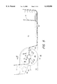
- FIG. 5 is a sectional view taken along line V--V of FIG. 1;
- FIG. 6 is a sectional view of the container taken along line VI--VI of FIG. 5, with the wheel assembly shown in front elevation, a portion thereof being broken away.
- an illustrative open top container includes a hollow body 10, preferably of a molded plastics material.
- the side wall 11 of and the bottom wall 16 of body 10 define a chamber 12 for receiving through its open top 14 selected materials (not shown), such as rubbish, refuse, and the like.
- the bottom end wall 16 is shaped so as to define a pocket 18 having an opening 20 on an outside (bottom) surface 22 of that wall 16, the pocket extending upwardly into the chamber 12.
- Pocket 18 comprises side walls 19A, 19B and a top wall 19C (FIG. 6).
- First and second C-configured clips 24, 26 are molded integrally with the body 10.
- Each of the clips 24, 26 includes first and second members 28, 30 that extend outwardly from the outside surface 22 of the end wall 16 and a circularly curved center section 31 that is a part of end wall 16 (FIGS. 4-6).
- the clip members 28, 30 define a gap or open portion 32 for each of the clips 24, 26.
- the open portions 32 of the clips 24, 26 face outwardly (downwardly as shown in FIGS. 5 and 6) from the bottom end wall 16, away from the chamber 12.
- the first clip 24 is disposed on a first side of the pocket 18 and is open to that pocket (FIG. 6).
- the second clip 26 is disposed on a second side of the pocket 18 and is open to that pocket.
- a wheel assembly 34 includes a wheel 36 and an axle 38 having first and second mutually aligned cylindrical portions 40 and 44 extending from first and second sides 42, 46 separately of the wheel.
- the first axle portion 40 is received by the first spring clip 24 in snap-in fashion, and the axle second portion 44 similarly is received by the second spring clip 26 in snap-in fashion, so as to securely but releasably mount the wheel assembly 34 on the end wall 16.
- the wheel 36 extends into the pocket 18 with a portion of the wheel extending out of the pocket. Preferably, but not necessarily, wheel 36 projects beyond a lower-most plane 50 (FIG. 5) of bottom end wall 16.
- spring clip 24 While the spring clip 24 is open towards the pocket 18 (FIG. 6), it is in part closed on its opposite side by a stop member 52 which is integral with the end wall 16 and clip members 28, 30 and 31 and partially closes off one side of the clip 24 to prevent axial movement of the axle 38 therebeyond.
- spring clip 26 is open towards the pocket 18, it is closed in part on its opposite side by a stop member in the form of a rib 54 formed integral with and extending radially from curved member 31 of clip 26.
- the rib 54 coacts with the adjacent end of axle 38 so as to limit axial movement of the axle away from stop member 52.
- the axle 38 is snugly retained by the clips 24, 26 between the stop members 52, 54.
- the container is provided with two wheel assemblies 34, 56.
- the end wall 16 defines a second like pocket 58 open on the outside surface 22 of the end wall 16 and extending into the chamber 12.
- Third and fourth C-configured clips 64, 66 are molded integrally with body 10 at opposite sides of second pocket 58.
- Each of the clips 64, 66 includes first and second members 68, 70 (FIG. 4) that extend outwardly from the outside surface 22 of the end wall 16, and a circularly curved center section 71 (FIG. 3) that is a part of end wall 16.
- the clip members 68, 70 define a gap or open portion 72 for each of the clips 64, 66.
- the open portions 72 of the clips 64, 66 face outwardly from the bottom end wall 16, similarly to clips 24, 26, away from the chamber 12.
- the third clip 64 is disposed on a first side of the pocket 58 and is open to that pocket.
- the fourth clip 66 is disposed on a second side of the pocket 58 and is open to that pocket.
- the wheel assembly 56 includes a wheel 76 and an axle 78 having a first cylindrical portion 80 extending from a first side 82 of the wheel 76, and a second cylindrical portion 84 extending from a second side 86 of the wheel 76.
- the first axle portion 80 is received by the third spring clip 64 in snap-in fashion
- the second axle portion 84 similarly is received by the fourth spring clip 66 in snap-in fashion, so as to securely but releasably mount the wheel assembly 56 on the end wall 16.
- the wheel 76 extends into the pocket 58 with a portion of the wheel extending out of the pocket and beyond a lower-most plane 50 of the end wall 16, similar to first wheel portion 48 (FIG. 5).
- spring clip 64 While the spring clip 64 is open towards the pocket 58, it is in part closed on its opposite side by a stop member (not shown) similar to stop member 52, and which is integral with the end wall 16 and which closes off one side of the clip 64 to prevent axial movement of the axle 78 therebeyond.
- spring clip 66 is open towards the pocket 58, it is closed in part on its opposite side by a stop member in the form of a rib (not shown) similar to rib 54 (FIG. 6) extending from end wall outside surface 22.
- Those stop members coact with the adjacent ends of axle 78 so as to limit its axial movement while it is gripped by clips 64, 66.
- the body 10 is molded of a plastic material, including the clip members 28, 30 and 68, 70.
- the wheel assemblies also are made of plastic. It is a preferred and novel feature of the invention to mold the axles and wheels as a one-piece unit. More specifically, in applicant's preferred embodiment, the axle portions 40, 44 and 80, 84 are formed as integral coaxial extension of the center or hub portions of wheels 36, 76. Preferably such wheel assemblies are made of high density polyethylene. These unitary assemblies 34, 56 are easily snapped into the clips without use of any tools and without requiring any further wheel mounting procedure. The diameters of axle portions 40, 44 and 80, 84 are sized so that they can rotate on their axes while captured by clips 24, 26 and 64, 66 respectively.
- the bottom end wall 16 may be formed so that its outer surface defines a channel 90 for receiving the portion of the common axle member (not shown) that extends between the two wheels.
- Channel 90 is formed with a circularly-curved cross-sectional configuration.
- Channel 90 extends between clips 26 and 66 and forms an extension of the circularly curved center sections 31, 71 of those clips.
- the mold for making the plastic container is modified so as to prevent formation of rib 54 and its counterpart for clip 64.
- the rib 54 may be formed as shown but the common shaft contoured so as to override these ribs, whereupon the ribs serve as bearings for the further axle portion.
- the container 10 also is formed with a top handle 92 (FIGS. 2-4) and a bottom hand-grip provided by forming a recess 94 in the bottom wall 16.
- Recess 94 is centered between the two wheel pockets 18 and 58 and is located near the perimeter of the bottom wall, so as to leave a narrow hand-gripping section 96 aligned with handle 92.
- the container is grasped by handle 92 and tilted so that the only contact between the container and a surface on which the container rests is through the wheel or wheels mounted thereon.
- the container is then rolled to an appropriate dump site as, for example, a refuse collection truck.
- the axles 38, 78 turn in their respective clips 24, 26 and 64, 66.
- wheeled container having thereon one or more wheel assemblies, which wheel assemblies may be pre-assembled and quickly and easily snap-fitted onto the container.
- the present invention is by no means limited to the particular construction herein disclosed and/or shown in the drawings, but also comprises modifications or equivalents within the scope of the claims.
- the container is shown as having a generally cylindrical or barrel shape, it is to be understood that it may have some other cross-sectional configurations, e.g., its side wall 11 may define a chamber 12 of rectangular cross-section.
- a two-wheeled container is shown for illustrative purposes, it will be apparent that similar devices such as wheel-barrows, carts, mobile collection boxes, and the like, typically may be fitted with 14 wheels as described herein.
Abstract
Description
Claims (1)
Priority Applications (2)
| Application Number | Priority Date | Filing Date | Title |
|---|---|---|---|
| US09/137,732 US6145856A (en) | 1998-08-21 | 1998-08-21 | Wheeled container |
| CA002273901A CA2273901A1 (en) | 1998-08-21 | 1999-06-08 | A wheeled container |
Applications Claiming Priority (1)
| Application Number | Priority Date | Filing Date | Title |
|---|---|---|---|
| US09/137,732 US6145856A (en) | 1998-08-21 | 1998-08-21 | Wheeled container |
Publications (1)
| Publication Number | Publication Date |
|---|---|
| US6145856A true US6145856A (en) | 2000-11-14 |
Family
ID=22478827
Family Applications (1)
| Application Number | Title | Priority Date | Filing Date |
|---|---|---|---|
| US09/137,732 Expired - Fee Related US6145856A (en) | 1998-08-21 | 1998-08-21 | Wheeled container |
Country Status (2)
| Country | Link |
|---|---|
| US (1) | US6145856A (en) |
| CA (1) | CA2273901A1 (en) |
Cited By (31)
| Publication number | Priority date | Publication date | Assignee | Title |
|---|---|---|---|---|
| US6203034B1 (en) * | 1999-01-14 | 2001-03-20 | Contico International, Llc | Transportable container |
| US6328320B1 (en) * | 1999-04-21 | 2001-12-11 | Cascade Engineering, Inc. | Waste container and axle assembly therefor |
| US6460867B2 (en) * | 2000-02-07 | 2002-10-08 | Otto Sciulli | Golf cart |
| US6471221B1 (en) * | 2001-02-21 | 2002-10-29 | Mcgarry Kevin | Trash can system |
| US6550793B2 (en) * | 2001-03-16 | 2003-04-22 | Wallace T. Carter | One-piece molded/copolymeric wheeled display case |
| WO2003066175A1 (en) * | 2002-02-04 | 2003-08-14 | Lifetime Products, Inc. | Portable basketball system |
| US20030178800A1 (en) * | 2002-03-21 | 2003-09-25 | Fite David Lee | Hamper assembly with laundry supply storage containers |
| GB2390821A (en) * | 2002-02-04 | 2004-01-21 | Lifetime Prod Inc | Portable basketball system |
| US20040108666A1 (en) * | 2002-08-02 | 2004-06-10 | Rubbermaid Commercial Products Llc | Nestable container |
| US6749206B1 (en) * | 1998-05-22 | 2004-06-15 | Floyd S. Butterfield | Container for recyclable materials |
| US6769702B2 (en) | 2001-04-02 | 2004-08-03 | Young Manufacturing Co., Llc | Reinforced and wheeled refuse container |
| US20050212237A1 (en) * | 2004-03-23 | 2005-09-29 | Paul Lin | Wheelbarrow having an auxiliary rear wheel assembly |
| US20060175779A1 (en) * | 2005-02-10 | 2006-08-10 | Zvi Zak | Wheeled bucket |
| US20070045974A1 (en) * | 2005-08-24 | 2007-03-01 | Young Roger L | Wheeled can for bar refuse |
| US7192037B1 (en) * | 2004-04-26 | 2007-03-20 | Pena Christopher | Lid assembly and method of use |
| US20070191151A1 (en) * | 2006-01-20 | 2007-08-16 | Nye S C | Basketball system |
| US20080039242A1 (en) * | 2006-08-08 | 2008-02-14 | Nye S Curtis | Basketball system |
| US20110042391A1 (en) * | 2008-12-11 | 2011-02-24 | M & C Innovations, Llc | Collapsible coolers |
| US7959030B2 (en) * | 2005-04-29 | 2011-06-14 | Bercom International, Llc | Roller brush adaptable hand-held container having sidewall ramp portion |
| US20110214400A1 (en) * | 2009-10-09 | 2011-09-08 | Rubbermaid, Incorporated | Multi-position hinge |
| US8430265B2 (en) | 2008-12-11 | 2013-04-30 | M & C Innovations, Llc | Collapsible coolers |
| US20130119625A1 (en) * | 2011-11-15 | 2013-05-16 | Rehrig Pacific Company | Wheeled container with repositionable axle |
| US20130214501A1 (en) * | 2008-12-11 | 2013-08-22 | M & C Innovations, Llc | Cooler having removable wheel assembly |
| USD699400S1 (en) * | 2013-03-24 | 2014-02-11 | Keter Plastic Ltd. | Animal feeder |
| US8695839B1 (en) | 2011-06-17 | 2014-04-15 | M & C Innovations, Llc | Cooler with wrap-around side cover |
| USD716002S1 (en) * | 2013-06-14 | 2014-10-21 | Niall Greenan | Container |
| US8875964B1 (en) | 2011-06-16 | 2014-11-04 | M & C Innovations, Llc | Backpack collapsible coolers |
| US8992350B2 (en) | 2011-06-29 | 2015-03-31 | Lifetime Products, Inc. | Triggerless handle mechanism and shock absorbing elements for basketball system |
| US9022395B1 (en) * | 2011-06-17 | 2015-05-05 | M & C Innovations, Llc | Cooler having removable wheel assembly |
| USD802925S1 (en) | 2016-04-29 | 2017-11-21 | Sterilite Corporation | Basket |
| US10766695B2 (en) | 2016-12-15 | 2020-09-08 | Rander Products, Llc | Assembly and method of use for a portable work surface |
Families Citing this family (4)
| Publication number | Priority date | Publication date | Assignee | Title |
|---|---|---|---|---|
| US7445297B2 (en) | 2006-01-19 | 2008-11-04 | Ipl Inc. | Wheel assembly for mounting to an axle of a wheeled product |
| US9371181B2 (en) | 2007-04-05 | 2016-06-21 | Jake, Connor & Crew, Inc. | Secure accumulation/disposal bin |
| USD594169S1 (en) | 2007-04-05 | 2009-06-09 | Jake's Holding Corporation | Accumulation bin |
| CA2810213C (en) | 2012-05-25 | 2019-05-28 | Ipl Inc. | Wheel built-in locking system and method |
Citations (18)
| Publication number | Priority date | Publication date | Assignee | Title |
|---|---|---|---|---|
| US1014475A (en) * | 1911-02-20 | 1912-01-09 | Richardson Scale Company | Refuse-receptacle. |
| US3306623A (en) * | 1964-11-12 | 1967-02-28 | Dorothea M Weitzner | Roller skates for shoes |
| US3346271A (en) * | 1965-07-06 | 1967-10-10 | Fred E Parsons | Nestable cart of molded material |
| US3366397A (en) * | 1966-05-09 | 1968-01-30 | Charles F. Zeilstra | Rubbish carrying hand cart |
| US4351539A (en) * | 1980-07-30 | 1982-09-28 | Ams Industries, Inc. | Trash barrel |
| US4550813A (en) * | 1984-03-28 | 1985-11-05 | Browning Arthur J | Molded wheeled luggage, ensemble thereof and process for making the same |
| US4674759A (en) * | 1985-05-21 | 1987-06-23 | Parker Bruce H | Trash container wheel structure |
| US4848782A (en) * | 1987-01-29 | 1989-07-18 | Peter Schmidt | Transport device for athletic equipment |
| US5031796A (en) * | 1989-03-08 | 1991-07-16 | Fritz Schafer Gesellschaft Mit Beschrankter Haftung | Ventilating system for garbage containers |
| US5088750A (en) * | 1990-04-30 | 1992-02-18 | Otto Industries, Inc. | Multi-functional waste container |
| US5205433A (en) * | 1991-03-06 | 1993-04-27 | Bartholomaeus Bitsch | Waste-collecting container |
| US5217135A (en) * | 1990-04-09 | 1993-06-08 | The Heil Co. | Refuse container with snap-on cover |
| US5235795A (en) * | 1990-05-09 | 1993-08-17 | Deroyal Industries, Inc. | System for the delivery, storage and disposal of medical supplies |
| US5244218A (en) * | 1991-07-22 | 1993-09-14 | Irwin Sr John C | Waste container having oriented compartments |
| US5683097A (en) * | 1995-06-06 | 1997-11-04 | Rubbermaid Specialty Products Inc. | Insulated container |
| US5692761A (en) * | 1996-07-15 | 1997-12-02 | Republic Tool & Mfg. Corp. | Utility cart |
| US5722788A (en) * | 1996-01-24 | 1998-03-03 | Bent Manfacturing Company | Traffic delineator with wheels |
| US5743542A (en) * | 1996-01-31 | 1998-04-28 | Rubbermaid Incorporated | Refuse container having retractable wheel assembly |
-
1998
- 1998-08-21 US US09/137,732 patent/US6145856A/en not_active Expired - Fee Related
-
1999
- 1999-06-08 CA CA002273901A patent/CA2273901A1/en not_active Abandoned
Patent Citations (18)
| Publication number | Priority date | Publication date | Assignee | Title |
|---|---|---|---|---|
| US1014475A (en) * | 1911-02-20 | 1912-01-09 | Richardson Scale Company | Refuse-receptacle. |
| US3306623A (en) * | 1964-11-12 | 1967-02-28 | Dorothea M Weitzner | Roller skates for shoes |
| US3346271A (en) * | 1965-07-06 | 1967-10-10 | Fred E Parsons | Nestable cart of molded material |
| US3366397A (en) * | 1966-05-09 | 1968-01-30 | Charles F. Zeilstra | Rubbish carrying hand cart |
| US4351539A (en) * | 1980-07-30 | 1982-09-28 | Ams Industries, Inc. | Trash barrel |
| US4550813A (en) * | 1984-03-28 | 1985-11-05 | Browning Arthur J | Molded wheeled luggage, ensemble thereof and process for making the same |
| US4674759A (en) * | 1985-05-21 | 1987-06-23 | Parker Bruce H | Trash container wheel structure |
| US4848782A (en) * | 1987-01-29 | 1989-07-18 | Peter Schmidt | Transport device for athletic equipment |
| US5031796A (en) * | 1989-03-08 | 1991-07-16 | Fritz Schafer Gesellschaft Mit Beschrankter Haftung | Ventilating system for garbage containers |
| US5217135A (en) * | 1990-04-09 | 1993-06-08 | The Heil Co. | Refuse container with snap-on cover |
| US5088750A (en) * | 1990-04-30 | 1992-02-18 | Otto Industries, Inc. | Multi-functional waste container |
| US5235795A (en) * | 1990-05-09 | 1993-08-17 | Deroyal Industries, Inc. | System for the delivery, storage and disposal of medical supplies |
| US5205433A (en) * | 1991-03-06 | 1993-04-27 | Bartholomaeus Bitsch | Waste-collecting container |
| US5244218A (en) * | 1991-07-22 | 1993-09-14 | Irwin Sr John C | Waste container having oriented compartments |
| US5683097A (en) * | 1995-06-06 | 1997-11-04 | Rubbermaid Specialty Products Inc. | Insulated container |
| US5722788A (en) * | 1996-01-24 | 1998-03-03 | Bent Manfacturing Company | Traffic delineator with wheels |
| US5743542A (en) * | 1996-01-31 | 1998-04-28 | Rubbermaid Incorporated | Refuse container having retractable wheel assembly |
| US5692761A (en) * | 1996-07-15 | 1997-12-02 | Republic Tool & Mfg. Corp. | Utility cart |
Cited By (42)
| Publication number | Priority date | Publication date | Assignee | Title |
|---|---|---|---|---|
| US6749206B1 (en) * | 1998-05-22 | 2004-06-15 | Floyd S. Butterfield | Container for recyclable materials |
| US6203034B1 (en) * | 1999-01-14 | 2001-03-20 | Contico International, Llc | Transportable container |
| US6328320B1 (en) * | 1999-04-21 | 2001-12-11 | Cascade Engineering, Inc. | Waste container and axle assembly therefor |
| US6460867B2 (en) * | 2000-02-07 | 2002-10-08 | Otto Sciulli | Golf cart |
| US6471221B1 (en) * | 2001-02-21 | 2002-10-29 | Mcgarry Kevin | Trash can system |
| US6550793B2 (en) * | 2001-03-16 | 2003-04-22 | Wallace T. Carter | One-piece molded/copolymeric wheeled display case |
| US6761368B2 (en) | 2001-03-16 | 2004-07-13 | Wallace T. Carter | Wheeled container |
| US6769702B2 (en) | 2001-04-02 | 2004-08-03 | Young Manufacturing Co., Llc | Reinforced and wheeled refuse container |
| WO2003066175A1 (en) * | 2002-02-04 | 2003-08-14 | Lifetime Products, Inc. | Portable basketball system |
| GB2390821B (en) * | 2002-02-04 | 2005-10-26 | Lifetime Prod Inc | Portable basketball system |
| GB2390821A (en) * | 2002-02-04 | 2004-01-21 | Lifetime Prod Inc | Portable basketball system |
| US20030162611A1 (en) * | 2002-02-04 | 2003-08-28 | Brent Steed | Portable basketball system |
| US6866596B2 (en) | 2002-02-04 | 2005-03-15 | Lifetime Products, Inc. | Portable basketball system |
| US20030178800A1 (en) * | 2002-03-21 | 2003-09-25 | Fite David Lee | Hamper assembly with laundry supply storage containers |
| US6761367B2 (en) * | 2002-03-21 | 2004-07-13 | David Lee Fite | Hamper assembly with laundry supply storage containers |
| US20040108666A1 (en) * | 2002-08-02 | 2004-06-10 | Rubbermaid Commercial Products Llc | Nestable container |
| US20050212237A1 (en) * | 2004-03-23 | 2005-09-29 | Paul Lin | Wheelbarrow having an auxiliary rear wheel assembly |
| US7192037B1 (en) * | 2004-04-26 | 2007-03-20 | Pena Christopher | Lid assembly and method of use |
| US20060175779A1 (en) * | 2005-02-10 | 2006-08-10 | Zvi Zak | Wheeled bucket |
| US8297628B2 (en) | 2005-02-10 | 2012-10-30 | Keter Plastic Ltd. | Wheeled bucket |
| US7959030B2 (en) * | 2005-04-29 | 2011-06-14 | Bercom International, Llc | Roller brush adaptable hand-held container having sidewall ramp portion |
| US20070045974A1 (en) * | 2005-08-24 | 2007-03-01 | Young Roger L | Wheeled can for bar refuse |
| US20070191151A1 (en) * | 2006-01-20 | 2007-08-16 | Nye S C | Basketball system |
| US8708844B2 (en) | 2006-01-20 | 2014-04-29 | Lifetime Products, Inc. | Basketball system |
| US20080039242A1 (en) * | 2006-08-08 | 2008-02-14 | Nye S Curtis | Basketball system |
| US20110042391A1 (en) * | 2008-12-11 | 2011-02-24 | M & C Innovations, Llc | Collapsible coolers |
| US8430265B2 (en) | 2008-12-11 | 2013-04-30 | M & C Innovations, Llc | Collapsible coolers |
| US9211901B2 (en) * | 2008-12-11 | 2015-12-15 | M & C Innovations, Llc | Cooler having removable wheel assembly |
| US20130214501A1 (en) * | 2008-12-11 | 2013-08-22 | M & C Innovations, Llc | Cooler having removable wheel assembly |
| US20110214400A1 (en) * | 2009-10-09 | 2011-09-08 | Rubbermaid, Incorporated | Multi-position hinge |
| US9102427B2 (en) * | 2009-10-09 | 2015-08-11 | Rubbermaid Incorporated | Multi-position hinge |
| US8875964B1 (en) | 2011-06-16 | 2014-11-04 | M & C Innovations, Llc | Backpack collapsible coolers |
| US8695839B1 (en) | 2011-06-17 | 2014-04-15 | M & C Innovations, Llc | Cooler with wrap-around side cover |
| US9022395B1 (en) * | 2011-06-17 | 2015-05-05 | M & C Innovations, Llc | Cooler having removable wheel assembly |
| US8992350B2 (en) | 2011-06-29 | 2015-03-31 | Lifetime Products, Inc. | Triggerless handle mechanism and shock absorbing elements for basketball system |
| US9675859B2 (en) | 2011-06-29 | 2017-06-13 | Lifetime Products, Inc. | Triggerless handle mechanism and shock absorbing elements for basketball system |
| US8919791B2 (en) * | 2011-11-15 | 2014-12-30 | Rehrig Pacific Company | Wheeled container with repositionable axle |
| US20130119625A1 (en) * | 2011-11-15 | 2013-05-16 | Rehrig Pacific Company | Wheeled container with repositionable axle |
| USD699400S1 (en) * | 2013-03-24 | 2014-02-11 | Keter Plastic Ltd. | Animal feeder |
| USD716002S1 (en) * | 2013-06-14 | 2014-10-21 | Niall Greenan | Container |
| USD802925S1 (en) | 2016-04-29 | 2017-11-21 | Sterilite Corporation | Basket |
| US10766695B2 (en) | 2016-12-15 | 2020-09-08 | Rander Products, Llc | Assembly and method of use for a portable work surface |
Also Published As
| Publication number | Publication date |
|---|---|
| CA2273901A1 (en) | 2000-02-21 |
Similar Documents
| Publication | Publication Date | Title |
|---|---|---|
| US6145856A (en) | Wheeled container | |
| US5547104A (en) | Waste container with dump handle | |
| US6053354A (en) | Container with hinged lid assembly | |
| US9550395B2 (en) | Wheel assembly | |
| EP3821186A1 (en) | Container with axle-less wheel assembly | |
| US6637835B2 (en) | Plastic wheel assembly and mounting sleeve with stabilizing recess | |
| CA2469317C (en) | Trash cart | |
| US6170920B1 (en) | Blow molded wheel with axel retainer | |
| US4674759A (en) | Trash container wheel structure | |
| US4401312A (en) | Automated trash collection receptacle | |
| US6280001B1 (en) | Waste container and wheel assembly with pultruded axle | |
| US5465844A (en) | Wheeled nestable refuse container | |
| FR2744108A1 (en) | STORAGE CONTAINER ON WHEELS, SUCH AS A BIN | |
| US20070045974A1 (en) | Wheeled can for bar refuse | |
| US6769702B2 (en) | Reinforced and wheeled refuse container | |
| US10046784B2 (en) | Trailer hitch attachable insulated coolers and methods of making and using the same | |
| US5749121A (en) | Wheel and housing for table leg | |
| US7464829B1 (en) | Divider assembly for waste container | |
| EP0209455B1 (en) | Dolly which can be solidarily attached to a container to facilitate its displacement | |
| CN211642480U (en) | Handlebar sleeve and handlebar for vehicle and vehicle | |
| CA2472600C (en) | Plastic wheel assembly and mounting sleeve with stabilizing recess | |
| USD410615S (en) | Spoke design for an automotive vehicle wheel | |
| WO2001002252A1 (en) | Sack holder and system for its support | |
| WO2003059653A2 (en) | Plastic wheel assembly and mounting sleeve with stabilizing recess | |
| GB2033218A (en) | Improvements in or Relating to Castors |
Legal Events
| Date | Code | Title | Description |
|---|---|---|---|
| AS | Assignment |
Owner name: HOLIDAY HOUSEWARES, INC., MASSACHUSETTS Free format text: ASSIGNMENT OF ASSIGNORS INTEREST;ASSIGNOR:CONTI, RINO;REEL/FRAME:009413/0461 Effective date: 19980818 |
|
| FEPP | Fee payment procedure |
Free format text: PAYOR NUMBER ASSIGNED (ORIGINAL EVENT CODE: ASPN); ENTITY STATUS OF PATENT OWNER: SMALL ENTITY |
|
| FPAY | Fee payment |
Year of fee payment: 4 |
|
| AS | Assignment |
Owner name: CAPITALSOURCE FINANCE LLC, MARYLAND Free format text: ASSIGNMENT;ASSIGNOR:AERO HOUSEWARES, L.L.C.;REEL/FRAME:018645/0392 Effective date: 20061117 |
|
| AS | Assignment |
Owner name: THE CIT GROUP/COMMERCIAL SERVICES, INC., NEW YORK Free format text: SECURITY AGREEMENT;ASSIGNOR:AERO HOUSEWARES, L.L.C.;REEL/FRAME:019094/0327 Effective date: 20070326 |
|
| AS | Assignment |
Owner name: AERO HOUSEWARES, L.L.C., MASSACHUSETTS Free format text: TERMINATION OF SECURITY AGREEMENT;ASSIGNOR:CAPITALSOURCE FINANCE LLC;REEL/FRAME:019134/0992 Effective date: 20061231 |
|
| REMI | Maintenance fee reminder mailed | ||
| AS | Assignment |
Owner name: HOLIDAY HOUSEWARES, INC., MASSACHUSETTS Free format text: SECURITY AGREEMENT;ASSIGNOR:AERO HOUSEWARES, LLC.;REEL/FRAME:021050/0448 Effective date: 20061114 Owner name: PLASTICAN, INC., MASSACHUSETTS Free format text: SECURITY AGREEMENT;ASSIGNOR:HOLIDAY HOUSEWARES, INC.;REEL/FRAME:021050/0481 Effective date: 20071228 |
|
| LAPS | Lapse for failure to pay maintenance fees | ||
| STCH | Information on status: patent discontinuation |
Free format text: PATENT EXPIRED DUE TO NONPAYMENT OF MAINTENANCE FEES UNDER 37 CFR 1.362 |
|
| FP | Lapsed due to failure to pay maintenance fee |
Effective date: 20081114 |
|
| AS | Assignment |
Owner name: HOLIDAY HOUSEWARES, INC., MASSACHUSETTS Free format text: RELEASE BY SECURED PARTY;ASSIGNOR:PLASTICAN, INC.;REEL/FRAME:025026/0495 Effective date: 20100922 |