US6146576A - Method of forming advanced cured resin composite parts - Google Patents
Method of forming advanced cured resin composite parts Download PDFInfo
- Publication number
- US6146576A US6146576A US08/852,039 US85203997A US6146576A US 6146576 A US6146576 A US 6146576A US 85203997 A US85203997 A US 85203997A US 6146576 A US6146576 A US 6146576A
- Authority
- US
- United States
- Prior art keywords
- composite material
- mold
- conductive fibers
- layer
- resin
- Prior art date
- Legal status (The legal status is an assumption and is not a legal conclusion. Google has not performed a legal analysis and makes no representation as to the accuracy of the status listed.)
- Expired - Fee Related
Links
Images


Classifications
-
- B—PERFORMING OPERATIONS; TRANSPORTING
- B29—WORKING OF PLASTICS; WORKING OF SUBSTANCES IN A PLASTIC STATE IN GENERAL
- B29C—SHAPING OR JOINING OF PLASTICS; SHAPING OF MATERIAL IN A PLASTIC STATE, NOT OTHERWISE PROVIDED FOR; AFTER-TREATMENT OF THE SHAPED PRODUCTS, e.g. REPAIRING
- B29C66/00—General aspects of processes or apparatus for joining preformed parts
- B29C66/01—General aspects dealing with the joint area or with the area to be joined
- B29C66/05—Particular design of joint configurations
- B29C66/10—Particular design of joint configurations particular design of the joint cross-sections
- B29C66/11—Joint cross-sections comprising a single joint-segment, i.e. one of the parts to be joined comprising a single joint-segment in the joint cross-section
- B29C66/112—Single lapped joints
- B29C66/1122—Single lap to lap joints, i.e. overlap joints
-
- B—PERFORMING OPERATIONS; TRANSPORTING
- B29—WORKING OF PLASTICS; WORKING OF SUBSTANCES IN A PLASTIC STATE IN GENERAL
- B29C—SHAPING OR JOINING OF PLASTICS; SHAPING OF MATERIAL IN A PLASTIC STATE, NOT OTHERWISE PROVIDED FOR; AFTER-TREATMENT OF THE SHAPED PRODUCTS, e.g. REPAIRING
- B29C33/00—Moulds or cores; Details thereof or accessories therefor
- B29C33/02—Moulds or cores; Details thereof or accessories therefor with incorporated heating or cooling means
- B29C33/06—Moulds or cores; Details thereof or accessories therefor with incorporated heating or cooling means using radiation, e.g. electro-magnetic waves, induction heating
-
- B—PERFORMING OPERATIONS; TRANSPORTING
- B29—WORKING OF PLASTICS; WORKING OF SUBSTANCES IN A PLASTIC STATE IN GENERAL
- B29C—SHAPING OR JOINING OF PLASTICS; SHAPING OF MATERIAL IN A PLASTIC STATE, NOT OTHERWISE PROVIDED FOR; AFTER-TREATMENT OF THE SHAPED PRODUCTS, e.g. REPAIRING
- B29C35/00—Heating, cooling or curing, e.g. crosslinking or vulcanising; Apparatus therefor
- B29C35/02—Heating or curing, e.g. crosslinking or vulcanizing during moulding, e.g. in a mould
- B29C35/0272—Heating or curing, e.g. crosslinking or vulcanizing during moulding, e.g. in a mould using lost heating elements, i.e. heating means incorporated and remaining in the formed article
-
- B—PERFORMING OPERATIONS; TRANSPORTING
- B29—WORKING OF PLASTICS; WORKING OF SUBSTANCES IN A PLASTIC STATE IN GENERAL
- B29C—SHAPING OR JOINING OF PLASTICS; SHAPING OF MATERIAL IN A PLASTIC STATE, NOT OTHERWISE PROVIDED FOR; AFTER-TREATMENT OF THE SHAPED PRODUCTS, e.g. REPAIRING
- B29C41/00—Shaping by coating a mould, core or other substrate, i.e. by depositing material and stripping-off the shaped article; Apparatus therefor
- B29C41/02—Shaping by coating a mould, core or other substrate, i.e. by depositing material and stripping-off the shaped article; Apparatus therefor for making articles of definite length, i.e. discrete articles
- B29C41/20—Shaping by coating a mould, core or other substrate, i.e. by depositing material and stripping-off the shaped article; Apparatus therefor for making articles of definite length, i.e. discrete articles incorporating preformed parts or layers, e.g. moulding inserts or for coating articles
-
- B—PERFORMING OPERATIONS; TRANSPORTING
- B29—WORKING OF PLASTICS; WORKING OF SUBSTANCES IN A PLASTIC STATE IN GENERAL
- B29C—SHAPING OR JOINING OF PLASTICS; SHAPING OF MATERIAL IN A PLASTIC STATE, NOT OTHERWISE PROVIDED FOR; AFTER-TREATMENT OF THE SHAPED PRODUCTS, e.g. REPAIRING
- B29C41/00—Shaping by coating a mould, core or other substrate, i.e. by depositing material and stripping-off the shaped article; Apparatus therefor
- B29C41/34—Component parts, details or accessories; Auxiliary operations
- B29C41/50—Shaping under special conditions, e.g. vacuum
-
- B—PERFORMING OPERATIONS; TRANSPORTING
- B29—WORKING OF PLASTICS; WORKING OF SUBSTANCES IN A PLASTIC STATE IN GENERAL
- B29C—SHAPING OR JOINING OF PLASTICS; SHAPING OF MATERIAL IN A PLASTIC STATE, NOT OTHERWISE PROVIDED FOR; AFTER-TREATMENT OF THE SHAPED PRODUCTS, e.g. REPAIRING
- B29C65/00—Joining or sealing of preformed parts, e.g. welding of plastics materials; Apparatus therefor
- B29C65/02—Joining or sealing of preformed parts, e.g. welding of plastics materials; Apparatus therefor by heating, with or without pressure
- B29C65/34—Joining or sealing of preformed parts, e.g. welding of plastics materials; Apparatus therefor by heating, with or without pressure using heated elements which remain in the joint, e.g. "verlorenes Schweisselement"
- B29C65/3404—Joining or sealing of preformed parts, e.g. welding of plastics materials; Apparatus therefor by heating, with or without pressure using heated elements which remain in the joint, e.g. "verlorenes Schweisselement" characterised by the type of heated elements which remain in the joint
- B29C65/3436—Joining or sealing of preformed parts, e.g. welding of plastics materials; Apparatus therefor by heating, with or without pressure using heated elements which remain in the joint, e.g. "verlorenes Schweisselement" characterised by the type of heated elements which remain in the joint comprising independent continuous fibre-reinforcements
-
- B—PERFORMING OPERATIONS; TRANSPORTING
- B29—WORKING OF PLASTICS; WORKING OF SUBSTANCES IN A PLASTIC STATE IN GENERAL
- B29C—SHAPING OR JOINING OF PLASTICS; SHAPING OF MATERIAL IN A PLASTIC STATE, NOT OTHERWISE PROVIDED FOR; AFTER-TREATMENT OF THE SHAPED PRODUCTS, e.g. REPAIRING
- B29C65/00—Joining or sealing of preformed parts, e.g. welding of plastics materials; Apparatus therefor
- B29C65/02—Joining or sealing of preformed parts, e.g. welding of plastics materials; Apparatus therefor by heating, with or without pressure
- B29C65/34—Joining or sealing of preformed parts, e.g. welding of plastics materials; Apparatus therefor by heating, with or without pressure using heated elements which remain in the joint, e.g. "verlorenes Schweisselement"
- B29C65/3404—Joining or sealing of preformed parts, e.g. welding of plastics materials; Apparatus therefor by heating, with or without pressure using heated elements which remain in the joint, e.g. "verlorenes Schweisselement" characterised by the type of heated elements which remain in the joint
- B29C65/344—Joining or sealing of preformed parts, e.g. welding of plastics materials; Apparatus therefor by heating, with or without pressure using heated elements which remain in the joint, e.g. "verlorenes Schweisselement" characterised by the type of heated elements which remain in the joint being a woven or non-woven fabric or being a mesh
-
- B—PERFORMING OPERATIONS; TRANSPORTING
- B29—WORKING OF PLASTICS; WORKING OF SUBSTANCES IN A PLASTIC STATE IN GENERAL
- B29C—SHAPING OR JOINING OF PLASTICS; SHAPING OF MATERIAL IN A PLASTIC STATE, NOT OTHERWISE PROVIDED FOR; AFTER-TREATMENT OF THE SHAPED PRODUCTS, e.g. REPAIRING
- B29C66/00—General aspects of processes or apparatus for joining preformed parts
- B29C66/40—General aspects of joining substantially flat articles, e.g. plates, sheets or web-like materials; Making flat seams in tubular or hollow articles; Joining single elements to substantially flat surfaces
- B29C66/41—Joining substantially flat articles ; Making flat seams in tubular or hollow articles
- B29C66/43—Joining a relatively small portion of the surface of said articles
- B29C66/432—Joining a relatively small portion of the surface of said articles for making tubular articles or closed loops, e.g. by joining several sheets ; for making hollow articles or hollow preforms
- B29C66/4322—Joining a relatively small portion of the surface of said articles for making tubular articles or closed loops, e.g. by joining several sheets ; for making hollow articles or hollow preforms by joining a single sheet to itself
-
- B—PERFORMING OPERATIONS; TRANSPORTING
- B29—WORKING OF PLASTICS; WORKING OF SUBSTANCES IN A PLASTIC STATE IN GENERAL
- B29C—SHAPING OR JOINING OF PLASTICS; SHAPING OF MATERIAL IN A PLASTIC STATE, NOT OTHERWISE PROVIDED FOR; AFTER-TREATMENT OF THE SHAPED PRODUCTS, e.g. REPAIRING
- B29C66/00—General aspects of processes or apparatus for joining preformed parts
- B29C66/40—General aspects of joining substantially flat articles, e.g. plates, sheets or web-like materials; Making flat seams in tubular or hollow articles; Joining single elements to substantially flat surfaces
- B29C66/41—Joining substantially flat articles ; Making flat seams in tubular or hollow articles
- B29C66/43—Joining a relatively small portion of the surface of said articles
- B29C66/432—Joining a relatively small portion of the surface of said articles for making tubular articles or closed loops, e.g. by joining several sheets ; for making hollow articles or hollow preforms
- B29C66/4329—Joining a relatively small portion of the surface of said articles for making tubular articles or closed loops, e.g. by joining several sheets ; for making hollow articles or hollow preforms the joint lines being transversal but non-orthogonal with respect to the axis of said tubular articles, i.e. being oblique
-
- B—PERFORMING OPERATIONS; TRANSPORTING
- B29—WORKING OF PLASTICS; WORKING OF SUBSTANCES IN A PLASTIC STATE IN GENERAL
- B29C—SHAPING OR JOINING OF PLASTICS; SHAPING OF MATERIAL IN A PLASTIC STATE, NOT OTHERWISE PROVIDED FOR; AFTER-TREATMENT OF THE SHAPED PRODUCTS, e.g. REPAIRING
- B29C66/00—General aspects of processes or apparatus for joining preformed parts
- B29C66/40—General aspects of joining substantially flat articles, e.g. plates, sheets or web-like materials; Making flat seams in tubular or hollow articles; Joining single elements to substantially flat surfaces
- B29C66/41—Joining substantially flat articles ; Making flat seams in tubular or hollow articles
- B29C66/45—Joining of substantially the whole surface of the articles
-
- B—PERFORMING OPERATIONS; TRANSPORTING
- B29—WORKING OF PLASTICS; WORKING OF SUBSTANCES IN A PLASTIC STATE IN GENERAL
- B29C—SHAPING OR JOINING OF PLASTICS; SHAPING OF MATERIAL IN A PLASTIC STATE, NOT OTHERWISE PROVIDED FOR; AFTER-TREATMENT OF THE SHAPED PRODUCTS, e.g. REPAIRING
- B29C66/00—General aspects of processes or apparatus for joining preformed parts
- B29C66/40—General aspects of joining substantially flat articles, e.g. plates, sheets or web-like materials; Making flat seams in tubular or hollow articles; Joining single elements to substantially flat surfaces
- B29C66/49—Internally supporting the, e.g. tubular, article during joining
- B29C66/494—Internally supporting the, e.g. tubular, article during joining using an inflatable core
-
- B—PERFORMING OPERATIONS; TRANSPORTING
- B29—WORKING OF PLASTICS; WORKING OF SUBSTANCES IN A PLASTIC STATE IN GENERAL
- B29C—SHAPING OR JOINING OF PLASTICS; SHAPING OF MATERIAL IN A PLASTIC STATE, NOT OTHERWISE PROVIDED FOR; AFTER-TREATMENT OF THE SHAPED PRODUCTS, e.g. REPAIRING
- B29C66/00—General aspects of processes or apparatus for joining preformed parts
- B29C66/40—General aspects of joining substantially flat articles, e.g. plates, sheets or web-like materials; Making flat seams in tubular or hollow articles; Joining single elements to substantially flat surfaces
- B29C66/49—Internally supporting the, e.g. tubular, article during joining
- B29C66/496—Internally supporting the, e.g. tubular, article during joining using a support which remains in the joined object
-
- B—PERFORMING OPERATIONS; TRANSPORTING
- B29—WORKING OF PLASTICS; WORKING OF SUBSTANCES IN A PLASTIC STATE IN GENERAL
- B29C—SHAPING OR JOINING OF PLASTICS; SHAPING OF MATERIAL IN A PLASTIC STATE, NOT OTHERWISE PROVIDED FOR; AFTER-TREATMENT OF THE SHAPED PRODUCTS, e.g. REPAIRING
- B29C66/00—General aspects of processes or apparatus for joining preformed parts
- B29C66/80—General aspects of machine operations or constructions and parts thereof
- B29C66/81—General aspects of the pressing elements, i.e. the elements applying pressure on the parts to be joined in the area to be joined, e.g. the welding jaws or clamps
- B29C66/812—General aspects of the pressing elements, i.e. the elements applying pressure on the parts to be joined in the area to be joined, e.g. the welding jaws or clamps characterised by the composition, by the structure, by the intensive physical properties or by the optical properties of the material constituting the pressing elements, e.g. constituting the welding jaws or clamps
- B29C66/8126—General aspects of the pressing elements, i.e. the elements applying pressure on the parts to be joined in the area to be joined, e.g. the welding jaws or clamps characterised by the composition, by the structure, by the intensive physical properties or by the optical properties of the material constituting the pressing elements, e.g. constituting the welding jaws or clamps characterised by the intensive physical properties or by the optical properties of the material constituting the pressing elements, e.g. constituting the welding jaws or clamps
- B29C66/81261—Thermal properties, e.g. thermal conductivity, thermal expansion coefficient
-
- B—PERFORMING OPERATIONS; TRANSPORTING
- B29—WORKING OF PLASTICS; WORKING OF SUBSTANCES IN A PLASTIC STATE IN GENERAL
- B29C—SHAPING OR JOINING OF PLASTICS; SHAPING OF MATERIAL IN A PLASTIC STATE, NOT OTHERWISE PROVIDED FOR; AFTER-TREATMENT OF THE SHAPED PRODUCTS, e.g. REPAIRING
- B29C66/00—General aspects of processes or apparatus for joining preformed parts
- B29C66/80—General aspects of machine operations or constructions and parts thereof
- B29C66/81—General aspects of the pressing elements, i.e. the elements applying pressure on the parts to be joined in the area to be joined, e.g. the welding jaws or clamps
- B29C66/814—General aspects of the pressing elements, i.e. the elements applying pressure on the parts to be joined in the area to be joined, e.g. the welding jaws or clamps characterised by the design of the pressing elements, e.g. of the welding jaws or clamps
- B29C66/8145—General aspects of the pressing elements, i.e. the elements applying pressure on the parts to be joined in the area to be joined, e.g. the welding jaws or clamps characterised by the design of the pressing elements, e.g. of the welding jaws or clamps characterised by the constructional aspects of the pressing elements, e.g. of the welding jaws or clamps
- B29C66/81455—General aspects of the pressing elements, i.e. the elements applying pressure on the parts to be joined in the area to be joined, e.g. the welding jaws or clamps characterised by the design of the pressing elements, e.g. of the welding jaws or clamps characterised by the constructional aspects of the pressing elements, e.g. of the welding jaws or clamps being a fluid inflatable bag or bladder, a diaphragm or a vacuum bag for applying isostatic pressure
-
- B—PERFORMING OPERATIONS; TRANSPORTING
- B29—WORKING OF PLASTICS; WORKING OF SUBSTANCES IN A PLASTIC STATE IN GENERAL
- B29C—SHAPING OR JOINING OF PLASTICS; SHAPING OF MATERIAL IN A PLASTIC STATE, NOT OTHERWISE PROVIDED FOR; AFTER-TREATMENT OF THE SHAPED PRODUCTS, e.g. REPAIRING
- B29C66/00—General aspects of processes or apparatus for joining preformed parts
- B29C66/80—General aspects of machine operations or constructions and parts thereof
- B29C66/81—General aspects of the pressing elements, i.e. the elements applying pressure on the parts to be joined in the area to be joined, e.g. the welding jaws or clamps
- B29C66/814—General aspects of the pressing elements, i.e. the elements applying pressure on the parts to be joined in the area to be joined, e.g. the welding jaws or clamps characterised by the design of the pressing elements, e.g. of the welding jaws or clamps
- B29C66/8145—General aspects of the pressing elements, i.e. the elements applying pressure on the parts to be joined in the area to be joined, e.g. the welding jaws or clamps characterised by the design of the pressing elements, e.g. of the welding jaws or clamps characterised by the constructional aspects of the pressing elements, e.g. of the welding jaws or clamps
- B29C66/81471—General aspects of the pressing elements, i.e. the elements applying pressure on the parts to be joined in the area to be joined, e.g. the welding jaws or clamps characterised by the design of the pressing elements, e.g. of the welding jaws or clamps characterised by the constructional aspects of the pressing elements, e.g. of the welding jaws or clamps being a wrap-around tape or band
-
- B—PERFORMING OPERATIONS; TRANSPORTING
- B29—WORKING OF PLASTICS; WORKING OF SUBSTANCES IN A PLASTIC STATE IN GENERAL
- B29C—SHAPING OR JOINING OF PLASTICS; SHAPING OF MATERIAL IN A PLASTIC STATE, NOT OTHERWISE PROVIDED FOR; AFTER-TREATMENT OF THE SHAPED PRODUCTS, e.g. REPAIRING
- B29C66/00—General aspects of processes or apparatus for joining preformed parts
- B29C66/90—Measuring or controlling the joining process
- B29C66/91—Measuring or controlling the joining process by measuring or controlling the temperature, the heat or the thermal flux
- B29C66/912—Measuring or controlling the joining process by measuring or controlling the temperature, the heat or the thermal flux by measuring the temperature, the heat or the thermal flux
- B29C66/9121—Measuring or controlling the joining process by measuring or controlling the temperature, the heat or the thermal flux by measuring the temperature, the heat or the thermal flux by measuring the temperature
- B29C66/91221—Measuring or controlling the joining process by measuring or controlling the temperature, the heat or the thermal flux by measuring the temperature, the heat or the thermal flux by measuring the temperature of the parts to be joined
-
- B—PERFORMING OPERATIONS; TRANSPORTING
- B29—WORKING OF PLASTICS; WORKING OF SUBSTANCES IN A PLASTIC STATE IN GENERAL
- B29C—SHAPING OR JOINING OF PLASTICS; SHAPING OF MATERIAL IN A PLASTIC STATE, NOT OTHERWISE PROVIDED FOR; AFTER-TREATMENT OF THE SHAPED PRODUCTS, e.g. REPAIRING
- B29C66/00—General aspects of processes or apparatus for joining preformed parts
- B29C66/90—Measuring or controlling the joining process
- B29C66/91—Measuring or controlling the joining process by measuring or controlling the temperature, the heat or the thermal flux
- B29C66/914—Measuring or controlling the joining process by measuring or controlling the temperature, the heat or the thermal flux by controlling or regulating the temperature, the heat or the thermal flux
- B29C66/9141—Measuring or controlling the joining process by measuring or controlling the temperature, the heat or the thermal flux by controlling or regulating the temperature, the heat or the thermal flux by controlling or regulating the temperature
- B29C66/91411—Measuring or controlling the joining process by measuring or controlling the temperature, the heat or the thermal flux by controlling or regulating the temperature, the heat or the thermal flux by controlling or regulating the temperature of the parts to be joined, e.g. the joining process taking the temperature of the parts to be joined into account
-
- B—PERFORMING OPERATIONS; TRANSPORTING
- B29—WORKING OF PLASTICS; WORKING OF SUBSTANCES IN A PLASTIC STATE IN GENERAL
- B29C—SHAPING OR JOINING OF PLASTICS; SHAPING OF MATERIAL IN A PLASTIC STATE, NOT OTHERWISE PROVIDED FOR; AFTER-TREATMENT OF THE SHAPED PRODUCTS, e.g. REPAIRING
- B29C66/00—General aspects of processes or apparatus for joining preformed parts
- B29C66/90—Measuring or controlling the joining process
- B29C66/91—Measuring or controlling the joining process by measuring or controlling the temperature, the heat or the thermal flux
- B29C66/914—Measuring or controlling the joining process by measuring or controlling the temperature, the heat or the thermal flux by controlling or regulating the temperature, the heat or the thermal flux
- B29C66/9161—Measuring or controlling the joining process by measuring or controlling the temperature, the heat or the thermal flux by controlling or regulating the temperature, the heat or the thermal flux by controlling or regulating the heat or the thermal flux, i.e. the heat flux
- B29C66/91651—Measuring or controlling the joining process by measuring or controlling the temperature, the heat or the thermal flux by controlling or regulating the temperature, the heat or the thermal flux by controlling or regulating the heat or the thermal flux, i.e. the heat flux by controlling or regulating the heat generated by Joule heating or induction heating
- B29C66/91655—Measuring or controlling the joining process by measuring or controlling the temperature, the heat or the thermal flux by controlling or regulating the temperature, the heat or the thermal flux by controlling or regulating the heat or the thermal flux, i.e. the heat flux by controlling or regulating the heat generated by Joule heating or induction heating by controlling or regulating the current intensity
-
- B—PERFORMING OPERATIONS; TRANSPORTING
- B29—WORKING OF PLASTICS; WORKING OF SUBSTANCES IN A PLASTIC STATE IN GENERAL
- B29C—SHAPING OR JOINING OF PLASTICS; SHAPING OF MATERIAL IN A PLASTIC STATE, NOT OTHERWISE PROVIDED FOR; AFTER-TREATMENT OF THE SHAPED PRODUCTS, e.g. REPAIRING
- B29C70/00—Shaping composites, i.e. plastics material comprising reinforcements, fillers or preformed parts, e.g. inserts
- B29C70/04—Shaping composites, i.e. plastics material comprising reinforcements, fillers or preformed parts, e.g. inserts comprising reinforcements only, e.g. self-reinforcing plastics
- B29C70/28—Shaping operations therefor
- B29C70/54—Component parts, details or accessories; Auxiliary operations, e.g. feeding or storage of prepregs or SMC after impregnation or during ageing
-
- B—PERFORMING OPERATIONS; TRANSPORTING
- B29—WORKING OF PLASTICS; WORKING OF SUBSTANCES IN A PLASTIC STATE IN GENERAL
- B29C—SHAPING OR JOINING OF PLASTICS; SHAPING OF MATERIAL IN A PLASTIC STATE, NOT OTHERWISE PROVIDED FOR; AFTER-TREATMENT OF THE SHAPED PRODUCTS, e.g. REPAIRING
- B29C70/00—Shaping composites, i.e. plastics material comprising reinforcements, fillers or preformed parts, e.g. inserts
- B29C70/68—Shaping composites, i.e. plastics material comprising reinforcements, fillers or preformed parts, e.g. inserts by incorporating or moulding on preformed parts, e.g. inserts or layers, e.g. foam blocks
- B29C70/86—Incorporated in coherent impregnated reinforcing layers, e.g. by winding
-
- B—PERFORMING OPERATIONS; TRANSPORTING
- B29—WORKING OF PLASTICS; WORKING OF SUBSTANCES IN A PLASTIC STATE IN GENERAL
- B29C—SHAPING OR JOINING OF PLASTICS; SHAPING OF MATERIAL IN A PLASTIC STATE, NOT OTHERWISE PROVIDED FOR; AFTER-TREATMENT OF THE SHAPED PRODUCTS, e.g. REPAIRING
- B29C70/00—Shaping composites, i.e. plastics material comprising reinforcements, fillers or preformed parts, e.g. inserts
- B29C70/88—Shaping composites, i.e. plastics material comprising reinforcements, fillers or preformed parts, e.g. inserts characterised primarily by possessing specific properties, e.g. electrically conductive or locally reinforced
- B29C70/882—Shaping composites, i.e. plastics material comprising reinforcements, fillers or preformed parts, e.g. inserts characterised primarily by possessing specific properties, e.g. electrically conductive or locally reinforced partly or totally electrically conductive, e.g. for EMI shielding
-
- E—FIXED CONSTRUCTIONS
- E04—BUILDING
- E04C—STRUCTURAL ELEMENTS; BUILDING MATERIALS
- E04C5/00—Reinforcing elements, e.g. for concrete; Auxiliary elements therefor
- E04C5/07—Reinforcing elements of material other than metal, e.g. of glass, of plastics, or not exclusively made of metal
-
- E—FIXED CONSTRUCTIONS
- E04—BUILDING
- E04G—SCAFFOLDING; FORMS; SHUTTERING; BUILDING IMPLEMENTS OR AIDS, OR THEIR USE; HANDLING BUILDING MATERIALS ON THE SITE; REPAIRING, BREAKING-UP OR OTHER WORK ON EXISTING BUILDINGS
- E04G23/00—Working measures on existing buildings
- E04G23/02—Repairing, e.g. filling cracks; Restoring; Altering; Enlarging
- E04G23/0218—Increasing or restoring the load-bearing capacity of building construction elements
- E04G23/0225—Increasing or restoring the load-bearing capacity of building construction elements of circular building elements, e.g. by circular bracing
-
- E—FIXED CONSTRUCTIONS
- E04—BUILDING
- E04H—BUILDINGS OR LIKE STRUCTURES FOR PARTICULAR PURPOSES; SWIMMING OR SPLASH BATHS OR POOLS; MASTS; FENCING; TENTS OR CANOPIES, IN GENERAL
- E04H12/00—Towers; Masts or poles; Chimney stacks; Water-towers; Methods of erecting such structures
- E04H12/22—Sockets or holders for poles or posts
- E04H12/2292—Holders used for protection, repair or reinforcement of the post or pole
-
- B—PERFORMING OPERATIONS; TRANSPORTING
- B29—WORKING OF PLASTICS; WORKING OF SUBSTANCES IN A PLASTIC STATE IN GENERAL
- B29C—SHAPING OR JOINING OF PLASTICS; SHAPING OF MATERIAL IN A PLASTIC STATE, NOT OTHERWISE PROVIDED FOR; AFTER-TREATMENT OF THE SHAPED PRODUCTS, e.g. REPAIRING
- B29C35/00—Heating, cooling or curing, e.g. crosslinking or vulcanising; Apparatus therefor
- B29C35/02—Heating or curing, e.g. crosslinking or vulcanizing during moulding, e.g. in a mould
- B29C2035/0211—Heating or curing, e.g. crosslinking or vulcanizing during moulding, e.g. in a mould resistance heating
-
- B—PERFORMING OPERATIONS; TRANSPORTING
- B29—WORKING OF PLASTICS; WORKING OF SUBSTANCES IN A PLASTIC STATE IN GENERAL
- B29C—SHAPING OR JOINING OF PLASTICS; SHAPING OF MATERIAL IN A PLASTIC STATE, NOT OTHERWISE PROVIDED FOR; AFTER-TREATMENT OF THE SHAPED PRODUCTS, e.g. REPAIRING
- B29C37/00—Component parts, details, accessories or auxiliary operations, not covered by group B29C33/00 or B29C35/00
- B29C2037/90—Measuring, controlling or regulating
- B29C2037/903—Measuring, controlling or regulating by means of a computer
-
- B—PERFORMING OPERATIONS; TRANSPORTING
- B29—WORKING OF PLASTICS; WORKING OF SUBSTANCES IN A PLASTIC STATE IN GENERAL
- B29C—SHAPING OR JOINING OF PLASTICS; SHAPING OF MATERIAL IN A PLASTIC STATE, NOT OTHERWISE PROVIDED FOR; AFTER-TREATMENT OF THE SHAPED PRODUCTS, e.g. REPAIRING
- B29C33/00—Moulds or cores; Details thereof or accessories therefor
- B29C33/02—Moulds or cores; Details thereof or accessories therefor with incorporated heating or cooling means
-
- B—PERFORMING OPERATIONS; TRANSPORTING
- B29—WORKING OF PLASTICS; WORKING OF SUBSTANCES IN A PLASTIC STATE IN GENERAL
- B29C—SHAPING OR JOINING OF PLASTICS; SHAPING OF MATERIAL IN A PLASTIC STATE, NOT OTHERWISE PROVIDED FOR; AFTER-TREATMENT OF THE SHAPED PRODUCTS, e.g. REPAIRING
- B29C33/00—Moulds or cores; Details thereof or accessories therefor
- B29C33/38—Moulds or cores; Details thereof or accessories therefor characterised by the material or the manufacturing process
-
- B—PERFORMING OPERATIONS; TRANSPORTING
- B29—WORKING OF PLASTICS; WORKING OF SUBSTANCES IN A PLASTIC STATE IN GENERAL
- B29C—SHAPING OR JOINING OF PLASTICS; SHAPING OF MATERIAL IN A PLASTIC STATE, NOT OTHERWISE PROVIDED FOR; AFTER-TREATMENT OF THE SHAPED PRODUCTS, e.g. REPAIRING
- B29C33/00—Moulds or cores; Details thereof or accessories therefor
- B29C33/44—Moulds or cores; Details thereof or accessories therefor with means for, or specially constructed to facilitate, the removal of articles, e.g. of undercut articles
- B29C33/48—Moulds or cores; Details thereof or accessories therefor with means for, or specially constructed to facilitate, the removal of articles, e.g. of undercut articles with means for collapsing or disassembling
-
- B—PERFORMING OPERATIONS; TRANSPORTING
- B29—WORKING OF PLASTICS; WORKING OF SUBSTANCES IN A PLASTIC STATE IN GENERAL
- B29C—SHAPING OR JOINING OF PLASTICS; SHAPING OF MATERIAL IN A PLASTIC STATE, NOT OTHERWISE PROVIDED FOR; AFTER-TREATMENT OF THE SHAPED PRODUCTS, e.g. REPAIRING
- B29C65/00—Joining or sealing of preformed parts, e.g. welding of plastics materials; Apparatus therefor
- B29C65/02—Joining or sealing of preformed parts, e.g. welding of plastics materials; Apparatus therefor by heating, with or without pressure
- B29C65/34—Joining or sealing of preformed parts, e.g. welding of plastics materials; Apparatus therefor by heating, with or without pressure using heated elements which remain in the joint, e.g. "verlorenes Schweisselement"
- B29C65/3468—Joining or sealing of preformed parts, e.g. welding of plastics materials; Apparatus therefor by heating, with or without pressure using heated elements which remain in the joint, e.g. "verlorenes Schweisselement" characterised by the means for supplying heat to said heated elements which remain in the join, e.g. special electrical connectors of windings
-
- B—PERFORMING OPERATIONS; TRANSPORTING
- B29—WORKING OF PLASTICS; WORKING OF SUBSTANCES IN A PLASTIC STATE IN GENERAL
- B29C—SHAPING OR JOINING OF PLASTICS; SHAPING OF MATERIAL IN A PLASTIC STATE, NOT OTHERWISE PROVIDED FOR; AFTER-TREATMENT OF THE SHAPED PRODUCTS, e.g. REPAIRING
- B29C65/00—Joining or sealing of preformed parts, e.g. welding of plastics materials; Apparatus therefor
- B29C65/02—Joining or sealing of preformed parts, e.g. welding of plastics materials; Apparatus therefor by heating, with or without pressure
- B29C65/34—Joining or sealing of preformed parts, e.g. welding of plastics materials; Apparatus therefor by heating, with or without pressure using heated elements which remain in the joint, e.g. "verlorenes Schweisselement"
- B29C65/3472—Joining or sealing of preformed parts, e.g. welding of plastics materials; Apparatus therefor by heating, with or without pressure using heated elements which remain in the joint, e.g. "verlorenes Schweisselement" characterised by the composition of the heated elements which remain in the joint
- B29C65/3476—Joining or sealing of preformed parts, e.g. welding of plastics materials; Apparatus therefor by heating, with or without pressure using heated elements which remain in the joint, e.g. "verlorenes Schweisselement" characterised by the composition of the heated elements which remain in the joint being metallic
-
- B—PERFORMING OPERATIONS; TRANSPORTING
- B29—WORKING OF PLASTICS; WORKING OF SUBSTANCES IN A PLASTIC STATE IN GENERAL
- B29C—SHAPING OR JOINING OF PLASTICS; SHAPING OF MATERIAL IN A PLASTIC STATE, NOT OTHERWISE PROVIDED FOR; AFTER-TREATMENT OF THE SHAPED PRODUCTS, e.g. REPAIRING
- B29C65/00—Joining or sealing of preformed parts, e.g. welding of plastics materials; Apparatus therefor
- B29C65/02—Joining or sealing of preformed parts, e.g. welding of plastics materials; Apparatus therefor by heating, with or without pressure
- B29C65/34—Joining or sealing of preformed parts, e.g. welding of plastics materials; Apparatus therefor by heating, with or without pressure using heated elements which remain in the joint, e.g. "verlorenes Schweisselement"
- B29C65/3472—Joining or sealing of preformed parts, e.g. welding of plastics materials; Apparatus therefor by heating, with or without pressure using heated elements which remain in the joint, e.g. "verlorenes Schweisselement" characterised by the composition of the heated elements which remain in the joint
- B29C65/3484—Joining or sealing of preformed parts, e.g. welding of plastics materials; Apparatus therefor by heating, with or without pressure using heated elements which remain in the joint, e.g. "verlorenes Schweisselement" characterised by the composition of the heated elements which remain in the joint being non-metallic
- B29C65/3488—Joining or sealing of preformed parts, e.g. welding of plastics materials; Apparatus therefor by heating, with or without pressure using heated elements which remain in the joint, e.g. "verlorenes Schweisselement" characterised by the composition of the heated elements which remain in the joint being non-metallic being an electrically conductive polymer
-
- B—PERFORMING OPERATIONS; TRANSPORTING
- B29—WORKING OF PLASTICS; WORKING OF SUBSTANCES IN A PLASTIC STATE IN GENERAL
- B29C—SHAPING OR JOINING OF PLASTICS; SHAPING OF MATERIAL IN A PLASTIC STATE, NOT OTHERWISE PROVIDED FOR; AFTER-TREATMENT OF THE SHAPED PRODUCTS, e.g. REPAIRING
- B29C65/00—Joining or sealing of preformed parts, e.g. welding of plastics materials; Apparatus therefor
- B29C65/02—Joining or sealing of preformed parts, e.g. welding of plastics materials; Apparatus therefor by heating, with or without pressure
- B29C65/34—Joining or sealing of preformed parts, e.g. welding of plastics materials; Apparatus therefor by heating, with or without pressure using heated elements which remain in the joint, e.g. "verlorenes Schweisselement"
- B29C65/3472—Joining or sealing of preformed parts, e.g. welding of plastics materials; Apparatus therefor by heating, with or without pressure using heated elements which remain in the joint, e.g. "verlorenes Schweisselement" characterised by the composition of the heated elements which remain in the joint
- B29C65/3484—Joining or sealing of preformed parts, e.g. welding of plastics materials; Apparatus therefor by heating, with or without pressure using heated elements which remain in the joint, e.g. "verlorenes Schweisselement" characterised by the composition of the heated elements which remain in the joint being non-metallic
- B29C65/3492—Joining or sealing of preformed parts, e.g. welding of plastics materials; Apparatus therefor by heating, with or without pressure using heated elements which remain in the joint, e.g. "verlorenes Schweisselement" characterised by the composition of the heated elements which remain in the joint being non-metallic being carbon
-
- B—PERFORMING OPERATIONS; TRANSPORTING
- B29—WORKING OF PLASTICS; WORKING OF SUBSTANCES IN A PLASTIC STATE IN GENERAL
- B29C—SHAPING OR JOINING OF PLASTICS; SHAPING OF MATERIAL IN A PLASTIC STATE, NOT OTHERWISE PROVIDED FOR; AFTER-TREATMENT OF THE SHAPED PRODUCTS, e.g. REPAIRING
- B29C66/00—General aspects of processes or apparatus for joining preformed parts
- B29C66/70—General aspects of processes or apparatus for joining preformed parts characterised by the composition, physical properties or the structure of the material of the parts to be joined; Joining with non-plastics material
- B29C66/72—General aspects of processes or apparatus for joining preformed parts characterised by the composition, physical properties or the structure of the material of the parts to be joined; Joining with non-plastics material characterised by the structure of the material of the parts to be joined
- B29C66/729—Textile or other fibrous material made from plastics
- B29C66/7294—Non woven mats, e.g. felt
-
- B—PERFORMING OPERATIONS; TRANSPORTING
- B29—WORKING OF PLASTICS; WORKING OF SUBSTANCES IN A PLASTIC STATE IN GENERAL
- B29C—SHAPING OR JOINING OF PLASTICS; SHAPING OF MATERIAL IN A PLASTIC STATE, NOT OTHERWISE PROVIDED FOR; AFTER-TREATMENT OF THE SHAPED PRODUCTS, e.g. REPAIRING
- B29C70/00—Shaping composites, i.e. plastics material comprising reinforcements, fillers or preformed parts, e.g. inserts
- B29C70/04—Shaping composites, i.e. plastics material comprising reinforcements, fillers or preformed parts, e.g. inserts comprising reinforcements only, e.g. self-reinforcing plastics
- B29C70/28—Shaping operations therefor
- B29C70/30—Shaping by lay-up, i.e. applying fibres, tape or broadsheet on a mould, former or core; Shaping by spray-up, i.e. spraying of fibres on a mould, former or core
- B29C70/34—Shaping by lay-up, i.e. applying fibres, tape or broadsheet on a mould, former or core; Shaping by spray-up, i.e. spraying of fibres on a mould, former or core and shaping or impregnating by compression, i.e. combined with compressing after the lay-up operation
-
- B—PERFORMING OPERATIONS; TRANSPORTING
- B29—WORKING OF PLASTICS; WORKING OF SUBSTANCES IN A PLASTIC STATE IN GENERAL
- B29C—SHAPING OR JOINING OF PLASTICS; SHAPING OF MATERIAL IN A PLASTIC STATE, NOT OTHERWISE PROVIDED FOR; AFTER-TREATMENT OF THE SHAPED PRODUCTS, e.g. REPAIRING
- B29C73/00—Repairing of articles made from plastics or substances in a plastic state, e.g. of articles shaped or produced by using techniques covered by this subclass or subclass B29D
-
- B—PERFORMING OPERATIONS; TRANSPORTING
- B29—WORKING OF PLASTICS; WORKING OF SUBSTANCES IN A PLASTIC STATE IN GENERAL
- B29L—INDEXING SCHEME ASSOCIATED WITH SUBCLASS B29C, RELATING TO PARTICULAR ARTICLES
- B29L2031/00—Other particular articles
- B29L2031/766—Poles, masts, posts
-
- E—FIXED CONSTRUCTIONS
- E04—BUILDING
- E04G—SCAFFOLDING; FORMS; SHUTTERING; BUILDING IMPLEMENTS OR AIDS, OR THEIR USE; HANDLING BUILDING MATERIALS ON THE SITE; REPAIRING, BREAKING-UP OR OTHER WORK ON EXISTING BUILDINGS
- E04G23/00—Working measures on existing buildings
- E04G23/02—Repairing, e.g. filling cracks; Restoring; Altering; Enlarging
- E04G23/0218—Increasing or restoring the load-bearing capacity of building construction elements
- E04G2023/0251—Increasing or restoring the load-bearing capacity of building construction elements by using fiber reinforced plastic elements
Definitions
- the composite industry needs low-cost advanced composite material parts and low-cost methods of producing such parts.
- the present invention provides a low-cost method of consistently producing composite material parts having desirable physical properties. Additionally, the present invention also provides unique low-cost composite materials for use in such methods.
- One aspect of the present invention comprises a method of reinforcing structural components such as utility poles.
- a pole or other structural component which requires reinforcement is wrapped with a composite material which is impregnated with a heat curable resin, and which includes at least one layer of electrically conductive material such as a graphite fiber fabric, a carbon black glass fabric, or a conductive polymer coated nylon or polyester fabric.
- the conductive layer is integrally consolidated into the composite material. This is preferably done by needle punching the material.
- the composite material is fastened to the structure by means of staples, metal bands, plastic ties or other suitable fastening devices.
- An inflatable bladder is then wrapped around the composite material and is fastened to the structure.
- Hook and loop material, metal bands or other similar fastening means may be used to fasten the bladder around the composite material.
- the bladder is inflated to compress the composite material against the structure until the resin is cured.
- An electric current is then caused to flow through the conductive layer sufficient to resistively heat the composite material to cure the impregnated resin.
- This method is particularly useful for reinforcing the base area of wooden utility poles.
- lines are used to first secure the pole in an upright position, and a portion of the pole below ground is then exposed.
- the composite material is then wrapped around the exposed portion and a portion slightly above ground level.
- a power source such as a generator
- conductive leads to metal bands, which act as electrical contacts, which are connected to the conductive layer of the composite material.
- the compressive bladder is then put in place a:and inflated.
- the generator is then operated to cause an electric current to flow through the composite material.
- Another aspect of the invention is utilized in the manufacture of plastic composite material parts using curing molds formed from the same or similar composite material, and which include a layer of conductive material.
- Use of such molds provide for the manufacture of higher quality, more consistent parts. This is because the thermal expansion and contraction characteristics (i.e., during the heating and cooling portions of the curing cycle respectively) of the mold match those of the composite material being cured. In this manner, the mold applies a consistent compressing, holding force to the part during the curing process. Unlike prior metal molds, the part: will not peel away from the mold during the curing cycle due to thermal expansion or contraction of the part which is greater or less than the expansion or contraction of the mold. Such unmatched thermal expansion and contraction characteristics can result in warped, damaged parts.
- the conductive layers in the mold and the conductive layers in the composite material are resistively heated to cure the resin in the material.
- Another aspect of the invention is utilized in the manufacture of large composite material parts, such as boat hulls, trailer side walls, and building walls.
- large composite material parts such as boat hulls, trailer side walls, and building walls.
- Prior to this invention such parts were typically laid in an open mold and utilized a low temperature resin system which depended on ambient conditions to cure.
- Such resin systems were not effective in consistently producing these large parts, since cold and hot ambient conditions unsatisfactorily effected the curing cycle.
- higher temperature resin systems are not widely used due to the difficulty of heating such parts.
- Large closed molds capable of heating the composite material to cure the resin, as well as other heating means such as metal blankets, are not prevalent due to their extreme cost.
- a large composite material impregnated with a heat curable resin which includes a layer of conductive material integrally consolidated into the composite material is first placed in an open mold.
- a flexible membrane is then placed over the part and a vacuum is effected between the part and the membrane in order to apply pressure to the part.
- An electric current is then caused to flow through the conductive layer to resistively heat the composite material to cure the resin.
- An open mold formed from the same or similar composite material as the part, and having a layer of conductive material can also be used in the manner described above to achieve matched thermal characteristics between the mold and the part.
- a composite material impregnated with a heat curable resin and which includes a layer of conductive material, is wrapped around an expandable mandrel or bladder, and is placed in an outer shell.
- the mandrel is then expanded to compress the composite material between the mandrel and the shell.
- An electric current is then caused to flow through the conductive layer to resistively heat the composite material to cure the resin.
- the part is then removed from the shell and the mandrel is collapsed and removed.
- This method can be used to create composite material tubing and other hollow shapes. If a rectangular outer shell is used, composite material railroad ties can be produced. For those applications which require greater resistance to compressive forces, the composite material part may be injected with a structural hardening foam.
- a more effective cure of a composite material part having a layer of conductive material in the form of conductive fibers which are integrally consolidated as part of the composite material can be had by orienting the fibers in a manner to achieve the greatest resistive path with the smallest and fewest required electrical contacts.
- This can be done with the most efficient use of the conductive fabric by forming the generally parallel, machine direction fibers in a woven material, at an oblique angle with respect to the generally parallel stitch bonding or cross-machine fibers of the material. Either set of these fibers can act as conducting fibers in the fabric.
- machine direction fibers are typically formed perpendicular to the stitch bonding fibers.
- the conductive fabric can then be combined with other materials, such as non-woven polyester fabrics, to form a composite material.
- One application that benefits from having the conducting fibers of the fabric at an oblique angle is for a parallelogram-shaped composite materials. For such shapes, if electrical contacts are placed on either side of the parallelogram, fabrics which have fibers running perpendicular to each other cannot be effectively used to create a resistive path throughout the entire part However, by orienting the conducting fibers at an angle corresponding to the sides adjacent the electrical contacts, a more complete resistive heating of the part can be effected.
- a similar principle can also be applied to parts having more than one layer of conductive fibers, regardless of the shape of the part. If the conducting fibers in one layer are at an angle with respect to the conducting fibers in a second layer, a more consistent, effective cure is achieved because it is less likely that cold spots in the composite material will occur.
- the composite material parts of the present invention can be formed from a combination of materials to achieve a high performance, strong, lightweight part at a fraction of the cost previously obtainable for such high quality composites. Part of this reduction in cost is due to the highly efficient method of curing the part through resistive heat in a conductive layer. Also, it has been found that cheaper materials, such as non-woven polyesters can be advantageously combined with higher performance materials to achieve extremely strong parts.
- the basic composite structure of the present invention includes at least one resin carrying layer, and at least one conductive layer.
- a conductive fiber layer is placed between a first resin carrying layer, and a second resin carrying layer.
- the layers are then preferably needle punched to consolidate the layers into a single material.
- the needle punching operation places a number of fibers in the depth direction of the composite material which enhances its strength in that direction.
- other means such as knitting, braiding, or stitch bonding the layers together may be used.
- the composite material includes a first resin carrying layer, a second layer of conductive fibers, a third resin carrying layer, a fourth layer of conductive fibers, and a fifth resin carrying layer.
- the layers are consolidated into a single fabric by needle punching or by other means.
- the resin carrying layers are preferably non-woven polyester or other less expensive materials.
- the conductive layers are preferably woven graphite fibers, or conductive polymer coated fabrics such as a high quality nylon.
- the conductive layers are preferably formed of high performance material to add strength to the part when cheaper materials are used for the resin carrying layers. It has been found that separating the conductive layers with a resin carrying layer (i.e., the third layer in this composite), the strength of the resulting part is much greater than if the conducting layers were immediately adjacent to each other.
- the conducting layers are preferably formed having a plurality of parallel conducting fibers.
- the two conductive layers in the composite material are positioned so that the conducting fibers in one layer are at an angle with respect to the conducting fibers in the second layer.
- FIG. 1 discloses a perspective view of a composite material being placed around a pole in accordance with one embodiment of the invention
- FIG. 2 discloses a perspective view of an inflatable bladder being placed around the composite material of FIG. 1;
- FIG. 3 discloses a perspective view of the bladder and composite of FIGS. 1 and 2 in place around the pole;
- FIG. 4 discloses a perspective view of a second, embodiment of the composite material of FIG. 1 wrapped around a pole in a spiral fashion;
- FIG. 5 discloses a perspective view of a bladder being placed around the composite material of FIG. 4;
- FIG. 6 discloses a perspective view of the bladder and composite material of FIGS. 4 and 5 in place around the pole;
- FIG. 7 discloses a cross-sectional view of a mold for forming a composite material part in an open position in accordance with another embodiment of the invention.
- FIG. 8 discloses a cross-sectional view of the mold of FIG. 7 in a closed position
- FIG. 9 discloses a perspective view of a mold for forming a composite material part in accordance with another embodiment of the invention.
- FIG. 10 discloses a cross-sectional view a flexible membrane being placed over a mold for forming a composite material part in accordance with another embodiment of the invention
- FIG. 11 discloses a cross-sectional view of the mold of FIG. 10 with the membrane in place
- FIG. 12 discloses a perspective view of a composite material part in a tubular form in accordance with another embodiment of the invention.
- FIG. 13 discloses a perspective view of an inner mandrel which is placed in the composite material part of FIG. 12 in a method of forming the part;
- FIG. 14 discloses a perspective view of an outer shell for use in forming the composite material part of FIG. 12;
- FIG. 15 discloses a perspective view of the composite material part and mandrel of FIGS. 12 and 13 in place in the shell of FIG. 14;
- FIG. 16 discloses a perspective view of the shell of FIG. 14 in an open position
- FIG. 17 discloses a top plan view of a composite material part in the shape of a parallelogram formed from a rectangular piece of material in accordance with another embodiment of the invention.
- FIG. 18 discloses a top plan view of the composite material part of FIG. 17 with the rectangular fabric at a different angle with respect to the part than that in FIG. 17;
- FIG. 19 discloses a top plan view of another embodiment of the composite material part of FIG. 17;
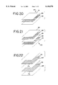
- FIG. 20 discloses an exploded perspective view of a composite material made in accordance with the invention.
- FIG. 21 discloses an exploded perspective view of another embodiment of a composite material made in accordance with the invention.
- FIG. 22 discloses an exploded perspective view of another embodiment of a composite material made in accordance with the invention.
- FIG. 23 discloses a cross sectional view of the composite material of FIG. 20;
- FIG. 24 discloses an enlarged cross sectional view of the composite material of FIG. 23.
- FIG. 25 is a graphic representation of a system for controlling the temperature of separate zones in a mold.
- One embodiment of the present invention is utilized to reinforce and strengthen poles or other structural supports or beams. This is of particular use with wooden utility poles, such as telephone poles or poles supporting power lines. Additionally, poles in the form of concrete columns, such as bridge supports, can be reinforced with this method.
- Wooden utility poles are subject to stress and deterioration which can shorten the useful life of the pole. This is particularly evident at ground level where pressures build due to movement between the exposed, above ground portion of the pole and the fixed, secured portion of the pole below ground. Such movement can be due to wind, or pressure from the telephone or power lines attached to the pole. Additionally, water damage, which may cause rot, is more prevalent at the base of the pole where water can collect and sit for long periods of time. Further, water seeping into the pole can freeze during periods of cold weather causing the pole to expand slightly. This can loosen the pole from the ground when the ice later melts.
- Wooden utility poles are costly and difficult to replace. In fact, many poles are chemically treated and require special handling when removed and replaced with new poles. Accordingly, it is desirable to provide relatively inexpensive structural reinforcement to extend the life of such poles.
- composite materials have been wrapped around the base of such poles, and have then been impregnated on site with a resin system which cures at a relatively low temperature (e.g., about 77° F.) This is typically referred to as an ambient cure system since only ambient temperature is used to cure the resin.
- a sleeve is wrapped around the composite and the resin system is poured into the sleeve. The sleeve is then tightened causing the resin to migrate through the composite material.
- This procedure has several problems since it is dependent on the ambient temperature. If it is too cold, the resin will not cure and may migrate to the bottom of the composite before the temperature rises sufficiently to cure. If it is too hot, the resin may cure before it is in place. Both situations are undesirable.
- FIG. 1 discloses a composite material 10 which can be wrapped around a utility pole 12 to reinforce and strengthen the pole 12.
- the pole is first secured in place by tying securement lines (not shown) to an upper portion of the pole 12 and staking the lines to the ground. Three to four lines in opposed directions are typically sufficient.
- the base of the pole is then evacuated in order to expose about a four foot section of the pole previously underground, and to allow sufficient access to the area to be reinforced (this is one reason it is necessary to first secure the pole)
- a typical utility pole about one third of its length is below ground level.
- the composite material 10 is formed having one or more resin carrying layers and at least one layer of conductive material.
- the conductive layer is formed as an integral component of the composite material 10 prior to the curing operation described below.
- the conductive layer is in a fabric form and comprises a plurality of generally parallel, electrically conductive fibers.
- the composite material 10 is previously impregnated with a heat curable resin system. Preferred forms of the composite material and resin systems are described in greater detail below.
- the composite material 10 is approximately seven feet in length and approximately seven feet wide (for utility poles which have a typical circumference of approximately six feet).
- the composite material 10 includes a first contact 14 and a second contact 15 at either end of the material.
- the contacts 14,15 may be copper bands or other conductive materials, and are in electrical contact with exposed portions of the conductive layer of the composite material. Alternatively, the contacts 14,15 can be added to the composite material 10 after it is secured to the pole 12.
- the composite material 10 is wrapped around the four foot exposed portion of the pole 12 as well as approximately three feet of the pole immediately above ground level.
- the composite material 10 is then secured in place around the pole 12.
- the composite material is secured by stapling it to the pole; however other means, such as, metal bands or plastic ties can be used.
- an inflatable bladder 16 is wrapped around the composite material 10 and secured in place using metal bands 18, or other suitable means such as strips with hook and loop material.
- the bladder is preferably formed from a heat stabilized nylon or silicon film. One such film having 50% nylon #6 and 50% nylon #66 from Allied Signal can be used.
- the bladder 16 includes a nozzle 20 connected to a hose 22 which, in turn, is connected to a pump (not shown). The bladder 16 is inflated to apply approximately 5-10 pounds per square inch of pressure to the composite material 10. This helps insure a tight fit between the composite material 10 and the pole 12 after the resin cures.
- a power generator (not shown) having a first lead 24 and a second lead 26 is provided. As shown in FIG. 3, the first lead 24 is connected to the first contact 14 and the second lead 26 is connected to the; second contact 15 to create an electric circuit. Depending on the size of the bladder, the leads 24,26 from the power generator may have to be connected to the contacts 14,15 before the bladder is put in place.
- the generator is then turned on to cause a current to flow through the conductive layer of the composite material 10 to resistively heat the composite material 10 for a period of 30-90 minutes. A. sufficient current is applied to the conductive layer of the composite material 10 in order to heat the composite material 10 to a temperature to cure the impregnated resin.
- alternating current or direct current may be used, it has been found that direct current provides a more even resistive heating of the composite material.
- One preferred form of a power generator includes a combination of a buck/boost transformer, an auto transformer, a direct current rectified transformer and a VARIAC. These components can be utilized to provide a proper voltage to the conductive layer of the composite material.
- the composite material 10 is preferably raised to 250° F. in order to ensure that there are no cold spots in the composite material during the curing stage.
- the bladder 16 and the leads 24,26 can be removed and the evacuated exposed portion of the pole can be filled in.
- the composite material 10' is approximately 50 feet in length and 30 inches wide.
- the composite material 10' is wrapped around the pole 12' in spirals having approximately 8 inches of overlapping material for each loop around the pole 12'.
- Contacts 24' and 26' are placed at either end of the composite material 10'.
- the second embodiment utilizes more square feet of material than the first embodiment describe above, the resulting structural reinforcement will be stronger than that provided in the first embodiment described above due to the overlapping of the composite material 10'. Additionally, in this form it has been found that only about 7-8 kilowatts of power is required to resistively heat the composite material 10' to cure the resin. Accordingly, a smaller generator is needed to resistively heat the composite material 10'.
- Matched mold halves constructed with a conductive layer similar to the composite materials of the present invention, and designed to have specific thermal and electrical properties can be utilized to effect a more efficient cure and achieve a more uniform part.
- FIG. 7 discloses a cross-section of a mold 30 in an open position having a first mold half or portion 32, and a second mold half or portion 34.
- the mold halves 32,34 are supported and guided by posts 36; however, a clam shell type mold, or other known configurations can be used.
- the mold 30 is configured to hold and compress a part 38 formed from a composite material which includes at least one layer of conductive fibers. The preferred forms of the composite material are described in more detail below.
- each of the mold halves 32,34 include at least one layer of conductive fibers 44,46.
- the conductive layers 44,46 in the mold halves 32,34, along with the conductive layer in the composite material part 38 are utilized to provide resistive heating during the curing process.
- the composite material part 38 may be preimpregnated with a heat curable resin, and then placed in the mold 30.
- the resin may be injected directly into the composite material after the part 38 is placed in the mold 30.
- the mold 30 is equipped with an injection port 48 which is connected by a tube 50 to a reservoir of resin (not shown).
- the mold halves 32,34 are clamped shut as shown in FIG. 8. At this point resin would be injected into the composite material 38 if it was not preimpregnated with the resin.
- a power generator 54 (not shown) is used to supply Current to the conductive layers 44,46 in the mold halves 32,34 and to the conductive layer in the composite material 38.
- the composite material part 38 includes exposed sections 40,42 of the conductive fibers in the part 38 which are placed in line with electrical contacts 52,54 in the mold in order to allow for electrical contact with the power generator 54.
- the mold 30 includes connections so that the conductive layers 44, 46 in the mold 30 and the conductive layer in the composite material 38, are placed in series. Alternatively, separate connections can be made to these layers. This is important when it is necessary to supply different currents to the layers as described below.
- the currents flowing through the conductive layers 44,46 of the mold 30 and the composite material resistively heat the mold and the composite material in order to cure the resin in the material. Once cured, the part may be removed from the mold.
- the mold 30 is constructed from the same or similar material as the composite material part 38. This ensures that the thermal characteristics of the mold 30 match those of the composite material part 38 being cured. This helps ensure a more uniform part production with less rejects. If the thermal characteristics of the mold 30 match that of the part 38 (i.e., have approximately the same coefficient of thermal expansion), then during the curing process where the mold 30 and part 38 are resistively heated, the mold will stay in close contact with the part 38 throughout the process since it will expand and contract at the same rate as the part 38. This ensures that a uniform pressure is applied to the part 38 throughout the curing cycle, and that the part will not pull away from the mold 30 or warp. Such warpage may happen in those cases where the mold does not expand and contract at the same rate as the part 38. By providing conductive layers 44,46 in the mold, this helps ensure that the heat distribution in the mold 30 is similar to that of the part 38.
- the mold 30 is made from a different material if the coefficient of thermal expansion of such material is known.
- the power supplied to the mold 30 is regulated so that the mold 30 heats (or cools after reaching cure temperatures) in manner that the mold 30 expands (or contracts) at the same rate as the composite material part 38.
- molds 30 made in accordance with this embodiment are less expensive than metal molds and require less power to heat.
- Typical structural composite material parts such as boat hulls, trailer side walls, and walls for utility buildings are typically impregnated with a resin system which cures at a low temperature (e.g., 77° F.) and are cured in large open molds which conform to and support the bottom of the part while leaving the top of the part exposed.
- a low temperature e.g., 77° F.
- ambient temperature is used to effect the cure. Since the cure is dependent on ambient temperature, various problems are associated with production of such parts. If the ambient temperature is too cold, the part will not. cure, allowing the resin to migrate to the bottom of the part until raised to a sufficient temperature Alternatively, if the ambient temperature is too hot, the resin will cure before it is thoroughly impregnated in the composite material.
- a higher temperature resin system can be utilized with such parts provided that there is some means to heat the part to a temperature sufficient to cure the resin.
- molds capable of heating such parts are extremely expensive considering the large size of the parts.
- Open molds can be used in combination with copper heating blankets which are placed over the part in the mold.
- this method is undesirable since the heating blankets are cumbersome and require a great deal of power since a large amount of heat is dissipated into the atmosphere.
- the blankets on top of the part they must be kept in place for a long period of time to ensure that the entire part has cured.
- FIG. 9 discloses an open mold 60 having a lower portion 68 configured to support a composite material part 62 in the shape of a boat hull.
- the mold includes electrical contacts 64,66 built into the mold 60 at opposite ends.
- a composite material part 62 which includes a layer of conductive fibers is preformed into the boat hull shape and impregnated with a heat curable resin having a high cure temperature (e.g., 125°-150° F.).
- the conductive fibers are integrally consolidated into the composite material.
- the composite material part 62 is placed in the lower portion 68 of the mold 60.
- the composite material part 62 includes two exposed portions 70,72 of the conductive layer which coincide with the contacts 64,66 in the mold 60.
- a top portion 74 of the mold 60 which supports FL flexible membrane 76 is placed over the composite material part 62.
- a vacuum is created by a pump (not shown) between the membrane and the composite material part 62 through ports (not shown) in the mold 60. The vacuum allows atmospheric pressure to compress and hold the part 62 during the curing operation.
- a power generator (not shown) having first and a second lead 78,80 is connected to the mold 60 so that it is in electrical contact with the conductive fibers in the composite material part 62.
- the power generator is used to cause a current to flow through the conductive fibers of the composite material part 62 sufficient to resistively heat the part 62 to cure the resin.
- the vacuum is released and the finished part is removed from the mold.
- an open mold 82 shown in cross-section in FIGS. 10-11 may include a layer of conductive fibers 85 and is preferably formed from the same material as a composite material part 62' to be cured.
- the open mold 82 also includes electrical contacts 84,86.
- the composite material part 62' includes a layer of conductive fibers and is impregnated with a heat curable resin. The conductive fibers in the composite material part 62' are exposed at either end to coincide with the contacts 84,86.
- a flexible membrane 88 is placed over the part 62' and a vacuum is effected between the part 62' and the membrane 88.
- a power generator (not shown) is connected by leads 90,92 to the mold.
- the generator causes a current to flow through the conductive layer 84 of the mold 82 and the conductive fibers of the composite material part 62' to resistively heat the part 62' to cure the resin.
- the open mold 82 will thermally expand and contract at the same rate as the composite material part to ensure that close contact is maintained between the mold 82 and the part 62' during the cure cycle.
- the mold 60 can be further controlled by providing a plurality of discrete sections or zones of conductive fibers. Each zone can be monitored and separately controlled to achieve a particular temperature. In this manner, the mold 60 can be more readily controlled to match the characteristics of the composite part to enhance the cure. This may advantageous for composite parts having non-uniform shapes, or having portions constructed from different materials. In such instances it may be necessary increase or otherwise vary the temperature of different portions of the mold 60.
- thermocouples connected to each zone of conductive fibers can be used to monitor the temperature of each zone by a computer 180, or microprocessor.
- the computer can also be used to control a temperature controller 182 which in turn controls a power controller 184.
- the power controller can provide different currents to each zone to separately control the temperature of each zone.
- the present invention can also be used to form tubing and other hollow shaped composite material parts.
- FIG. 12-16 disclose a process for forming such parts.
- a composite material part 96 shown in FIG. 12, is preformed into tubular shape and is positioned over an expandable mandrel or bladder 98, shown in FIG. 13.
- the composite material part 96 includes a layer of conductive fibers 100 which are integrally consolidated as part of the composite material.
- the conductive fibers 100 are exposed at opposite ends 99,101 of the part 96, and the composite material is impregnated with a heat curable resin system.
- the mandrel 98 and part 96 are then placed in an outer cylindrical forming shell 102 shown in FIG. 14.
- the shell includes a first portion 104 and a second portion 106 which are secured by clasps 108.
- the mandrel 98 is then inflated through a hose 110, to compress the composite material between the mandrel 98 and the shell 102.
- Electrical contact bands 112,114 of copper, or other suitable conducting material, are connected to the exposed portions 99,101 of the conductive fibers in the composite material part 96.
- a power generator (not shown) is connected to the bands 112,114 by a first and second lead 116,118 to form an electric circuit.
- the generator is utilized to cause an electric current to flow through the conductive fibers 100 of the composite material part 86 to resistively heat the part to cure the impregnated resin.
- the part 96 is removed from the shell 98 and the mandrel 98 is collapsed and removed from the interior of the part 96.
- the part 96 can be injected with a hardening foam, such as an epoxy or urethane or polyester foam.
- This method can also be used to form railroad ties from a composite material by placing the material in an outer shell having a rectangular shape.
- the methods described above can be optimized by orienting the conductive fabric so that the fibers acting as conducting fibers efficiently carry current through the entire composite material part while utilizing the smallest possible contacts.
- further optimization can be obtained by providing a fabric having conducting fibers at an oblique angle with respect to the cross fibers of the fabric.
- the conductive layers are preferably formed from woven conductive materials such as graphite.
- Such woven materials typically are formed on a loom with parallel fibers running in the machine direction, or length of the fabric, and parallel fibers running in the cross-machine direction, or width of the fabric.
- the cross-machine fibers form stitch bonding which holds the fabric together.
- the machine and cross-machine fibers run generally perpendicular to each other.
- either the fibers running in the machine direction or the cross-machine direction can act as conducting fibers to resistively heat the fabric.
- Such fabrics can be oriented to accommodate various shaped composite materials to achieve an effective cure with the smallest possible electric contact, which provides savings in power.
- creating and using fabrics where the machine direction fibers run at an oblique angle with respect to the cross-machine fibers can result in a more efficient use of the fabric.
- This principle can be illustrated by examining a composite material part 120 having a parallelogram shape as shown in FIG. 17, which runs from one side 121 of a rectangular piece of conductive fabric 122 to the other 123. Electrical contacts 124,126 are connected to opposing parallel sides 128,130 of the part 120. The opposing sides 128,130 are smaller than the remaining two sides of the part 132,134, and thus smaller contacts are needed.
- the cross-machine fibers 136 are acting as conducting fibers.
- the cross-machine fibers 136 are perpendicular to the machine fibers 138 of the fabric 122, the effective conductive path through the part 120 is limited, which results in an ineffective cure.
- One way to obtain an effective cure with less power consumption is to orient the fabric 122 so that the cross-machine fibers 136 are parallel to the remaining sides 132,134 of the part 120, as shown in FIG. 18. This provides a conductive path throughout the part 120 while using the contacts 124,126. However, this method requires a wider piece of fabric 140 (shown in phantom) in order to cover the entire part 120.
- An alternative method, which would not require a larger sized fabric, is to create a piece of fabric 142 having conducting fibers oriented at an oblique angle with respect to machine direction fibers such as that shown in FIG. 19. various combinations of these techniques can be used to minimize the number and size of electrical contacts necessary to provide for the most effective conductive path for parts of even more complex shapes,
- the composite materials used in the methods described above are preferably formed from a combination of low-cost resin carrying materials and high performance conductive materials. These materials are consolidated into an integrated composite material.
- FIG. 20 discloses an exploded view of a composite material 150 having a first resin carrying layer 152, a second layer 154 of a conductive material, and a third resin carrying layer 156.
- the conductive second layer 154 is sandwiched between the first and third resin carrying layers 152,156.
- the resin carrying layers 152 and 156 are fabrics made from either 2-4 ounces per square yard of air layered non-woven fiberglass, Kevlar, polyester, or nylon.
- a spun-lace non-woven polyester or nylon fabric is preferred.
- the conductive layer 154 can be formed from several different fabrics having conductive fibers. Factors such as the cost, strength and weight of the finished part can be taken into consideration when deciding on which fabrics are best suited for a particular application.
- One material which may be used is a plan weave graphite fiber fabric. Preferably, the fabric is approximately 6-9 ounces per square yard and includes 10 bundles of graphite fibers per square inch (this is known in the fabric industry as "10pick") where each bundle has approximately 12,000 strands.
- a second fabric which may be utilized is a carbon black glass fabric which is preferably about 12 ounces per square yard.
- a third type of fabric may be used, such as a conductive polymer-coated fabric. Certain such polymers are described in an article by K. F. Schoch, Jr. "Update On Electrically Conductive Polymers and Their Applications” in the IEEE Electrical Insulation Magazine, May/June 1994, Vol. 10, No. 3.
- a unique preferred form of the conductive layer can be formed by combining bundles of graphite fiber and bundles of conductive polymer coated fibers into a single fabric. For instance, five bundles of graphite can be combined with five bundles of polymer coated glass or nylon, to create a fabric having ten bundles per inch.
- the polymer is preferably polypyrrole or polyaniline which have a resistance of approximately 125-175 ohms.
- Such conductive layers are less expensive than pure graphite weaves, and require less current to resistively heat due to the higher resistance of the polymer coated fibers than that of the graphite.
- a second embodiment of a composite material 160 is disclosed in an exploded view in FIG. 21.
- This embodiment includes a first resin carrying layer 162, a second layer 164 of conductive material adjacent the first layer 162, a third resin carrying layer 166 adjacent the second layer 164, a fourth layer 168 of conductive material adjacent the third layer 166, and a fifth resin carrying layer 170 adjacent the fourth layer 168.
- the resin carrying layers and the conductive layers are formed from the same materials as described above. However, due to increased strength achieved in this embodiment, if the conductive layers are the plan graphite weave, it might not be necessary to have ten bundles of fibers per inch of fabric. Fewer bundles, such as six per square inch, may provide satisfactory physical characteristics in the finished composite material part.
- the conductive layers in the composite material 160 can include a plurality of parallel fibers 171 which act as the conducting fibers when electrically resistively heating the composite material.
- the cross or stitch bonding fibers of the fabric may also act as conducting fibers in appropriate circumstances.
- FIG. 22 discloses an exploded view of a modified embodiment of the one disclosed in FIG. 21.
- the second conductive layer 164' includes a plurality of conducting fibers 172 oriented at about a 45° angle with respect to the edge 174 of the layer 172.
- the fourth conductive layer 168' also includes a plurality of parallel conducting fibers 176.
- the conducting fibers 176 in the fourth layer 168' are oriented at about a 135° ngle with respect to the edge 178 of the layer 168'. In this manner, a more effective resistive heat treatment can be utilized to ensure that all areas of the composite material 160 are sufficiently heated to cures impregnated resin. Orientation of the conducting fibers becomes more important as the complexity of the shape of the composite material increases.
- the layers in all three embodiments, disclosed in FIGS. 20-22 are consolidated into a single composite material with the conducting layers being integrally a part of the material. This is preferably done by needle-punching the fabric layers to place a number of fibers 180 in the depth direction of the composite material. This is shown in FIGS. 23 and 24 with respect to the embodiment shown in FIG. 20; however, the embodiments shown in FIGS. 21 and 22 can also be consolidated in the same manner
- size HDB36 needles at 600 penetrations per square inch is sufficient to consolidate the layers.
- the needle size be small enough so that material from the outer layers will fill the barb of the needle. In this manner, the needle will merely push through the conductive layers without substantially disrupting or snagging the electrical path created by the conducting fibers. The greater the penetrations per inch, the flatter the composite material will be.
- the composite material is impregnated with a heat curable resin which is then cured by resistive heat in the manner described above.
- a heat curable resin which is then cured by resistive heat in the manner described above.
- resin systems include either an iso polyester thermosetting resin or vinyl ester resin systems from Reichhold Corporation with an AKZO catalyst, or an epoxy system from Dow Chemical with an Air Products hardener or catalyst.
- resin systems which may be utilized in the embodiments of the invention disclosed above include resins which comprise one or more of: cyanate ester, phenolic, polyurethane, polyvinyle chloride, polycarbonate, polyamide, polyethelene terephthalate, or liquid crystal polymers. Additionally the resin system may include a conductive polymer to assist in generating electrical resistive heat to cure the resin. The polymers can be made electrically conductive by addition of carbon black, nickel, silver or other metals in a powdered form.
- the third resin carrying layers 166 and 166' act as a bulker layer which separates the second 164,164' and fourth 168,168' conductive layers.
- the conductive layer is formed from a high performance fabric such as woven graphite, it functions structurally as a load bearing layer in the composite material 160,160'. Separating the conductive layers has been found to increase the overall strength of the composite above that of a composite material where the two conductive layers are in close contact with each other. Accordingly, this bulker layer can be formed with relatively inexpensive materials while increasing the strength of the finished composite part.
Abstract
Description
Claims (15)
Priority Applications (1)
| Application Number | Priority Date | Filing Date | Title |
|---|---|---|---|
| US08/852,039 US6146576A (en) | 1994-08-08 | 1997-05-06 | Method of forming advanced cured resin composite parts |
Applications Claiming Priority (3)
| Application Number | Priority Date | Filing Date | Title |
|---|---|---|---|
| US08/287,120 US5648137A (en) | 1994-08-08 | 1994-08-08 | Advanced cured resin composite parts and method of forming such parts |
| US46746095A | 1995-06-06 | 1995-06-06 | |
| US08/852,039 US6146576A (en) | 1994-08-08 | 1997-05-06 | Method of forming advanced cured resin composite parts |
Related Parent Applications (1)
| Application Number | Title | Priority Date | Filing Date |
|---|---|---|---|
| US46746095A Continuation | 1994-08-08 | 1995-06-06 |
Publications (1)
| Publication Number | Publication Date |
|---|---|
| US6146576A true US6146576A (en) | 2000-11-14 |
Family
ID=26964263
Family Applications (1)
| Application Number | Title | Priority Date | Filing Date |
|---|---|---|---|
| US08/852,039 Expired - Fee Related US6146576A (en) | 1994-08-08 | 1997-05-06 | Method of forming advanced cured resin composite parts |
Country Status (1)
| Country | Link |
|---|---|
| US (1) | US6146576A (en) |
Cited By (44)
| Publication number | Priority date | Publication date | Assignee | Title |
|---|---|---|---|---|
| US6312247B1 (en) * | 1999-01-29 | 2001-11-06 | Alliant Techsystems Inc. | Vacuum debulking table for thermoplastic materials |
| US6484469B2 (en) * | 2000-10-19 | 2002-11-26 | William E. Drake | Column structures and methods for supporting compressive loads |
| US20020192327A1 (en) * | 1999-12-23 | 2002-12-19 | Roger Amnered | Holding device for holding an article and a plant for heat treatment of an article |
| US20030168164A1 (en) * | 2000-02-03 | 2003-09-11 | Richard Blackmore | Composite structures |
| US20040149733A1 (en) * | 2002-08-15 | 2004-08-05 | Abbott Richard C. | Shaped heaters and uses thereof |
| EP1493545A1 (en) * | 2003-06-30 | 2005-01-05 | Kunststoff-Technik Scherer & Trier GmbH & Co. KG | Airbag cover and process for producing an airbag cover |
| EP1513991A2 (en) * | 2002-05-09 | 2005-03-16 | Forward Ventures, LP | A conductor polymer backfill composition and method of use as a reinforcement material for utility poles |
| US20050140064A1 (en) * | 2003-11-13 | 2005-06-30 | Paul Jorn | Method and apparatus for activating the binder on a semi-finished fiber preform by direct heating of carbon fibers through an applied electrical voltage |
| US20050236098A1 (en) * | 2004-04-26 | 2005-10-27 | Richard Blackmore | Engineered resistive heated complex shape molded composite |
| US20060130993A1 (en) * | 2004-12-22 | 2006-06-22 | General Electric Company | Method for fabricating reinforced composite materials |
| US20060134396A1 (en) * | 2004-12-22 | 2006-06-22 | General Electric Company | Reinforced matrix composite containment duct |
| US20060134251A1 (en) * | 2004-12-22 | 2006-06-22 | General Electric Company | Apparatus for fabricating reinforced composite materials |
| FR2883796A1 (en) * | 2005-04-05 | 2006-10-06 | Jallais Sa | Preformed fiber producing device comprises a polymeric resin puncher integrated to an electric heating system with an electric resistant cable circuit, which is insulated by a sheath |
| WO2008129266A1 (en) * | 2007-04-20 | 2008-10-30 | Dunne Desmond C | Method of coating a surface with sheet moulding compound and surface protection arrangement |
| US20090166935A1 (en) * | 2006-07-06 | 2009-07-02 | Torben Jacob | Method for Producing a Fiber Composite Component for Aerospace |
| US20090218724A1 (en) * | 2008-01-31 | 2009-09-03 | Airbus Deutschland Gmbh | Method for producing a sandwich construction, in particular a sandwich construction for the aeronautical and aerospace fields |
| US20100044912A1 (en) * | 2006-07-06 | 2010-02-25 | Pierre Zahlen | Method For Producing a Fiber Composite Component For Aviation and Spaceflight |
| US20100062099A1 (en) * | 2006-12-07 | 2010-03-11 | Fachhochschule Dortmund | Molding tool for original shaping or reshaping of components composed of materials that can be thermally influenced |
| US20100140448A1 (en) * | 2008-12-10 | 2010-06-10 | General Electric Company | Moulds with integrated heating and methods of making the same |
| US20120288583A1 (en) * | 2011-04-12 | 2012-11-15 | Fundacion Tecnalia Research & Innovation | Device for the preparation of preforms of carbon fiber-reinforced components |
| US20130288036A1 (en) * | 2011-10-06 | 2013-10-31 | Airbus Operation GmbH | Method for connecting fiber-reinforced intermediate products for producing a structural fiber composite product, such a structural fiber composite product and a method and device for producing an adhesive layer |
| US20140030093A1 (en) * | 2011-04-11 | 2014-01-30 | Martin Dahl | Wind turbine blade comprising resistive heating means |
| WO2014107736A1 (en) * | 2013-01-07 | 2014-07-10 | University Of Washington Through Its Center For Commercialization | Embedded section heater for bonding composite structures, and associated apparatuses and methods |
| US20140246138A1 (en) * | 2005-05-30 | 2014-09-04 | Kaneka Corporation | Process for producing graphite film and graphite film produced thereby |
| EP2821201A1 (en) * | 2013-07-05 | 2015-01-07 | Deutsches Zentrum für Luft- und Raumfahrt e.V. | Tempering device for semi-finished fibre products |
| EP2821200A1 (en) * | 2013-07-05 | 2015-01-07 | Deutsches Zentrum für Luft- und Raumfahrt e.V. | Fibre preform tempering device |
| US20150075713A1 (en) * | 2013-09-19 | 2015-03-19 | Siemens Aktiengesellschaft | Method for applying fibre material on a vertical surface |
| US20150251362A1 (en) * | 2014-03-10 | 2015-09-10 | Siemens Aktiengesellschaft | Method and a mold for manufacturing a component for a wind turbine |
| WO2015150515A1 (en) * | 2014-04-03 | 2015-10-08 | Airbus Group Sas | Process and installation for producing a composite material part |
| CN106182828A (en) * | 2016-09-29 | 2016-12-07 | 上海华宜风电模具有限公司 | A kind of blade " work " belly board mold and preparation method thereof |
| US20170057119A1 (en) * | 2015-08-26 | 2017-03-02 | Triumph Integrated Aircraft Interiors, Inc. | Automated press cell system and methods of using the same for forming composite materials |
| CN109414842A (en) * | 2016-05-10 | 2019-03-01 | 罗图公司 | Method and apparatus for heating mould |
| JP2019532847A (en) * | 2016-10-27 | 2019-11-14 | ルアク・シュヴァイツ・アクチェンゲゼルシャフトRuag Schweiz Ag | Fiber reinforced polymer manufacturing |
| US10611097B2 (en) | 2016-05-24 | 2020-04-07 | General Electric Company | Methods and systems including pressurized housings for forming materials |
| US20200123774A1 (en) * | 2017-01-02 | 2020-04-23 | Sabic Global Technologies B.V. | Method for manufacturing a structural beam, structural beam, and building comprising such a beam. |
| ES2766928A1 (en) * | 2018-12-14 | 2020-06-15 | Univ Coruna | PROCEDURE, CONTROL DEVICE AND COMPUTER PROGRAM PRODUCT FOR THE CURING OF A COMPOSITE PIECE (Machine-translation by Google Translate, not legally binding) |
| US10780614B2 (en) | 2016-05-24 | 2020-09-22 | General Electric Company | System and method for forming stacked materials |
| US20210310598A1 (en) * | 2020-04-06 | 2021-10-07 | Creative Pultrusions, Inc. | Fire resistent composite pole system |
| US11407245B1 (en) * | 2021-02-17 | 2022-08-09 | Cricut, Inc. | Sublimation systems and related methods |
| EP4000851A4 (en) * | 2020-08-28 | 2022-08-17 | Mitsubishi Heavy Industries, Ltd. | Composite material molding apparatus and composite material molding method |
| US20230056264A1 (en) * | 2021-08-18 | 2023-02-23 | Mitsubishi Heavy Industries, Ltd. | Composite material processing apparatus and composite material processing method |
| US11648738B2 (en) | 2018-10-15 | 2023-05-16 | General Electric Company | Systems and methods of automated film removal |
| US11691356B2 (en) | 2021-02-08 | 2023-07-04 | General Electric Company | System and method for forming stacked materials |
| US11897277B2 (en) | 2021-02-19 | 2024-02-13 | Cricut, Inc. | Sublimation systems and related methods |
Citations (57)
| Publication number | Priority date | Publication date | Assignee | Title |
|---|---|---|---|---|
| US1960120A (en) * | 1931-03-23 | 1934-05-22 | Firm Saureschutz Ges M B H | Manufacture of articles from synthetic resin compounds |
| US2458864A (en) * | 1945-01-01 | 1949-01-11 | John D Lindsay | Method of making integral molded structures |
| GB945911A (en) * | 1961-04-24 | 1964-01-08 | Ford Motor Co | Improvements in or relating to laminated structures |
| US3346442A (en) * | 1963-12-04 | 1967-10-10 | Robert J Carmody | Honeycomb panel and method of making same |
| US3387333A (en) * | 1965-01-27 | 1968-06-11 | Lockheed Aircraft Corp | Electrically heated mold |
| US3390951A (en) * | 1964-10-05 | 1968-07-02 | Penn Line Service Inc | Strengtheining, preservation, and extension of life of wooden poles |
| US3962394A (en) * | 1975-06-02 | 1976-06-08 | Trw Inc. | Method for molding fiber reinforced composite tube |
| US4199637A (en) * | 1975-11-26 | 1980-04-22 | Shin-Etsu Polymer Co., Ltd. | Anisotropically pressure-sensitive electroconductive composite sheets and method for the preparation thereof |
| JPS5667217A (en) * | 1979-11-08 | 1981-06-06 | Mitsubishi Electric Corp | Molding of composite material |
| US4385957A (en) * | 1979-07-13 | 1983-05-31 | Messerschmitt-Boelkow-Blohm Gmbh | Method for heating a webbing reinforced by carbon fibers |
| JPS6044328A (en) * | 1983-08-22 | 1985-03-09 | Tsunehiko Tsuboi | Method of molding reinforced plastic plate |
| US4510219A (en) * | 1983-11-14 | 1985-04-09 | California Institute Of Technology | Battery plate containing filler with conductive coating |
| US4534886A (en) * | 1981-01-15 | 1985-08-13 | International Paper Company | Non-woven heating element |
| WO1985003906A1 (en) * | 1984-02-29 | 1985-09-12 | Fiber Mechanics Ab | Method and apparatus for producing fiber-reinforced plastics bodies |
| US4560428A (en) * | 1984-08-20 | 1985-12-24 | Rockwell International Corporation | System and method for producing cured composites |
| JPS6118920A (en) * | 1984-07-06 | 1986-01-27 | Yasuhiko Kito | Device for freely attaching detaching contact lens |
| US4568592A (en) * | 1982-10-05 | 1986-02-04 | Shin-Etsu Polymer Co., Ltd. | Anisotropically electroconductive film adhesive |
| EP0173446A1 (en) * | 1984-07-24 | 1986-03-05 | Merseyside And North Wales Electricity Board | Reinforcement of support elements |
| EP0184520A2 (en) * | 1984-12-07 | 1986-06-11 | Constructions Mecaniques De Normandie | Methods of making moulds for hulls and similar thin articles, and moulds obtained thereby |
| US4609449A (en) * | 1982-03-16 | 1986-09-02 | American Cyanamid Company | Apparatus for the production of continuous yarns or tows comprising high strength metal coated fibers |
| US4624751A (en) * | 1983-06-24 | 1986-11-25 | American Cyanamid Company | Process for fiber plating and apparatus with special tensioning mechanism |
| US4661403A (en) * | 1982-03-16 | 1987-04-28 | American Cyanamid Company | Yarns and tows comprising high strength metal coated fibers, process for their production, and articles made therefrom |
| US4668545A (en) * | 1984-09-14 | 1987-05-26 | Raychem Corp. | Articles comprising shaped woven fabrics |
| US4708527A (en) * | 1983-08-19 | 1987-11-24 | Central Plastics Company | Plastic pile protector and method of covering a pile with same |
| US4838971A (en) * | 1987-02-19 | 1989-06-13 | Brunswick Corporation | Filament winding process and apparatus |
| US4861634A (en) * | 1985-12-27 | 1989-08-29 | Coopetanche S.A. | Method for internally lining ducts and sleeves for ducts lined with this method |
| US4874548A (en) * | 1988-03-14 | 1989-10-17 | Ameron, Inc. | Conductive adhesive |
| US4874454A (en) * | 1987-04-24 | 1989-10-17 | Roger Laudy | Decal transfer device |
| US4902215A (en) * | 1988-06-08 | 1990-02-20 | Seemann Iii William H | Plastic transfer molding techniques for the production of fiber reinforced plastic structures |
| US4904351A (en) * | 1982-03-16 | 1990-02-27 | American Cyanamid Company | Process for continuously plating fiber |
| US4909910A (en) * | 1982-03-16 | 1990-03-20 | American Cyanamid | Yarns and tows comprising high strength metal coated fibers, process for their production, and articles made therefrom |
| JPH02150334A (en) * | 1988-11-30 | 1990-06-08 | Tokyo Gas Co Ltd | Device for repairing pipeline partially from inside |
| JPH02158523A (en) * | 1988-12-09 | 1990-06-19 | Tdk Corp | Article transfer device |
| EP0378232A1 (en) * | 1989-01-12 | 1990-07-18 | Mitsubishi Kasei Corporation | Method for reinforcing concrete structures |
| US4966729A (en) * | 1987-04-15 | 1990-10-30 | Le Carbone-Lorraine | Material having a resistivity with a positive temperature coefficient |
| US4972880A (en) * | 1987-06-15 | 1990-11-27 | Insta-Pipe Research Limited Partnership | Pipe liner |
| US4976828A (en) * | 1982-03-16 | 1990-12-11 | American Cyanamid Company | Chaff comprising metal coated fibers |
| US4980008A (en) * | 1989-07-17 | 1990-12-25 | Ball Corporation | Method for decorating cylindrical, metallic containers |
| US4994518A (en) * | 1988-07-13 | 1991-02-19 | Rhone-Poulenc Chimie | Thermotropic polymer/inorganic reinforcing filler molding compositions |
| US4995761A (en) * | 1989-08-23 | 1991-02-26 | Barton Kenneth S | Method and apparatus for repairing ruptures in underground conduits |
| US4997511A (en) * | 1988-05-02 | 1991-03-05 | Newsom Cosby M | Tubular autoclave for curing composite parts |
| US5010440A (en) * | 1988-12-09 | 1991-04-23 | Mamiko Endo | Pipe liner having electrically conductive wires for hardening and electrostatic build-up prevention |
| US5027575A (en) * | 1988-06-14 | 1991-07-02 | Team, Inc. | Method and apparatus for composite pole repair |
| US5043033A (en) * | 1991-01-28 | 1991-08-27 | Fyfe Edward R | Process of improving the strength of existing concrete support columns |
| JPH03212568A (en) * | 1990-01-17 | 1991-09-18 | Mitsubishi Kasei Corp | Reinforcing method for structural member made of concrete |
| US5052906A (en) * | 1989-03-30 | 1991-10-01 | Seemann Composite Systems, Inc. | Plastic transfer molding apparatus for the production of fiber reinforced plastic structures |
| US5147714A (en) * | 1990-11-09 | 1992-09-15 | Abc Industries, Inc. | Antistatic reinforced fabric construction |
| US5182134A (en) * | 1990-11-28 | 1993-01-26 | H. B. Fuller Licensing & Financing Inc. | Radio frequency cure of thermoset-receptor compositions |
| WO1993006410A1 (en) * | 1991-09-13 | 1993-04-01 | Composite Components, Inc. | Method of forming and reforming a plastic composite |
| US5199463A (en) * | 1990-04-05 | 1993-04-06 | Subterra Limited | Method for remotely lining conduits |
| US5248864A (en) * | 1991-07-30 | 1993-09-28 | E. I. Du Pont De Nemours And Company | Method for induction heating of composite materials |
| US5286417A (en) * | 1991-12-06 | 1994-02-15 | International Business Machines Corporation | Method and composition for making mechanical and electrical contact |
| JPH06109194A (en) * | 1992-09-30 | 1994-04-19 | Asahi Tec Corp | Pipe line repairing method |
| US5316462A (en) * | 1993-02-18 | 1994-05-31 | William Seemann | Unitary vacuum bag for forming fiber reinforced composite articles |
| US5326636A (en) * | 1989-11-14 | 1994-07-05 | Poly-Flex Circuits, Inc. | Assembly using electrically conductive cement |
| US5326410A (en) * | 1993-03-25 | 1994-07-05 | Timber Products, Inc. | Method for reinforcing structural supports and reinforced structural supports |
| EP0605085A1 (en) * | 1992-12-29 | 1994-07-06 | SUMIYOSHI MANUFACTURING Co. Ltd. | Method and apparatus for repairing the pipe inner surface by resin coating |
-
1997
- 1997-05-06 US US08/852,039 patent/US6146576A/en not_active Expired - Fee Related
Patent Citations (58)
| Publication number | Priority date | Publication date | Assignee | Title |
|---|---|---|---|---|
| US1960120A (en) * | 1931-03-23 | 1934-05-22 | Firm Saureschutz Ges M B H | Manufacture of articles from synthetic resin compounds |
| US2458864A (en) * | 1945-01-01 | 1949-01-11 | John D Lindsay | Method of making integral molded structures |
| GB945911A (en) * | 1961-04-24 | 1964-01-08 | Ford Motor Co | Improvements in or relating to laminated structures |
| US3346442A (en) * | 1963-12-04 | 1967-10-10 | Robert J Carmody | Honeycomb panel and method of making same |
| US3390951A (en) * | 1964-10-05 | 1968-07-02 | Penn Line Service Inc | Strengtheining, preservation, and extension of life of wooden poles |
| US3387333A (en) * | 1965-01-27 | 1968-06-11 | Lockheed Aircraft Corp | Electrically heated mold |
| US3962394A (en) * | 1975-06-02 | 1976-06-08 | Trw Inc. | Method for molding fiber reinforced composite tube |
| US4199637A (en) * | 1975-11-26 | 1980-04-22 | Shin-Etsu Polymer Co., Ltd. | Anisotropically pressure-sensitive electroconductive composite sheets and method for the preparation thereof |
| US4385957A (en) * | 1979-07-13 | 1983-05-31 | Messerschmitt-Boelkow-Blohm Gmbh | Method for heating a webbing reinforced by carbon fibers |
| JPS5667217A (en) * | 1979-11-08 | 1981-06-06 | Mitsubishi Electric Corp | Molding of composite material |
| US4534886A (en) * | 1981-01-15 | 1985-08-13 | International Paper Company | Non-woven heating element |
| US4661403A (en) * | 1982-03-16 | 1987-04-28 | American Cyanamid Company | Yarns and tows comprising high strength metal coated fibers, process for their production, and articles made therefrom |
| US4609449A (en) * | 1982-03-16 | 1986-09-02 | American Cyanamid Company | Apparatus for the production of continuous yarns or tows comprising high strength metal coated fibers |
| US4904351A (en) * | 1982-03-16 | 1990-02-27 | American Cyanamid Company | Process for continuously plating fiber |
| US4976828A (en) * | 1982-03-16 | 1990-12-11 | American Cyanamid Company | Chaff comprising metal coated fibers |
| US4909910A (en) * | 1982-03-16 | 1990-03-20 | American Cyanamid | Yarns and tows comprising high strength metal coated fibers, process for their production, and articles made therefrom |
| US4568592A (en) * | 1982-10-05 | 1986-02-04 | Shin-Etsu Polymer Co., Ltd. | Anisotropically electroconductive film adhesive |
| US4624751A (en) * | 1983-06-24 | 1986-11-25 | American Cyanamid Company | Process for fiber plating and apparatus with special tensioning mechanism |
| US4708527A (en) * | 1983-08-19 | 1987-11-24 | Central Plastics Company | Plastic pile protector and method of covering a pile with same |
| JPS6044328A (en) * | 1983-08-22 | 1985-03-09 | Tsunehiko Tsuboi | Method of molding reinforced plastic plate |
| US4510219A (en) * | 1983-11-14 | 1985-04-09 | California Institute Of Technology | Battery plate containing filler with conductive coating |
| WO1985003906A1 (en) * | 1984-02-29 | 1985-09-12 | Fiber Mechanics Ab | Method and apparatus for producing fiber-reinforced plastics bodies |
| JPS6118920A (en) * | 1984-07-06 | 1986-01-27 | Yasuhiko Kito | Device for freely attaching detaching contact lens |
| EP0173446A1 (en) * | 1984-07-24 | 1986-03-05 | Merseyside And North Wales Electricity Board | Reinforcement of support elements |
| US4560428A (en) * | 1984-08-20 | 1985-12-24 | Rockwell International Corporation | System and method for producing cured composites |
| US4668545A (en) * | 1984-09-14 | 1987-05-26 | Raychem Corp. | Articles comprising shaped woven fabrics |
| EP0184520A2 (en) * | 1984-12-07 | 1986-06-11 | Constructions Mecaniques De Normandie | Methods of making moulds for hulls and similar thin articles, and moulds obtained thereby |
| US4861634A (en) * | 1985-12-27 | 1989-08-29 | Coopetanche S.A. | Method for internally lining ducts and sleeves for ducts lined with this method |
| US4838971A (en) * | 1987-02-19 | 1989-06-13 | Brunswick Corporation | Filament winding process and apparatus |
| US4966729A (en) * | 1987-04-15 | 1990-10-30 | Le Carbone-Lorraine | Material having a resistivity with a positive temperature coefficient |
| US4874454A (en) * | 1987-04-24 | 1989-10-17 | Roger Laudy | Decal transfer device |
| US4972880A (en) * | 1987-06-15 | 1990-11-27 | Insta-Pipe Research Limited Partnership | Pipe liner |
| US4874548A (en) * | 1988-03-14 | 1989-10-17 | Ameron, Inc. | Conductive adhesive |
| US4997511A (en) * | 1988-05-02 | 1991-03-05 | Newsom Cosby M | Tubular autoclave for curing composite parts |
| US4902215A (en) * | 1988-06-08 | 1990-02-20 | Seemann Iii William H | Plastic transfer molding techniques for the production of fiber reinforced plastic structures |
| US5027575A (en) * | 1988-06-14 | 1991-07-02 | Team, Inc. | Method and apparatus for composite pole repair |
| US4994518A (en) * | 1988-07-13 | 1991-02-19 | Rhone-Poulenc Chimie | Thermotropic polymer/inorganic reinforcing filler molding compositions |
| JPH02150334A (en) * | 1988-11-30 | 1990-06-08 | Tokyo Gas Co Ltd | Device for repairing pipeline partially from inside |
| JPH02158523A (en) * | 1988-12-09 | 1990-06-19 | Tdk Corp | Article transfer device |
| US5010440A (en) * | 1988-12-09 | 1991-04-23 | Mamiko Endo | Pipe liner having electrically conductive wires for hardening and electrostatic build-up prevention |
| EP0378232A1 (en) * | 1989-01-12 | 1990-07-18 | Mitsubishi Kasei Corporation | Method for reinforcing concrete structures |
| US5052906A (en) * | 1989-03-30 | 1991-10-01 | Seemann Composite Systems, Inc. | Plastic transfer molding apparatus for the production of fiber reinforced plastic structures |
| US4980008A (en) * | 1989-07-17 | 1990-12-25 | Ball Corporation | Method for decorating cylindrical, metallic containers |
| US4995761A (en) * | 1989-08-23 | 1991-02-26 | Barton Kenneth S | Method and apparatus for repairing ruptures in underground conduits |
| US5326636A (en) * | 1989-11-14 | 1994-07-05 | Poly-Flex Circuits, Inc. | Assembly using electrically conductive cement |
| JPH03212568A (en) * | 1990-01-17 | 1991-09-18 | Mitsubishi Kasei Corp | Reinforcing method for structural member made of concrete |
| US5199463A (en) * | 1990-04-05 | 1993-04-06 | Subterra Limited | Method for remotely lining conduits |
| US5147714A (en) * | 1990-11-09 | 1992-09-15 | Abc Industries, Inc. | Antistatic reinforced fabric construction |
| US5182134A (en) * | 1990-11-28 | 1993-01-26 | H. B. Fuller Licensing & Financing Inc. | Radio frequency cure of thermoset-receptor compositions |
| US5043033A (en) * | 1991-01-28 | 1991-08-27 | Fyfe Edward R | Process of improving the strength of existing concrete support columns |
| US5248864A (en) * | 1991-07-30 | 1993-09-28 | E. I. Du Pont De Nemours And Company | Method for induction heating of composite materials |
| WO1993006410A1 (en) * | 1991-09-13 | 1993-04-01 | Composite Components, Inc. | Method of forming and reforming a plastic composite |
| US5451351A (en) * | 1991-09-13 | 1995-09-19 | Composite Components, Inc. | Method for rehabilitating a pipe with a liner having an electrically conductive layer |
| US5286417A (en) * | 1991-12-06 | 1994-02-15 | International Business Machines Corporation | Method and composition for making mechanical and electrical contact |
| JPH06109194A (en) * | 1992-09-30 | 1994-04-19 | Asahi Tec Corp | Pipe line repairing method |
| EP0605085A1 (en) * | 1992-12-29 | 1994-07-06 | SUMIYOSHI MANUFACTURING Co. Ltd. | Method and apparatus for repairing the pipe inner surface by resin coating |
| US5316462A (en) * | 1993-02-18 | 1994-05-31 | William Seemann | Unitary vacuum bag for forming fiber reinforced composite articles |
| US5326410A (en) * | 1993-03-25 | 1994-07-05 | Timber Products, Inc. | Method for reinforcing structural supports and reinforced structural supports |
Non-Patent Citations (10)
| Title |
|---|
| "Electrically Conductive Non-Metallic Textile Coatings" by R.V. Gregory, W. C. Kimbrell and H. H. Kuhn, reprinted from Journal Of Coated Fabrics, vol. 20--Jan. 1991. |
| "Processing of Carbon Fiber Reinforced Plastics by Means of Joule Heating" by Hiroshi Fukuda, Adv. Composite Mater., vol. 3, No. 3. pp. 153-161 (1994). |
| "Trickle Impregnating with Polyester Resin to Maximize the Quality of Wound Components in High Volume Production Lines" by Len Goodyer, IEEE Electrical Insulation Magazine Jul./Aug. 1994--vol. 10, No. 4, pp. 6-9. |
| "Update on Electrically Conductive Polymers and Their Applications" by K.F. Schoch, Jr., IEEE Electrical Insulation Magazine May/Jun. 1994--vol. 10, No. 3, pp. 29-32. |
| Electrically Conductive Non Metallic Textile Coatings by R.V. Gregory, W. C. Kimbrell and H. H. Kuhn, reprinted from Journal Of Coated Fabrics, vol. 20 Jan. 1991. * |
| Processing of Carbon Fiber Reinforced Plastics by Means of Joule Heating by Hiroshi Fukuda, Adv. Composite Mater. , vol. 3, No. 3. pp. 153 161 (1994). * |
| The Scrimp Systems advertising brochure. * |
| The Scrimp™ Systems advertising brochure. |
| Trickle Impregnating with Polyester Resin to Maximize the Quality of Wound Components in High Volume Production Lines by Len Goodyer, IEEE Electrical Insulation Magazine Jul./Aug. 1994 vol. 10, No. 4, pp. 6 9. * |
| Update on Electrically Conductive Polymers and Their Applications by K.F. Schoch, Jr., IEEE Electrical Insulation Magazine May/Jun. 1994 vol. 10, No. 3, pp. 29 32. * |
Cited By (80)
| Publication number | Priority date | Publication date | Assignee | Title |
|---|---|---|---|---|
| US6312247B1 (en) * | 1999-01-29 | 2001-11-06 | Alliant Techsystems Inc. | Vacuum debulking table for thermoplastic materials |
| US20020192327A1 (en) * | 1999-12-23 | 2002-12-19 | Roger Amnered | Holding device for holding an article and a plant for heat treatment of an article |
| US6814563B2 (en) * | 1999-12-23 | 2004-11-09 | Saab Ab | Holding device for holding an article and a plant for heat treatment of an article |
| US20030168164A1 (en) * | 2000-02-03 | 2003-09-11 | Richard Blackmore | Composite structures |
| US6484469B2 (en) * | 2000-10-19 | 2002-11-26 | William E. Drake | Column structures and methods for supporting compressive loads |
| EP1513991A4 (en) * | 2002-05-09 | 2007-01-24 | Forward Ventures Lp | A conductor polymer backfill composition and method of use as a reinforcement material for utility poles |
| EP1513991A2 (en) * | 2002-05-09 | 2005-03-16 | Forward Ventures, LP | A conductor polymer backfill composition and method of use as a reinforcement material for utility poles |
| US20040149733A1 (en) * | 2002-08-15 | 2004-08-05 | Abbott Richard C. | Shaped heaters and uses thereof |
| EP1493545A1 (en) * | 2003-06-30 | 2005-01-05 | Kunststoff-Technik Scherer & Trier GmbH & Co. KG | Airbag cover and process for producing an airbag cover |
| US20050079305A1 (en) * | 2003-06-30 | 2005-04-14 | Kunststoff-Technik Scherer & Trier Gmbh & Co Kg | Airbag cover and process for the production of an airbag cover |
| US20050140064A1 (en) * | 2003-11-13 | 2005-06-30 | Paul Jorn | Method and apparatus for activating the binder on a semi-finished fiber preform by direct heating of carbon fibers through an applied electrical voltage |
| US7964131B2 (en) * | 2003-11-13 | 2011-06-21 | Airbus Deutschland Gmbh | Method and apparatus for activating the binder on a semi-finished fiber preform by direct heating of carbon fibers through an applied electrical voltage |
| US20050236098A1 (en) * | 2004-04-26 | 2005-10-27 | Richard Blackmore | Engineered resistive heated complex shape molded composite |
| US20060134251A1 (en) * | 2004-12-22 | 2006-06-22 | General Electric Company | Apparatus for fabricating reinforced composite materials |
| US20060134396A1 (en) * | 2004-12-22 | 2006-06-22 | General Electric Company | Reinforced matrix composite containment duct |
| US7332049B2 (en) | 2004-12-22 | 2008-02-19 | General Electric Company | Method for fabricating reinforced composite materials |
| US7335012B2 (en) | 2004-12-22 | 2008-02-26 | General Electric Company | Apparatus for fabricating reinforced composite materials |
| US7431978B2 (en) | 2004-12-22 | 2008-10-07 | General Electric Company | Reinforced matrix composite containment duct |
| US20060130993A1 (en) * | 2004-12-22 | 2006-06-22 | General Electric Company | Method for fabricating reinforced composite materials |
| US20090142496A1 (en) * | 2004-12-22 | 2009-06-04 | General Electric Company | Method for fabricating reinforced composite materials |
| US7867566B2 (en) | 2004-12-22 | 2011-01-11 | General Electric Company | Method for fabricating reinforced composite materials |
| FR2883796A1 (en) * | 2005-04-05 | 2006-10-06 | Jallais Sa | Preformed fiber producing device comprises a polymeric resin puncher integrated to an electric heating system with an electric resistant cable circuit, which is insulated by a sheath |
| WO2006106195A1 (en) * | 2005-04-05 | 2006-10-12 | Jallais | Laminated heating device and method for producing same |
| US20140246138A1 (en) * | 2005-05-30 | 2014-09-04 | Kaneka Corporation | Process for producing graphite film and graphite film produced thereby |
| US9745196B2 (en) | 2005-05-30 | 2017-08-29 | Kaneka Corporation | Process for producing graphite film and graphite film produced thereby |
| US9512007B2 (en) * | 2005-05-30 | 2016-12-06 | Kaneka Corporation | Process for producing graphite film and graphite film produced thereby |
| US10207463B2 (en) | 2006-07-06 | 2019-02-19 | Airbus Operations Gmbh | Method for producing a fiber composite component for aerospace |
| US9492974B2 (en) * | 2006-07-06 | 2016-11-15 | Airbus Operations Gmbh | Method for producing a fiber composite component for aviation and spaceflight |
| US20090166935A1 (en) * | 2006-07-06 | 2009-07-02 | Torben Jacob | Method for Producing a Fiber Composite Component for Aerospace |
| US20100044912A1 (en) * | 2006-07-06 | 2010-02-25 | Pierre Zahlen | Method For Producing a Fiber Composite Component For Aviation and Spaceflight |
| US20100062099A1 (en) * | 2006-12-07 | 2010-03-11 | Fachhochschule Dortmund | Molding tool for original shaping or reshaping of components composed of materials that can be thermally influenced |
| US8931751B2 (en) * | 2006-12-07 | 2015-01-13 | Fibertemp GmbH & Co.KG | Molding tool for original shaping or reshaping of components composed of materials that can be thermally influenced |
| WO2008129266A1 (en) * | 2007-04-20 | 2008-10-30 | Dunne Desmond C | Method of coating a surface with sheet moulding compound and surface protection arrangement |
| US20090218724A1 (en) * | 2008-01-31 | 2009-09-03 | Airbus Deutschland Gmbh | Method for producing a sandwich construction, in particular a sandwich construction for the aeronautical and aerospace fields |
| US8127450B2 (en) * | 2008-01-31 | 2012-03-06 | Airbus Operations Gmbh | Method for producing a sandwich construction, in particular a sandwich construction for the aeronautical and aerospace fields |
| EP2204247B1 (en) * | 2008-12-10 | 2016-08-24 | General Electric Company | Moulds with integrated heating and methods of making the same |
| US8357325B2 (en) * | 2008-12-10 | 2013-01-22 | General Electric Company | Moulds with integrated heating and methods of making the same |
| US20100140448A1 (en) * | 2008-12-10 | 2010-06-10 | General Electric Company | Moulds with integrated heating and methods of making the same |
| US9719359B2 (en) * | 2011-04-11 | 2017-08-01 | LM WP Patent Holdings A/S | Wind turbine blade comprising resistive heating means |
| US20140030093A1 (en) * | 2011-04-11 | 2014-01-30 | Martin Dahl | Wind turbine blade comprising resistive heating means |
| US20120288583A1 (en) * | 2011-04-12 | 2012-11-15 | Fundacion Tecnalia Research & Innovation | Device for the preparation of preforms of carbon fiber-reinforced components |
| US8764428B2 (en) * | 2011-04-12 | 2014-07-01 | Fundacion Tecnalia Research & Innovation | Device for the preparation of preforms of carbon fiber-reinforced components |
| US9248607B2 (en) * | 2011-10-06 | 2016-02-02 | Airbus Operations Gmbh | Method for connecting fiber-reinforced intermediate products for producing a structural fiber composite product, such a structural fiber composite product and a method and device for producing an adhesive layer |
| US20130288036A1 (en) * | 2011-10-06 | 2013-10-31 | Airbus Operation GmbH | Method for connecting fiber-reinforced intermediate products for producing a structural fiber composite product, such a structural fiber composite product and a method and device for producing an adhesive layer |
| WO2014107736A1 (en) * | 2013-01-07 | 2014-07-10 | University Of Washington Through Its Center For Commercialization | Embedded section heater for bonding composite structures, and associated apparatuses and methods |
| US20150306712A1 (en) * | 2013-01-07 | 2015-10-29 | University Of Washington Through Its Center For Commercialization | Embedded section heater for bonding composite structures, and associated apparatuses and methods |
| EP2821200A1 (en) * | 2013-07-05 | 2015-01-07 | Deutsches Zentrum für Luft- und Raumfahrt e.V. | Fibre preform tempering device |
| EP2821201A1 (en) * | 2013-07-05 | 2015-01-07 | Deutsches Zentrum für Luft- und Raumfahrt e.V. | Tempering device for semi-finished fibre products |
| US20150075713A1 (en) * | 2013-09-19 | 2015-03-19 | Siemens Aktiengesellschaft | Method for applying fibre material on a vertical surface |
| US10479030B2 (en) * | 2013-09-19 | 2019-11-19 | Siemens Gamesa Renewable Energy A/S | Method for applying fibre material on a vertical surface of a web of a wind turbine blade |
| US20150251362A1 (en) * | 2014-03-10 | 2015-09-10 | Siemens Aktiengesellschaft | Method and a mold for manufacturing a component for a wind turbine |
| US10086570B2 (en) * | 2014-03-10 | 2018-10-02 | Siemens Aktiengesellschaft | Method and a mold for manufacturing a component for a wind turbine |
| US10730251B2 (en) | 2014-03-10 | 2020-08-04 | Siemens Gamesa Renewable Energy A/S | Mold for manufacturing a component for a wind turbine |
| FR3019489A1 (en) * | 2014-04-03 | 2015-10-09 | Eads Europ Aeronautic Defence | METHOD AND INSTALLATION FOR CARRYING OUT A COMPOSITE MATERIAL PART |
| WO2015150515A1 (en) * | 2014-04-03 | 2015-10-08 | Airbus Group Sas | Process and installation for producing a composite material part |
| US10596771B2 (en) | 2014-04-03 | 2020-03-24 | Airbus Sas | Process and installation for producing a composite material part |
| US20170057119A1 (en) * | 2015-08-26 | 2017-03-02 | Triumph Integrated Aircraft Interiors, Inc. | Automated press cell system and methods of using the same for forming composite materials |
| CN109414842A (en) * | 2016-05-10 | 2019-03-01 | 罗图公司 | Method and apparatus for heating mould |
| US10780614B2 (en) | 2016-05-24 | 2020-09-22 | General Electric Company | System and method for forming stacked materials |
| US10611097B2 (en) | 2016-05-24 | 2020-04-07 | General Electric Company | Methods and systems including pressurized housings for forming materials |
| CN106182828B (en) * | 2016-09-29 | 2018-11-27 | 北京金风科创风电设备有限公司 | A kind of blade " work " belly board mold and preparation method thereof |
| CN106182828A (en) * | 2016-09-29 | 2016-12-07 | 上海华宜风电模具有限公司 | A kind of blade " work " belly board mold and preparation method thereof |
| JP2019532847A (en) * | 2016-10-27 | 2019-11-14 | ルアク・シュヴァイツ・アクチェンゲゼルシャフトRuag Schweiz Ag | Fiber reinforced polymer manufacturing |
| US11897177B2 (en) * | 2017-01-02 | 2024-02-13 | Sabic Global Technologies B.V. | Method for manufacturing a structural beam, structural beam, and building comprising such a beam |
| US20200123774A1 (en) * | 2017-01-02 | 2020-04-23 | Sabic Global Technologies B.V. | Method for manufacturing a structural beam, structural beam, and building comprising such a beam. |
| US11648738B2 (en) | 2018-10-15 | 2023-05-16 | General Electric Company | Systems and methods of automated film removal |
| WO2020120813A1 (en) * | 2018-12-14 | 2020-06-18 | Universidade Da Coruña | Method, control device and computer program product for the curing of a composite part |
| EP3895868A4 (en) * | 2018-12-14 | 2022-09-21 | Universidade da Coruña | Method, control device and computer program product for the curing of a composite part |
| ES2766928A1 (en) * | 2018-12-14 | 2020-06-15 | Univ Coruna | PROCEDURE, CONTROL DEVICE AND COMPUTER PROGRAM PRODUCT FOR THE CURING OF A COMPOSITE PIECE (Machine-translation by Google Translate, not legally binding) |
| US20210310598A1 (en) * | 2020-04-06 | 2021-10-07 | Creative Pultrusions, Inc. | Fire resistent composite pole system |
| US11686418B2 (en) * | 2020-04-06 | 2023-06-27 | Creative Pultrusions, Inc. | Fire resistant composite pole system |
| US20230272873A1 (en) * | 2020-04-06 | 2023-08-31 | Creative Pultrusions, Inc. | Fire resistent composite pole system |
| EP4000851A4 (en) * | 2020-08-28 | 2022-08-17 | Mitsubishi Heavy Industries, Ltd. | Composite material molding apparatus and composite material molding method |
| US11691356B2 (en) | 2021-02-08 | 2023-07-04 | General Electric Company | System and method for forming stacked materials |
| US20220258514A1 (en) * | 2021-02-17 | 2022-08-18 | Cricut, Inc. | Sublimation Systems and Related Methods |
| US20220324246A1 (en) * | 2021-02-17 | 2022-10-13 | Cricut, Inc. | Sublimation systems and related methods |
| US11407245B1 (en) * | 2021-02-17 | 2022-08-09 | Cricut, Inc. | Sublimation systems and related methods |
| US11932040B2 (en) * | 2021-02-17 | 2024-03-19 | Cricut, Inc. | Sublimation systems and related methods |
| US11897277B2 (en) | 2021-02-19 | 2024-02-13 | Cricut, Inc. | Sublimation systems and related methods |
| US20230056264A1 (en) * | 2021-08-18 | 2023-02-23 | Mitsubishi Heavy Industries, Ltd. | Composite material processing apparatus and composite material processing method |
Similar Documents
| Publication | Publication Date | Title |
|---|---|---|
| US6146576A (en) | Method of forming advanced cured resin composite parts | |
| US5656231A (en) | Method of forming advanced cured resin composite parts | |
| US5451351A (en) | Method for rehabilitating a pipe with a liner having an electrically conductive layer | |
| US7052567B1 (en) | Inflatable heating device for in-situ repair of conduit and method for repairing conduit | |
| US5230844A (en) | Process for producing a complex elastic molded structure of the sandwich type | |
| EP3814673B1 (en) | Composite pressure vessel with reinforced inner liner and process for the production thereof | |
| US6718713B2 (en) | Apparatus and method for joining dissimilar materials to form a structural support member | |
| US6413343B1 (en) | Method for manufacturing hybrid golf club shafts | |
| US4636422A (en) | Composite fiber reinforced molded structure for dimple control | |
| EP2918399B1 (en) | A method for manufacturing a rotor blade for a wind turbine | |
| JP2010509101A (en) | Fiber reinforced composite core and panel | |
| US20050140064A1 (en) | Method and apparatus for activating the binder on a semi-finished fiber preform by direct heating of carbon fibers through an applied electrical voltage | |
| WO2001087571A2 (en) | Composite structures and method for their manufacture | |
| US5749211A (en) | Fiber-reinforced plastic bar and production method thereof | |
| JPH10128860A (en) | Manufacture of fiber-reinforced plastic molded product | |
| JPH09250247A (en) | Composite material reinforced concrete structural body | |
| JP4227299B2 (en) | Manufacturing method of flanged tubular product made of fiber reinforced plastic | |
| JP2008246675A (en) | Inner pressure molding method of frp hollow molded product | |
| JP2009226656A (en) | Internal pressure molding method of frp molded article | |
| JPS6016899B2 (en) | FRP molding method | |
| JPS6347614B2 (en) | ||
| JPS6054181B2 (en) | Manufacturing method of fiber reinforced plastic | |
| JPH03161326A (en) | Pipe fitted with flange made of fiber reinforced composite material and preparation thereof | |
| JP2002248694A (en) | Method for molding fiber reinforced composite material | |
| JP2006218782A (en) | Molding method of molded product made of frp having foam core |
Legal Events
| Date | Code | Title | Description |
|---|---|---|---|
| AS | Assignment |
Owner name: INTRALAMINAR HEAT CURE, INC., D/B/A IHC REHABILITA Free format text: ASSIGNMENT OF ASSIGNORS INTEREST;ASSIGNOR:BLACKMORE, RICHARD D.;REEL/FRAME:010959/0609 Effective date: 20000619 |
|
| FPAY | Fee payment |
Year of fee payment: 4 |
|
| AS | Assignment |
Owner name: VERLINE INSTALLATION, INC., TEXAS Free format text: ASSIGNMENT OF ASSIGNORS INTEREST;ASSIGNORS:BLACKMORE, RICHARD D.;IHC REHABILITATION PRODUCTS, INC.;INTRALAMINAR HEAT CURE, INC.;AND OTHERS;REEL/FRAME:015778/0360 Effective date: 20030701 Owner name: VERLINE, INC., TEXAS Free format text: ASSIGNMENT OF ASSIGNORS INTEREST;ASSIGNORS:BLACKMORE, RICHARD D.;IHC REHABILITATION PRODUCTS, INC.;INTRALAMINAR HEAT CURE, INC.;AND OTHERS;REEL/FRAME:015778/0360 Effective date: 20030701 |
|
| AS | Assignment |
Owner name: VERLINE INC. & VERLINE INSTALLATION INC., TEXAS Free format text: RECORD TO REMOVE 6797358, 5245351 AND 6147576 ON A DOCUMENT PREVIOUSLY RECORDED ON REEL 015778 FRAME 0360;ASSIGNORS:BLACKMORE, RICHARD D.;IHC REHABILITATION PRODUCTS INC.;INTRALAMINER HEAT CURE INC.;AND OTHERS;REEL/FRAME:017015/0402 Effective date: 20030701 |
|
| FEPP | Fee payment procedure |
Free format text: PAT HOLDER NO LONGER CLAIMS SMALL ENTITY STATUS, ENTITY STATUS SET TO UNDISCOUNTED (ORIGINAL EVENT CODE: STOL); ENTITY STATUS OF PATENT OWNER: LARGE ENTITY |
|
| AS | Assignment |
Owner name: ENERGY MAINTENANCE SERVICES GROUP I, LLC, TEXAS Free format text: CONVEYANCE OF 50% INTEREST IN ALL PATENTS AND APPLICATIONS;ASSIGNOR:VERLINE, INCORPORATED;REEL/FRAME:020487/0090 Effective date: 20080129 |
|
| AS | Assignment |
Owner name: ENERGY MAINTENANCE SERVICES GROUP I, LLC, TEXAS Free format text: SUPPLEMENTAL PATENT ASSIGNMENT AGREEMENT;ASSIGNOR:VERLINE, INCORPORATED;REEL/FRAME:020817/0886 Effective date: 20080415 |
|
| REMI | Maintenance fee reminder mailed | ||
| AS | Assignment |
Owner name: ENERGY MAINTENANCE SERVICES GROUP I, LLC, TEXAS Free format text: CORRECTIVE ASSIGNMENT TO CORRECT THE REMOVE THE FOLLOWING DOCUMENTS;ASSIGNOR:VERLINE, INCORPORATED;REEL/FRAME:021450/0834 Effective date: 20080415 |
|
| REIN | Reinstatement after maintenance fee payment confirmed | ||
| FEPP | Fee payment procedure |
Free format text: PETITION RELATED TO MAINTENANCE FEES FILED (ORIGINAL EVENT CODE: PMFP); ENTITY STATUS OF PATENT OWNER: LARGE ENTITY |
|
| FEPP | Fee payment procedure |
Free format text: PETITION RELATED TO MAINTENANCE FEES GRANTED (ORIGINAL EVENT CODE: PMFG); ENTITY STATUS OF PATENT OWNER: LARGE ENTITY |
|
| FP | Lapsed due to failure to pay maintenance fee |
Effective date: 20081114 |
|
| FPAY | Fee payment |
Year of fee payment: 8 |
|
| SULP | Surcharge for late payment | ||
| AS | Assignment |
Owner name: ENERGY MAINTENANCE SERVICES GROUP I, LLC, TEXAS Free format text: ASSIGNMENT OF AN ADDITIONAL UNDIVIDED 25% INTEREST OF ASSIGNOR'S ORIGINAL ENTIRE INTEREST IN ALL PROPERTIES LISTED IN THIS ASSIGNMENT;ASSIGNOR:VERLINE, INCORPORATED;REEL/FRAME:022331/0540 Effective date: 20080415 |
|
| PRDP | Patent reinstated due to the acceptance of a late maintenance fee |
Effective date: 20090331 |
|
| AS | Assignment |
Owner name: VICTORY PARK MANAGEMENT, LLC,ILLINOIS Free format text: SECURITY AGREEMENT;ASSIGNOR:ENERGY MAINTENANCE SERVICES GROUP I, LLC;REEL/FRAME:024066/0250 Effective date: 20100303 Owner name: VICTORY PARK MANAGEMENT, LLC, ILLINOIS Free format text: SECURITY AGREEMENT;ASSIGNOR:ENERGY MAINTENANCE SERVICES GROUP I, LLC;REEL/FRAME:024066/0250 Effective date: 20100303 |
|
| AS | Assignment |
Owner name: VICTORY PARK MANAGEMENT, LLC, AS AGENT, ILLINOIS Free format text: SECURITY AGREEMENT;ASSIGNOR:ENERGY MAINTENANCE SERVICES GROUP I, LLC;REEL/FRAME:027457/0063 Effective date: 20111227 |
|
| AS | Assignment |
Owner name: ENERGY MAINTENANCE SERVICES GROUP I, INC., TEXAS Free format text: CONVERSION FROM A LIMITED LIABILITY COMPANY TO A CORPORATION;ASSIGNOR:ENERGY MAINTENANCE SERVICES GROUP I, LLC;REEL/FRAME:027491/0285 Effective date: 20111230 |
|
| REMI | Maintenance fee reminder mailed | ||
| LAPS | Lapse for failure to pay maintenance fees | ||
| STCH | Information on status: patent discontinuation |
Free format text: PATENT EXPIRED DUE TO NONPAYMENT OF MAINTENANCE FEES UNDER 37 CFR 1.362 |
|
| FP | Lapsed due to failure to pay maintenance fee |
Effective date: 20121114 |