US6147738A - Liquid crystal display device and manufacturing method for same - Google Patents
Liquid crystal display device and manufacturing method for same Download PDFInfo
- Publication number
- US6147738A US6147738A US09/245,907 US24590799A US6147738A US 6147738 A US6147738 A US 6147738A US 24590799 A US24590799 A US 24590799A US 6147738 A US6147738 A US 6147738A
- Authority
- US
- United States
- Prior art keywords
- liquid crystal
- electrically conductive
- adhesive material
- crystal display
- display device
- Prior art date
- Legal status (The legal status is an assumption and is not a legal conclusion. Google has not performed a legal analysis and makes no representation as to the accuracy of the status listed.)
- Expired - Lifetime
Links
Images
Classifications
-
- G—PHYSICS
- G02—OPTICS
- G02F—OPTICAL DEVICES OR ARRANGEMENTS FOR THE CONTROL OF LIGHT BY MODIFICATION OF THE OPTICAL PROPERTIES OF THE MEDIA OF THE ELEMENTS INVOLVED THEREIN; NON-LINEAR OPTICS; FREQUENCY-CHANGING OF LIGHT; OPTICAL LOGIC ELEMENTS; OPTICAL ANALOGUE/DIGITAL CONVERTERS
- G02F1/00—Devices or arrangements for the control of the intensity, colour, phase, polarisation or direction of light arriving from an independent light source, e.g. switching, gating or modulating; Non-linear optics
- G02F1/01—Devices or arrangements for the control of the intensity, colour, phase, polarisation or direction of light arriving from an independent light source, e.g. switching, gating or modulating; Non-linear optics for the control of the intensity, phase, polarisation or colour
- G02F1/13—Devices or arrangements for the control of the intensity, colour, phase, polarisation or direction of light arriving from an independent light source, e.g. switching, gating or modulating; Non-linear optics for the control of the intensity, phase, polarisation or colour based on liquid crystals, e.g. single liquid crystal display cells
- G02F1/133—Constructional arrangements; Operation of liquid crystal cells; Circuit arrangements
- G02F1/1333—Constructional arrangements; Manufacturing methods
- G02F1/1335—Structural association of cells with optical devices, e.g. polarisers or reflectors
- G02F1/133528—Polarisers
-
- G—PHYSICS
- G02—OPTICS
- G02F—OPTICAL DEVICES OR ARRANGEMENTS FOR THE CONTROL OF LIGHT BY MODIFICATION OF THE OPTICAL PROPERTIES OF THE MEDIA OF THE ELEMENTS INVOLVED THEREIN; NON-LINEAR OPTICS; FREQUENCY-CHANGING OF LIGHT; OPTICAL LOGIC ELEMENTS; OPTICAL ANALOGUE/DIGITAL CONVERTERS
- G02F1/00—Devices or arrangements for the control of the intensity, colour, phase, polarisation or direction of light arriving from an independent light source, e.g. switching, gating or modulating; Non-linear optics
- G02F1/01—Devices or arrangements for the control of the intensity, colour, phase, polarisation or direction of light arriving from an independent light source, e.g. switching, gating or modulating; Non-linear optics for the control of the intensity, phase, polarisation or colour
- G02F1/13—Devices or arrangements for the control of the intensity, colour, phase, polarisation or direction of light arriving from an independent light source, e.g. switching, gating or modulating; Non-linear optics for the control of the intensity, phase, polarisation or colour based on liquid crystals, e.g. single liquid crystal display cells
- G02F1/133—Constructional arrangements; Operation of liquid crystal cells; Circuit arrangements
- G02F1/1333—Constructional arrangements; Manufacturing methods
- G02F1/1343—Electrodes
- G02F1/134309—Electrodes characterised by their geometrical arrangement
- G02F1/134363—Electrodes characterised by their geometrical arrangement for applying an electric field parallel to the substrate, i.e. in-plane switching [IPS]
Definitions
- the present invention relates to a liquid crystal display device and a manufacturing method for a liquid crystal display device, and more specifically to a transverse-field type of liquid crystal display in which display abnormalities caused by static electricity and the like are prevented.
- a method of driving a liquid crystal display device that controls the liquid crystal by means of a transverse field is indicated, for example, in the Japanese Unexamined Patent Publication (KOKAI) No. 6-160878. Because a feature of a liquid crystal display of this type is that an electrical field is applied in a direction that is parallel to the surface of the liquid crystal cell, the change in the transmissivity of the liquid crystal cell that occurs when the liquid crystal molecules within the liquid crystal cell surface are twisted being used to make a display, in a liquid crystal display device that includes this liquid crystal cell, it is possible to obtain a clear view of an image, even when viewed at a large viewing angle, thereby enabling the achievement of a viewed displayed which is almost independent of the viewing angle.
- liquid crystal cell In the case of a transverse field type of a liquid crystal cell, because the liquid crystal is control by only an electrical field that is applied between a source electrode and a common electrode that are provided in a comb-like pattern on a TFT substrate, there is no electrode such as an ITO (indium tin oxide) electrode on the opposing color filter substrate film.
- ITO indium tin oxide
- the static electricity of the hand is picked up and passed via the color filter polarizer to the color filter glass substrate, resulting in a potential difference developing between the TFT substrate and the color filter substrate.
- the liquid crystal molecules in response to this potential difference, exhibit faulty behavior and charging occurs.
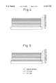
- Another solution method was that of forming an ITO film 27 on the surface of the color filter, using sputtering.
- This method has the drawbacks of (1) a great increase in cost caused by the use of the sputtering method, the same as the above-noted method of solution, and (2) difficulty in removing the adhesive glue that remains on the ITO film 27 when the polarizer is peeled away.
- an object of the present invention is to provide a novel liquid crystal display device which is an improvement over the above-noted drawbacks of the prior art, and which in particular not only prevents abnormal displays caused by static electricity, but also is not damaged by a discharge current occurring during an ESD test, and to provide a method of manufacturing the above-noted liquid crystal display device.
- Another object of the present invention is to provide a liquid crystal display device which does not tend to exhibit a change in visually apparent color of externally applied light, and a method of manufacturing the above-noted liquid crystal display device.
- Yet another object of the present invention is to provide a liquid crystal display device that enables easy exchanging of a polarizer and that is low in cost, and a method of manufacturing the above-noted liquid crystal display device.
- the present invention adopts the following basic technical constitution.
- a first aspect of a liquid crystal display device is a transverse-field type of liquid crystal display device in which a polarizer is adhered to a transparent glass substrate using an adhesive material, wherein electrical conductivity is imparted to said adhesive material, and the resistance value thereof is made to be in the range from 1 ⁇ 10 3 to 1 ⁇ 10 6 ⁇ / ⁇ .
- the above-noted adhesive material is formed in the shape of a mesh or a matrix.
- the first aspect of a method of manufacturing a liquid crystal display device is a method of manufacturing a liquid crystal display device in which a polarizer is adhered to a transparent glass substrate using an adhesive material, wherein electrically conductive particles are dispersed within and held by an acrylic resin, said electrically conductive particles being adjusted so as to be in a weight ratio of 50% to 80% with respect to said acrylic resin, whereby the resistance value of said adhesive material is in the range from 1 ⁇ 10 3 to 1 ⁇ 10 6 ⁇ / ⁇ .
- this method of manufacturing a liquid crystal device is a method of manufacturing a liquid crystal display device in which a polarizer is adhered to a transparent glass substrate using an adhesive material, wherein electrically conductive particles are dispersed within and held by an acrylic resin, the diameter of said electrically conductive particles being made to fall in the range from 0.02 to 2.0 ⁇ m, whereby the resistance value of said adhesive material is in the range from 1 ⁇ 10 3 to 1 ⁇ 10 6 ⁇ / ⁇ .
- this method of manufacturing a liquid crystal device is a method of manufacturing a liquid crystal display device in which a polarizer is adhered to a transparent glass substrate using an adhesive material, wherein electrically conductive particles are dispersed within and held by an acrylic resin, and after application of said adhesive material, the solvent thereof is removed at a temperature in the range from 75° C. to 85° C. whereby the resistance value of said adhesive material is in the range from 1 ⁇ 10 3 to 1 ⁇ 10 6 ⁇ / ⁇ .
- the electrically conductive particles are electrically conductive inorganic metallic particles such as ITO, ZnO 2 , or Sn 2 O 3 .
- the electrically conductive particles are electrically conductive organic particles such as polythiophene or polypyrol.
- the electrically conductive particles are formed by a spin-coat method, a dip-coat method, a bar-coat method, or an offset printing method.
- a liquid crystal display device is a liquid crystal display device having a polarizer adhered to a transparent substrate with an adhesive material therebetween, electrical conductivity being imparted to the adhesive material, which has a resistance value in the range from 1 ⁇ 10 3 to 1 ⁇ 10 6 ⁇ / ⁇ .
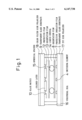
- FIG. 1 is a cross-sectional view of a liquid crystal display device according to the present invention.
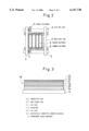
- FIG. 2 is a cross-sectional view of a liquid crystal display device according to the present invention that shows an enlarged view of a pixel.
- FIG. 3 is a cross-sectional view that shows the condition of a polarizer adhered to a transparent substrate by an intervening layer of adhesive, according to the present invention.
- FIG. 4 is a cross-sectional view that shows the prior art.
- FIG. 5 is a cross-sectional view that shows another example of the prior art.
- FIG. 1 through FIG. 3 show the construction of a specific example of the present invention, this being method of manufacturing a liquid crystal display device having a polarizer 18 that is adhered to a transparent substrate 9 via an adhesive material 24, whereby electrically conductive particles are dispersed into and held by an acrylic resin to form the above-noted adhesive material, these electrically conductive particles being adjusted so as to be in a weight ratio of 50% to 80% with respect to the acrylic resin, so that the sheet resistance value of the adhesive material is in the range from 1 ⁇ 10 3 to 1 ⁇ 10 6 ⁇ / ⁇ .
- FIG. 1 is a cross-sectional view of a liquid crystal display device according to the present invention
- FIG. 2 is a detailed drawing of an active element pixel of a liquid crystal display device according to the present invention
- FIG. 3 is a detailed drawing of the cross-sectional structure of the polarizer in a liquid crystal display device according to the present invention.
- a drain bus line 2 and a gate bus line 3 are respectively formed vertically and horizontally on the transparent glass substrate 1, and the drain bus line 2 is connected to the source electrode 5, via the switching element 4.
- the common electrode 6 and the source electrode 5 are formed in the shape of mutually opposing comb teeth, the orientation condition of the liquid crystal being controlled by the electric field that is applied between these two electrodes.
- a protective insulation film 7 is formed so as to cover these electrodes, and above this an orientation film 8 is formed.
- a black matrix 10 in the form of a matrix, is formed onto the transparent glass substrate 9, colored layers 11 of red, green, and blue being formed as a slab so as to cover the area therebetween.
- a transparent protective film 12 is formed, over which an orientation film 13 is formed.
- a liquid crystal 14 having a positive dielectric constant anisotropy is sandwiched in the space between and held by the two above-noted transparent glass substrates 1 and 9, orientation being made via the orientation films 8 and 13, so that the liquid crystal 14 is approximately parallel to the two transparent glass substrates 1 and 9.
- Spherical spacers 15 are held within the display area and rod-shaped spacers are held in the peripheral seal area 16 in the non-display area to control the cell thickness of the liquid crystal 14.
- the polarizers 17 and 18 are attached to the side of the transparent glass substrates 1 and 9 that make contact with the liquid crystal 14 and on the opposites sides thereof.
- the polarizers 17 and 18 are in the so-called crossed Nicols orientation, so that the transparent axes thereof are mutually perpendicular.
- the transparent axis of the polarizer 17 is oriented at a prescribed angle so as to coincide with the orientation direction of the liquid crystal 14, and the transparent axis of the other polarizer 18 is oriented so as to be perpendicular to the transparent axis of the polarizer 17.
- a polarizer 19 is held between two triacetyl cellulose (TAC) films 20 and 21, and an anti-glare layer 22, which has been anti-contamination and anti-glare treated, is formed on the surface of one of the TAC films 21, and over this a protective film 23 is adhered.
- TAC triacetyl cellulose
- an electrically conductive adhesive material 24 is provide, and the polarizer 17,18 are respectively adhered the transparent glass substrates 1 and 9.
- a chromium film is formed on the transparent glass substrate 1, using sputtering, and photolithography is used to perform patterning of a gate bus line 3 and a common electrode 6 in the desired shapes.
- the CVD process is used to form a gate insulation film made of silicon nitride and a switching element 4 made of amorphous silicon.
- Sputtering and photolithography are used to form a drain bus line 2 and a source electrode 5 made of chromium so as to cover part of the switching element 4, and onto the top of this a protective insulation film 7 made of silicon nitride is formed.
- an orientation film 8 made chiefly of polyimide (for example, the SUNEVER Series made by Nissan Kagaku), is formed in the desired pattern, using offset printing or other such transfer method, onto the these electrode.
- a rubbing roll made of rayon or the like is used to perform orientation in a direction that makes an angle of 15 degrees with respect to the source electrode 5.
- a black matrix 10 made of either two layers of chromium or a black organic resin, is patterned in the shape of a matrix, by using photolithograpy, so as to cover the gate bus line 3 and the drain bus line 2.
- colored layers 11 consisting of three colors of organic dye, that is, R (red), G (green), and B (blue) are patterned in a striped configuration using photolithography.
- a protective film 12, made of a transparent acrylic resin or the like, is formed for the purpose of preventing staining from impurities from these colored layers 11 and the purpose of providing flatness.
- the orientation film 13 is formed using the method described above, and orientation is imparted in a direction that makes an angle of 15 degrees with respect to the strip direction of the colored layers 11.
- the transparent glass substrates 1 and 9, which have been fabricated up through the steps of orientation, are caused to oppose one another in parallel orientation, spherical spacers having a diameter of 5.5 ⁇ m are distributed within the display area in which the black matrix 10 and colored layers 11 exist, and an epoxy sealant which includes 7.0 ⁇ m rod-shaped spacers being used in the non-display area.
- the inside of the liquid crystal cell has sealed in it a nematic liquid crystal 14 (for example, the RIKUSON series made by Chisso Co., Ltd.) having a dielectric constant anisotropy of 4.5 and a birefringence ⁇ n of 0.067.
- the electrically conductive adhesive material 24 is adjusted according to the following method.
- Electrically conductive inorganic metallic particles such as ITO (indium tin oxide), ZnO 2 , or Sn 2 O 3 are dispersed into and held by an acrylic resin to form an electrically conductive adhesive material 24.
- the diameter of these electrically conductive inorganic metallic particles are smaller than the SiO 2 (silicon oxide) particles used in the anti-glare layer 22, this being 2 ⁇ m or less and desirably set in the range from 0.02 to 2 ⁇ m, the weight ratio of (electrically conductive inorganic metallic particles)/(acrylic resin) being 50% to 80%.
- the resistance value of the electrically conductive adhesive material 24 is established in the range from 1 ⁇ 10 3 to 1 ⁇ 10 6 ⁇ / ⁇ .
- the electrically conductive adhesive material 24, which contains these inorganic materials, is applied to the bottom surface of the TAC film 20, which is the base film, using a spin-coat method, a dip-coat method, or a bar-coat method. It is also possible to use an offset printing method or the like to provide the electrically conductive adhesive material 24 in the pattern of a mesh or matrix.
- the solvent in this example, the acrylic resin
- the resistance value is lowered more than in the case of drying at room temperature.
- methods which can be envisioned of controlling the resistance value of the electrically conductive adhesive material 24 include (1) a method of changing the amount of inorganic conductive material, (2) a method of changing the diameter of the electrically conductive particles, and (3) a method of changing the temperature at which the solvent into which the electrically conductive inorganic material was dispersed is removed.
- a PVA (polyvinyl alcohol) polymer that is made by absorption orientation of iodine or a dichroic dye is held between the two TAC films 20 and 21 to form the polarizer 19.
- the anti-glare layer 22 has particles of SiO 2 or the like dispersed therein, and to prevent the accumulation of fingerprints and the like, a fluorine coating is applied onto the surface thereof.
- a peelable protective film 23 is applied. The protective film 23 is peeled away at the final process step in fabricating the module.
- the thicknesses of the above-noted films were approximately 10 ⁇ m for the polarizer 19, approximately 80 ⁇ m for the two TAC films 20 and 21 that hold the polarizer 19 between them, 10 ⁇ m or so for the anti-glare layer 22, approximately 100 ⁇ m for the protective film 23, and approximately 20 ⁇ m for the electrically conductive adhesive layer 24.
- a driving method for controlling a liquid crystal by the transverse field method such as in the present invention is that of applying an electrical field in a direction that is parallel to the transparent substrate, so that the liquid crystal is twisted thereby, so as to change the transmissivity of the liquid crystal.
- the molecules of the liquid crystal 14 are at a small angle with respect to the comb-tooth-shaped source electrode 5 and common electrode 6 longitudinal direction. That is, the orientation is such that the angle formed between the long axis of the molecules of the liquid crystal 14 (the optical axis) and the direction of the electrical field (which is perpendicular to the longitudinal direction of the source electrode 5 and the common electrode 6) is 45 degrees or greater, but less than 90 degrees. In this condition, because the birefringence of the molecules of the liquid crystal 14 is zero, the transmitted light intensity is zero.
- a voltage is applied to the gate bus line 3 and the switching element 4 is turned on, a voltage is applied to the source electrode 5, so that an electrical field is applied between the source electrode 5 and the common electrode 6, the orientation of the molecules of the liquid crystal 14 changing to that of the direction of this electrical field.
- the transmission axes of the polarizers 17 and 18 that are positioned on the outside of the two transparent glass substrates 1 and 9 are in crossed Nicols orientation, enabling a change in the intensity of the transmitted light (transmissivity).
- the reason for this is that, by imparting electrical conductivity to the adhesive material 24 of the polarizer 18, such as is done in a liquid crystal display device according to the present invention, and by also connecting this to ground, the electrical charge that is imparted from the surface of the polarizer 18 is led to ground via this electrically conductive adhesive material 24, so that a potential difference does not develop between the two transparent glass substrates 1 and 9, and the liquid crystal 14 that is sealed between these substrates is not affected by a vertically oriented electrical field.
- the above-noted ESD test is a test that is performed by setting the surface of the polarizer 18 to the ground potential and applying a voltage from the tip of a probe of (10 kV ten times at an interval of 1 second, after which observation is made as to the degree of charge-up, and the damage condition at the surface of the polarizer 18 that was contacted by the probe tip.
- the layer to which electrically conductivity is imparted is within the adhesive material layer, making it difficult to reflect external light.
- an electrically conductive material such as ITO is formed on the surface of the polarizer, when external light is reflected at the surface of the polarizer, it is affected by the diameter of the particles of ITO and the thickness of the film, this resulting in a change in the color appearance, making it look bluish or reddish.
- the layer to which electrical conductivity is imparted is not on the surface of the polarizer but rather within the adhesive material layer, because the color appearance of the reflected light is determined by the condition of the surface, the reflected light is not affected by the diameter of the particles or the film thickness, the result being no change in the appearance of the display.
- Another feature of the present invention is that the method of imparting the electrically conductive material is low in cost.
- the method of the present invention is that of using a spin-coat or dip-coat method to form an electrically conductive material within the adhesive material, this enabling a great reduction in cost.
- Another feature of the present invention is that it is easy to exchange the polarizer that is adhered to the transparent glass substrate 9.
- an electrically conductive organic material such as polythiophene or polypyrol is chemically polymerized and dispersed into an acrylic resin, this being used as the electrically conductive adhesive material 24.
- the resistance value of the resulting electrically conductive adhesive material 24 is adjusted to within the range from 1 ⁇ 10 3 to 1 ⁇ 10 6 ⁇ / ⁇ .
- An electrically conductive material 24 that includes these electrically conductive organic materials is formed on the bottom surface of the TAC film 20, that is the base film, using a spin-coat method, a dip-coat method, or a bar coat method of application thereto. It is also possible to use an offset printing method to form the electrically conductive adhesive material 24 in a mesh or matrix pattern.
- the solvent is removed at a high temperature of approximately to 80° C. When the solvent is removed, there is a tendency for the resistance value to be lowered more than in the case of drying at room temperature.
- methods that can be envisioned of controlling the resistance value of the electrically conductive adhesive material 24 include (1) a method of changing the content of inorganic conductive material, and (2) a method of changing the temperature at which the solvent into which the electrically conductive inorganic material was dispersed is removed.
- FIG. 1 shows the constitution of a liquid crystal display device as described above, this device achieving the following effects.
- the first effect is that even if a static electricity charge of a high voltage is imparted to the liquid crystal display device by contact by the hand of the polarizer or some other reason, there is no accumulation of the static electricity on the liquid crystal display device and, for this reason, an abnormal display is prevented.
- the second effect is that damage is not incurred from the discharge current occurring when an ESD test is performed.
- the third effect is that there is no tendency for the color appearance by external light to change, so that the appearance of the display does not change.
- the fourth effect is that, because the electrically conductive material is formed within the adhesive material by using a spin-coat or dip-coat method, manufacturing is done at a low cost.
- the fifth effect is that it is easy to exchange a polarizer after it is adhered to a transparent glass substrate.
Abstract
Description
Claims (8)
Applications Claiming Priority (2)
| Application Number | Priority Date | Filing Date | Title |
|---|---|---|---|
| JP02699298A JP3165100B2 (en) | 1998-02-09 | 1998-02-09 | Liquid crystal display device and manufacturing method thereof |
| JP10-026992 | 1998-02-09 |
Publications (1)
| Publication Number | Publication Date |
|---|---|
| US6147738A true US6147738A (en) | 2000-11-14 |
Family
ID=12208667
Family Applications (1)
| Application Number | Title | Priority Date | Filing Date |
|---|---|---|---|
| US09/245,907 Expired - Lifetime US6147738A (en) | 1998-02-09 | 1999-02-08 | Liquid crystal display device and manufacturing method for same |
Country Status (6)
| Country | Link |
|---|---|
| US (1) | US6147738A (en) |
| EP (1) | EP0935157B1 (en) |
| JP (1) | JP3165100B2 (en) |
| KR (1) | KR100294522B1 (en) |
| DE (1) | DE69931672T2 (en) |
| TW (1) | TW554215B (en) |
Cited By (38)
| Publication number | Priority date | Publication date | Assignee | Title |
|---|---|---|---|---|
| US6392727B1 (en) * | 1998-12-31 | 2002-05-21 | Honeywell International Inc. | Reduced reflectance polarized display |
| US20030001989A1 (en) * | 2001-03-05 | 2003-01-02 | Seiichi Kusumoto | Polarizing plate and liquid crystal display using the same |
| US6512562B1 (en) * | 1999-04-15 | 2003-01-28 | Konica Corporation | Protective film for polarizing plate |
| US6525793B2 (en) * | 1998-07-16 | 2003-02-25 | Nec Corporation | Liquid crystal display apparatus |
| US20030058391A1 (en) * | 2001-09-26 | 2003-03-27 | Nitto Denko Corporation | Semi-transmitting reflective plate, reflective plate, semi-transmitting polarizer, reflective polarizer and liquid crystal display using same |
| US6556263B2 (en) * | 2000-02-18 | 2003-04-29 | Lg.Philips Lcd Co., Ltd. | In-plane switching color LCD panel implementing electro-conductive polarizer and fabricating method thereof |
| US20030122997A1 (en) * | 2001-12-31 | 2003-07-03 | Noh Jeong Dong | Conductive polarizer of liquid crystal display device |
| US20040114070A1 (en) * | 2002-12-12 | 2004-06-17 | Hsin-Tao Huang | Liquid crystal display module |
| US20040141135A1 (en) * | 2001-03-06 | 2004-07-22 | Seiko Epson Corporation | Liquid crystal device, projection type display and electronic equipment |
| US6838185B2 (en) * | 2001-11-27 | 2005-01-04 | Nitto Denko Corporation | Adhesive used for polarizing plate and optical member |
| US20050063057A1 (en) * | 2003-09-23 | 2005-03-24 | Optimax Technology Corporation | Polarizer to improve contrast for liquid crystal display from down view angle |
| US20050117216A1 (en) * | 2003-11-29 | 2005-06-02 | Pavonine Inc., Of Incheon, Republic Of Korea | 3D display apparatus |
| US20050185105A1 (en) * | 2004-01-20 | 2005-08-25 | Sharp Kabushiki Kaisha | Display element and display device |
| US20060146235A1 (en) * | 2004-12-31 | 2006-07-06 | Oh Kwang S | Color filter substrate for liquid crystal display and method of fabricating the same |
| US20060176423A1 (en) * | 2005-02-04 | 2006-08-10 | Lee Jae-Ho | Polarizer and liquid crystal display using such a polarizer |
| US20070023751A1 (en) * | 2005-07-26 | 2007-02-01 | Tdk Corporation | Thin film device, thin film device module, and method of forming thin film device module |
| US20070070282A1 (en) * | 2005-09-20 | 2007-03-29 | Sharp Kabushiki Kaisha | Display panel and display device |
| KR100732815B1 (en) * | 2001-01-13 | 2007-06-27 | 가부시키가이샤 아리사와 세이사쿠쇼 | Manufacturing method for a 3d image display member and film for forming a 3d image display member |
| US20070182886A1 (en) * | 2000-01-20 | 2007-08-09 | International Business Machines Corporation | Liquid crystal display panel and device thereof |
| US20070247710A1 (en) * | 2004-06-15 | 2007-10-25 | Dai Nippon Printing Co., Ltd. | Antistatic Laminated Body and Polarizing Plate Using the Same |
| US20080284970A1 (en) * | 2007-05-18 | 2008-11-20 | Semiconductor Energy Laboratory Co., Ltd. | Liquid crystal display device and manufacturing method thereof |
| US20090002615A1 (en) * | 2007-06-15 | 2009-01-01 | Semiconductor Energy Laboratory Co., Ltd. | Display device |
| US20090091693A1 (en) * | 2006-03-24 | 2009-04-09 | Akinori Izumi | Display panel, display panel fabrication method and removal apparatus |
| US20090279009A1 (en) * | 2008-05-12 | 2009-11-12 | Epson Imaging Devices Corporation | Liquid crystal display panel and method for manufacturing the same |
| US20100276696A1 (en) * | 2000-04-27 | 2010-11-04 | Semiconductor Energy Laboratory Co., Ltd. | Semiconductor Device and Method of Fabricating the Same |
| US20110032456A1 (en) * | 2009-08-04 | 2011-02-10 | Hitachi Displays, Ltd. | Display device |
| US20110063244A1 (en) * | 2009-09-17 | 2011-03-17 | Innocom Technology (Shenzhen) Co., Ltd. | Optical film and display module using the same |
| US20110181813A1 (en) * | 2008-07-18 | 2011-07-28 | Lg Chem, Ltd. | Polarization plate and liquid crystal display |
| US20120314276A1 (en) * | 2010-01-26 | 2012-12-13 | Satoyuki Nomura | Light control film |
| US20150177562A1 (en) * | 2013-12-20 | 2015-06-25 | Apple Inc. | Electronic Device Display With Damage-Resistant Polarizer |
| US20150277110A1 (en) * | 2014-03-27 | 2015-10-01 | Samsung Display Co., Ltd. | Display device and method of manufacturing the same |
| US20150309215A1 (en) * | 2014-04-24 | 2015-10-29 | Boe Technology Group Co., Ltd. | Polarizing Sheet, Substrate Structure And Display Panel |
| US20160334669A1 (en) * | 2015-05-14 | 2016-11-17 | Shenzhen China Star Optoelectronics Technology Co. Ltd. | Polarizing plate and liquid crystal display panel |
| US20170017026A1 (en) * | 2014-03-31 | 2017-01-19 | Fujifilm Corporation | Polarizing plate, image display device, and liquid crystal display device |
| US20170261806A1 (en) * | 2015-08-25 | 2017-09-14 | Boe Technology Group Co., Ltd. | Display Substrate |
| US20190114457A1 (en) * | 2016-08-08 | 2019-04-18 | Boe Technology Group Co., Ltd. | Fingerprint identification display panel and display device |
| CN110050252A (en) * | 2016-10-31 | 2019-07-23 | 康宁股份有限公司 | The method that the unit of uneven effect with reduction embeds combining display and reduces uneven effect |
| US11200400B2 (en) | 2018-06-15 | 2021-12-14 | Shenzhen GOODIX Technology Co., Ltd. | Fingerprint identification apparatus and electronic device |
Families Citing this family (12)
| Publication number | Priority date | Publication date | Assignee | Title |
|---|---|---|---|---|
| JP2002014628A (en) * | 2000-04-27 | 2002-01-18 | Semiconductor Energy Lab Co Ltd | Semiconductor device and its manufacturing method |
| JP4811973B2 (en) * | 2001-01-23 | 2011-11-09 | 日東電工株式会社 | Adhesive optical film |
| KR101128016B1 (en) | 2004-06-15 | 2012-03-29 | 다이니폰 인사츠 가부시키가이샤 | Antistatic laminated body and polarizing plate using the same |
| KR100732834B1 (en) * | 2005-12-28 | 2007-06-27 | 삼성에스디아이 주식회사 | 2d and 3d image selectable display device |
| KR100803782B1 (en) * | 2006-09-28 | 2008-02-15 | 율촌화학 주식회사 | Surface protective film |
| JP2008185935A (en) * | 2007-01-31 | 2008-08-14 | Seiko Instruments Inc | Display device |
| CN201025489Y (en) * | 2007-03-20 | 2008-02-20 | 叶隆泰 | Non static polarized slice |
| KR20100009472A (en) | 2008-07-18 | 2010-01-27 | 주식회사 엘지화학 | Liquid crystal display |
| JP2010181429A (en) * | 2009-02-03 | 2010-08-19 | Hitachi Displays Ltd | Liquid crystal display |
| JP5354691B2 (en) * | 2010-12-10 | 2013-11-27 | 日東電工株式会社 | Adhesive layer |
| JP5758135B2 (en) * | 2011-01-28 | 2015-08-05 | 日立マクセル株式会社 | Liquid crystal display |
| JP6892248B2 (en) * | 2016-11-15 | 2021-06-23 | 三菱電機株式会社 | Liquid crystal display device |
Citations (7)
| Publication number | Priority date | Publication date | Assignee | Title |
|---|---|---|---|---|
| JPH0451220A (en) * | 1990-06-19 | 1992-02-19 | Sharp Corp | Liquid crystal display device |
| JPH06160878A (en) * | 1992-09-18 | 1994-06-07 | Hitachi Ltd | Liquid crystal display device |
| JPH06313807A (en) * | 1993-04-28 | 1994-11-08 | Sumitomo Chem Co Ltd | Polarizing plate |
| JPH0990391A (en) * | 1995-09-20 | 1997-04-04 | Casio Comput Co Ltd | Liquid crystal display device |
| JPH09105918A (en) * | 1995-10-12 | 1997-04-22 | Hitachi Ltd | Liquid crystal display device |
| JPH09269507A (en) * | 1996-03-29 | 1997-10-14 | Hosiden Corp | Liquid crystal display element |
| US5870160A (en) * | 1995-10-12 | 1999-02-09 | Hitachi, Ltd. | In-plane field type liquid crystal display device comprising a structure which is prevented from charging with electricity |
Family Cites Families (5)
| Publication number | Priority date | Publication date | Assignee | Title |
|---|---|---|---|---|
| JPS6267515A (en) * | 1985-09-20 | 1987-03-27 | Fujitsu Ltd | Liquid crystal display element |
| JPH0460512A (en) * | 1990-06-28 | 1992-02-26 | Sharp Corp | Liquid crystal display device |
| JP3051233B2 (en) * | 1991-11-15 | 2000-06-12 | オプトレックス株式会社 | Negative liquid crystal display device |
| JPH0821989A (en) * | 1994-07-08 | 1996-01-23 | Hitachi Ltd | Liquid crystal display element and its production |
| JPH10268783A (en) * | 1997-03-26 | 1998-10-09 | Hitachi Ltd | Picture display device |
-
1998
- 1998-02-09 JP JP02699298A patent/JP3165100B2/en not_active Expired - Lifetime
-
1999
- 1999-02-03 TW TW088101646A patent/TW554215B/en not_active IP Right Cessation
- 1999-02-08 KR KR1019990004279A patent/KR100294522B1/en not_active IP Right Cessation
- 1999-02-08 DE DE69931672T patent/DE69931672T2/en not_active Expired - Lifetime
- 1999-02-08 US US09/245,907 patent/US6147738A/en not_active Expired - Lifetime
- 1999-02-08 EP EP99102420A patent/EP0935157B1/en not_active Expired - Lifetime
Patent Citations (7)
| Publication number | Priority date | Publication date | Assignee | Title |
|---|---|---|---|---|
| JPH0451220A (en) * | 1990-06-19 | 1992-02-19 | Sharp Corp | Liquid crystal display device |
| JPH06160878A (en) * | 1992-09-18 | 1994-06-07 | Hitachi Ltd | Liquid crystal display device |
| JPH06313807A (en) * | 1993-04-28 | 1994-11-08 | Sumitomo Chem Co Ltd | Polarizing plate |
| JPH0990391A (en) * | 1995-09-20 | 1997-04-04 | Casio Comput Co Ltd | Liquid crystal display device |
| JPH09105918A (en) * | 1995-10-12 | 1997-04-22 | Hitachi Ltd | Liquid crystal display device |
| US5870160A (en) * | 1995-10-12 | 1999-02-09 | Hitachi, Ltd. | In-plane field type liquid crystal display device comprising a structure which is prevented from charging with electricity |
| JPH09269507A (en) * | 1996-03-29 | 1997-10-14 | Hosiden Corp | Liquid crystal display element |
Cited By (81)
| Publication number | Priority date | Publication date | Assignee | Title |
|---|---|---|---|---|
| US6525793B2 (en) * | 1998-07-16 | 2003-02-25 | Nec Corporation | Liquid crystal display apparatus |
| US6392727B1 (en) * | 1998-12-31 | 2002-05-21 | Honeywell International Inc. | Reduced reflectance polarized display |
| US7428030B2 (en) | 1999-04-15 | 2008-09-23 | Konica Corporation | Protective film for polarizing plate |
| US6512562B1 (en) * | 1999-04-15 | 2003-01-28 | Konica Corporation | Protective film for polarizing plate |
| US20070058111A1 (en) * | 1999-04-15 | 2007-03-15 | Konica Corporation | Protective film for polarizing plate |
| US7738056B2 (en) | 2000-01-20 | 2010-06-15 | International Business Machines Corporation | Liquid crystal display panel and device thereof |
| US20080309845A1 (en) * | 2000-01-20 | 2008-12-18 | International Business Machines Corporation | Liquid crystal display panel and device thereof |
| US20070182886A1 (en) * | 2000-01-20 | 2007-08-09 | International Business Machines Corporation | Liquid crystal display panel and device thereof |
| US20080062346A1 (en) * | 2000-01-20 | 2008-03-13 | International Business Machines Corporation | Liquid crystal display panel and device thereof |
| US7561228B2 (en) | 2000-01-20 | 2009-07-14 | International Business Machines Corporation | Liquid crystal display panel and device thereof |
| US7355662B2 (en) * | 2000-01-20 | 2008-04-08 | International Business Machines Corporation | Liquid crystal display panel and device thereof |
| US7450195B2 (en) | 2000-01-20 | 2008-11-11 | International Business Machines Corporation | Liquid crystal display panel and device thereof |
| US6556263B2 (en) * | 2000-02-18 | 2003-04-29 | Lg.Philips Lcd Co., Ltd. | In-plane switching color LCD panel implementing electro-conductive polarizer and fabricating method thereof |
| US20100276696A1 (en) * | 2000-04-27 | 2010-11-04 | Semiconductor Energy Laboratory Co., Ltd. | Semiconductor Device and Method of Fabricating the Same |
| US9780124B2 (en) | 2000-04-27 | 2017-10-03 | Semiconductor Energy Laboratory Co., Ltd. | Display device including pixel comprising first transistor second transistor and light-emitting element |
| US9419026B2 (en) | 2000-04-27 | 2016-08-16 | Semiconductor Energy Laboratory Co., Ltd. | Semiconductor device and method of fabricating the same |
| US8633488B2 (en) | 2000-04-27 | 2014-01-21 | Semiconductor Energy Laboratory Co., Ltd. | Semiconductor device and method of fabricating the same |
| US8178880B2 (en) | 2000-04-27 | 2012-05-15 | Semiconductor Energy Laboratory Co., Ltd. | Semiconductor device and method of fabricating the same |
| US9099361B2 (en) | 2000-04-27 | 2015-08-04 | Semiconductor Energy Laboratory Co., Ltd. | Semiconductor device and method of fabricating the same |
| KR100732815B1 (en) * | 2001-01-13 | 2007-06-27 | 가부시키가이샤 아리사와 세이사쿠쇼 | Manufacturing method for a 3d image display member and film for forming a 3d image display member |
| US6882385B2 (en) | 2001-03-05 | 2005-04-19 | Nitto Denko Corporation | Polarizing plate having protective films with plasticizer, liquid crystal display using the same, and methods of making the same |
| US6847419B2 (en) * | 2001-03-05 | 2005-01-25 | Nitto Denko Corporation | Polarizing plate and liquid crystal display using the same |
| US20030001989A1 (en) * | 2001-03-05 | 2003-01-02 | Seiichi Kusumoto | Polarizing plate and liquid crystal display using the same |
| US20040137224A1 (en) * | 2001-03-05 | 2004-07-15 | Nitto Denko Corporation | Polarizing plate and liquid crystal display using the same |
| US20040141135A1 (en) * | 2001-03-06 | 2004-07-22 | Seiko Epson Corporation | Liquid crystal device, projection type display and electronic equipment |
| US7609352B2 (en) | 2001-03-06 | 2009-10-27 | Seiko Epson Corporation | Liquid crystal device, projection type display and electronic equipment |
| US20050275785A1 (en) * | 2001-03-06 | 2005-12-15 | Seiko Epson Corporation | Liquid crystal device, projection type display and electronic equipment |
| US7251008B2 (en) | 2001-03-06 | 2007-07-31 | Seiko Epson Corporation | Liquid crystal device, projection type display and electronic equipment |
| US7196760B2 (en) * | 2001-03-06 | 2007-03-27 | Seiko Epson Corporation | Liquid crystal device, projection type display and electronic equipment |
| US20070206144A1 (en) * | 2001-03-06 | 2007-09-06 | Seiko Epson Corporation | Liquid crystal device, projection type display and electronic equipment |
| US7411646B2 (en) | 2001-03-06 | 2008-08-12 | Seiko Epson Corporation | Liquid crystal device, projection type display and electronic equipment |
| US20030058391A1 (en) * | 2001-09-26 | 2003-03-27 | Nitto Denko Corporation | Semi-transmitting reflective plate, reflective plate, semi-transmitting polarizer, reflective polarizer and liquid crystal display using same |
| US6965418B2 (en) | 2001-09-26 | 2005-11-15 | Nitto Denko Corporation | Semi-transmitting reflective plate, reflective plate, semi-transmitting polarizer, reflective polarizer and liquid crystal display using same |
| US6838185B2 (en) * | 2001-11-27 | 2005-01-04 | Nitto Denko Corporation | Adhesive used for polarizing plate and optical member |
| US6809783B2 (en) * | 2001-12-31 | 2004-10-26 | Boe-Hydis Technology Co., Ltd. | Conductive polarizer of liquid crystal display device |
| US20030122997A1 (en) * | 2001-12-31 | 2003-07-03 | Noh Jeong Dong | Conductive polarizer of liquid crystal display device |
| US20040114070A1 (en) * | 2002-12-12 | 2004-06-17 | Hsin-Tao Huang | Liquid crystal display module |
| US6956699B2 (en) * | 2003-09-23 | 2005-10-18 | Optimax Technology Corporation | Polarizer to improve contrast for liquid crystal display from down view angle |
| US20050063057A1 (en) * | 2003-09-23 | 2005-03-24 | Optimax Technology Corporation | Polarizer to improve contrast for liquid crystal display from down view angle |
| US7268943B2 (en) * | 2003-11-29 | 2007-09-11 | Pavonine Inc. | 3D display apparatus |
| US20050117216A1 (en) * | 2003-11-29 | 2005-06-02 | Pavonine Inc., Of Incheon, Republic Of Korea | 3D display apparatus |
| US20050185105A1 (en) * | 2004-01-20 | 2005-08-25 | Sharp Kabushiki Kaisha | Display element and display device |
| US20100149480A1 (en) * | 2004-01-20 | 2010-06-17 | Koichi Miyachi | Display device producing display by changing shape of refractive index ellipsoid of medium by applying electric field to medium |
| US7724335B2 (en) | 2004-01-20 | 2010-05-25 | Sharp Kabushiki Kaisha | Display device producing display by changing shape of refractive index ellipsoid of medium by applying electric field to medium |
| US20070247710A1 (en) * | 2004-06-15 | 2007-10-25 | Dai Nippon Printing Co., Ltd. | Antistatic Laminated Body and Polarizing Plate Using the Same |
| US20100259711A1 (en) * | 2004-06-15 | 2010-10-14 | Dai Nippon Printing Co., Ltd. | Antistatic laminated body and polarizing plate using the same |
| US20060146235A1 (en) * | 2004-12-31 | 2006-07-06 | Oh Kwang S | Color filter substrate for liquid crystal display and method of fabricating the same |
| US20060176423A1 (en) * | 2005-02-04 | 2006-08-10 | Lee Jae-Ho | Polarizer and liquid crystal display using such a polarizer |
| US7355261B2 (en) * | 2005-07-26 | 2008-04-08 | Tdk Corporation | Thin film device, thin film device module, and method of forming thin film device module |
| US20070023751A1 (en) * | 2005-07-26 | 2007-02-01 | Tdk Corporation | Thin film device, thin film device module, and method of forming thin film device module |
| US8120746B2 (en) | 2005-09-20 | 2012-02-21 | Sharp Kabushiki Kaisha | Display panel and display device having medium whose optical anisotropy magnitude changes according to electric field |
| US20070070282A1 (en) * | 2005-09-20 | 2007-03-29 | Sharp Kabushiki Kaisha | Display panel and display device |
| US20090091693A1 (en) * | 2006-03-24 | 2009-04-09 | Akinori Izumi | Display panel, display panel fabrication method and removal apparatus |
| CN101410746B (en) * | 2006-03-24 | 2012-11-21 | 夏普株式会社 | Display panel, process for producing display panel, and removal apparatus |
| US8325310B2 (en) * | 2007-05-18 | 2012-12-04 | Semiconductor Energy Laboratory Co., Ltd. | Liquid crystal display device and manufacturing method thereof |
| US20080284970A1 (en) * | 2007-05-18 | 2008-11-20 | Semiconductor Energy Laboratory Co., Ltd. | Liquid crystal display device and manufacturing method thereof |
| US20090002615A1 (en) * | 2007-06-15 | 2009-01-01 | Semiconductor Energy Laboratory Co., Ltd. | Display device |
| US8154675B2 (en) * | 2008-05-12 | 2012-04-10 | Sony Corporation | Liquid crystal display panel and method for manufacturing the same |
| US20090279009A1 (en) * | 2008-05-12 | 2009-11-12 | Epson Imaging Devices Corporation | Liquid crystal display panel and method for manufacturing the same |
| US8717518B2 (en) * | 2008-07-18 | 2014-05-06 | Lg Chem, Ltd. | Polarization plate and liquid crystal display |
| US20110181813A1 (en) * | 2008-07-18 | 2011-07-28 | Lg Chem, Ltd. | Polarization plate and liquid crystal display |
| US8755012B2 (en) | 2009-08-04 | 2014-06-17 | Japan Display Inc. | Display device |
| US20110032456A1 (en) * | 2009-08-04 | 2011-02-10 | Hitachi Displays, Ltd. | Display device |
| US20110063244A1 (en) * | 2009-09-17 | 2011-03-17 | Innocom Technology (Shenzhen) Co., Ltd. | Optical film and display module using the same |
| US8570642B2 (en) * | 2010-01-26 | 2013-10-29 | Hitachi Chemical Company, Ltd. | Light control film |
| US20120314276A1 (en) * | 2010-01-26 | 2012-12-13 | Satoyuki Nomura | Light control film |
| US9316860B2 (en) * | 2013-12-20 | 2016-04-19 | Apple Inc. | Electronic device display with damage-resistant polarizer |
| US20150177562A1 (en) * | 2013-12-20 | 2015-06-25 | Apple Inc. | Electronic Device Display With Damage-Resistant Polarizer |
| US10241325B2 (en) * | 2014-03-27 | 2019-03-26 | Samsung Display Co., Ltd. | Display device and method of manufacturing the same |
| US20150277110A1 (en) * | 2014-03-27 | 2015-10-01 | Samsung Display Co., Ltd. | Display device and method of manufacturing the same |
| US10545332B2 (en) | 2014-03-27 | 2020-01-28 | Samsung Display Co., Ltd. | Display device and method of manufacturing the same |
| US20170017026A1 (en) * | 2014-03-31 | 2017-01-19 | Fujifilm Corporation | Polarizing plate, image display device, and liquid crystal display device |
| US20150309215A1 (en) * | 2014-04-24 | 2015-10-29 | Boe Technology Group Co., Ltd. | Polarizing Sheet, Substrate Structure And Display Panel |
| US20160334669A1 (en) * | 2015-05-14 | 2016-11-17 | Shenzhen China Star Optoelectronics Technology Co. Ltd. | Polarizing plate and liquid crystal display panel |
| US10209557B2 (en) * | 2015-08-25 | 2019-02-19 | Boe Technology Group Co., Ltd. | Display substrate |
| US20170261806A1 (en) * | 2015-08-25 | 2017-09-14 | Boe Technology Group Co., Ltd. | Display Substrate |
| US20190114457A1 (en) * | 2016-08-08 | 2019-04-18 | Boe Technology Group Co., Ltd. | Fingerprint identification display panel and display device |
| US10467452B2 (en) * | 2016-08-08 | 2019-11-05 | Boe Technology Group Co., Ltd. | Fingerprint identification display panel and display device |
| CN110050252A (en) * | 2016-10-31 | 2019-07-23 | 康宁股份有限公司 | The method that the unit of uneven effect with reduction embeds combining display and reduces uneven effect |
| US11200400B2 (en) | 2018-06-15 | 2021-12-14 | Shenzhen GOODIX Technology Co., Ltd. | Fingerprint identification apparatus and electronic device |
| US11295110B2 (en) | 2018-06-15 | 2022-04-05 | Shenzhen GOODIX Technology Co., Ltd. | Under-screen biometric identification apparatus and electronic device |
Also Published As
| Publication number | Publication date |
|---|---|
| TW554215B (en) | 2003-09-21 |
| JP3165100B2 (en) | 2001-05-14 |
| KR19990072487A (en) | 1999-09-27 |
| EP0935157A3 (en) | 2001-01-31 |
| EP0935157A2 (en) | 1999-08-11 |
| DE69931672T2 (en) | 2007-05-31 |
| KR100294522B1 (en) | 2001-07-12 |
| DE69931672D1 (en) | 2006-07-20 |
| EP0935157B1 (en) | 2006-06-07 |
| JPH11223827A (en) | 1999-08-17 |
Similar Documents
| Publication | Publication Date | Title |
|---|---|---|
| US6147738A (en) | Liquid crystal display device and manufacturing method for same | |
| JP2701698B2 (en) | Liquid crystal display | |
| CN100580526C (en) | Liquid crystal display device and method of fabricating the same | |
| KR100327613B1 (en) | Liquid crystal display device | |
| JP2701832B2 (en) | Liquid crystal display | |
| KR100366835B1 (en) | Liquid crystal display device of latitudinal electric field type having protruded spacer | |
| JP3085633B2 (en) | Reflective liquid crystal display | |
| KR100479433B1 (en) | Liquid crystal display device and manufacturing method thereof | |
| JP2009037154A (en) | Liquid crystal display device | |
| JP2000292801A (en) | Liquid crystal display device | |
| KR101074395B1 (en) | In-Plane Switching mode Liquid Crystal Display Device | |
| US20050219442A1 (en) | Color filter on array mode liquid crystal display and method for making the same | |
| JP3799287B2 (en) | Evaluation method of liquid crystal display device | |
| JPH04309925A (en) | Active matrix color liquid crystal display element | |
| US5847793A (en) | Liquid crystal display apparatus and fabrication process thereof | |
| KR20090010528A (en) | Substrate for display panel and liquid crystal display panel with the same | |
| JP2000066222A (en) | Active matrix liquid crystal display device | |
| JP3987142B2 (en) | Liquid crystal device | |
| KR100390703B1 (en) | Liquid crystal display device | |
| US7369197B2 (en) | Polarizer, panel for a liquid crystal display, and liquid crystal display, including a scattering layer | |
| JPH07261169A (en) | Liquid crystal display device | |
| JPH11337734A (en) | Conductive polarizing plate | |
| KR20080044579A (en) | Liquid crystal display panel and a fabricating method with the same | |
| JP3613807B2 (en) | Color polarizing filter and liquid crystal display device using the same | |
| JP2001066586A (en) | Liquid crystal display device |
Legal Events
| Date | Code | Title | Description |
|---|---|---|---|
| AS | Assignment |
Owner name: NEC CORPORATION, JAPAN Free format text: ASSIGNMENT OF ASSIGNORS INTEREST;ASSIGNOR:OKAMOTO, MAMORU;REEL/FRAME:009762/0955 Effective date: 19981126 |
|
| STCF | Information on status: patent grant |
Free format text: PATENTED CASE |
|
| FEPP | Fee payment procedure |
Free format text: PAYOR NUMBER ASSIGNED (ORIGINAL EVENT CODE: ASPN); ENTITY STATUS OF PATENT OWNER: LARGE ENTITY |
|
| AS | Assignment |
Owner name: NEC LCD TECHNOLOGIES, LTD., JAPAN Free format text: ASSIGNMENT OF ASSIGNORS INTEREST;ASSIGNOR:NEC CORPORATION;REEL/FRAME:014108/0248 Effective date: 20030401 |
|
| FPAY | Fee payment |
Year of fee payment: 4 |
|
| FPAY | Fee payment |
Year of fee payment: 8 |
|
| AS | Assignment |
Owner name: NLT TECHNOLOGIES, LTD., JAPAN Free format text: CHANGE OF NAME;ASSIGNOR:NEC LCD TECHNOLOGIES, LTD.;REEL/FRAME:027188/0738 Effective date: 20110701 |
|
| FPAY | Fee payment |
Year of fee payment: 12 |