US6147983A - Telecommunications systems - Google Patents
Telecommunications systems Download PDFInfo
- Publication number
- US6147983A US6147983A US08/995,543 US99554397A US6147983A US 6147983 A US6147983 A US 6147983A US 99554397 A US99554397 A US 99554397A US 6147983 A US6147983 A US 6147983A
- Authority
- US
- United States
- Prior art keywords
- time slots
- transceivers
- transceiver
- verification device
- verification
- Prior art date
- Legal status (The legal status is an assumption and is not a legal conclusion. Google has not performed a legal analysis and makes no representation as to the accuracy of the status listed.)
- Expired - Lifetime
Links
Images
Classifications
-
- H—ELECTRICITY
- H04—ELECTRIC COMMUNICATION TECHNIQUE
- H04W—WIRELESS COMMUNICATION NETWORKS
- H04W36/00—Hand-off or reselection arrangements
- H04W36/06—Reselecting a communication resource in the serving access point
-
- H—ELECTRICITY
- H04—ELECTRIC COMMUNICATION TECHNIQUE
- H04W—WIRELESS COMMUNICATION NETWORKS
- H04W88/00—Devices specially adapted for wireless communication networks, e.g. terminals, base stations or access point devices
- H04W88/08—Access point devices
-
- H—ELECTRICITY
- H04—ELECTRIC COMMUNICATION TECHNIQUE
- H04W—WIRELESS COMMUNICATION NETWORKS
- H04W24/00—Supervisory, monitoring or testing arrangements
- H04W24/04—Arrangements for maintaining operational condition
-
- H—ELECTRICITY
- H04—ELECTRIC COMMUNICATION TECHNIQUE
- H04W—WIRELESS COMMUNICATION NETWORKS
- H04W36/00—Hand-off or reselection arrangements
- H04W36/34—Reselection control
- H04W36/38—Reselection control by fixed network equipment
Definitions
- This invention relates to a base station, and to a base station transceiver, and in particular to a method of operation thereof, for use in a mobile communications system.
- the invention relates to the efficient utilisation of the base station resources.
- each base station typically includes several transceiver devices. Decisions regarding hand-offs are based on measurements performed by the mobile, and verifications performed by the base stations.
- Each active mobile is continuously measuring signal strength on frequencies transmitted from neighbouring base stations. The values are reported to the system, which keeps a list of potential target cells for hand-off, in the event that the quality of the current connection falls below an acceptable level. When this happens, the system may decide that, in order to improve the connection quality, a hand-off should be performed. The system then chooses a target cell from the list, and orders the chosen target cell to verify that the mobile is detectible with acceptable quality, in order to ensure that the connection quality will be acceptable after hand-off. This procedure may be repeated with other target cells, until an acceptable target cell is found.
- the verifications are performed by a dedicated transceiver device located in each base station.
- the dedicated verification device is often referred to as a VER-device, while the transceiver devices which carry the control channels and traffic channels are often referred to as DVC-devices.
- a small base station may have three DVC-devices and one VER-device, which means that 25% of the hardware cost of the base station is the cost of the VER-device, since the VER-device and the DVC-devices are of comparable complexity.
- the VER-device tunes its receiver to the frequency used by the mobile, and first searches for the synchronisation sequence, which differentiates the specific mobile with which it is concerned from other mobiles using the other time slots on the same frequency.
- the VER-device searches for the digital voice channel colour code, or DVCC, to verify that it is receiving a signal from the intended mobile. A determination can then be made as to the quality of the connection.
- the verification procedure can then be repeated, in order to be able to compensate for effects such as fading and shadowing.
- An object of the present invention is to allow at least one device in a base station to be used for performing verifications as well as for carrying traffic channels, thereby reducing or eliminating the cost of hardware which is dedicated to the performance of verifications.
- a further problem which arises with known base stations is that, from time to time, it is necessary to clear traffic from one of the transceiver devices, for example to allow new software to be loaded, or to perform maintenance. This can only be done by blocking all current calls on that device.
- An object of the present invention is to allow a transceiver device to be blocked, without requiring any current calls to be terminated.
- a first aspect of the invention relates to a base station, and a method of operation thereof, in which a transceiver device which performs verifications is also able to handle traffic calls.
- a transceiver device which is to be blocked is able to hand-off calls to other transceiver devices within the base station.
- transceiver device which performs verifications is also able to handle traffic calls, and that device is carrying traffic calls but other transceiver devices within the base station have free time slots, that transceiver device is able to hand-off calls to the other transceiver devices.
- FIG. 1 is a schematic representation of a base station in accordance with the invention.
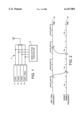
- FIG. 2 is a time history of the operating frequency of a transceiver device operating in accordance with the first aspect of the invention.
- FIG. 1 shows a base station 2 in accordance with the invention.
- the advantages of the present invention are particularly noticeable when applied to small base stations, and the base station 2 is a pico base station for use in an indoor cellular system, but it will be appreciated that the invention is applicable to any base station.
- the base station includes four transceivers 4, 6, 8, 10.
- Transceivers 4, 6, 8 are used for traffic channels, and for the digital control channel.
- each transceiver device operates on a respective different frequency, in three time slots, with each time slot being allocated either to a traffic channel or to the digital control channel.
- These transceivers 4, 6, 8 are also referred to as transceivers TRX1, TRX2 and TRX3 respectively.
- the fourth transceiver 10 also has a respective operating frequency allocated to it, and is also divided into three time slots. This device is also used for performing verifications when necessary, and is also referred to herein as VER/TRX 4.
- the transceivers are connected to an antenna arrangement 12, and controlled by a base station controller 14.
- such a base station would be able to handle a maximum of 8 traffic channels (three time slots on each of TRX1, TRX2 and TRX3, with one time slot being reserved for the digital control channel), while in accordance with the present invention the base station can handle up to 11 traffic channels, without requiring additional hardware, since three traffic channels can also be allocated to VER/TRX4.
- the digital control channel (DCC) is allocated to one of the transceivers 4, 6, 8, for example to time slot 1 of TRX1.
- transceivers TRX1, TRX2 and TRX3 when there are 8 or fewer mobiles connected to the base station, they are allocated to transceivers TRX1, TRX2 and TRX3.
- Table 1 shows a situation in which mobiles DVC1 and DVC2 are allocated to time slots 2 and 3 respectively of TRX1; mobiles DVC3, DVC4 and DVC5 are allocated to time slots 1, 2 and 3 respectively of TRX2; and mobile DVC6 is allocated to time slot 1 of TRX3.
- Time slots 2 and 3 on TRX3 are unallocated, and the fourth transceiver VER/TRX4 is free to perform verifications, as in the prior art.
- Table 2 shows the situation when mobiles DVC7 and DVC8 have been connected to the base station, in time slots 2 and 3 respectively of TRX3.
- the fourth transceiver VER/TRX4 still carries no traffic channels, and is available to perform verifications as required.
- VER/TRX4 When further mobiles are connected to the base station, they are allocated to the fourth transceiver device VER/TRX4, which then has to act in a very similar way to the other transceivers, for most of the time. For example, it has a frequency specifically allocated to it. Table 3 below shows the situation in which mobiles DVC9 and DVC10 have been connected to time slots 1 and 2 respectively of VER/TRX4, while time slot 3 remains free.
- FIG. 2 shows the time histories of transmissions on two frequencies.
- the upper line represents transmissions on the operating frequency of the VER/TRX4 device.
- the frequency has three time slots, a first of which is allocated to DVC9, a second of which is allocated to DVC10, and the third of which is free.
- the lower line in FIG. 2 represents transmissions on the frequency of a target mobile device, for which the base station is now required to perform a verification, to determine whether that mobile device should hand-off to the base station.
- the frequency of the mobile device also has three time slots, one of which is allocated to the mobile device mx. It will be appreciated that other mobile devices may be allocated to the other two time slots. In both the upper and lower lines, three time slots form a frame, lasting 20 ms.
- the device VER/TRX4 in normal operation, that is when not performing verifications, the device VER/TRX4 is operating on its own allocated frequency, handling traffic from mobiles DVC9 and DVC10. At time t1, a verification is ordered, to determine whether the further mobile device mx should be allocated to the base station. At this point, the device VER/TRX4 retunes its receiver to the frequency of the target mobile device, which it reaches at time t2. The transceiver VER/TRX4 then remains tuned to the frequency of the target mobile device for at least one frame period, i.e. 20 ms in the illustrated embodiment, to ensure that it receives a signal from the target mobile mx.
- the VER/TRX4 device searches for the mobile using the synchronisation sequence, and detects the DVCC. Signal strength measurements are then used by the base station controller 14 to make the required verification. If desired, the system can be set such that the VER/TRX4 device is tuned to the target mobile frequency for a longer period, for example to allow repetition of the verification, to improve the reliability thereof.
- the VER/TRX4 device retunes to its own operating frequency, which it reaches at time t4.
- the device which is handling traffic channels is also able to perform verifications.
- the VER/TRX4 device is unable to handle traffic, which means that one or two time slots for DVC9 and DVC10 are lost. However, this is unlikely to be noticed by users.
- Table 4 below shows the situation in which a further mobile station DVC11 has been allocated to time slot 3 of VER/TRX4.
- the device VER/TRX4 would only rarely be used for traffic channels, since the system capacity should be such that normal loads can be handled by the other transceivers TRX1, TRX2 and TRX3. Nevertheless, it is an advantage to be able to use a fourth transceiver to handle calls at peak times.
- Table 5 below shows a situation after a period of peak traffic loading has just ended, and the situation is returning to normal.
- this aspect of the invention allows more traffic to be handled by a base station.
- base stations may be designed to use less hardware than conventionally.
- a further aspect of the invention relates to the general use of intra-cell hand-off, as described above with reference to Table 5.
- Table 6 shows a situation in which time slot 1 of TRX1 is being used for the digital control channel (DCC); mobiles DVC1 and DVC2 are allocated to time slots 2 and 3 of TRX1; mobiles DVC3 and DVC4 are allocated to time slots 1 and 2 of TRX2; and mobile DVC5 is allocated to time slot 1 of TRX3.
- DCC digital control channel
- mobiles DVC1 and DVC2 are allocated to time slots 2 and 3 of TRX1
- mobiles DVC3 and DVC4 are allocated to time slots 1 and 2 of TRX2
- mobile DVC5 is allocated to time slot 1 of TRX3.
- the other time slots are free, and the VER/TRX4 device is being used for verifications.
- the base station controller 14 initiates a soft blocking procedure. Specifically, mobiles DVC3 and DVC4 are handed off to TRX3, specifically to time slots 2 and 3 thereof as shown in Table 7.
- the soft blocking procedure becomes necessary at a time of relatively high demand, it may not be immediately possible to hand-off the calls from the device which is to be blocked. In that event, the intra-cell hand-off can be carried out only when time slots become available, and the clearance of traffic from the cell can be slightly delayed. This can be advantageous to users of the system, without causing excessive inconvenience for the system operator.
- this aspect of the invention allows a transceiver device to be blocked, without requiring any existing calls to be terminated prematurely.
Abstract
Description
              TABLE 1
______________________________________
        TRX1   TRX2     TRX3     VER/TRX4
______________________________________
timeslot 1
          DCC      DVC3     DVC6   --
timeslot 2
          DVC1     DVC4     --     --
timeslot 3
          DVC2     DVC5     --     --
______________________________________
              TABLE 2
______________________________________
        TRX1   TRX2     TRX3     VER/TRX4
______________________________________
timeslot 1
          DCC      DVC3     DVC6   --
timeslot 2
          DVC1     DVC4     DVC7   --
timeslot 3
          DVC2     DVC5     DVC8   --
______________________________________
              TABLE 3
______________________________________
        TRX1   TRX2     TRX3     VER/TRX4
______________________________________
timeslot 1
          DCC      DVC3     DVC6   DVC9
timeslot 2
          DVC1     DVC4     DVC7   DVC10
timeslot 3
          DVC2     DVC5     DVC8   --
______________________________________
              TABLE 4
______________________________________
        TRX1   TRX2     TRX3     VER/TRX4
______________________________________
timeslot 1
          DCC      DVC3     DVC6   DVC9
timeslot 2
          DVC1     DVC4     DVC7   DVC10
timeslot 3
          DVC2     DVC5     DVC8   DVC11
______________________________________
              TABLE 5
______________________________________
        TRX1   TRX2     TRX3     VER/TRX4
______________________________________
timeslot 1
          DCC      DVC3     DVC6   --
timeslot 2
          DVC1     DVC11    DVC9   --
timeslot 3
          DVC10    DVC5     DVC8   --
______________________________________
              TABLE 6
______________________________________
        TRX1   TRX2     TRX3     VER/TRX4
______________________________________
timeslot 1
          DCC      DVC3     DVC5   --
timeslot 2
          DVC1     DVC4     --     --
timeslot 3
          DVC2     --       --     --
______________________________________
              TABLE 7
______________________________________
        TRX1   TRX2     TRX3     VER/TRX4
______________________________________
timeslot 1
          DCC      --       DVC5   --
timeslot 2
          DVC1     --       DVC3   --
timeslot 3
          DVC2     --       DVC4   --
______________________________________
Claims (16)
Applications Claiming Priority (2)
| Application Number | Priority Date | Filing Date | Title |
|---|---|---|---|
| GB9626747 | 1996-12-23 | ||
| GB9626747A GB2320652B (en) | 1996-12-23 | 1996-12-23 | Telecommunications systems |
Publications (1)
| Publication Number | Publication Date |
|---|---|
| US6147983A true US6147983A (en) | 2000-11-14 |
Family
ID=10804939
Family Applications (1)
| Application Number | Title | Priority Date | Filing Date |
|---|---|---|---|
| US08/995,543 Expired - Lifetime US6147983A (en) | 1996-12-23 | 1997-12-22 | Telecommunications systems |
Country Status (6)
| Country | Link |
|---|---|
| US (1) | US6147983A (en) |
| AU (1) | AU5760498A (en) |
| BR (1) | BR9713616A (en) |
| CA (1) | CA2275725A1 (en) |
| GB (2) | GB2320652B (en) |
| WO (1) | WO1998028925A2 (en) |
Cited By (14)
| Publication number | Priority date | Publication date | Assignee | Title |
|---|---|---|---|---|
| US20020093922A1 (en) * | 1999-08-11 | 2002-07-18 | Francesco Grilli | Method and system for performing handoff in wireless communication systems |
| US20030081568A1 (en) * | 2001-10-30 | 2003-05-01 | Shepherd Johnny D. | Apparatus and method for channel request in a wireless communication system |
| US6721567B1 (en) * | 2000-03-30 | 2004-04-13 | Nokia Corporation | Apparatus, and an associated method, for selecting a likely target cell in a cellular communication system |
| US20040216099A1 (en) * | 2003-04-22 | 2004-10-28 | Koichi Okita | Wireless communication apparatus, wireless communication network and software upgrading method |
| US20050025102A1 (en) * | 2003-07-30 | 2005-02-03 | Kalish Alexander E. | Wireless local area network processing device having multiple parallel radios |
| US20050208944A1 (en) * | 2003-04-21 | 2005-09-22 | Koichi Okita | Wireless communication apparatus, wireless communication network and software upgrading method |
| US20070021116A1 (en) * | 2003-04-22 | 2007-01-25 | Koichi Okita | Network management apparatus and method of selecting base station for software update |
| US20070207399A1 (en) * | 2006-03-06 | 2007-09-06 | Takuya Kadota | Toner and image forming method |
| US20070213063A1 (en) * | 1998-02-13 | 2007-09-13 | Qualcomm Incorporated | Method and system for performing a handoff in a wireless communication system, such as a hard handoff |
| US20100002661A1 (en) * | 2008-02-08 | 2010-01-07 | Adc Telecommunications, Inc. | Multiple-trx pico base station for providing improved wireless capacity and coverage in a building |
| US7653157B2 (en) | 1998-05-21 | 2010-01-26 | Qualcomm Incorporated | Method and apparatus for coordinating transmission of short messages with hard handoff searches in a wireless communications system |
| CN1897739B (en) * | 2005-07-12 | 2011-07-27 | 株式会社日立制作所 | Network management apparatus and method of selecting base station for software update |
| CN101686483B (en) * | 2004-09-06 | 2013-09-25 | 株式会社日立制作所 | Wireless communication apparatus, wireless communication network and software upgrading method |
| US8964692B2 (en) | 2008-11-10 | 2015-02-24 | Qualcomm Incorporated | Spectrum sensing of bluetooth using a sequence of energy detection measurements |
Families Citing this family (5)
| Publication number | Priority date | Publication date | Assignee | Title |
|---|---|---|---|---|
| GB2322043B (en) * | 1997-02-07 | 2002-01-16 | Motorola Inc | Method for allocating a traffic channel in a communications system |
| FI107218B (en) | 1998-10-15 | 2001-06-15 | Nokia Networks Oy | Method of allocating a channel in a mobile communication system |
| GB2414896A (en) * | 2004-06-01 | 2005-12-07 | Toshiba Res Europ Ltd | WLAN load balancing |
| GB2414899A (en) * | 2004-06-01 | 2005-12-07 | Toshiba Res Europ Ltd | WLAN load balancing and handoff |
| US20080039141A1 (en) * | 2006-08-10 | 2008-02-14 | Holger Claussen | Changing the scrambling code of a base station for wireless telecommunications |
Citations (4)
| Publication number | Priority date | Publication date | Assignee | Title |
|---|---|---|---|---|
| US4608711A (en) * | 1984-06-21 | 1986-08-26 | Itt Corporation | Cellular mobile radio hand-off utilizing voice channel |
| US5570352A (en) * | 1992-05-06 | 1996-10-29 | Nokia Telecommunications Oy | Digital cellular network/system with mobile stations communicating with base stations using frequency-hopping and having enhanced effect of interference diversity |
| US5787346A (en) * | 1995-12-12 | 1998-07-28 | Fujitsu Limited | Radio channel assignment method |
| US5946306A (en) * | 1995-02-17 | 1999-08-31 | Nokia Telecommunications Oy | Allocation of time slots in a mobile communication system |
Family Cites Families (5)
| Publication number | Priority date | Publication date | Assignee | Title |
|---|---|---|---|---|
| US4866710A (en) * | 1988-02-22 | 1989-09-12 | Motorola, Inc. | Reuse groups for scan monitoring in digital cellular systems |
| CA2032325C (en) * | 1990-12-14 | 1998-07-07 | Leo Strawczynski | Intra-cell call hand-over in radio communication systems with dynamic channel allocation |
| US5410740A (en) * | 1993-03-24 | 1995-04-25 | Telefonaktiebolaget L M Ericsson | Control of a radio communications system base station |
| US5579306A (en) * | 1994-09-01 | 1996-11-26 | Ericsson Inc. | Time and frequency slot allocation system and method |
| US5475870A (en) * | 1994-09-12 | 1995-12-12 | Qualcomm Incorporated | Apparatus and method for adding and removing a base station from a cellular communications system |
-
1996
- 1996-12-23 GB GB9626747A patent/GB2320652B/en not_active Expired - Fee Related
- 1996-12-23 GB GB0118140A patent/GB2362300B/en not_active Expired - Fee Related
-
1997
- 1997-12-18 BR BR9713616-6A patent/BR9713616A/en not_active Application Discontinuation
- 1997-12-18 WO PCT/EP1997/007128 patent/WO1998028925A2/en active Application Filing
- 1997-12-18 CA CA002275725A patent/CA2275725A1/en not_active Abandoned
- 1997-12-18 AU AU57604/98A patent/AU5760498A/en not_active Abandoned
- 1997-12-22 US US08/995,543 patent/US6147983A/en not_active Expired - Lifetime
Patent Citations (4)
| Publication number | Priority date | Publication date | Assignee | Title |
|---|---|---|---|---|
| US4608711A (en) * | 1984-06-21 | 1986-08-26 | Itt Corporation | Cellular mobile radio hand-off utilizing voice channel |
| US5570352A (en) * | 1992-05-06 | 1996-10-29 | Nokia Telecommunications Oy | Digital cellular network/system with mobile stations communicating with base stations using frequency-hopping and having enhanced effect of interference diversity |
| US5946306A (en) * | 1995-02-17 | 1999-08-31 | Nokia Telecommunications Oy | Allocation of time slots in a mobile communication system |
| US5787346A (en) * | 1995-12-12 | 1998-07-28 | Fujitsu Limited | Radio channel assignment method |
Cited By (49)
| Publication number | Priority date | Publication date | Assignee | Title |
|---|---|---|---|---|
| US20070213063A1 (en) * | 1998-02-13 | 2007-09-13 | Qualcomm Incorporated | Method and system for performing a handoff in a wireless communication system, such as a hard handoff |
| US8170558B2 (en) | 1998-02-13 | 2012-05-01 | Qualcomm Incorporated | Method and system for performing a handoff in a wireless communication system, such as a hard handoff |
| US7603123B2 (en) | 1998-02-13 | 2009-10-13 | Qualcomm Incorporated | Method and system for performing a handoff in a wireless communication system, such as a hard handoff |
| US20100046478A1 (en) * | 1998-02-13 | 2010-02-25 | Qualcomm Incorporated | Method and system for performing a handoff in a wireless communication system, such as a hard handoff |
| US7664209B2 (en) | 1998-05-21 | 2010-02-16 | Qualcomm Incorporated | Method and apparatus for coordinating transmission of short messages with hard handoff searches in a wireless communications system |
| US7653157B2 (en) | 1998-05-21 | 2010-01-26 | Qualcomm Incorporated | Method and apparatus for coordinating transmission of short messages with hard handoff searches in a wireless communications system |
| US20020093922A1 (en) * | 1999-08-11 | 2002-07-18 | Francesco Grilli | Method and system for performing handoff in wireless communication systems |
| US8199716B2 (en) | 1999-08-11 | 2012-06-12 | Qualcomm Incorporated | Method and system for performing handoff in wireless communication systems |
| US7245597B2 (en) * | 1999-08-11 | 2007-07-17 | Qualcomm Incorporated | Method and system for performing handoff in wireless communication systems |
| US6721567B1 (en) * | 2000-03-30 | 2004-04-13 | Nokia Corporation | Apparatus, and an associated method, for selecting a likely target cell in a cellular communication system |
| US20030081568A1 (en) * | 2001-10-30 | 2003-05-01 | Shepherd Johnny D. | Apparatus and method for channel request in a wireless communication system |
| US7457263B2 (en) * | 2001-10-30 | 2008-11-25 | Ericsson, Inc. | Apparatus and method for channel request in a wireless communication system |
| US7937078B2 (en) * | 2003-04-21 | 2011-05-03 | Hitachi, Ltd. | Wireless communication apparatus, wireless communication network and software upgrading method |
| US8204493B2 (en) * | 2003-04-21 | 2012-06-19 | Hitachi, Ltd. | Wireless communication apparatus, wireless communication network and software upgrading method |
| US20070218887A1 (en) * | 2003-04-21 | 2007-09-20 | Koichi Okita | Wireless communication apparatus, wireless communication network and software upgrading method |
| US7647039B2 (en) | 2003-04-21 | 2010-01-12 | Hitachi Communication Technologies, Ltd. | Wireless communication apparatus, wireless communication network and software upgrading method |
| US20110070875A1 (en) * | 2003-04-21 | 2011-03-24 | Koichi Okita | Wireless communication apparatus, wireless communication network and software upgrading method |
| US20050208944A1 (en) * | 2003-04-21 | 2005-09-22 | Koichi Okita | Wireless communication apparatus, wireless communication network and software upgrading method |
| US20090111451A1 (en) * | 2003-04-21 | 2009-04-30 | Koichi Okita | Wireless communication apparatus, wireless communication network and software upgrading method |
| US7190952B2 (en) * | 2003-04-22 | 2007-03-13 | Hitachi Communication Technology, Ltd. | Wireless communication apparatus, wireless communication network and software upgrading method |
| US20090042554A1 (en) * | 2003-04-22 | 2009-02-12 | Koichi Okita | Wireless communication apparatus, wireless communication network and software upgrading method |
| US20090111450A1 (en) * | 2003-04-22 | 2009-04-30 | Koichi Okita | Wireless communication apparatus, wireless communication network and software upgrading method |
| US7447497B2 (en) * | 2003-04-22 | 2008-11-04 | Hitachi Communication Technologies, Ltd. | Wireless communication apparatus, wireless communication network and software upgrading method |
| US7406310B2 (en) * | 2003-04-22 | 2008-07-29 | Hitachi Communication Technologies, Ltd. | Network management apparatus and method of selecting base station for software update |
| US20080064384A1 (en) * | 2003-04-22 | 2008-03-13 | Koichi Okita | Wireless communication apparatus, wireless communication network and software upgrading method |
| US7640013B2 (en) * | 2003-04-22 | 2009-12-29 | Hitachi Communication Technologies, Ltd. | Wireless communication apparatus, wireless communication network and software upgrading method |
| US7310519B2 (en) * | 2003-04-22 | 2007-12-18 | Hitachi Communication Technologies, Ltd. | Wireless communication apparatus, wireless communication network and software upgrading method |
| US7194258B2 (en) * | 2003-04-22 | 2007-03-20 | Hitachi Communication Technology, Ltd. | Wireless communication apparatus, wireless communication network and software upgrading method |
| US8081961B2 (en) | 2003-04-22 | 2011-12-20 | Hitachi, Ltd. | Network management apparatus and method of selecting base station for software update |
| US20070021116A1 (en) * | 2003-04-22 | 2007-01-25 | Koichi Okita | Network management apparatus and method of selecting base station for software update |
| US20060030325A1 (en) * | 2003-04-22 | 2006-02-09 | Koichi Okita | Wireless communication apparatus, wireless communication network and software upgrading method |
| US7751808B2 (en) | 2003-04-22 | 2010-07-06 | Hitachi, Ltd. | Wireless communication apparatus, wireless communication network and software upgrading method |
| US7773981B2 (en) * | 2003-04-22 | 2010-08-10 | Hitachi, Ltd. | Wireless communication apparatus, wireless communication network and software upgrading method |
| US20100248705A1 (en) * | 2003-04-22 | 2010-09-30 | Koichi Okita | Wireless communication apparatus, wireless communication network and software upgrading method |
| US20060030308A1 (en) * | 2003-04-22 | 2006-02-09 | Koichi Okita | Wireless communication apparatus, wireless communication network and software upgrading method |
| US7937079B2 (en) * | 2003-04-22 | 2011-05-03 | Hitachi, Ltd. | Wireless communication apparatus, wireless communication network and software upgrading method |
| US8285270B2 (en) | 2003-04-22 | 2012-10-09 | Hitachi, Ltd. | Wireless communication apparatus, wireless communication network and software upgrading method |
| US20040216099A1 (en) * | 2003-04-22 | 2004-10-28 | Koichi Okita | Wireless communication apparatus, wireless communication network and software upgrading method |
| US7636329B2 (en) * | 2003-07-30 | 2009-12-22 | Agere Systems Inc. | Wireless local area network processing device having multiple parallel radios |
| US20050025102A1 (en) * | 2003-07-30 | 2005-02-03 | Kalish Alexander E. | Wireless local area network processing device having multiple parallel radios |
| CN101686483B (en) * | 2004-09-06 | 2013-09-25 | 株式会社日立制作所 | Wireless communication apparatus, wireless communication network and software upgrading method |
| CN1897739B (en) * | 2005-07-12 | 2011-07-27 | 株式会社日立制作所 | Network management apparatus and method of selecting base station for software update |
| CN102209337B (en) * | 2005-07-12 | 2014-05-07 | 株式会社日立制作所 | Method of determining data time of software updating in base station |
| US20070207399A1 (en) * | 2006-03-06 | 2007-09-06 | Takuya Kadota | Toner and image forming method |
| US20100002661A1 (en) * | 2008-02-08 | 2010-01-07 | Adc Telecommunications, Inc. | Multiple-trx pico base station for providing improved wireless capacity and coverage in a building |
| US8548526B2 (en) * | 2008-02-08 | 2013-10-01 | Adc Telecommunications, Inc. | Multiple-TRX PICO base station for providing improved wireless capacity and coverage in a building |
| US8644223B2 (en) | 2008-02-08 | 2014-02-04 | Adc Telecommunications, Inc. | Enterprise mobile network for providing cellular wireless service using licensed radio frequency spectrum and the session initiation protocol |
| USRE49346E1 (en) * | 2008-02-08 | 2022-12-27 | Strong Force Iot Portfolio 2016, Llc | Multiple-TRX pico base station for providing improved wireless capacity and coverage in a building |
| US8964692B2 (en) | 2008-11-10 | 2015-02-24 | Qualcomm Incorporated | Spectrum sensing of bluetooth using a sequence of energy detection measurements |
Also Published As
| Publication number | Publication date |
|---|---|
| GB9626747D0 (en) | 1997-02-12 |
| GB2320652A (en) | 1998-06-24 |
| GB2362300B (en) | 2002-01-16 |
| GB0118140D0 (en) | 2001-09-19 |
| CA2275725A1 (en) | 1998-07-02 |
| WO1998028925A3 (en) | 1999-04-29 |
| GB2362300A (en) | 2001-11-14 |
| BR9713616A (en) | 2000-04-11 |
| GB2320652B (en) | 2001-10-10 |
| WO1998028925A2 (en) | 1998-07-02 |
| AU5760498A (en) | 1998-07-17 |
Similar Documents
| Publication | Publication Date | Title |
|---|---|---|
| US6147983A (en) | Telecommunications systems | |
| US6490452B1 (en) | Group handover in a cellular communications network | |
| EP1655986B1 (en) | Method for controlling handover | |
| US5428816A (en) | Method and apparatus for mobile assisted handoff | |
| KR101236025B1 (en) | Load balancing on shared wireless channels | |
| KR100295437B1 (en) | Method for optimizing coverage in a multi frequency assignment system | |
| US5509051A (en) | Prioritization of neighboring cells | |
| US5557657A (en) | Handoff between overlay and underlay cells | |
| EP1135946B1 (en) | Cell load control method and system | |
| AU720309B2 (en) | Adaptive frequency allocation in a telecommunication system | |
| US6564058B1 (en) | Cellular radio network | |
| US7215962B2 (en) | Method for an intersystem connection handover | |
| US20090203381A1 (en) | Radio network controller, a mobile communication system, and a neighbor cell list filtering method | |
| JP4959143B2 (en) | Wireless communication network and method for selecting a base station antenna for connection with a mobile user terminal | |
| US5970407A (en) | Compensation for mobile assisted handoff measurement inaccuracies | |
| GB2328589A (en) | Semi-soft handoff using multiple common frequencies | |
| WO1999002004A1 (en) | Mobile communications system | |
| US20080311924A1 (en) | Method for Allocating Communication Resources and Radiocommunication System Therefor | |
| KR19980014306A (en) | Hard handoff processing device and processing method thereof | |
| AU772527B2 (en) | Method, device and program unit for improving the transmission quality in a CDMA system | |
| US6466791B1 (en) | Transmission power control system | |
| KR100315308B1 (en) | Soft Handoff Performing Method | |
| EP1921884B1 (en) | Cell load control method and system | |
| MXPA99005871A (en) | Telecommunications systems |
Legal Events
| Date | Code | Title | Description |
|---|---|---|---|
| AS | Assignment |
Owner name: TELEFONAKTIEBOLAGET LM ERICSSON, SWEDEN Free format text: ASSIGNMENT OF ASSIGNORS INTEREST;ASSIGNOR:BACKSTROM, TOMAS;REEL/FRAME:009281/0853 Effective date: 19980527 |
|
| STCF | Information on status: patent grant |
Free format text: PATENTED CASE |
|
| FEPP | Fee payment procedure |
Free format text: PAYOR NUMBER ASSIGNED (ORIGINAL EVENT CODE: ASPN); ENTITY STATUS OF PATENT OWNER: LARGE ENTITY |
|
| FPAY | Fee payment |
Year of fee payment: 4 |
|
| FPAY | Fee payment |
Year of fee payment: 8 |
|
| FPAY | Fee payment |
Year of fee payment: 12 |
|
| AS | Assignment |
Owner name: CLUSTER LLC, DELAWARE Free format text: ASSIGNMENT OF ASSIGNORS INTEREST;ASSIGNOR:TELEFONAKTIEBOLAGET L M ERICSSON (PUBL);REEL/FRAME:030201/0186 Effective date: 20130211 |
|
| AS | Assignment |
Owner name: UNWIRED PLANET, LLC, NEVADA Free format text: ASSIGNMENT OF ASSIGNORS INTEREST;ASSIGNOR:CLUSTER LLC;REEL/FRAME:030219/0001 Effective date: 20130213 |
|
| AS | Assignment |
Owner name: CLUSTER LLC, SWEDEN Free format text: NOTICE OF GRANT OF SECURITY INTEREST IN PATENTS;ASSIGNOR:UNWIRED PLANET, LLC;REEL/FRAME:030369/0601 Effective date: 20130213 |