US6148256A - Control for a motor vehicle with an automotive transmission and a smart gear change unit - Google Patents
Control for a motor vehicle with an automotive transmission and a smart gear change unit Download PDFInfo
- Publication number
- US6148256A US6148256A US08/605,467 US60546796A US6148256A US 6148256 A US6148256 A US 6148256A US 60546796 A US60546796 A US 60546796A US 6148256 A US6148256 A US 6148256A
- Authority
- US
- United States
- Prior art keywords
- control
- transmission
- engine
- gear shifting
- data
- Prior art date
- Legal status (The legal status is an assumption and is not a legal conclusion. Google has not performed a legal analysis and makes no representation as to the accuracy of the status listed.)
- Expired - Fee Related
Links
Images

Classifications
-
- B—PERFORMING OPERATIONS; TRANSPORTING
- B60—VEHICLES IN GENERAL
- B60R—VEHICLES, VEHICLE FITTINGS, OR VEHICLE PARTS, NOT OTHERWISE PROVIDED FOR
- B60R16/00—Electric or fluid circuits specially adapted for vehicles and not otherwise provided for; Arrangement of elements of electric or fluid circuits specially adapted for vehicles and not otherwise provided for
- B60R16/02—Electric or fluid circuits specially adapted for vehicles and not otherwise provided for; Arrangement of elements of electric or fluid circuits specially adapted for vehicles and not otherwise provided for electric constitutive elements
- B60R16/03—Electric or fluid circuits specially adapted for vehicles and not otherwise provided for; Arrangement of elements of electric or fluid circuits specially adapted for vehicles and not otherwise provided for electric constitutive elements for supply of electrical power to vehicle subsystems or for
- B60R16/0315—Electric or fluid circuits specially adapted for vehicles and not otherwise provided for; Arrangement of elements of electric or fluid circuits specially adapted for vehicles and not otherwise provided for electric constitutive elements for supply of electrical power to vehicle subsystems or for using multiplexing techniques
-
- B—PERFORMING OPERATIONS; TRANSPORTING
- B60—VEHICLES IN GENERAL
- B60W—CONJOINT CONTROL OF VEHICLE SUB-UNITS OF DIFFERENT TYPE OR DIFFERENT FUNCTION; CONTROL SYSTEMS SPECIALLY ADAPTED FOR HYBRID VEHICLES; ROAD VEHICLE DRIVE CONTROL SYSTEMS FOR PURPOSES NOT RELATED TO THE CONTROL OF A PARTICULAR SUB-UNIT
- B60W10/00—Conjoint control of vehicle sub-units of different type or different function
- B60W10/04—Conjoint control of vehicle sub-units of different type or different function including control of propulsion units
- B60W10/06—Conjoint control of vehicle sub-units of different type or different function including control of propulsion units including control of combustion engines
-
- B—PERFORMING OPERATIONS; TRANSPORTING
- B60—VEHICLES IN GENERAL
- B60W—CONJOINT CONTROL OF VEHICLE SUB-UNITS OF DIFFERENT TYPE OR DIFFERENT FUNCTION; CONTROL SYSTEMS SPECIALLY ADAPTED FOR HYBRID VEHICLES; ROAD VEHICLE DRIVE CONTROL SYSTEMS FOR PURPOSES NOT RELATED TO THE CONTROL OF A PARTICULAR SUB-UNIT
- B60W10/00—Conjoint control of vehicle sub-units of different type or different function
- B60W10/10—Conjoint control of vehicle sub-units of different type or different function including control of change-speed gearings
- B60W10/11—Stepped gearings
-
- B—PERFORMING OPERATIONS; TRANSPORTING
- B60—VEHICLES IN GENERAL
- B60W—CONJOINT CONTROL OF VEHICLE SUB-UNITS OF DIFFERENT TYPE OR DIFFERENT FUNCTION; CONTROL SYSTEMS SPECIALLY ADAPTED FOR HYBRID VEHICLES; ROAD VEHICLE DRIVE CONTROL SYSTEMS FOR PURPOSES NOT RELATED TO THE CONTROL OF A PARTICULAR SUB-UNIT
- B60W30/00—Purposes of road vehicle drive control systems not related to the control of a particular sub-unit, e.g. of systems using conjoint control of vehicle sub-units, or advanced driver assistance systems for ensuring comfort, stability and safety or drive control systems for propelling or retarding the vehicle
- B60W30/18—Propelling the vehicle
- B60W30/1819—Propulsion control with control means using analogue circuits, relays or mechanical links
-
- B—PERFORMING OPERATIONS; TRANSPORTING
- B60—VEHICLES IN GENERAL
- B60W—CONJOINT CONTROL OF VEHICLE SUB-UNITS OF DIFFERENT TYPE OR DIFFERENT FUNCTION; CONTROL SYSTEMS SPECIALLY ADAPTED FOR HYBRID VEHICLES; ROAD VEHICLE DRIVE CONTROL SYSTEMS FOR PURPOSES NOT RELATED TO THE CONTROL OF A PARTICULAR SUB-UNIT
- B60W50/00—Details of control systems for road vehicle drive control not related to the control of a particular sub-unit, e.g. process diagnostic or vehicle driver interfaces
- B60W2050/0001—Details of the control system
- B60W2050/0043—Signal treatments, identification of variables or parameters, parameter estimation or state estimation
- B60W2050/0044—In digital systems
- B60W2050/0045—In digital systems using databus protocols
-
- B—PERFORMING OPERATIONS; TRANSPORTING
- B60—VEHICLES IN GENERAL
- B60W—CONJOINT CONTROL OF VEHICLE SUB-UNITS OF DIFFERENT TYPE OR DIFFERENT FUNCTION; CONTROL SYSTEMS SPECIALLY ADAPTED FOR HYBRID VEHICLES; ROAD VEHICLE DRIVE CONTROL SYSTEMS FOR PURPOSES NOT RELATED TO THE CONTROL OF A PARTICULAR SUB-UNIT
- B60W50/00—Details of control systems for road vehicle drive control not related to the control of a particular sub-unit, e.g. process diagnostic or vehicle driver interfaces
- B60W2050/0001—Details of the control system
- B60W2050/0043—Signal treatments, identification of variables or parameters, parameter estimation or state estimation
- B60W2050/0057—Frequency analysis, spectral techniques or transforms
-
- F—MECHANICAL ENGINEERING; LIGHTING; HEATING; WEAPONS; BLASTING
- F16—ENGINEERING ELEMENTS AND UNITS; GENERAL MEASURES FOR PRODUCING AND MAINTAINING EFFECTIVE FUNCTIONING OF MACHINES OR INSTALLATIONS; THERMAL INSULATION IN GENERAL
- F16H—GEARING
- F16H59/00—Control inputs to control units of change-speed-, or reversing-gearings for conveying rotary motion
- F16H59/02—Selector apparatus
- F16H59/08—Range selector apparatus
- F16H2059/082—Range selector apparatus with different modes
- F16H2059/086—Adaptive mode, e.g. learning from the driver
-
- F—MECHANICAL ENGINEERING; LIGHTING; HEATING; WEAPONS; BLASTING
- F16—ENGINEERING ELEMENTS AND UNITS; GENERAL MEASURES FOR PRODUCING AND MAINTAINING EFFECTIVE FUNCTIONING OF MACHINES OR INSTALLATIONS; THERMAL INSULATION IN GENERAL
- F16H—GEARING
- F16H59/00—Control inputs to control units of change-speed-, or reversing-gearings for conveying rotary motion
- F16H59/36—Inputs being a function of speed
- F16H59/46—Inputs being a function of speed dependent on a comparison between speeds
- F16H2059/465—Detecting slip, e.g. clutch slip ratio
- F16H2059/467—Detecting slip, e.g. clutch slip ratio of torque converter
-
- F—MECHANICAL ENGINEERING; LIGHTING; HEATING; WEAPONS; BLASTING
- F16—ENGINEERING ELEMENTS AND UNITS; GENERAL MEASURES FOR PRODUCING AND MAINTAINING EFFECTIVE FUNCTIONING OF MACHINES OR INSTALLATIONS; THERMAL INSULATION IN GENERAL
- F16H—GEARING
- F16H61/00—Control functions within control units of change-speed- or reversing-gearings for conveying rotary motion ; Control of exclusively fluid gearing, friction gearing, gearings with endless flexible members or other particular types of gearing
- F16H2061/0075—Control functions within control units of change-speed- or reversing-gearings for conveying rotary motion ; Control of exclusively fluid gearing, friction gearing, gearings with endless flexible members or other particular types of gearing characterised by a particular control method
- F16H2061/0081—Fuzzy logic
-
- F—MECHANICAL ENGINEERING; LIGHTING; HEATING; WEAPONS; BLASTING
- F16—ENGINEERING ELEMENTS AND UNITS; GENERAL MEASURES FOR PRODUCING AND MAINTAINING EFFECTIVE FUNCTIONING OF MACHINES OR INSTALLATIONS; THERMAL INSULATION IN GENERAL
- F16H—GEARING
- F16H61/00—Control functions within control units of change-speed- or reversing-gearings for conveying rotary motion ; Control of exclusively fluid gearing, friction gearing, gearings with endless flexible members or other particular types of gearing
- F16H61/12—Detecting malfunction or potential malfunction, e.g. fail safe; Circumventing or fixing failures
- F16H2061/1208—Detecting malfunction or potential malfunction, e.g. fail safe; Circumventing or fixing failures with diagnostic check cycles; Monitoring of failures
-
- F—MECHANICAL ENGINEERING; LIGHTING; HEATING; WEAPONS; BLASTING
- F16—ENGINEERING ELEMENTS AND UNITS; GENERAL MEASURES FOR PRODUCING AND MAINTAINING EFFECTIVE FUNCTIONING OF MACHINES OR INSTALLATIONS; THERMAL INSULATION IN GENERAL
- F16H—GEARING
- F16H59/00—Control inputs to control units of change-speed-, or reversing-gearings for conveying rotary motion
- F16H59/50—Inputs being a function of the status of the machine, e.g. position of doors or safety belts
- F16H59/52—Inputs being a function of the status of the machine, e.g. position of doors or safety belts dependent on the weight of the machine, e.g. change in weight resulting from passengers boarding a bus
-
- F—MECHANICAL ENGINEERING; LIGHTING; HEATING; WEAPONS; BLASTING
- F16—ENGINEERING ELEMENTS AND UNITS; GENERAL MEASURES FOR PRODUCING AND MAINTAINING EFFECTIVE FUNCTIONING OF MACHINES OR INSTALLATIONS; THERMAL INSULATION IN GENERAL
- F16H—GEARING
- F16H59/00—Control inputs to control units of change-speed-, or reversing-gearings for conveying rotary motion
- F16H59/60—Inputs being a function of ambient conditions
- F16H59/66—Road conditions, e.g. slope, slippery
-
- F—MECHANICAL ENGINEERING; LIGHTING; HEATING; WEAPONS; BLASTING
- F16—ENGINEERING ELEMENTS AND UNITS; GENERAL MEASURES FOR PRODUCING AND MAINTAINING EFFECTIVE FUNCTIONING OF MACHINES OR INSTALLATIONS; THERMAL INSULATION IN GENERAL
- F16H—GEARING
- F16H61/00—Control functions within control units of change-speed- or reversing-gearings for conveying rotary motion ; Control of exclusively fluid gearing, friction gearing, gearings with endless flexible members or other particular types of gearing
- F16H61/02—Control functions within control units of change-speed- or reversing-gearings for conveying rotary motion ; Control of exclusively fluid gearing, friction gearing, gearings with endless flexible members or other particular types of gearing characterised by the signals used
- F16H61/0202—Control functions within control units of change-speed- or reversing-gearings for conveying rotary motion ; Control of exclusively fluid gearing, friction gearing, gearings with endless flexible members or other particular types of gearing characterised by the signals used the signals being electric
- F16H61/0204—Control functions within control units of change-speed- or reversing-gearings for conveying rotary motion ; Control of exclusively fluid gearing, friction gearing, gearings with endless flexible members or other particular types of gearing characterised by the signals used the signals being electric for gearshift control, e.g. control functions for performing shifting or generation of shift signal
- F16H61/0213—Control functions within control units of change-speed- or reversing-gearings for conveying rotary motion ; Control of exclusively fluid gearing, friction gearing, gearings with endless flexible members or other particular types of gearing characterised by the signals used the signals being electric for gearshift control, e.g. control functions for performing shifting or generation of shift signal characterised by the method for generating shift signals
-
- F—MECHANICAL ENGINEERING; LIGHTING; HEATING; WEAPONS; BLASTING
- F16—ENGINEERING ELEMENTS AND UNITS; GENERAL MEASURES FOR PRODUCING AND MAINTAINING EFFECTIVE FUNCTIONING OF MACHINES OR INSTALLATIONS; THERMAL INSULATION IN GENERAL
- F16H—GEARING
- F16H63/00—Control outputs from the control unit to change-speed- or reversing-gearings for conveying rotary motion or to other devices than the final output mechanism
- F16H63/40—Control outputs from the control unit to change-speed- or reversing-gearings for conveying rotary motion or to other devices than the final output mechanism comprising signals other than signals for actuating the final output mechanisms
- F16H63/50—Signals to an engine or motor
- F16H63/502—Signals to an engine or motor for smoothing gear shifts
Definitions
- the invention relates to a control for a motor vehicle with an automatic transmission, wherein the control includes a transmission control and an engine control which are connected to one another by a communication channel.
- Such controls are available in different constructions.
- a transmission control essentially has to carry out the following functions:
- the shift transition control has to be of a transmission-specific configuration but the configuration of the shift logic depends, inter alia, on data of the engine and the chassis of the motor vehicle, the result is a large number of different variants of the control for the various types of motor vehicle. Furthermore, the outlay for a cable harness between the transmission control and the various valves and sensors in the transmission is extremely high.
- a control comprising a transmission control, an engine control and a communication channel interconnecting the transmission control and the engine control; a shift point selection control being dependent on data of the engine and of the chassis and being integrated into the engine control; a computer-controlled gear shifting configuration of the transmission containing parts of the control being dependent on data of the transmission; and the communication channel exchanging data being necessary for controlling the transmission between the engine control and the gear shifting configuration.
- the engine control contains circuit devices for classifying driving characteristics of a driver and for evaluating a route travelled by the motor vehicle and carrying out a dynamic shift point correction.
- the engine control transfers data relating to an actual engine torque, a desired transmission ratio, a desired slip of a convertor lockup clutch and a reduction of the actual engine torque to the gear shifting configuration.
- the gear shifting configuration transfers data relating to an acceptance of a desired transmission ratio, an actual transmission ratio, an actual slip of a converter lock-up clutch and a desired torque reduction to the engine control.
- the gear shifting configuration transfers data relating to faults and restrictions in functioning of the gear shifting configuration, relating to a transmission temperature, relating to a convertor boosting and relating to a gearshift lever position to the engine control.
- parameters of the motor vehicle and of the transmission are exchanged between the engine control and the gear shifting configuration through the communication channel when an ignition is switched on.
- the gear shifting configuration transfers the following parameters of the transmission to the engine control: number of transmission gears, transmission ratios of the transmission gears, data of a torque converter and shift types.
- the advantages of the invention lie in particular in the fact that the outlay for the cabling and the communication in the motor vehicle is significantly reduced.
- the chassis-specific and engine-specific functions of the transmission control are contained in the engine control while the purely transmission-specific functions are contained in a computer-controlled gear shifting configuration.
- the latter constitutes an "intelligent" actuator which is completely tested at the manufacturer of the transmission. This results in a significant logistical advantage.
- FIG. 1 is a diagrammatic, perspective view of essential components of a motor vehicle drive and a schematic circuit diagram of a control which is provided according to the invention.
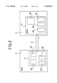
- FIG. 2 is a block diagram showing a control of the drive according to FIG. 1.
- FIG. 1 there is seen an engine 1 which is controlled by an engine control 2 and a transmission or gearbox 3 which is controlled by a gear shifting configuration 4.
- the engine control 2 and the gear shifting configuration 4 are connected through the use of a communication channel 6 which is constructed, for example, as a CAN bus.
- This bus is only schematically illustrated herein, since it is generally known and described in many publications.
- the bidirectional connection of the engine control 2 to the communication channel 6 is schematically indicated by a line 9 and the bidirectional connection of the gear shifting configuration 4 to the communication channel 6 is indicated by a line 10.
- a gear shift lever 16, a kickdown switch 17 and a driving program selection switch 18 are connected to the gear shifting configuration 4 through the use of signal lines 12, 13 and 14.
- the driver enters his or her instructions or wishes into the gear shifting configuration 4 through the use of the following control elements: settings P, R, N, D, 2 and 1 being selected through the use of the gear shift lever 16, a request for strong acceleration being selected through the use of the kickdown switch 17 and a choice between an "economy" and a "sport" driving program being selected through the use of the driving program selection switch 18.
- the engine 1 is connected to the engine control 2 through the use of control and signal lines 15. Sensor signals relating to the engine speed, the engine temperature and other known operating parameters are transmitted from the engine 1 to the engine control 2 and instructions for controlling the ignition, the fuel injection quantity, the ignition time and, if appropriate, other known engine parameters, are transferred from the engine control 2 to the engine 1.
- the engine 1 and the transmission 3 are illustrated separately herein for the sake of better clarity. However, it is generally known that a power output shaft of the engine 1 is connected directly to a torque convertor 20 of the transmission 3. Correspondingly, a power output shaft 21 is also connected to a power output train of the motor vehicle.
- the chassis, the wheel suspensions, the wheels and further components of the motor vehicle are not illustrated herein since they are not affected by the invention and are generally known.
- a transmission control which are chassis-specific or engine-specific, i.e. which depend on the data of the engine and of the chassis of the motor vehicle, are integrated in this case and are combined under reference numeral 5 into the engine control 2 as shown in FIG. 2.
- These functional units include: a shift logic or shift point selection control 22, a driver or driving characteristics classification 24, a diagnostic circuit 25 and basic modules 26 which, for example, carry out data input and output procedures.
- the shift logic 22 can be constructed as a fuzzy control and in this case can also contain the functions of driver or driving characteristics classification, route evaluation and dynamic shift point correction (see Published European Patent Application 0 622 570 A1).
- the computer-controlled gear shifting configuration 4 which is also referred to as SGCU (Smart Gear Change Unit), contains essentially only functional units which are dependent on the data of the transmission. These are a shift sequence control 28, a diagnostic circuit 29 for actuators, a control 30 of a convertor lockup clutch or TCC (Torque Convertor Clutch) and basic modules 32 which, for example, process signals of known sensors that are near to the transmission, for example signals of engine speed sensors in the transmission, of temperature sensors and of hydraulic pressure sensors in the transmission, etc..
- TCC Torque Convertor Clutch
- the gear shifting configuration 4 is constructed in such a way that only minimum chassis-dependent and engine-dependent parameterization of its functions is necessary, i.e. only a very small amount of data on the chassis and the engine of the respective motor vehicle have to be contained.
- the gear shifting configuration 4 is directly attached to the housing of the transmission 3 or accommodated in this housing. It is supplied by the manufacturer together with the transmission as one unit.
- State variables Z and control variables S are exchanged between the engine control (EC) 2 and the gear shifting configuration (SGCU) 4 through the communication channel.
- An example of the data to be exchanged is illustrated in the following table.
- CC signifies the convertor lockup clutch of the transmission.
- parameters which are necessary for controlling the gear changing process can also be exchanged between the engine control 2 and the gear shifting configuration 4 through the communication channel 6. These parameters are expediently transmitted as physical units. An example of the parameters to be transmitted is illustrated in the following table.
- shift types in this case refers to the gear changes which are acceptable depending on the respective transmission.
- down-shifting from fifth into first or second and to a certain extent also into third gear is not permitted in many transmissions.
- gear shifting configuration 4 only a minimum of engine-specific and chassis-specific data are required by the gear shifting configuration 4.
- the latter is completely independent of the data of the engine and the chassis.
- Only a minimum of transmission-specific data is required in the engine control 2.
- the result of this is that the gear shifting configuration does not have to be adapted to different varieties of engine and chassis during manufacture.
- the microprocessor or computer (which is not illustrated herein since it is generally known) contained in the gear shifting configuration ensures that adaptation is carried out through the use of transmitted engine and chassis parameters.
- Another possibility is to store data sets for the various varieties of vehicle in the gear shifting configuration 4 and to activate the respective data set of one of these varieties through the use of a code word which is transmitted to the gear shifting configuration 4 through the communication channel 6.
- identification information can also be exchanged between the engine control and the gear shifting configuration. This permits the following:
- the components are replaced, for example within the scope of repairs, there is a provision for the components to exchange identification data through the communication channel 6 which are variety-specific, i.e. which identify the type of motor vehicle for which the respective component is suitable.
- the other components or control units are capable of detecting whether or not they are capable of operating with one another. In this way it is possible to detect whether or not, for example, a transmission which is unsuitable for the motor vehicle has been inadvertently installed.
Abstract
Description
______________________________________
EC to SGCU    Type   SGCU to EC       Type
______________________________________
E.sub.eng,act (actual engine
              Z                       Z
torque)
T.sub.des (desired transmission
              S      T.sub.des, o.k. (acceptance of
                                      Z
ratio)               desired transmission
                     ratio)
                     T.sub.act (actual transmission
                                      Z
                     ratio)
CC slip.sub.des (desired CC
              S      CC slip.sub.act (actual CC slip)
                                      Z
slip)
                     Fault status of the SGCU
                                      Z
                     Malfunction of the SGCU
                                      Z
                     Restriction of functions
                                      Z
                     of the SGCU
E.sub.red,act (actual torque
              Z      E.sub.red,des (desired torque
                                      S
reduction)           reduction)
                     Gearbox temperature
                                      Z
                     Converter booster
                                      Z
                     Gear shift lever position
                                      Z
______________________________________
______________________________________
EC to SGCU          SGCU to EC
______________________________________
Mass moment of inertia
                    Number of gears
Mass of vehicle     Transmission ratios
Wheel size          Shift types
______________________________________
Claims (10)
Applications Claiming Priority (3)
| Application Number | Priority Date | Filing Date | Title |
|---|---|---|---|
| DE93113672 | 1993-08-26 | ||
| EP93113672 | 1993-08-26 | ||
| PCT/EP1994/002808 WO1995005951A1 (en) | 1993-08-26 | 1994-08-25 | Motor vehicle control |
Related Parent Applications (1)
| Application Number | Title | Priority Date | Filing Date |
|---|---|---|---|
| PCT/EP1994/002808 Continuation WO1995005951A1 (en) | 1993-08-26 | 1994-08-25 | Motor vehicle control |
Publications (1)
| Publication Number | Publication Date |
|---|---|
| US6148256A true US6148256A (en) | 2000-11-14 |
Family
ID=8213215
Family Applications (1)
| Application Number | Title | Priority Date | Filing Date |
|---|---|---|---|
| US08/605,467 Expired - Fee Related US6148256A (en) | 1993-08-26 | 1996-02-26 | Control for a motor vehicle with an automotive transmission and a smart gear change unit |
Country Status (6)
| Country | Link |
|---|---|
| US (1) | US6148256A (en) |
| EP (1) | EP0714354B1 (en) |
| JP (1) | JP3529383B2 (en) |
| KR (1) | KR960704731A (en) |
| DE (1) | DE59401427D1 (en) |
| WO (1) | WO1995005951A1 (en) |
Cited By (5)
| Publication number | Priority date | Publication date | Assignee | Title |
|---|---|---|---|---|
| KR20020058849A (en) * | 2000-12-30 | 2002-07-12 | 이계안 | A integrated development environment providing system |
| US20040078128A1 (en) * | 2000-12-27 | 2004-04-22 | Bernd Dietzel | Device for electronically controlling a gearbox, particularly an automatic gearbox |
| US20110251735A1 (en) * | 2010-04-07 | 2011-10-13 | Takao Hayashi | Traveling Vehicle System and Self-Diagnosis Method for the Traveling Vehicle System |
| CN104343957A (en) * | 2014-09-15 | 2015-02-11 | 山东理工大学 | Method for controlling rising and falling process of multi-gear wire-controlled automatic speed changer |
| US20150276052A1 (en) * | 2014-03-27 | 2015-10-01 | GM Global Technology Operations LLC | Transmission with commanded gear shift monitoring logic |
Families Citing this family (8)
| Publication number | Priority date | Publication date | Assignee | Title |
|---|---|---|---|---|
| WO1995034437A1 (en) * | 1994-06-10 | 1995-12-21 | Siemens Aktiengesellschaft | Control unit for a motor vehicle |
| IT1266914B1 (en) * | 1994-08-05 | 1997-01-21 | Magneti Marelli Spa | POWER-ASSISTED GEARBOX CONTROL SYSTEM. |
| JPH08296492A (en) * | 1995-04-27 | 1996-11-12 | Jatco Corp | Electronic control device for automobile |
| DE19945352A1 (en) * | 1999-09-22 | 2001-04-19 | Voith Turbo Kg | Device for controlling a gear unit |
| DE10014218A1 (en) * | 2000-03-22 | 2001-10-04 | Bosch Gmbh Robert | Automobile automatic gearbox control method controls gearbox dependent on direct fuel injection IC engine operating mode |
| DE10127308A1 (en) * | 2001-06-06 | 2002-12-12 | Wittenstein Ag | Electric motor drive system for use in road vehicle has status sensors that are coupled to external status monitoring system and includes torque, temperature and electric current sensors |
| KR100678832B1 (en) * | 2002-12-10 | 2007-02-05 | 현대중공업 주식회사 | 2 Stage Engine Power depend on transmission gear stage in wheel loader and method |
| CN103213544B (en) * | 2012-01-20 | 2015-05-13 | 厦门金龙联合汽车工业有限公司 | Determination system and method of economic driving gear of engine driven vehicle |
Citations (21)
| Publication number | Priority date | Publication date | Assignee | Title |
|---|---|---|---|---|
| US4703428A (en) * | 1983-12-14 | 1987-10-27 | Nissan Motor Co., Ltd. | Power train control method on common input data |
| US4945481A (en) * | 1986-05-08 | 1990-07-31 | Toyota Jidosha Kabushiki Kaisha | System for integrally controlling automatic transmission and engine |
| EP0425199A2 (en) * | 1989-10-27 | 1991-05-02 | Hitachi, Ltd. | Motor vehicle control system and control unit thereof |
| US5012695A (en) * | 1988-10-07 | 1991-05-07 | Mazda Motor Corporation | Gear-shifting shock suppressing system for automatic transmission vehicle |
| DE4021251A1 (en) * | 1989-12-04 | 1991-06-06 | Mitsubishi Electric Corp | Multiprocessor system with high speed data exchange - has address generator combining offset register values with bus address values, requires no data communications software |
| US5091856A (en) * | 1989-04-14 | 1992-02-25 | Hitachi, Ltd. | Control apparatus for automobiles |
| EP0532363A2 (en) * | 1991-09-12 | 1993-03-17 | Honda Giken Kogyo Kabushiki Kaisha | Vehicle automatic transmission control system |
| US5228368A (en) * | 1990-11-19 | 1993-07-20 | Nissan Motor Co., Ltd. | Control system for supercharged engine/automatic transmission combination |
| EP0554465A1 (en) * | 1991-09-03 | 1993-08-11 | Nippondenso Co., Ltd. | Control module assembly unit for mounting on vehicle |
| US5307270A (en) * | 1990-03-06 | 1994-04-26 | Siemens Aktiengesellschaft | Control system for a motor vehicle drive |
| US5323667A (en) * | 1992-10-02 | 1994-06-28 | Caterpillar Inc. | Integrated engine and transmission control system |
| US5335568A (en) * | 1991-08-30 | 1994-08-09 | Siemens Aktiengesellschaft | Control for a motor vehicle drive having an automatic transmission |
| EP0622570A1 (en) * | 1993-04-27 | 1994-11-02 | Siemens Aktiengesellschaft | Control system for vehicle automatic transmission |
| US5369584A (en) * | 1989-12-08 | 1994-11-29 | Mitsubishi Denki Kabushiki Kaisha | Control apparatus for a vehicle |
| US5369581A (en) * | 1989-03-17 | 1994-11-29 | Hitachi, Ltd. | Vehicle control apparatus and method therefor |
| EP0388107B1 (en) * | 1989-03-17 | 1994-11-30 | Hitachi, Ltd. | Vehicle control apparatus and method therefor |
| US5390117A (en) * | 1992-06-30 | 1995-02-14 | Siemens Aktiengesellschaft | Transmission control with a fuzzy logic controller |
| US5396420A (en) * | 1991-05-17 | 1995-03-07 | Siemens Aktiengesellschaft | Control unit for automatic transmissions in motor vehicles |
| US5436834A (en) * | 1990-08-14 | 1995-07-25 | Siemens Aktiengesellschaft | Transmission control for a motor vehicle with adaptation of shift points to driving habits of a driver |
| US5547434A (en) * | 1991-08-22 | 1996-08-20 | Siemens Aktiengesellschaft | Control for a motor vehicle drive having an automatic transmission |
| US6026342A (en) * | 1994-06-10 | 2000-02-15 | Siemens Aktiengesellschaft | Control unit for a motor vehicle |
-
1994
- 1994-08-25 JP JP50735195A patent/JP3529383B2/en not_active Expired - Fee Related
- 1994-08-25 KR KR1019960700939A patent/KR960704731A/en not_active Application Discontinuation
- 1994-08-25 WO PCT/EP1994/002808 patent/WO1995005951A1/en active IP Right Grant
- 1994-08-25 DE DE59401427T patent/DE59401427D1/en not_active Expired - Lifetime
- 1994-08-25 EP EP94925474A patent/EP0714354B1/en not_active Expired - Lifetime
-
1996
- 1996-02-26 US US08/605,467 patent/US6148256A/en not_active Expired - Fee Related
Patent Citations (21)
| Publication number | Priority date | Publication date | Assignee | Title |
|---|---|---|---|---|
| US4703428A (en) * | 1983-12-14 | 1987-10-27 | Nissan Motor Co., Ltd. | Power train control method on common input data |
| US4945481A (en) * | 1986-05-08 | 1990-07-31 | Toyota Jidosha Kabushiki Kaisha | System for integrally controlling automatic transmission and engine |
| US5012695A (en) * | 1988-10-07 | 1991-05-07 | Mazda Motor Corporation | Gear-shifting shock suppressing system for automatic transmission vehicle |
| EP0388107B1 (en) * | 1989-03-17 | 1994-11-30 | Hitachi, Ltd. | Vehicle control apparatus and method therefor |
| US5369581A (en) * | 1989-03-17 | 1994-11-29 | Hitachi, Ltd. | Vehicle control apparatus and method therefor |
| US5091856A (en) * | 1989-04-14 | 1992-02-25 | Hitachi, Ltd. | Control apparatus for automobiles |
| EP0425199A2 (en) * | 1989-10-27 | 1991-05-02 | Hitachi, Ltd. | Motor vehicle control system and control unit thereof |
| DE4021251A1 (en) * | 1989-12-04 | 1991-06-06 | Mitsubishi Electric Corp | Multiprocessor system with high speed data exchange - has address generator combining offset register values with bus address values, requires no data communications software |
| US5369584A (en) * | 1989-12-08 | 1994-11-29 | Mitsubishi Denki Kabushiki Kaisha | Control apparatus for a vehicle |
| US5307270A (en) * | 1990-03-06 | 1994-04-26 | Siemens Aktiengesellschaft | Control system for a motor vehicle drive |
| US5436834A (en) * | 1990-08-14 | 1995-07-25 | Siemens Aktiengesellschaft | Transmission control for a motor vehicle with adaptation of shift points to driving habits of a driver |
| US5228368A (en) * | 1990-11-19 | 1993-07-20 | Nissan Motor Co., Ltd. | Control system for supercharged engine/automatic transmission combination |
| US5396420A (en) * | 1991-05-17 | 1995-03-07 | Siemens Aktiengesellschaft | Control unit for automatic transmissions in motor vehicles |
| US5547434A (en) * | 1991-08-22 | 1996-08-20 | Siemens Aktiengesellschaft | Control for a motor vehicle drive having an automatic transmission |
| US5335568A (en) * | 1991-08-30 | 1994-08-09 | Siemens Aktiengesellschaft | Control for a motor vehicle drive having an automatic transmission |
| EP0554465A1 (en) * | 1991-09-03 | 1993-08-11 | Nippondenso Co., Ltd. | Control module assembly unit for mounting on vehicle |
| EP0532363A2 (en) * | 1991-09-12 | 1993-03-17 | Honda Giken Kogyo Kabushiki Kaisha | Vehicle automatic transmission control system |
| US5390117A (en) * | 1992-06-30 | 1995-02-14 | Siemens Aktiengesellschaft | Transmission control with a fuzzy logic controller |
| US5323667A (en) * | 1992-10-02 | 1994-06-28 | Caterpillar Inc. | Integrated engine and transmission control system |
| EP0622570A1 (en) * | 1993-04-27 | 1994-11-02 | Siemens Aktiengesellschaft | Control system for vehicle automatic transmission |
| US6026342A (en) * | 1994-06-10 | 2000-02-15 | Siemens Aktiengesellschaft | Control unit for a motor vehicle |
Cited By (8)
| Publication number | Priority date | Publication date | Assignee | Title |
|---|---|---|---|---|
| US20040078128A1 (en) * | 2000-12-27 | 2004-04-22 | Bernd Dietzel | Device for electronically controlling a gearbox, particularly an automatic gearbox |
| KR20020058849A (en) * | 2000-12-30 | 2002-07-12 | 이계안 | A integrated development environment providing system |
| US20110251735A1 (en) * | 2010-04-07 | 2011-10-13 | Takao Hayashi | Traveling Vehicle System and Self-Diagnosis Method for the Traveling Vehicle System |
| US8712600B2 (en) * | 2010-04-07 | 2014-04-29 | Murata Machinery Ltd. | Traveling vehicle system and self-diagnosis method for the traveling vehicle system |
| US20150276052A1 (en) * | 2014-03-27 | 2015-10-01 | GM Global Technology Operations LLC | Transmission with commanded gear shift monitoring logic |
| US9200704B2 (en) * | 2014-03-27 | 2015-12-01 | GM Global Technology Operations LLC | Transmission with commanded gear shift monitoring logic |
| CN104343957A (en) * | 2014-09-15 | 2015-02-11 | 山东理工大学 | Method for controlling rising and falling process of multi-gear wire-controlled automatic speed changer |
| CN104343957B (en) * | 2014-09-15 | 2016-08-24 | 山东理工大学 | The upshift course control method for use keeping off line traffic control automatic transmission more |
Also Published As
| Publication number | Publication date |
|---|---|
| EP0714354A1 (en) | 1996-06-05 |
| JPH09502676A (en) | 1997-03-18 |
| KR960704731A (en) | 1996-10-09 |
| JP3529383B2 (en) | 2004-05-24 |
| EP0714354B1 (en) | 1996-12-27 |
| DE59401427D1 (en) | 1997-02-06 |
| WO1995005951A1 (en) | 1995-03-02 |
Similar Documents
| Publication | Publication Date | Title |
|---|---|---|
| US5676620A (en) | Control system for a motor vehicle | |
| EP1617106B1 (en) | Common control interface for diverse automated manual transmissions | |
| US5749060A (en) | Automatic transmission control for a motor vehicle | |
| US5655408A (en) | Failure detecting system and method for automatic transmission | |
| US6148256A (en) | Control for a motor vehicle with an automotive transmission and a smart gear change unit | |
| US5396420A (en) | Control unit for automatic transmissions in motor vehicles | |
| US5035158A (en) | Electric shift and transfer case apparatus with control system therefore | |
| US6199003B1 (en) | Apparatus and method for manually shifting an automatic transmission | |
| US6026342A (en) | Control unit for a motor vehicle | |
| US6067492A (en) | Display system for automatic transmissions | |
| US5203235A (en) | Control system for automotive automatic transmission | |
| US5341703A (en) | Performance mode and economy mode shift scheduling in an automatic transmission | |
| US4891759A (en) | Control system for automotive automatic transmission including downshift select shock suppression arrangement | |
| EP0467233B1 (en) | Automatic transmission | |
| EP0431538A2 (en) | Manual override for automated mechanical transmission | |
| US5417627A (en) | Shift controller using shift timing or speed ratio dependent on the change of one way clutch for automotive automatic transmission | |
| US5081583A (en) | Automatic control system for gear transmission | |
| Nordgård et al. | Developments in automated clutch management systems | |
| US5669848A (en) | Control system for automatic transmission for vehicle | |
| US5505670A (en) | Automatic transmission | |
| WO2002092376A1 (en) | Apparatus for converting a manual transmission of an automobile into an automated manual transmission | |
| US6106433A (en) | Control system of automotive automatic transmission | |
| JPS6256655A (en) | Speed change controller for speed change gear | |
| KR100289485B1 (en) | Method for shift pattern controlling of auto tramsmission | |
| JPH0446262A (en) | Shift control device for automatic transmission |
Legal Events
| Date | Code | Title | Description |
|---|---|---|---|
| AS | Assignment |
Owner name: SIEMENS AKTIENGESELLSCHAFT, GERMANY Free format text: ASSIGNMENT OF ASSIGNORS INTEREST;ASSIGNORS:GRAF, FRIEDRICH;SCHAFER, JOACHIM;STORJOHANN, KAI;AND OTHERS;REEL/FRAME:011090/0364;SIGNING DATES FROM 19940208 TO 19940816 |
|
| FEPP | Fee payment procedure |
Free format text: PAYOR NUMBER ASSIGNED (ORIGINAL EVENT CODE: ASPN); ENTITY STATUS OF PATENT OWNER: LARGE ENTITY |
|
| FPAY | Fee payment |
Year of fee payment: 4 |
|
| FEPP | Fee payment procedure |
Free format text: PAYER NUMBER DE-ASSIGNED (ORIGINAL EVENT CODE: RMPN); ENTITY STATUS OF PATENT OWNER: LARGE ENTITY Free format text: PAYOR NUMBER ASSIGNED (ORIGINAL EVENT CODE: ASPN); ENTITY STATUS OF PATENT OWNER: LARGE ENTITY |
|
| FPAY | Fee payment |
Year of fee payment: 8 |
|
| REMI | Maintenance fee reminder mailed | ||
| LAPS | Lapse for failure to pay maintenance fees | ||
| STCH | Information on status: patent discontinuation |
Free format text: PATENT EXPIRED DUE TO NONPAYMENT OF MAINTENANCE FEES UNDER 37 CFR 1.362 |
|
| FP | Lapsed due to failure to pay maintenance fee |
Effective date: 20121114 |