US6148628A - Electronic expansion valve without pressure sensor reading - Google Patents
Electronic expansion valve without pressure sensor reading Download PDFInfo
- Publication number
- US6148628A US6148628A US09/277,333 US27733399A US6148628A US 6148628 A US6148628 A US 6148628A US 27733399 A US27733399 A US 27733399A US 6148628 A US6148628 A US 6148628A
- Authority
- US
- United States
- Prior art keywords
- refrigeration system
- approximate
- evaporator
- superheat level
- expansion valve
- Prior art date
- Legal status (The legal status is an assumption and is not a legal conclusion. Google has not performed a legal analysis and makes no representation as to the accuracy of the status listed.)
- Expired - Lifetime
Links
- 238000005057 refrigeration Methods 0.000 claims abstract description 28
- 238000000034 method Methods 0.000 claims abstract description 14
- 238000012544 monitoring process Methods 0.000 claims abstract description 9
- 230000004044 response Effects 0.000 claims 2
- 239000003507 refrigerant Substances 0.000 description 25
- 239000003570 air Substances 0.000 description 16
- 239000007788 liquid Substances 0.000 description 5
- 229920006395 saturated elastomer Polymers 0.000 description 4
- 230000008901 benefit Effects 0.000 description 3
- 239000002826 coolant Substances 0.000 description 3
- 239000012080 ambient air Substances 0.000 description 2
- 238000006073 displacement reaction Methods 0.000 description 2
- 238000012986 modification Methods 0.000 description 2
- 230000004048 modification Effects 0.000 description 2
- 239000010705 motor oil Substances 0.000 description 2
- 230000001360 synchronised effect Effects 0.000 description 2
- 238000007792 addition Methods 0.000 description 1
- 238000004364 calculation method Methods 0.000 description 1
- 238000013461 design Methods 0.000 description 1
- 230000000694 effects Effects 0.000 description 1
- 230000005669 field effect Effects 0.000 description 1
- 230000006870 function Effects 0.000 description 1
- 238000005259 measurement Methods 0.000 description 1
- 230000002093 peripheral effect Effects 0.000 description 1
- 238000012360 testing method Methods 0.000 description 1
Images

Classifications
-
- B—PERFORMING OPERATIONS; TRANSPORTING
- B60—VEHICLES IN GENERAL
- B60H—ARRANGEMENTS OF HEATING, COOLING, VENTILATING OR OTHER AIR-TREATING DEVICES SPECIALLY ADAPTED FOR PASSENGER OR GOODS SPACES OF VEHICLES
- B60H1/00—Heating, cooling or ventilating [HVAC] devices
- B60H1/32—Cooling devices
- B60H1/3204—Cooling devices using compression
- B60H1/3205—Control means therefor
- B60H1/3211—Control means therefor for increasing the efficiency of a vehicle refrigeration cycle
-
- B—PERFORMING OPERATIONS; TRANSPORTING
- B60—VEHICLES IN GENERAL
- B60H—ARRANGEMENTS OF HEATING, COOLING, VENTILATING OR OTHER AIR-TREATING DEVICES SPECIALLY ADAPTED FOR PASSENGER OR GOODS SPACES OF VEHICLES
- B60H1/00—Heating, cooling or ventilating [HVAC] devices
- B60H1/32—Cooling devices
- B60H1/3204—Cooling devices using compression
- B60H1/3205—Control means therefor
- B60H1/3219—Control means therefor for improving the response time of a vehicle refrigeration cycle
-
- F—MECHANICAL ENGINEERING; LIGHTING; HEATING; WEAPONS; BLASTING
- F25—REFRIGERATION OR COOLING; COMBINED HEATING AND REFRIGERATION SYSTEMS; HEAT PUMP SYSTEMS; MANUFACTURE OR STORAGE OF ICE; LIQUEFACTION SOLIDIFICATION OF GASES
- F25B—REFRIGERATION MACHINES, PLANTS OR SYSTEMS; COMBINED HEATING AND REFRIGERATION SYSTEMS; HEAT PUMP SYSTEMS
- F25B41/00—Fluid-circulation arrangements
- F25B41/30—Expansion means; Dispositions thereof
- F25B41/31—Expansion valves
- F25B41/34—Expansion valves with the valve member being actuated by electric means, e.g. by piezoelectric actuators
-
- B—PERFORMING OPERATIONS; TRANSPORTING
- B60—VEHICLES IN GENERAL
- B60H—ARRANGEMENTS OF HEATING, COOLING, VENTILATING OR OTHER AIR-TREATING DEVICES SPECIALLY ADAPTED FOR PASSENGER OR GOODS SPACES OF VEHICLES
- B60H1/00—Heating, cooling or ventilating [HVAC] devices
- B60H1/32—Cooling devices
- B60H2001/3236—Cooling devices information from a variable is obtained
- B60H2001/3248—Cooling devices information from a variable is obtained related to pressure
- B60H2001/325—Cooling devices information from a variable is obtained related to pressure of the refrigerant at a compressing unit
-
- B—PERFORMING OPERATIONS; TRANSPORTING
- B60—VEHICLES IN GENERAL
- B60H—ARRANGEMENTS OF HEATING, COOLING, VENTILATING OR OTHER AIR-TREATING DEVICES SPECIALLY ADAPTED FOR PASSENGER OR GOODS SPACES OF VEHICLES
- B60H1/00—Heating, cooling or ventilating [HVAC] devices
- B60H1/32—Cooling devices
- B60H2001/3236—Cooling devices information from a variable is obtained
- B60H2001/3248—Cooling devices information from a variable is obtained related to pressure
- B60H2001/3252—Cooling devices information from a variable is obtained related to pressure of the refrigerant at an evaporating unit
-
- B—PERFORMING OPERATIONS; TRANSPORTING
- B60—VEHICLES IN GENERAL
- B60H—ARRANGEMENTS OF HEATING, COOLING, VENTILATING OR OTHER AIR-TREATING DEVICES SPECIALLY ADAPTED FOR PASSENGER OR GOODS SPACES OF VEHICLES
- B60H1/00—Heating, cooling or ventilating [HVAC] devices
- B60H1/32—Cooling devices
- B60H2001/3236—Cooling devices information from a variable is obtained
- B60H2001/3255—Cooling devices information from a variable is obtained related to temperature
- B60H2001/3257—Cooling devices information from a variable is obtained related to temperature of the refrigerant at a compressing unit
-
- B—PERFORMING OPERATIONS; TRANSPORTING
- B60—VEHICLES IN GENERAL
- B60H—ARRANGEMENTS OF HEATING, COOLING, VENTILATING OR OTHER AIR-TREATING DEVICES SPECIALLY ADAPTED FOR PASSENGER OR GOODS SPACES OF VEHICLES
- B60H1/00—Heating, cooling or ventilating [HVAC] devices
- B60H1/32—Cooling devices
- B60H2001/3236—Cooling devices information from a variable is obtained
- B60H2001/3255—Cooling devices information from a variable is obtained related to temperature
- B60H2001/3258—Cooling devices information from a variable is obtained related to temperature of the air at a condensing unit
-
- B—PERFORMING OPERATIONS; TRANSPORTING
- B60—VEHICLES IN GENERAL
- B60H—ARRANGEMENTS OF HEATING, COOLING, VENTILATING OR OTHER AIR-TREATING DEVICES SPECIALLY ADAPTED FOR PASSENGER OR GOODS SPACES OF VEHICLES
- B60H1/00—Heating, cooling or ventilating [HVAC] devices
- B60H1/32—Cooling devices
- B60H2001/3236—Cooling devices information from a variable is obtained
- B60H2001/3255—Cooling devices information from a variable is obtained related to temperature
- B60H2001/3261—Cooling devices information from a variable is obtained related to temperature of the air at an evaporating unit
-
- B—PERFORMING OPERATIONS; TRANSPORTING
- B60—VEHICLES IN GENERAL
- B60H—ARRANGEMENTS OF HEATING, COOLING, VENTILATING OR OTHER AIR-TREATING DEVICES SPECIALLY ADAPTED FOR PASSENGER OR GOODS SPACES OF VEHICLES
- B60H1/00—Heating, cooling or ventilating [HVAC] devices
- B60H1/32—Cooling devices
- B60H2001/3236—Cooling devices information from a variable is obtained
- B60H2001/3266—Cooling devices information from a variable is obtained related to the operation of the vehicle
-
- B—PERFORMING OPERATIONS; TRANSPORTING
- B60—VEHICLES IN GENERAL
- B60H—ARRANGEMENTS OF HEATING, COOLING, VENTILATING OR OTHER AIR-TREATING DEVICES SPECIALLY ADAPTED FOR PASSENGER OR GOODS SPACES OF VEHICLES
- B60H1/00—Heating, cooling or ventilating [HVAC] devices
- B60H1/32—Cooling devices
- B60H2001/3269—Cooling devices output of a control signal
- B60H2001/3285—Cooling devices output of a control signal related to an expansion unit
-
- Y—GENERAL TAGGING OF NEW TECHNOLOGICAL DEVELOPMENTS; GENERAL TAGGING OF CROSS-SECTIONAL TECHNOLOGIES SPANNING OVER SEVERAL SECTIONS OF THE IPC; TECHNICAL SUBJECTS COVERED BY FORMER USPC CROSS-REFERENCE ART COLLECTIONS [XRACs] AND DIGESTS
- Y02—TECHNOLOGIES OR APPLICATIONS FOR MITIGATION OR ADAPTATION AGAINST CLIMATE CHANGE
- Y02B—CLIMATE CHANGE MITIGATION TECHNOLOGIES RELATED TO BUILDINGS, e.g. HOUSING, HOUSE APPLIANCES OR RELATED END-USER APPLICATIONS
- Y02B30/00—Energy efficient heating, ventilation or air conditioning [HVAC]
- Y02B30/70—Efficient control or regulation technologies, e.g. for control of refrigerant flow, motor or heating
Definitions
- the field of the present invention relates to control systems for transport refrigeration systems. More specifically, the present invention is directed towards enabling the actuation of an electronic expansion valve in a transport refrigeration system without the benefit of an evaporator refrigerant outlet pressure reading or measurement.
- a transport refrigeration system used to control enclosed areas functions by absorbing heat from the enclosed area and releasing heat outside of the box into the environment.
- a typical transport refrigeration unit requires a highly pressurized refrigerant is introduced into a low pressure environment such as an evaporator coil.
- the refrigerant absorbs heat from the box return air across the evaporator coil and boils and evaporates.
- This refrigerant vapor is removed from the evaporator, and is compressed to a higher temperature and higher pressure through the use of a compressor, and is then turned back into liquid refrigerant by passing through a condenser.
- the flow of refrigerant through the evaporator coil is typically controlled by a valve, such as an electronic expansion valve or EXV.
- a valve such as an electronic expansion valve or EXV.
- Refrigeration systems requires operation under a wide variety of ambient temperatures and operating loads.
- the applicants have found that, in order to operate properly under low box temperature conditions, it was desirable to use particular commercially available pressure transducers for sensing the evaporator refrigerant in order to obtain high accuracy in reading the evaporator outlet pressure under low box temperature conditions.
- this transducer does not result in accurate readings outside a refrigerant pressure range of -14.7 psig to about 100 psig.
- the present invention discloses a system and process for controlling an electronic exchange valve for an transport refrigeration system evaporator in the absence of a evaporator outlet pressure transducer reading.
- the process includes monitoring for the absence of reliable evaporator outlet pressure readings, monitoring the supply air temperature, and supplying the supply air temperature to a processor within a controller for use in an algorithm so as to approximate the saturation reference temperature and superheat levels to derive the necessary control signals for the EXV.
- one object of the present invention is to provide a microprocessor control for the calculation of superheat levels to control an EXV.
- FIG. 1 shows a schematic of the transport refrigeration system of the present invention
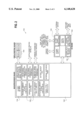
- FIG. 2 shows a block schematic of a first preferred embodiment of a controller of the present invention.
- FIG. 2a shows a block schematic of a second preferred embodiment of a controller of the present invention.
- the invention that is the subject of the present application is one of a series of applications dealing with transport refrigeration system design and control, the other copending applications including: “Voltage Control Using Engine Speed” (U.S. patent application Ser. No. 09/277,507); “Economy Mode For Transport Refrigeration Units” (U.S. Pat. No. 6,044,651); “Compressor Operating Envelope Management” (U.S. patent application Ser. No. 09/277,473); “High Engine Coolant Temperature Control” (U.S. patent application Ser. No. 09/277,472); “Generator Power Management” (U.S. patent application Ser. No. 09/277,509); and “Electronic Expansion Valve Control Without Pressure Sensor Reading” (U.S.
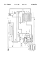
- FIG. 1 illustrates a schematic representation of the transport refrigeration system 100 of the present invention.
- the refrigerant (which, in its most preferred embodiment is R404A) is used to cool the box air (i.e., the air within the container or trailer or truck) of the refrigeration transport system 100.
- motor 118 to be a diesel engine, most preferably a four cylinder, 2200 cc displacement diesel engine which preferably operates at a high speed (about 1950 RPM) or at low speed (about 1350 RPM).
- the motor or engine 118 most preferably drives a 6 cylinder compressor 116 having a displacement of 600 cc, the compressor 116 further having two unloaders, each for selectively unloading a pair of cylinders under selective operating conditions.
- the (preferably vapor state) refrigerant is compressed to a higher temperature and pressure.
- the refrigerant then moves to the air-cooled condenser 114, which includes a plurality of condenser coil fins and tubes 122, which receive air, typically blown by a condenser fan (not shown).
- the refrigerant condenses to a high pressure/high temperature liquid and flow to a receiver 132 that provides storage for excess liquid refrigerant during low temperature operation.
- the refrigerant flows through subcooler unit 140, then to a filter-drier 124 which keeps the refrigerant clean and dry, and then to a heat exchanger 142, which increases the refrigerant subcooling.
- the refrigerant flows to an electronic expansion valve 144 (the "EXV").
- EXV electronic expansion valve
- the refrigerant then flows through the tubes or coils 126 of the evaporator 112, which absorbs heat from the return air (i.e., air returning from the box) and in so doing, vaporizes the remaining liquid refrigerant.
- the return air is preferably drawn or pushed across the tubes or coils 126 by at least one evaporator fan (not shown).
- the refrigerant vapor is then drawn from the exhanger 112 through a suction modulation valve (or "SMV”) back into the compressor.
- SMV suction modulation valve
- Controller 150 preferably includes a microprocessor 154 and its associated memory 156.
- the memory 156 of controller 150 can contain operator or owner preselected, desired values for various operating parameters within the system, including, but not limited to temperature set point for various locations within the system 100 or the box, pressure limits, current limits, engine speed limits, and any variety of other desired operating parameters or limits with the system 100.
- Controller 150 most preferably includes a microprocessor board 160 that contains microprocessor 154 and memory 156, an input/output (I/O) board 162, which contains an analog to digital converter 156 which receives temperature inputs and pressure inputs from various points in the system, AC current inputs, DC current inputs, voltage inputs and humidity level inputs.
- I/O board 162 includes drive circuits or field effect transistors ("FETs") and relays which receive signals or current from the controller 150 and in turn control various external or peripheral devices in the system 100, such as SMV 130, EXV 144 and the speed of engine 118 through a solenoid (not shown).
- FETs field effect transistors
- controller 150 includes: the return air temperature (RAT) sensor which inputs into the processor 154 a variable resistor value according to the evaporator return air temperature; the ambient air temperature (AAT) which inputs into microprocessor 154 a variable resistor value according to the ambient air temperature read in front of the condenser 114; the compressor suction temperature (CST) sensor; which inputs to the microprocessor a variable resistor value according to the compressor suction temperature; the compressor discharge temperature (CDT) sensor, which inputs to microprocessor 154 a resistor value according to the compressor discharge temperature inside the cylinder head of compressor 116; the evaporator outlet temperature (EVOT) sensor, which inputs to microprocessor 154 a variable resistor value according to the outlet temperature of evaporator 112; the generator temperature (GENT) sensor, which inputs to microprocessor 154 a resistor value according to the generator temperature; the engine coolant temperature (ENCT) sensor, which inputs to microprocessor 154
- EXV such as EXV 144 is controlled by controller 150, which uses control logic to calculate the desired EXV position based upon the difference between a desired evaporator outlet refrigerant superheat (typically stored, such as in memory 156) and the actual evaporator outlet superheat.
- a desired evaporator outlet refrigerant superheat typically stored, such as in memory 156
- the refrigerant saturated temperature at the control point is need. Normally, such information is calculated from the EVOP. If, due to conditions such as those described above, such a reading is not available, the refrigerant saturated temperature can be estimated from the evaporator outlet air temperature (i.e., the air being supplied to the box of system 100) using the following equation:
- this control process is actuated whenever the EVOP value is above 99 psig for a predetermined period of time (e.g., 20 seconds) and compressor 116 has been on for some time (e.g., 5 minutes or more).
- this control process when engaged, should preferably be in effect (i.e., monitoring return air and calculating reference saturated temperatures) for a minimum period of time (e.g., 2 minutes).
- the desired superheat setting should be gradually ramped up or down to its desired level over a period of time (e.g., at least 60 seconds).
Abstract
An system and process for controlling an electronic exchange valve for an transport refrigeration system evaporator in the absence of a evaporator outlet pressure transducer reading is disclosed. The process includes monitoring for the absence of reliable evaporator outlet pressure readings, monitoring the supply air temperature, and supplying the supply air temperature to a processor within a controller for use in an algorithm so as to approximate the saturation reference temperature and superheat levels to derive the necessary control signals for the EXV.
Description
The field of the present invention relates to control systems for transport refrigeration systems. More specifically, the present invention is directed towards enabling the actuation of an electronic expansion valve in a transport refrigeration system without the benefit of an evaporator refrigerant outlet pressure reading or measurement.
A transport refrigeration system used to control enclosed areas, such as the box used on trucks, trailers, containers, or similar intermodal units, functions by absorbing heat from the enclosed area and releasing heat outside of the box into the environment. To accomplish this, a typical transport refrigeration unit requires a highly pressurized refrigerant is introduced into a low pressure environment such as an evaporator coil. The refrigerant absorbs heat from the box return air across the evaporator coil and boils and evaporates. This refrigerant vapor is removed from the evaporator, and is compressed to a higher temperature and higher pressure through the use of a compressor, and is then turned back into liquid refrigerant by passing through a condenser.
The flow of refrigerant through the evaporator coil is typically controlled by a valve, such as an electronic expansion valve or EXV.
Refrigeration systems, including particularly refrigeration transport systems, requires operation under a wide variety of ambient temperatures and operating loads. The applicants have found that, in order to operate properly under low box temperature conditions, it was desirable to use particular commercially available pressure transducers for sensing the evaporator refrigerant in order to obtain high accuracy in reading the evaporator outlet pressure under low box temperature conditions. Unfortunately, this transducer does not result in accurate readings outside a refrigerant pressure range of -14.7 psig to about 100 psig.
Therefore, the present invention discloses a system and process for controlling an electronic exchange valve for an transport refrigeration system evaporator in the absence of a evaporator outlet pressure transducer reading. The process includes monitoring for the absence of reliable evaporator outlet pressure readings, monitoring the supply air temperature, and supplying the supply air temperature to a processor within a controller for use in an algorithm so as to approximate the saturation reference temperature and superheat levels to derive the necessary control signals for the EXV.
Accordingly, one object of the present invention is to provide a microprocessor control for the calculation of superheat levels to control an EXV.
It is a further object of the invention to provide a microprocessor control for approximating superheat levels in the absence of a reliable evaporator outlet pressure reading.
It is another object of the present invention to provide a process for utilizing box supply air temperature to calculate actual superheat levels for an evaporator so as to control an EXV.
These and other objects, features, and advantages of the present invention will become more apparent in light of the following detailed description of a best mode embodiment thereof, and as illustrated in the accompanying drawings.
FIG. 1 shows a schematic of the transport refrigeration system of the present invention;
FIG. 2 shows a block schematic of a first preferred embodiment of a controller of the present invention; and
FIG. 2a shows a block schematic of a second preferred embodiment of a controller of the present invention.
The invention that is the subject of the present application is one of a series of applications dealing with transport refrigeration system design and control, the other copending applications including: "Voltage Control Using Engine Speed" (U.S. patent application Ser. No. 09/277,507); "Economy Mode For Transport Refrigeration Units" (U.S. Pat. No. 6,044,651); "Compressor Operating Envelope Management" (U.S. patent application Ser. No. 09/277,473); "High Engine Coolant Temperature Control" (U.S. patent application Ser. No. 09/277,472); "Generator Power Management" (U.S. patent application Ser. No. 09/277,509); and "Electronic Expansion Valve Control Without Pressure Sensor Reading" (U.S. patent application Ser. No. 09/277,333) all of which are assigned to the assignees of the present invention and which are hereby incorporated herein by reference. These inventions are most preferably designed for use in transportation refrigeration systems of the type described in copending applications entitled: "Transport Refrigeration Unit With Non-Synchronous Generator Power System;" Electrically Powered Trailer Refrigeration Unit With Integrally Mounted Diesel Driven Permanent Magnet Generator;" and "Transport Refrigeration Unit With Synchronous Generator Power System," each of which were invented by Robert Chopko, Kenneth Barrett, and James Wilson, and each of which were likewise assigned to the assignees of the present invention. The teachings and disclosures of these applications are likewise incorporated herein by reference.
FIG. 1 illustrates a schematic representation of the transport refrigeration system 100 of the present invention. The refrigerant (which, in its most preferred embodiment is R404A) is used to cool the box air (i.e., the air within the container or trailer or truck) of the refrigeration transport system 100. is first compressed by a compressor 116, which is driven by a motor 118, which is most preferably an integrated electric drive motor driven by a synchronous generator (not shown) operating at low speed (most preferably 45 Hz) or high speed (most preferably 65 Hz). Another preferred embodiment of the present invention, however, provides for motor 118 to be a diesel engine, most preferably a four cylinder, 2200 cc displacement diesel engine which preferably operates at a high speed (about 1950 RPM) or at low speed (about 1350 RPM). The motor or engine 118 most preferably drives a 6 cylinder compressor 116 having a displacement of 600 cc, the compressor 116 further having two unloaders, each for selectively unloading a pair of cylinders under selective operating conditions.
In the compressor 116, the (preferably vapor state) refrigerant is compressed to a higher temperature and pressure. The refrigerant then moves to the air-cooled condenser 114, which includes a plurality of condenser coil fins and tubes 122, which receive air, typically blown by a condenser fan (not shown). By removing latent heat through this step, the refrigerant condenses to a high pressure/high temperature liquid and flow to a receiver 132 that provides storage for excess liquid refrigerant during low temperature operation. From the receiver 132, the refrigerant flows through subcooler unit 140, then to a filter-drier 124 which keeps the refrigerant clean and dry, and then to a heat exchanger 142, which increases the refrigerant subcooling.
Finally, the refrigerant flows to an electronic expansion valve 144 (the "EXV"). As the liquid refrigerant passes through the orifice of the EXV, at least some of it vaporizes. The refrigerant then flows through the tubes or coils 126 of the evaporator 112, which absorbs heat from the return air (i.e., air returning from the box) and in so doing, vaporizes the remaining liquid refrigerant. The return air is preferably drawn or pushed across the tubes or coils 126 by at least one evaporator fan (not shown). The refrigerant vapor is then drawn from the exhanger 112 through a suction modulation valve (or "SMV") back into the compressor.
Many of the points in the transport refrigeration system are monitored and controlled by a controller 150. As shown in FIGS. 2 and 2A Controller 150 preferably includes a microprocessor 154 and its associated memory 156. The memory 156 of controller 150 can contain operator or owner preselected, desired values for various operating parameters within the system, including, but not limited to temperature set point for various locations within the system 100 or the box, pressure limits, current limits, engine speed limits, and any variety of other desired operating parameters or limits with the system 100. Controller 150 most preferably includes a microprocessor board 160 that contains microprocessor 154 and memory 156, an input/output (I/O) board 162, which contains an analog to digital converter 156 which receives temperature inputs and pressure inputs from various points in the system, AC current inputs, DC current inputs, voltage inputs and humidity level inputs. In addition, I/O board 162 includes drive circuits or field effect transistors ("FETs") and relays which receive signals or current from the controller 150 and in turn control various external or peripheral devices in the system 100, such as SMV 130, EXV 144 and the speed of engine 118 through a solenoid (not shown).
Among the specific sensors and transducers most preferably monitored by controller 150 includes: the return air temperature (RAT) sensor which inputs into the processor 154 a variable resistor value according to the evaporator return air temperature; the ambient air temperature (AAT) which inputs into microprocessor 154 a variable resistor value according to the ambient air temperature read in front of the condenser 114; the compressor suction temperature (CST) sensor; which inputs to the microprocessor a variable resistor value according to the compressor suction temperature; the compressor discharge temperature (CDT) sensor, which inputs to microprocessor 154 a resistor value according to the compressor discharge temperature inside the cylinder head of compressor 116; the evaporator outlet temperature (EVOT) sensor, which inputs to microprocessor 154 a variable resistor value according to the outlet temperature of evaporator 112; the generator temperature (GENT) sensor, which inputs to microprocessor 154 a resistor value according to the generator temperature; the engine coolant temperature (ENCT) sensor, which inputs to microprocessor 154 a variable resistor value according to the engine coolant temperature of engine 118; the compressor suction pressure (CSP) transducer, which inputs to microprocessor 154 a variable voltage according to the compressor suction value of compressor 116; the compressor discharge pressure (CDP) transducer, which inputs to microprocessor 154 a variable voltage according to the compressor discharge value of compressor 116; the evaporator outlet pressure (EVOP) transducer which inputs to microprocessor 154 a variable voltage according to the evaporator outlet pressure or evaporator 112; the engine oil pressure switch (ENOPS), which inputs to microprocessor 154 an engine oil pressure value from engine 118; direct current and alternating current sensors (CT1 and CT2, respectively), which input to microprocessor 154 a variable voltage values corresponding to the current drawn by the system 100 and an engine RPM (ENRPM) transducer, which inputs to microprocessor 154 a variable frequency according to the engine RPM of engine 118.
The advantages of the present invention are best understood when it is realized that high accuracy is needed in reading the EVOP value under low box conditions. Thus, the use of a pressure transducer which happens to have a range or -14.7 to 100 psig is desirable. Because of this system limitation, no correct EVOP reading is available once the temperature of the box for the system exceeded approximately 55° F. (i.e., conditions resulting in a refrigerant pressure outside the range of the EVOP transducer).
An EXV, such as EXV 144 is controlled by controller 150, which uses control logic to calculate the desired EXV position based upon the difference between a desired evaporator outlet refrigerant superheat (typically stored, such as in memory 156) and the actual evaporator outlet superheat. In order to calculate the actual evaporator outlet superheat, the refrigerant saturated temperature at the control point is need. Normally, such information is calculated from the EVOP. If, due to conditions such as those described above, such a reading is not available, the refrigerant saturated temperature can be estimated from the evaporator outlet air temperature (i.e., the air being supplied to the box of system 100) using the following equation:
Ref. Saturated Temp.=Supply Air Temp.-ΔT
Where ΔT=f (fan speed, evaporator coil, and box temperature). Those of skill in the art will be able to approximate ΔT in light of the teaching of the present invention, and will further appreciate that that value will vary depending upon the components used in a particular system. Based upon testing, assignee has determined that its commercial embodiments of the present invention could approximate ΔT as a constant of 3° C. In addition, applicants have found that whenever controller 150 exercises this control mode, the desired superheat level can be set to a constant.
In applicants' most preferred embodiment, this control process is actuated whenever the EVOP value is above 99 psig for a predetermined period of time (e.g., 20 seconds) and compressor 116 has been on for some time (e.g., 5 minutes or more). For control stability and accuracy purposes, this control process, when engaged, should preferably be in effect (i.e., monitoring return air and calculating reference saturated temperatures) for a minimum period of time (e.g., 2 minutes). Also, whenever the system is switching to or from this control process, the desired superheat setting should be gradually ramped up or down to its desired level over a period of time (e.g., at least 60 seconds).
It will be appreciated by those skilled in the art that various changes, additions, omissions, and modifications can be made to the illustrated embodiments without departing from the spirit of the present invention. All such modifications and changes are intended to be covered by the following claims.
Claims (4)
1. A method to control the electronic expansion valve of a refrigeration system without using an evaporator outlet pressure transducer reading, said method comprising the steps of:
i monitoring the supply air temperature of the refrigeration system leaving the evaporator;
ii applying the supply air temperature reading of the refrigeration system to an algorithm stored within the controller memory to derive the approximate, actual superheat level of the refrigeration system;
iii comparing said approximate, actual superheat level to a preselected desired superheat level stored within said controller memory;
iv selectively actuating said electronic expansion valve in response to control commands from said controller, said control commands compensating for differences between said approximate, actual superheat level and said preselected desired superheat level.
2. A method to control the electronic expansion valve of a refrigeration system without using an evaporator outlet pressure transducer reading, said method comprising the steps of:
i monitoring the return air temperature of the refrigeration system leaving the evaporator;
ii applying the return air temperature of the refrigeration system to an algorithm stored within the controller memory to derive the approximate, actual superheat level of the refrigeration system;
iii comparing said approximate, actual superheat level to a preselected desired superheat level stored within said controller memory;
iv selectively actuating said electronic expansion valve in response to control commands from said controller, said control commands compensating for differences between said approximate, actual superheat level and said preselected desired superheat level.
3. The method of claims 1 or 2, further comprising the steps of monitoring engine speed and applying said engine speed reading to said algorithm stored within the controller memory to derive the approximate, actual superheat level of the refrigeration system.
4. The method of claims 1 or 2, further comprising the steps of monitoring evaporator fan speed and applying said evaporator fan speed reading to said algorithm stored within the controller memory to derive the approximate, actual superheat level of the refrigeration system.
Priority Applications (2)
| Application Number | Priority Date | Filing Date | Title |
|---|---|---|---|
| US09/277,333 US6148628A (en) | 1999-03-26 | 1999-03-26 | Electronic expansion valve without pressure sensor reading |
| EP00200904A EP1039251B1 (en) | 1999-03-26 | 2000-03-13 | Method of controlling an electronic expansion valve |
Applications Claiming Priority (1)
| Application Number | Priority Date | Filing Date | Title |
|---|---|---|---|
| US09/277,333 US6148628A (en) | 1999-03-26 | 1999-03-26 | Electronic expansion valve without pressure sensor reading |
Publications (1)
| Publication Number | Publication Date |
|---|---|
| US6148628A true US6148628A (en) | 2000-11-21 |
Family
ID=23060404
Family Applications (1)
| Application Number | Title | Priority Date | Filing Date |
|---|---|---|---|
| US09/277,333 Expired - Lifetime US6148628A (en) | 1999-03-26 | 1999-03-26 | Electronic expansion valve without pressure sensor reading |
Country Status (2)
| Country | Link |
|---|---|
| US (1) | US6148628A (en) |
| EP (1) | EP1039251B1 (en) |
Cited By (19)
| Publication number | Priority date | Publication date | Assignee | Title |
|---|---|---|---|---|
| US6318100B1 (en) * | 2000-04-14 | 2001-11-20 | Carrier Corporation | Integrated electronic refrigerant management system |
| US6318101B1 (en) * | 2000-03-15 | 2001-11-20 | Carrier Corporation | Method for controlling an electronic expansion valve based on cooler pinch and discharge superheat |
| US6321549B1 (en) * | 2000-04-14 | 2001-11-27 | Carrier Corporation | Electronic expansion valve control system |
| US6367283B1 (en) * | 2000-04-14 | 2002-04-09 | Ranco Incorporated | Three-stage electronically variable orifice tube |
| US6711911B1 (en) * | 2002-11-21 | 2004-03-30 | Carrier Corporation | Expansion valve control |
| US6718781B2 (en) | 2001-07-11 | 2004-04-13 | Thermo King Corporation | Refrigeration unit apparatus and method |
| US20080216500A1 (en) * | 2007-03-08 | 2008-09-11 | Nordyne Inc. | System and method for controlling an air conditioner or heat pump |
| US20080229770A1 (en) * | 2007-02-28 | 2008-09-25 | Jin Ming Liu | Air conditioning system provided with an electronic expansion valve |
| CN100545551C (en) * | 2007-01-24 | 2009-09-30 | 三星电子株式会社 | The degree of superheat control system and the method thereof of air conditioner |
| US20110132007A1 (en) * | 2008-09-26 | 2011-06-09 | Carrier Corporation | Compressor discharge control on a transport refrigeration system |
| US8152475B2 (en) * | 2003-07-04 | 2012-04-10 | Continental Aktiengesellschaft | Method for controlling operation of a compressor |
| US9140489B2 (en) | 2009-08-10 | 2015-09-22 | Carrier Corporation | Power savings apparatus for transport refrigeration system, transport refrigeration unit, and methods for same |
| US9261300B2 (en) | 2012-11-12 | 2016-02-16 | Trane International Inc. | Expansion valve control system and method for air conditioning apparatus |
| US9499027B2 (en) | 2010-09-28 | 2016-11-22 | Carrier Corporation | Operation of transport refrigeration systems to prevent engine stall and overload |
| US9573440B2 (en) | 2012-03-09 | 2017-02-21 | Carrier Corporation | Engine throttle position sensor calibration |
| US9835360B2 (en) | 2009-09-30 | 2017-12-05 | Thermo Fisher Scientific (Asheville) Llc | Refrigeration system having a variable speed compressor |
| US10077929B2 (en) | 2013-05-08 | 2018-09-18 | Carrier Corporation | Movement of electronic expansion valve |
| US10337767B2 (en) | 2014-01-08 | 2019-07-02 | Carrier Corporation | Adaptive control of multi-compartment transport refrigeration system |
| US10823474B2 (en) | 2016-05-24 | 2020-11-03 | Carrier Corporation | Perturbation of expansion valve in vapor compression system |
Families Citing this family (2)
| Publication number | Priority date | Publication date | Assignee | Title |
|---|---|---|---|---|
| EP1950511A1 (en) * | 2007-01-26 | 2008-07-30 | Viessmann Werke GmbH & Co. KG | Heat pump |
| CN102538318A (en) * | 2012-02-19 | 2012-07-04 | 周玉涛 | Method for controlling suction temperature of refrigeration system |
Citations (20)
| Publication number | Priority date | Publication date | Assignee | Title |
|---|---|---|---|---|
| US4134272A (en) * | 1977-06-03 | 1979-01-16 | Carrier Corporation | Protection circuit for a dual source refrigeration unit |
| US4735055A (en) * | 1987-06-15 | 1988-04-05 | Thermo King Corporation | Method of operating a transport refrigeration system having a six cylinder compressor |
| US4745767A (en) * | 1984-07-26 | 1988-05-24 | Sanyo Electric Co., Ltd. | System for controlling flow rate of refrigerant |
| US4903495A (en) * | 1989-02-15 | 1990-02-27 | Thermo King Corp. | Transport refrigeration system with secondary condenser and maximum operating pressure expansion valve |
| US5067556A (en) * | 1989-10-13 | 1991-11-26 | Mitsubishi Jukogyo Kabushiki Kaisha | Controller of refrigerating plant |
| US5131237A (en) * | 1990-04-04 | 1992-07-21 | Danfoss A/S | Control arrangement for a refrigeration apparatus |
| US5182920A (en) * | 1991-07-15 | 1993-02-02 | Mitsubishi Denki Kabushiki Kaisha | Refrigeration cycle system |
| US5291745A (en) * | 1993-02-25 | 1994-03-08 | Thermo King Corporation | Method of improving temperature uniformity of a space conditioned by a refrigeration unit |
| US5463876A (en) * | 1994-04-04 | 1995-11-07 | General Electric Company | Control system for refrigerant metering solenoid valve |
| US5546756A (en) * | 1995-02-08 | 1996-08-20 | Eaton Corporation | Controlling an electrically actuated refrigerant expansion valve |
| US5557938A (en) * | 1995-02-27 | 1996-09-24 | Thermo King Corporation | Transport refrigeration unit and method of operating same |
| US5598718A (en) * | 1995-07-13 | 1997-02-04 | Westinghouse Electric Corporation | Refrigeration system and method utilizing combined economizer and engine coolant heat exchanger |
| US5625276A (en) * | 1994-09-14 | 1997-04-29 | Coleman Powermate, Inc. | Controller for permanent magnet generator |
| US5626027A (en) * | 1994-12-21 | 1997-05-06 | Carrier Corporation | Capacity control for multi-stage compressors |
| US5628205A (en) * | 1989-03-08 | 1997-05-13 | Rocky Research | Refrigerators/freezers incorporating solid-vapor sorption reactors capable of high reaction rates |
| US5661378A (en) * | 1995-10-13 | 1997-08-26 | General Electric Company | Tractive effort control method and system for recovery from a wheel slip condition in a diesel-electric traction vehicle |
| US5715704A (en) * | 1996-07-08 | 1998-02-10 | Ranco Incorporated Of Delaware | Refrigeration system flow control expansion valve |
| US5771703A (en) * | 1995-05-05 | 1998-06-30 | Copeland Corporation | Refrigeration control using fluctuating superheat |
| US5798577A (en) * | 1996-02-29 | 1998-08-25 | Vehicle Enhancement Systems, Inc. | Tractor/trailor cranking management system and method |
| US5867998A (en) * | 1997-02-10 | 1999-02-09 | Eil Instruments Inc. | Controlling refrigeration |
Family Cites Families (8)
| Publication number | Priority date | Publication date | Assignee | Title |
|---|---|---|---|---|
| US5271238A (en) * | 1990-09-14 | 1993-12-21 | Nartron Corporation | Environmental control system |
| US5259210A (en) * | 1991-01-10 | 1993-11-09 | Sanyo Electric Co., Ltd. | Refrigerating apparatus and method of controlling refrigerating apparatus in accordance with fuzzy reasoning |
| US5311748A (en) * | 1992-08-12 | 1994-05-17 | Copeland Corporation | Control system for heat pump having decoupled sensor arrangement |
| JP3117339B2 (en) * | 1993-01-27 | 2000-12-11 | 東芝キヤリア株式会社 | Refrigeration cycle device |
| US5425246A (en) * | 1994-03-03 | 1995-06-20 | General Electric Company | Refrigerant flow rate control based on evaporator dryness |
| JPH07294021A (en) * | 1994-04-28 | 1995-11-10 | Kubota Corp | Heat pump type cooling dehumidifying equipment |
| GB2302725B (en) * | 1995-06-28 | 2000-02-16 | Jtl Systems Ltd | Heat transfer system |
| JP3823444B2 (en) * | 1997-05-22 | 2006-09-20 | 株式会社日立製作所 | Air conditioner |
-
1999
- 1999-03-26 US US09/277,333 patent/US6148628A/en not_active Expired - Lifetime
-
2000
- 2000-03-13 EP EP00200904A patent/EP1039251B1/en not_active Expired - Lifetime
Patent Citations (20)
| Publication number | Priority date | Publication date | Assignee | Title |
|---|---|---|---|---|
| US4134272A (en) * | 1977-06-03 | 1979-01-16 | Carrier Corporation | Protection circuit for a dual source refrigeration unit |
| US4745767A (en) * | 1984-07-26 | 1988-05-24 | Sanyo Electric Co., Ltd. | System for controlling flow rate of refrigerant |
| US4735055A (en) * | 1987-06-15 | 1988-04-05 | Thermo King Corporation | Method of operating a transport refrigeration system having a six cylinder compressor |
| US4903495A (en) * | 1989-02-15 | 1990-02-27 | Thermo King Corp. | Transport refrigeration system with secondary condenser and maximum operating pressure expansion valve |
| US5628205A (en) * | 1989-03-08 | 1997-05-13 | Rocky Research | Refrigerators/freezers incorporating solid-vapor sorption reactors capable of high reaction rates |
| US5067556A (en) * | 1989-10-13 | 1991-11-26 | Mitsubishi Jukogyo Kabushiki Kaisha | Controller of refrigerating plant |
| US5131237A (en) * | 1990-04-04 | 1992-07-21 | Danfoss A/S | Control arrangement for a refrigeration apparatus |
| US5182920A (en) * | 1991-07-15 | 1993-02-02 | Mitsubishi Denki Kabushiki Kaisha | Refrigeration cycle system |
| US5291745A (en) * | 1993-02-25 | 1994-03-08 | Thermo King Corporation | Method of improving temperature uniformity of a space conditioned by a refrigeration unit |
| US5463876A (en) * | 1994-04-04 | 1995-11-07 | General Electric Company | Control system for refrigerant metering solenoid valve |
| US5625276A (en) * | 1994-09-14 | 1997-04-29 | Coleman Powermate, Inc. | Controller for permanent magnet generator |
| US5626027A (en) * | 1994-12-21 | 1997-05-06 | Carrier Corporation | Capacity control for multi-stage compressors |
| US5546756A (en) * | 1995-02-08 | 1996-08-20 | Eaton Corporation | Controlling an electrically actuated refrigerant expansion valve |
| US5557938A (en) * | 1995-02-27 | 1996-09-24 | Thermo King Corporation | Transport refrigeration unit and method of operating same |
| US5771703A (en) * | 1995-05-05 | 1998-06-30 | Copeland Corporation | Refrigeration control using fluctuating superheat |
| US5598718A (en) * | 1995-07-13 | 1997-02-04 | Westinghouse Electric Corporation | Refrigeration system and method utilizing combined economizer and engine coolant heat exchanger |
| US5661378A (en) * | 1995-10-13 | 1997-08-26 | General Electric Company | Tractive effort control method and system for recovery from a wheel slip condition in a diesel-electric traction vehicle |
| US5798577A (en) * | 1996-02-29 | 1998-08-25 | Vehicle Enhancement Systems, Inc. | Tractor/trailor cranking management system and method |
| US5715704A (en) * | 1996-07-08 | 1998-02-10 | Ranco Incorporated Of Delaware | Refrigeration system flow control expansion valve |
| US5867998A (en) * | 1997-02-10 | 1999-02-09 | Eil Instruments Inc. | Controlling refrigeration |
Cited By (27)
| Publication number | Priority date | Publication date | Assignee | Title |
|---|---|---|---|---|
| US6318101B1 (en) * | 2000-03-15 | 2001-11-20 | Carrier Corporation | Method for controlling an electronic expansion valve based on cooler pinch and discharge superheat |
| US6321549B1 (en) * | 2000-04-14 | 2001-11-27 | Carrier Corporation | Electronic expansion valve control system |
| US6367283B1 (en) * | 2000-04-14 | 2002-04-09 | Ranco Incorporated | Three-stage electronically variable orifice tube |
| US6318100B1 (en) * | 2000-04-14 | 2001-11-20 | Carrier Corporation | Integrated electronic refrigerant management system |
| US6718781B2 (en) | 2001-07-11 | 2004-04-13 | Thermo King Corporation | Refrigeration unit apparatus and method |
| US6711911B1 (en) * | 2002-11-21 | 2004-03-30 | Carrier Corporation | Expansion valve control |
| US8152475B2 (en) * | 2003-07-04 | 2012-04-10 | Continental Aktiengesellschaft | Method for controlling operation of a compressor |
| CN100545551C (en) * | 2007-01-24 | 2009-09-30 | 三星电子株式会社 | The degree of superheat control system and the method thereof of air conditioner |
| US9341398B2 (en) * | 2007-02-28 | 2016-05-17 | Valeo Systemes Thermiques | Air conditioning system provided with an electronic expansion valve |
| US20080229770A1 (en) * | 2007-02-28 | 2008-09-25 | Jin Ming Liu | Air conditioning system provided with an electronic expansion valve |
| US20080216500A1 (en) * | 2007-03-08 | 2008-09-11 | Nordyne Inc. | System and method for controlling an air conditioner or heat pump |
| US7784296B2 (en) | 2007-03-08 | 2010-08-31 | Nordyne Inc. | System and method for controlling an air conditioner or heat pump |
| US20110132007A1 (en) * | 2008-09-26 | 2011-06-09 | Carrier Corporation | Compressor discharge control on a transport refrigeration system |
| US9599384B2 (en) | 2008-09-26 | 2017-03-21 | Carrier Corporation | Compressor discharge control on a transport refrigeration system |
| US9140489B2 (en) | 2009-08-10 | 2015-09-22 | Carrier Corporation | Power savings apparatus for transport refrigeration system, transport refrigeration unit, and methods for same |
| US9835360B2 (en) | 2009-09-30 | 2017-12-05 | Thermo Fisher Scientific (Asheville) Llc | Refrigeration system having a variable speed compressor |
| US10072876B2 (en) | 2009-09-30 | 2018-09-11 | Thermo Fisher Scientific (Asheville) Llc | Refrigeration system having a variable speed compressor |
| US10816243B2 (en) | 2009-09-30 | 2020-10-27 | Thermo Fisher Scientific (Asheville) Llc | Refrigeration system having a variable speed compressor |
| US10845097B2 (en) | 2009-09-30 | 2020-11-24 | Thermo Fisher Scientific (Asheville) Llc | Refrigeration system having a variable speed compressor |
| US9499027B2 (en) | 2010-09-28 | 2016-11-22 | Carrier Corporation | Operation of transport refrigeration systems to prevent engine stall and overload |
| US10328770B2 (en) | 2010-09-28 | 2019-06-25 | Carrier Corporation | Operation of transport refrigeration systems to prevent engine stall and overload |
| US9573440B2 (en) | 2012-03-09 | 2017-02-21 | Carrier Corporation | Engine throttle position sensor calibration |
| US9261300B2 (en) | 2012-11-12 | 2016-02-16 | Trane International Inc. | Expansion valve control system and method for air conditioning apparatus |
| US9863681B2 (en) | 2012-11-12 | 2018-01-09 | Trane International Inc. | Expansion valve control system and method for air conditioning apparatus |
| US10077929B2 (en) | 2013-05-08 | 2018-09-18 | Carrier Corporation | Movement of electronic expansion valve |
| US10337767B2 (en) | 2014-01-08 | 2019-07-02 | Carrier Corporation | Adaptive control of multi-compartment transport refrigeration system |
| US10823474B2 (en) | 2016-05-24 | 2020-11-03 | Carrier Corporation | Perturbation of expansion valve in vapor compression system |
Also Published As
| Publication number | Publication date |
|---|---|
| EP1039251A2 (en) | 2000-09-27 |
| EP1039251B1 (en) | 2011-08-10 |
| EP1039251A3 (en) | 2002-05-29 |
Similar Documents
| Publication | Publication Date | Title |
|---|---|---|
| US6148628A (en) | Electronic expansion valve without pressure sensor reading | |
| US6226998B1 (en) | Voltage control using engine speed | |
| EP1146299B1 (en) | Integrated electronic refrigerant management system | |
| US6321549B1 (en) | Electronic expansion valve control system | |
| EP1038705B1 (en) | Economy mode for transport refrigeration units | |
| ES2855008T3 (en) | Transport refrigeration system and methods therefor to cope with dynamic conditions | |
| JP4068905B2 (en) | Control method of refrigeration system | |
| US6543242B2 (en) | Generator power management | |
| US9599384B2 (en) | Compressor discharge control on a transport refrigeration system | |
| EP3511653B1 (en) | Method of managing compressor start for a transport refrigeration system and corresponding transport refrigeration system | |
| US6148627A (en) | High engine coolant temperature control | |
| US6301911B1 (en) | Compressor operating envelope management | |
| WO2014209780A1 (en) | Multi-compartment transport refrigeration system with evaporator isolation valve | |
| US9573440B2 (en) | Engine throttle position sensor calibration | |
| US20150007597A1 (en) | Intelligent Compressor Flooded Start Management | |
| US6141981A (en) | Superheat control for optimum capacity under power limitation and using a suction modulation valve | |
| US4993231A (en) | Thermostatic expansion valve with electronic controller | |
| EP3243032B1 (en) | Vfd control for multiple circuit refrigeration system | |
| JP3989371B2 (en) | COOLING SYSTEM, COOLER AND COMPRESSOR CONTROL METHOD | |
| JPH0331514A (en) | Operation of refrigerator | |
| JPH0255057U (en) |
Legal Events
| Date | Code | Title | Description |
|---|---|---|---|
| AS | Assignment |
Owner name: CARRIER CORPORATION, CONNECTICUT Free format text: ASSIGNMENT OF ASSIGNORS INTEREST;ASSIGNORS:REASON, JOHN ROBERT;DE ANDRADE, JOAO EDUARDO NAVARRO;REEL/FRAME:009856/0382 Effective date: 19990323 |
|
| STCF | Information on status: patent grant |
Free format text: PATENTED CASE |
|
| FPAY | Fee payment |
Year of fee payment: 4 |
|
| FPAY | Fee payment |
Year of fee payment: 8 |
|
| FPAY | Fee payment |
Year of fee payment: 12 |