US6149509A - Removable nozzle for a sandblaster handpiece - Google Patents
Removable nozzle for a sandblaster handpiece Download PDFInfo
- Publication number
- US6149509A US6149509A US09/067,787 US6778798A US6149509A US 6149509 A US6149509 A US 6149509A US 6778798 A US6778798 A US 6778798A US 6149509 A US6149509 A US 6149509A
- Authority
- US
- United States
- Prior art keywords
- nozzle head
- longitudinal bore
- adapter
- nozzle
- bore
- Prior art date
- Legal status (The legal status is an assumption and is not a legal conclusion. Google has not performed a legal analysis and makes no representation as to the accuracy of the status listed.)
- Expired - Lifetime
Links
Images
Classifications
-
- A—HUMAN NECESSITIES
- A61—MEDICAL OR VETERINARY SCIENCE; HYGIENE
- A61C—DENTISTRY; APPARATUS OR METHODS FOR ORAL OR DENTAL HYGIENE
- A61C3/00—Dental tools or instruments
- A61C3/02—Tooth drilling or cutting instruments; Instruments acting like a sandblast machine
- A61C3/025—Instruments acting like a sandblast machine, e.g. for cleaning, polishing or cutting teeth
-
- B—PERFORMING OPERATIONS; TRANSPORTING
- B05—SPRAYING OR ATOMISING IN GENERAL; APPLYING FLUENT MATERIALS TO SURFACES, IN GENERAL
- B05B—SPRAYING APPARATUS; ATOMISING APPARATUS; NOZZLES
- B05B7/00—Spraying apparatus for discharge of liquids or other fluent materials from two or more sources, e.g. of liquid and air, of powder and gas
- B05B7/14—Spraying apparatus for discharge of liquids or other fluent materials from two or more sources, e.g. of liquid and air, of powder and gas designed for spraying particulate materials
- B05B7/1481—Spray pistols or apparatus for discharging particulate material
- B05B7/1486—Spray pistols or apparatus for discharging particulate material for spraying particulate material in dry state
-
- B—PERFORMING OPERATIONS; TRANSPORTING
- B24—GRINDING; POLISHING
- B24C—ABRASIVE OR RELATED BLASTING WITH PARTICULATE MATERIAL
- B24C5/00—Devices or accessories for generating abrasive blasts
- B24C5/02—Blast guns, e.g. for generating high velocity abrasive fluid jets for cutting materials
-
- B—PERFORMING OPERATIONS; TRANSPORTING
- B24—GRINDING; POLISHING
- B24C—ABRASIVE OR RELATED BLASTING WITH PARTICULATE MATERIAL
- B24C5/00—Devices or accessories for generating abrasive blasts
- B24C5/02—Blast guns, e.g. for generating high velocity abrasive fluid jets for cutting materials
- B24C5/04—Nozzles therefor
Definitions
- the present invention is directed to a nozzle head for the handpiece of a medical or industrial sandblaster apparatus.
- the sandblasting procedures encompassed range from cutting, cleaning, removing, modifying and prophylactic uses.
- the device In its primary field of use, dentistry, the device is useful in conjunction with a sandblasting apparatus to remove tooth structure for cavity preparation, remove existing composite fillings, roughen dental surfaces, whether tooth or restorative materials prior to adhesive bonding, to clean dental surfaces and a variety of other dental procedures known in the art.
- Industrial sandblasting applications are well known for which the described improved device is particularly well suited.
- Precision sandblasters of various types are well known in the prior art. Designs for particular types of removable nozzle are also well known. These nozzles can be thought of as a simple conduit where only one stream is transmitted through the nozzle and where no additional abrasive or other materials are mixed within the nozzle.
- the nozzle type described herein allows for additional material to be mixed with the primary material supplied to the nozzle, or alternatively allows two materials to be concurrently transported through a nozzle from a remote supply.
- nozzle is not designed for easy removal, material which clogs the nozzle may require disassembly of the entire sandblaster.
- sterilization is of little concern in industrial applications, when used as a medical device sterilization between patients is important and can not be conveniently and economically accomplished with prior art devices.
- Devices like our prior sandblaster, Fernwood, U.S. Pat. No. 4,941,298, issued Jul. 17, 1990 generally require sterilization by liquid chemicals for exposure times up to ten hours.
- Other prior art devices such as a device by Deldent, Ltd (not patented) can be heat sterilized in shorter time periods but still require that the entire device be sterilized Nov. 25, 1995 because the nozzle is not designed to be removed during normal use.
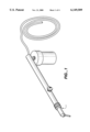
- FIG. 1 is a perspective view of the nozzle head shown installed on a microsandblaster.
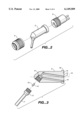
- FIG. 2 is a perspective drawing of the nozzle head assembly.
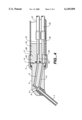
- FIG. 3 is a side view of the nozzle head.
- FIG. 4 is a crossection view of the nozzle head, locking ring and nozzle head adapter.
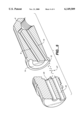
- FIG. 5 is a perspective view of the nozzle and nozzle head adapter.
- the improved nozzle head 1 comprising a nozzle head, nozzle to handpiece adapter and a locking ring to hold the nozzle head in direct contact with the nozzle adapter are illustrated installed on a microsandblaster in FIG. 1.
- FIG. 2 depicts a exploded view of the nozzle head assembly. Shown in FIG. 2 is the nozzle head 2, the nozzle adapter 3, and the locking ring 4.
- FIG. 3 depicts in greater detail the nozzle head 2 which comprises generally the nozzle body 5, an acceleration jet 6, an exit orifice tube 7, a mixing chamber 8, and a first 9 and second 10 longitudinal bore for transmission of a gas and abrasive laden stream. Also shown in FIG. 3 is an exit orifice tube mount 11 which allows for easy removal in the event the exit tube becomes clogged, damaged or worn. The mount is an optional feature and could be eliminated by gluing or press fitting the exit orifice tube directly into the nozzle body.
- FIG. 3 also depicts a nozzle head with an exit tube 7 angled downward at approximately a 60 degree angle. Various other angled tubes from zero degrees approaching to 180 degrees have been produced and are available depending upon the users applications. Now describing the nozzle body more specifically, FIG.
- the first longitudinal bore 9 in the preferred embodiment acts as a conduit for a pressurized gas source passing in fluid connection through the gas acceleration orifice or jet and terminating in the mixing chamber.
- the first longitudinal bore emanates at the rearward end 12 of the nozzle body and is located at the central longitudinal axis 13 of the nozzle body.
- the second longitudinal bore 10 acts as a conduit for a stream of abrasive laden gas.
- the second bore emanates at the rearward face of the nozzle body and is located radially from the central axis 13 of the nozzle body and is in fluid communication with a centrally located annular groove 14 located in the rearward face of the nozzle body.
- the second bore terminates in the mixing chamber and in the preferred embodiment has its central axis directed at the forward end 15 of the acceleration jet.
- a nozzle shoulder flange 16 At the rearward face of the nozzle body, shown in FIG. 3 is a nozzle shoulder flange 16. The flange extends radially beyond the outer sides of the nozzle head and provides a locking means to engage the nozzle locking ring and thereby secure the rearward face to the nozzle adapter.
- FIG. 4 the nozzle locking ring is shown installed.
- the nozzle locking ring slips over the exit orifice tube, over the nozzle body and engages the nozzle flange.
- the nozzle locking ring has internal threads on the inner diameter which of course corresponds to the outer diameter threads of the forward end of the nozzle adapter.
- the nozzle locking ring is knurled on its outer diameter surface to allow for easy hand tightening.
- FIG. 4 also depicts the nozzle adapter.
- the nozzle adapter comprises a nozzle adapter body 17, handpiece engagement means 18 and attachment means 19,20 for a first 21 and second 22 supply hose.
- the nozzle adapter body is formed as a ring member, has first 23 and second 24 bores which when engaged with the nozzle head provide for fluid communication between the first 9 and second 10 bores of the nozzle head and the first 21 and second 22 supply hoses.
- the first and second bores corresponding to the first and second bore diameters in the nozzle body.
- the nozzle adapter body has a forward end 25 and a rearward end 26.
- the first and second bores each have a pocket bore extending axially rearward.
- a first 19 and second 20 hollow plug is inserted and pressfit in each pocket bore,
- the first hollow plug serves as a slip-on means for a first supply line through which air is supplied.
- the second hollow plug serves as a slip-on means for a second supply line through which an abrasive laden gas stream passes.
- nozzle head and nozzle adapter are not shown in face to face engagement and the locking ring is not depicted.
- a gas passes through a first supply line through the first hollow plug and into the first 23 or center bore of the nozzle adapter and continues into the first 9 or center bore of the nozzle body eventually passing into the mixing chamber 8.
- a second supply line carrying a mixture of abrasive and a gas 27 passes through the second hollow plug through the second bore 24 of the nozzle adapter, and enters the corresponding second bore 10 of the nozzle body eventually passing into the mixing chamber where the two streams are mixed and then propelled through the exit orifice tube (not shown).
- the second bore of the nozzle adapter and the second bore of the nozzle body will no longer be axially aligned, they however remain in fluid communication through the annular groove 14 in the rearward face 12 of the nozzle body (see also FIG. 4).
- the nozzle body is fabricated of aluminum and the nozzle adapter of stainless steel. Although the exact materials are somewhat insignificant, applicant feel that the more wear resistant material should be used for the nozzle adapter as compared to the nozzle body. With this material preference, the easily replaced nozzle body will wear out before the nozzle adapter which is generally affixed to the handpiece.
- the annular groove could be located in either the nozzle adapter or the nozzle body. For machining ease, in the preferred embodiment the annular groove is located in the softer nozzle body material.
- the described removable nozzle head may be effectively used when the first and second supply line pressures are approximately equal.
- the first supply line When the second supply line is at atmospheric pressure, the first supply line must be sufficiently pressurized such that the gas passing through the acceleration jet causes a venturi effect thereby creating a vacuum on the second bores' and second supply line resulting in an urging of abrasive to flow into the mixing chamber.
- air pressures in the range of 25 to 100 psi or more produce a sufficient venturi effect to urge abrasive particles into the mixing chamber.
- the faces must be highly polished and aligned with high precision.
- flexible sealing o-rings may be located at the interface between the nozzle flange and the locking ring internal diameter flange. For simplicity and economical reasons o-rings are used in the preferred embodiment.
- all components of the nozzle are fabricated from materials with operating temperatures of at least 400 degrees Fahrenheit.
- the supply line could be changed without a problem if the supply streams are at roughly equal pressures.
- the mixing chamber could be eliminated under an alternative embodiment where the intended desire is to deliver two independent streams beyond the nozzle exit orifice.
- the nozzle head described herein can be easily modified to accomplish this intended objective by place the acceleration jet in airtight fluid communication with the exit orifice tube such that the stream delivered through the first bore can not mix with second supply stream until both streams exit the nozzle.
- the second stream delivered to the formerly labeled mixing chamber can be transported from the nozzle by second orifice exit tube, or by other means known to those skilled in the art such as longitudinal grooves along the sides of the first exit orifice tube.
- nozzle head provides a novel removable head which can be easily rotated, removed for repair, replacement or sterilization and can accommodate nozzles with varying angled orifice tubes.
Abstract
Description
Claims (21)
Priority Applications (1)
| Application Number | Priority Date | Filing Date | Title |
|---|---|---|---|
| US09/067,787 US6149509A (en) | 1995-11-27 | 1998-04-28 | Removable nozzle for a sandblaster handpiece |
Applications Claiming Priority (2)
| Application Number | Priority Date | Filing Date | Title |
|---|---|---|---|
| US08562528 US5765759C1 (en) | 1995-11-27 | 1995-11-27 | Removable nozzle for a sandblaster handpiece |
| US09/067,787 US6149509A (en) | 1995-11-27 | 1998-04-28 | Removable nozzle for a sandblaster handpiece |
Related Parent Applications (1)
| Application Number | Title | Priority Date | Filing Date |
|---|---|---|---|
| US08562528 Continuation US5765759C1 (en) | 1995-11-27 | 1995-11-27 | Removable nozzle for a sandblaster handpiece |
Publications (1)
| Publication Number | Publication Date |
|---|---|
| US6149509A true US6149509A (en) | 2000-11-21 |
Family
ID=24246646
Family Applications (2)
| Application Number | Title | Priority Date | Filing Date |
|---|---|---|---|
| US08562528 Expired - Lifetime US5765759C1 (en) | 1995-11-27 | 1995-11-27 | Removable nozzle for a sandblaster handpiece |
| US09/067,787 Expired - Lifetime US6149509A (en) | 1995-11-27 | 1998-04-28 | Removable nozzle for a sandblaster handpiece |
Family Applications Before (1)
| Application Number | Title | Priority Date | Filing Date |
|---|---|---|---|
| US08562528 Expired - Lifetime US5765759C1 (en) | 1995-11-27 | 1995-11-27 | Removable nozzle for a sandblaster handpiece |
Country Status (3)
| Country | Link |
|---|---|
| US (2) | US5765759C1 (en) |
| AU (1) | AU1125597A (en) |
| WO (1) | WO1997019755A1 (en) |
Cited By (10)
| Publication number | Priority date | Publication date | Assignee | Title |
|---|---|---|---|---|
| US20030037650A1 (en) * | 2001-08-27 | 2003-02-27 | Flow International Corporation | Apparatus for generating and manipulating a high-pressure fluid jet |
| US20040063386A1 (en) * | 2002-06-07 | 2004-04-01 | Wilhelm Hopf | Device for processing component part contours |
| US6729942B2 (en) | 2002-09-24 | 2004-05-04 | William H. Harris | Dental abrasion system |
| WO2004037109A2 (en) * | 2002-10-23 | 2004-05-06 | Kaltenbach & Voigt Gmbh & Co. Kg | Cannula for a medical or dental medical handpiece used for spraying an abrasive flow medium |
| US20040107810A1 (en) * | 2001-08-27 | 2004-06-10 | Flow International Corporation | Apparatus for generating a high-pressure fluid jet |
| US20060276112A1 (en) * | 2005-04-04 | 2006-12-07 | Jamie Davis | Hand held abrasive blaster |
| US20070165060A1 (en) * | 2005-11-19 | 2007-07-19 | Hammelmann Maschinenfabrik Gmbh | Nozzle head |
| US20070238400A1 (en) * | 2006-03-06 | 2007-10-11 | Carrell Wade J | Apparatus and method of removing a substance from a surface of a part |
| US7993135B2 (en) | 2004-10-14 | 2011-08-09 | Dentsply International, Inc. | Air polishing prophylaxis system |
| US20160113736A1 (en) * | 2013-06-05 | 2016-04-28 | Tohoku University | Hand piece for spraying powder |
Families Citing this family (20)
| Publication number | Priority date | Publication date | Assignee | Title |
|---|---|---|---|---|
| US6277128B1 (en) | 1998-07-11 | 2001-08-21 | J. Scott Muldner | Skin abrasion treatment device |
| WO2000067692A1 (en) | 1999-05-11 | 2000-11-16 | Dynatronics Corporation | Method and system for performing microabrasion and massage |
| US6582442B2 (en) | 2000-02-28 | 2003-06-24 | Dynatronics Corporation | Method and system for performing microabrasion |
| US6457974B1 (en) * | 1999-11-18 | 2002-10-01 | Parkell, Inc. | Intraoral dental abrading instrument |
| US6485303B1 (en) | 1999-11-18 | 2002-11-26 | Parkell, Inc. | Intraoral dental abrading instrument |
| US6206694B1 (en) * | 1999-11-24 | 2001-03-27 | Crystalmark Dental Systems, Inc. | Handpiece assembly for air abrasion |
| DE10114324B4 (en) | 2001-03-23 | 2005-03-10 | Ferton Holding Sa | Nozzle piece for a dantal abrasive blasting unit |
| US6616068B2 (en) * | 2001-04-20 | 2003-09-09 | Bayer Corporation | Spray nozzle for two-component air-assisted, low pressure spray systems |
| US6510970B2 (en) * | 2001-05-31 | 2003-01-28 | Ultradent Products, Inc. | Coupling adaptor for use with an air/water syringe tip of a fluid dispensing device |
| US20030129560A1 (en) * | 2001-10-31 | 2003-07-10 | Benjamin Atkin | Rotatable dental jet nozzle |
| US20040227021A1 (en) * | 2003-05-16 | 2004-11-18 | Bowles Fluidics Corporation | Tool-free, quick disconnect, nozzle assembly |
| DE10331583B3 (en) * | 2003-07-11 | 2004-07-15 | Ferton Holding S.A. | Nozzle piece for a dental powder stream device has several nozzle openings formed in the casing surface of the front end of a tubular partial length of the nozzle piece |
| EP2656814A2 (en) * | 2006-06-15 | 2013-10-30 | Koninklijke Philips N.V. | A droplet jet teeth cleaning system |
| GB0813494D0 (en) * | 2008-07-23 | 2008-08-27 | Osspray Ltd | Method |
| US20100081108A1 (en) * | 2008-09-30 | 2010-04-01 | Ultradent Products, Inc. | Three-way syringe adapter |
| FR2962323B1 (en) * | 2010-07-07 | 2012-08-10 | Conception Des Applic Des Tech Electroniques Soc Pour | NOZZLE FOR POLISHER |
| KR101803008B1 (en) * | 2011-05-04 | 2017-11-30 | 삼성디스플레이 주식회사 | Substrate processing apparatus and method of operating the same |
| ITTO20130363A1 (en) * | 2013-05-06 | 2014-11-07 | Biesse Spa | "WATER-JET" TYPE OPERATING HEAD FOR CUTTING OF MATERIALS WITH HIGH PRESSURE HYDRO-ABRASIVE JET |
| DE102016124212B4 (en) | 2016-12-13 | 2022-05-12 | Ferton Holding S.A. | mixing chamber and handpiece |
| DE102019125019B4 (en) * | 2019-09-17 | 2024-01-18 | Ferton Holding S.A. | Nozzle element, powder jet device and method for using a powder jet device |
Citations (28)
| Publication number | Priority date | Publication date | Assignee | Title |
|---|---|---|---|---|
| FR1027336A (en) * | 1949-11-09 | 1953-05-11 | Dental instrument handling head | |
| US2641087A (en) * | 1951-03-26 | 1953-06-09 | Howard A Greiser | Remote control valve for heavy duty sandblast hose |
| US2744361A (en) * | 1954-05-14 | 1956-05-08 | Tobin Arp Mfg Company | Scouring gun |
| US3164153A (en) * | 1961-09-20 | 1965-01-05 | Zorzi Carlo | Dental apparatus |
| US3421702A (en) * | 1967-08-02 | 1969-01-14 | Spraying Systems Co | Adjustable multiple fluid atomizing nozzle |
| US3905554A (en) * | 1973-10-24 | 1975-09-16 | Black & Decker Mfg Co | Convertible liquid spray nozzle |
| US3972123A (en) * | 1973-10-04 | 1976-08-03 | Black Robert B | Air-abrasive prophylaxis equipment |
| US4412402A (en) * | 1978-07-28 | 1983-11-01 | Cavitron Inc. | Equipment and method for delivering an abrasive-laden gas stream |
| US4478368A (en) * | 1982-06-11 | 1984-10-23 | Fluidyne Corporation | High velocity particulate containing fluid jet apparatus and process |
| US4522597A (en) * | 1980-10-17 | 1985-06-11 | Cooper Lasersonics, Inc. | Equipment and method for delivering an abrasive-laden gas stream |
| DE3242306C2 (en) * | 1982-11-16 | 1985-09-19 | Sata-Farbspritztechnik GmbH, 7140 Ludwigsburg | Pressure cup gun with pneumatic atomization |
| DE3101632C2 (en) * | 1981-01-20 | 1986-04-10 | Hans-Henning 4030 Ratingen Sasse | Spray device for liquid media |
| US4648840A (en) * | 1985-08-15 | 1987-03-10 | Conger Sr Stephen W | Dental polisher combining pressurized fluid and abrasive flow |
| US4676749A (en) * | 1984-03-08 | 1987-06-30 | Ems Electro Medical Systems, S.A. | Nozzle head for the hand piece of a dental prophylactic apparatus |
| DE8808494U1 (en) * | 1988-07-02 | 1988-09-15 | Toma-Maschinenbau Gmbh, 7450 Hechingen, De | |
| US4776794A (en) * | 1986-06-03 | 1988-10-11 | Moshe Meller | Cleaning instrument using premixed abrasive liquid |
| DE3841069A1 (en) * | 1988-02-18 | 1989-08-31 | Rotring Werke Riepe Kg | Spray gun for applying liquids |
| US4913353A (en) * | 1989-03-13 | 1990-04-03 | Ingersoll-Rand Company | Nozzle apparatus having angled orifice |
| US4941298A (en) * | 1988-09-28 | 1990-07-17 | Mark Fernwood | Rear reservoir micro sandblaster |
| EP0225193B1 (en) * | 1985-11-29 | 1990-08-22 | Robert Norman Borwick | Spraying nozzle |
| WO1991003640A1 (en) * | 1989-08-30 | 1991-03-21 | Robert Bosch Gmbh | Injection nozzle for diesel engines |
| US5054249A (en) * | 1988-11-23 | 1991-10-08 | Rankin George J | Method and apparatus for liquid-abrasive blast cleaning |
| US5082185A (en) * | 1990-10-02 | 1992-01-21 | Roussel Uclaf | Spray wand without liquid leakage |
| US5094615A (en) * | 1990-02-09 | 1992-03-10 | Young Dental Manufacturing Company | Dental polishing head and method |
| WO1992019173A1 (en) * | 1991-04-25 | 1992-11-12 | Blake Thomas S | Wet foam dental sandblaster |
| US5199229A (en) * | 1990-02-26 | 1993-04-06 | Thera Patent Gmbh & Co., Kg Gesellschaft Fur Industrielle Schutzrechte | Sand blasting device |
| US5350299A (en) * | 1992-03-27 | 1994-09-27 | American Dental Technologies, Inc. | Dental treatment system |
| US5468148A (en) * | 1993-12-28 | 1995-11-21 | Ricks; Melvin D. | Remotely controlled dental syringe |
Family Cites Families (1)
| Publication number | Priority date | Publication date | Assignee | Title |
|---|---|---|---|---|
| US4369607A (en) * | 1980-06-18 | 1983-01-25 | Cat Pumps Corporation | Sand blasting apparatus |
-
1995
- 1995-11-27 US US08562528 patent/US5765759C1/en not_active Expired - Lifetime
-
1996
- 1996-11-26 AU AU11255/97A patent/AU1125597A/en not_active Abandoned
- 1996-11-26 WO PCT/US1996/019040 patent/WO1997019755A1/en active Application Filing
-
1998
- 1998-04-28 US US09/067,787 patent/US6149509A/en not_active Expired - Lifetime
Patent Citations (29)
| Publication number | Priority date | Publication date | Assignee | Title |
|---|---|---|---|---|
| FR1027336A (en) * | 1949-11-09 | 1953-05-11 | Dental instrument handling head | |
| US2641087A (en) * | 1951-03-26 | 1953-06-09 | Howard A Greiser | Remote control valve for heavy duty sandblast hose |
| US2744361A (en) * | 1954-05-14 | 1956-05-08 | Tobin Arp Mfg Company | Scouring gun |
| US3164153A (en) * | 1961-09-20 | 1965-01-05 | Zorzi Carlo | Dental apparatus |
| US3421702A (en) * | 1967-08-02 | 1969-01-14 | Spraying Systems Co | Adjustable multiple fluid atomizing nozzle |
| US3972123A (en) * | 1973-10-04 | 1976-08-03 | Black Robert B | Air-abrasive prophylaxis equipment |
| US3905554A (en) * | 1973-10-24 | 1975-09-16 | Black & Decker Mfg Co | Convertible liquid spray nozzle |
| US4412402A (en) * | 1978-07-28 | 1983-11-01 | Cavitron Inc. | Equipment and method for delivering an abrasive-laden gas stream |
| US4522597A (en) * | 1980-10-17 | 1985-06-11 | Cooper Lasersonics, Inc. | Equipment and method for delivering an abrasive-laden gas stream |
| DE3101632C2 (en) * | 1981-01-20 | 1986-04-10 | Hans-Henning 4030 Ratingen Sasse | Spray device for liquid media |
| US4478368A (en) * | 1982-06-11 | 1984-10-23 | Fluidyne Corporation | High velocity particulate containing fluid jet apparatus and process |
| DE3242306C2 (en) * | 1982-11-16 | 1985-09-19 | Sata-Farbspritztechnik GmbH, 7140 Ludwigsburg | Pressure cup gun with pneumatic atomization |
| US4676749A (en) * | 1984-03-08 | 1987-06-30 | Ems Electro Medical Systems, S.A. | Nozzle head for the hand piece of a dental prophylactic apparatus |
| US4648840A (en) * | 1985-08-15 | 1987-03-10 | Conger Sr Stephen W | Dental polisher combining pressurized fluid and abrasive flow |
| EP0225193B1 (en) * | 1985-11-29 | 1990-08-22 | Robert Norman Borwick | Spraying nozzle |
| US4776794A (en) * | 1986-06-03 | 1988-10-11 | Moshe Meller | Cleaning instrument using premixed abrasive liquid |
| DE3841069A1 (en) * | 1988-02-18 | 1989-08-31 | Rotring Werke Riepe Kg | Spray gun for applying liquids |
| DE8808494U1 (en) * | 1988-07-02 | 1988-09-15 | Toma-Maschinenbau Gmbh, 7450 Hechingen, De | |
| US4941298A (en) * | 1988-09-28 | 1990-07-17 | Mark Fernwood | Rear reservoir micro sandblaster |
| US5054249A (en) * | 1988-11-23 | 1991-10-08 | Rankin George J | Method and apparatus for liquid-abrasive blast cleaning |
| US4913353A (en) * | 1989-03-13 | 1990-04-03 | Ingersoll-Rand Company | Nozzle apparatus having angled orifice |
| WO1991003640A1 (en) * | 1989-08-30 | 1991-03-21 | Robert Bosch Gmbh | Injection nozzle for diesel engines |
| US5094615A (en) * | 1990-02-09 | 1992-03-10 | Young Dental Manufacturing Company | Dental polishing head and method |
| US5199229A (en) * | 1990-02-26 | 1993-04-06 | Thera Patent Gmbh & Co., Kg Gesellschaft Fur Industrielle Schutzrechte | Sand blasting device |
| US5082185A (en) * | 1990-10-02 | 1992-01-21 | Roussel Uclaf | Spray wand without liquid leakage |
| WO1992019173A1 (en) * | 1991-04-25 | 1992-11-12 | Blake Thomas S | Wet foam dental sandblaster |
| US5203698A (en) * | 1991-04-25 | 1993-04-20 | Blake Thomas S | Wet foam sandblaster |
| US5350299A (en) * | 1992-03-27 | 1994-09-27 | American Dental Technologies, Inc. | Dental treatment system |
| US5468148A (en) * | 1993-12-28 | 1995-11-21 | Ricks; Melvin D. | Remotely controlled dental syringe |
Cited By (21)
| Publication number | Priority date | Publication date | Assignee | Title |
|---|---|---|---|---|
| US20080110312A1 (en) * | 2001-08-27 | 2008-05-15 | Flow International Corporation | Apparatus for generating and manipulating a high-pressure fluid jet |
| US20030037654A1 (en) * | 2001-08-27 | 2003-02-27 | Sciulli Felix M. | Apparatus for generating a high-pressure fluid jet |
| US7703363B2 (en) | 2001-08-27 | 2010-04-27 | Flow International Corporation | Apparatus for generating and manipulating a high-pressure fluid jet |
| US20030037650A1 (en) * | 2001-08-27 | 2003-02-27 | Flow International Corporation | Apparatus for generating and manipulating a high-pressure fluid jet |
| US20040107810A1 (en) * | 2001-08-27 | 2004-06-10 | Flow International Corporation | Apparatus for generating a high-pressure fluid jet |
| US7464630B2 (en) | 2001-08-27 | 2008-12-16 | Flow International Corporation | Apparatus for generating and manipulating a high-pressure fluid jet |
| US20040063386A1 (en) * | 2002-06-07 | 2004-04-01 | Wilhelm Hopf | Device for processing component part contours |
| US6939205B2 (en) * | 2002-06-07 | 2005-09-06 | Robert Bosch Gmbh | Device for processing component part contours |
| US6729942B2 (en) | 2002-09-24 | 2004-05-04 | William H. Harris | Dental abrasion system |
| WO2004037108A1 (en) * | 2002-10-23 | 2004-05-06 | Kaltenbach & Voigt Gmbh & Co. Kg | Tube for a medical or dental handpiece for spraying an abrasive flow medium |
| US20060121411A1 (en) * | 2002-10-23 | 2006-06-08 | Kaltenbach & Voigt Gmbh & Co. Kg | Cannula for a medical or dental medical handpiece used for spraying an abrasive flow medium |
| US20050272003A1 (en) * | 2002-10-23 | 2005-12-08 | Kaltenbach & Voigt Gmbh & Co. Kg | Cannula for a medical or dental-medical handpiece used for spraying an abrasive flow medium |
| WO2004037109A3 (en) * | 2002-10-23 | 2004-07-01 | Kaltenbach & Voigt | Cannula for a medical or dental medical handpiece used for spraying an abrasive flow medium |
| WO2004037109A2 (en) * | 2002-10-23 | 2004-05-06 | Kaltenbach & Voigt Gmbh & Co. Kg | Cannula for a medical or dental medical handpiece used for spraying an abrasive flow medium |
| US7993135B2 (en) | 2004-10-14 | 2011-08-09 | Dentsply International, Inc. | Air polishing prophylaxis system |
| US20060276112A1 (en) * | 2005-04-04 | 2006-12-07 | Jamie Davis | Hand held abrasive blaster |
| US7163449B2 (en) * | 2005-04-04 | 2007-01-16 | High Production Inc. | Hand held abrasive blaster |
| US20070165060A1 (en) * | 2005-11-19 | 2007-07-19 | Hammelmann Maschinenfabrik Gmbh | Nozzle head |
| US7780100B2 (en) * | 2005-11-19 | 2010-08-24 | Hammelmann Maschinenfabrik Gmbh | Nozzle head |
| US20070238400A1 (en) * | 2006-03-06 | 2007-10-11 | Carrell Wade J | Apparatus and method of removing a substance from a surface of a part |
| US20160113736A1 (en) * | 2013-06-05 | 2016-04-28 | Tohoku University | Hand piece for spraying powder |
Also Published As
| Publication number | Publication date |
|---|---|
| US5765759A (en) | 1998-06-16 |
| AU1125597A (en) | 1997-06-19 |
| WO1997019755A1 (en) | 1997-06-05 |
| US5765759C1 (en) | 2001-11-06 |
Similar Documents
| Publication | Publication Date | Title |
|---|---|---|
| US6149509A (en) | Removable nozzle for a sandblaster handpiece | |
| EP1414366B1 (en) | Dental sandblast tool | |
| US6004191A (en) | Particulate matter delivery device | |
| US4984984A (en) | Dental tool and nozzle therefor | |
| US5380201A (en) | Dental handpiece having cleaning unit | |
| US4648840A (en) | Dental polisher combining pressurized fluid and abrasive flow | |
| US4795343A (en) | Disposable rotary tool assembly for cleaning teeth | |
| US20050272003A1 (en) | Cannula for a medical or dental-medical handpiece used for spraying an abrasive flow medium | |
| JPH0728873B2 (en) | Handpiece nozzle head for tooth cleaning equipment | |
| US5242300A (en) | Nozzle for dental tool | |
| US4303392A (en) | Dental handpiece with quick disconnect coupling | |
| US6485303B1 (en) | Intraoral dental abrading instrument | |
| CA2417929A1 (en) | Hand-holdable gas/abrasion apparatus | |
| US5941702A (en) | Air-abrading tool | |
| CN110882071A (en) | Nozzle assembly of pneumatic dental sand blasting device | |
| US5312251A (en) | Dental implement | |
| US20030129560A1 (en) | Rotatable dental jet nozzle | |
| US6729942B2 (en) | Dental abrasion system | |
| US6457974B1 (en) | Intraoral dental abrading instrument | |
| US3525154A (en) | Handpiece with water spray | |
| US7101265B1 (en) | Universal improved particulate matter delivery device | |
| US6354924B1 (en) | Particulate matter delivery device commercial unit | |
| EP0015672A1 (en) | Vibratory device, work tool assembly, and dental scaler incorporating them | |
| JP3893488B2 (en) | Dental sandblast handpiece | |
| CN110883703A (en) | Prevent sand blasting machine of jam |
Legal Events
| Date | Code | Title | Description |
|---|---|---|---|
| STCF | Information on status: patent grant |
Free format text: PATENTED CASE |
|
| AS | Assignment |
Owner name: DANVILLE MANUFACTURING INC., CALIFORNIA Free format text: ASSIGNMENT CONFIRMATION;ASSIGNOR:DANVILLE MANUFACTURING INC.;REEL/FRAME:012506/0709 Effective date: 20020103 Owner name: DANVILLE MANUFACTURING INC., CALIFORNIA Free format text: ASSIGNMENT CONFRIRMATION;ASSIGNORS:BRUNS, CRAIG R.;BLAKE, THOMAS S.;FERNWOOD, MARK S.;REEL/FRAME:012506/0748 Effective date: 20020103 |
|
| FPAY | Fee payment |
Year of fee payment: 4 |
|
| AS | Assignment |
Owner name: DANVILLE MATERIALS, INC., CALIFORNIA Free format text: ASSIGNMENT OF ASSIGNORS INTEREST;ASSIGNOR:DANVILLE MANUFACTURING, INC.;REEL/FRAME:015139/0949 Effective date: 20030606 |
|
| FPAY | Fee payment |
Year of fee payment: 8 |
|
| FEPP | Fee payment procedure |
Free format text: PAYOR NUMBER ASSIGNED (ORIGINAL EVENT CODE: ASPN); ENTITY STATUS OF PATENT OWNER: SMALL ENTITY |
|
| FPAY | Fee payment |
Year of fee payment: 12 |
|
| AS | Assignment |
Owner name: DANVILLE MATERIALS, LLC, CALIFORNIA Free format text: ASSIGNMENT OF ASSIGNORS INTEREST;ASSIGNOR:DANVILLE MATERIALS, INC.;REEL/FRAME:031915/0521 Effective date: 20131219 Owner name: TRIANGLE MEZZANINE FUND LLLP, NORTH CAROLINA Free format text: SECURITY AGREEMENT;ASSIGNOR:DANVILLE MATERIALS, LLC;REEL/FRAME:031941/0307 Effective date: 20131219 |
|
| AS | Assignment |
Owner name: DANVILLE MATERIALS, LLC, CALIFORNIA Free format text: TERMINATION AND RELEASE OF SECURITY INTEREST IN PATENTS;ASSIGNOR:TRIANGLE MEZZANINE FUND LLLP;REEL/FRAME:037677/0441 Effective date: 20160201 |