US6149832A - Stabilized magnetorheological fluid compositions - Google Patents
Stabilized magnetorheological fluid compositions Download PDFInfo
- Publication number
- US6149832A US6149832A US09/178,755 US17875598A US6149832A US 6149832 A US6149832 A US 6149832A US 17875598 A US17875598 A US 17875598A US 6149832 A US6149832 A US 6149832A
- Authority
- US
- United States
- Prior art keywords
- particles
- fluid
- mean diameter
- liquid vehicle
- group
- Prior art date
- Legal status (The legal status is an assumption and is not a legal conclusion. Google has not performed a legal analysis and makes no representation as to the accuracy of the status listed.)
- Expired - Lifetime
Links
Images
Classifications
-
- H—ELECTRICITY
- H01—ELECTRIC ELEMENTS
- H01F—MAGNETS; INDUCTANCES; TRANSFORMERS; SELECTION OF MATERIALS FOR THEIR MAGNETIC PROPERTIES
- H01F1/00—Magnets or magnetic bodies characterised by the magnetic materials therefor; Selection of materials for their magnetic properties
- H01F1/44—Magnets or magnetic bodies characterised by the magnetic materials therefor; Selection of materials for their magnetic properties of magnetic liquids, e.g. ferrofluids
- H01F1/447—Magnets or magnetic bodies characterised by the magnetic materials therefor; Selection of materials for their magnetic properties of magnetic liquids, e.g. ferrofluids characterised by magnetoviscosity, e.g. magnetorheological, magnetothixotropic, magnetodilatant liquids
Definitions
- This invention pertains to magnetorheological fluid compositions that display good stability when subjected to ordinary sedimentation force or to strong centrifugal separation forces. This invention also provides such fluids that display such stability at temperatures of about 200° C. to 250° C.
- Magnetorheological (MR) fluids in general comprise a dispersion of low coercivity, ferromagnetic particles in a liquid vehicle. In the absence of a significant magnetic field, the fluid has an off-state viscosity, and in the presence of a suitable magnetic field (on-state), the fluid gels and requires a substantial torque or yield stress to commence flow.
- the particles are often small iron particles while a broad range of nonmagnetic liquids have been used or proposed for MR fluids.
- lubricants are mixed with the liquid vehicle when lubrication properties are required. Additives may also be employed to maintain the suspension of the particles in the liquid and to prevent coagulation of the particles.
- U.S. Pat. No. 5,667,715 to Foister and assigned to the assignee of this invention describes a family of magnetorheological (MR) fluids that are very useful because they display a high ratio of the torque output generated by the magnetically activated MR fluid to the torque or output for the same fluid in the unactivated or off state. It is usually desired that this ratio, called the "turn-up ratio", be maximized under given operating conditions because one usually wants the off-state viscosity to be of a relatively low value while a relatively high on-state (magnetic field on) yield stress is desired to accomplish the intended function of an MR device.
- the '715 patent MR materials provide high turn up ratio in part by utilizing magnetic particles of two distinct complementary sizes dispersed in a suitable liquid vehicle.
- MR fluids are being evaluated for use in shock absorbers and other suspension devices.
- MR fluids are also being evaluated for use in clutches such as cooling fan clutches and in powertrain transmissions.
- the operating temperatures normally do not exceed about 150° C., and only normal gravitation forces act on the fluid to induce separation of the suspended particles.
- Many of the compositions disclosed in the '715 patent are satisfactory for such relatively low temperature and low separation force applications.
- some clutch applications, particularly plate applications utilizing multiple flat plates involve centrifugal forces that cause particle separation.
- some automotive underhood applications involve operating temperatures of 200° C. to 250° C.
- This invention provides a magnetorheological fluid that is stable under prolonged exposure to forces that would otherwise separate the magnetic particles from the liquid vehicle.
- This MR fluid may also be formulated for stability at elevated temperatures of, e.g., 250° C.
- the fluid comprises a dispersion of low coercivity, generally spherical magnetic particles in a suitable liquid vehicle.
- the particles are carbonyl iron particles (i.e., made by decomposition of iron pentacarbonyl) with surface hydroxyl groups.
- the iron particles be subjected to a chemical reduction step, e.g., reduction in a hydrogen atmosphere, to promote the increase of hydroxyl groups on the surface of the particle and to soften the particles.
- a chemical reduction step e.g., reduction in a hydrogen atmosphere
- the iron particles are used in either one or two groups of particle sizes where each of said groups has a mean diameter in the range of about one to fifteen micrometers. At least one group of particles is small particles having a mean diameter in the range of one to two micrometers. The particles are further characterized by a standard deviation in diameters less than half of said mean value and a specific surface area greater than four square meters per cubic centimeter. The group of small particles (1 to 2 micrometers in mean diameter) preferably constitutes at least 20% by volume of said MR fluid. When a second group of iron particles is employed in the fluid, the mean diameter of the second group is preferably less than fifteen micrometers and at least three to four times the mean value of the small particle group. The specific surface area of the larger particles will usually be less than the area of then small particles. It is preferred that the larger particles also have surface hydroxyl groups.
- Suitable iron particles contain at least about 1 ⁇ 10 19 hydroxyl groups per square meter of particle surface area.
- the liquid vehicle is an important complementary constituent with respect to the magnetic particles. At least 80% by volume of the liquid is a composition incapable of forming hydrogen bonds with said hydroxyl group containing particles. The combination of surface hydroxyl groups bearing small particles and the nonpolar liquid vehicle is believed to permit the formation of a hydrogen bonded particle network resisting sedimentation and centrifugal separation.
- the liquid vehicle is a composition selected from the group consisting of aliphatic hydrocarbons and glycol esters.
- the liquid vehicle preferably has a viscosity at 40° C. no greater than about 100 cP.
- said liquid vehicle constituent when formulated with a dispersed group of small particles has a yield stress at 25° C. (in the absence of a magnetic field) of at least 200 Pa. When the MR fluid is expected to experience operating temperatures of 200° C., then it is preferred that the liquid vehicle have a molecular weight above 500 and preferably in the range of about 500 to 1000.
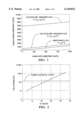
- FIG. 1 is a graph illustrating the shear stress/shear rate behavior of typical magnetorheological fluids.
- FIG. 2 is a graph showing the effect of solids concentration on yield stress of small particle magnetorheological fluids of this invention.
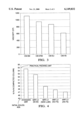
- FIG. 3 is a bar graph of viscosity in cP at 400° C. and 45% solids content of MR fluids of this invention.
- FIG. 4 is a bar graph of the final volume fraction of carbonyl iron particles after centrifuging of MR fluids of this invention.
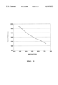
- FIG. 5 is a graph of yield stress in Pascals (Pa) of MR fluids of this invention versus the molecular weight of the polyalphaolefin vehicle.
- FIG. 1 is a graph of shear stress (arbitrary units) vs. shear rate (arbitrary units) illustrating the behavior of typical magnetorheological fluids and components. Most such fluids function essentially as Bingham fluids. In an ambient gravitational field but in the absence of a magnetic field, they display a shear stress that increases generally linearly as the shear rate on the fluid is increased. This property is indicated in FIG. 1. Bingham fluids display a shear stress at zero shear rate, whereas a Newtonian fluid (an idealized fluid) has no shear stress at zero shear rate. When MRF Bingham fluids are subjected to a magnetic field, the shear stress vs.
- shear rate relationship is transposed up the shear stress axis so that the shear stress required to commence shear of the fluid is substantially increased.
- the slope of the shear stress vs. shear rate curve for the MRF fluid in the applied magnetic field (in the "on” condition) is substantially parallel to the same curve for the "off" state MRF fluid.
- the values of the shear stress at zero shear rate for both the "on" state and “off” state fluids are the same values that are used in calculating the turn-up ratio which has been described above in this specification.
- a MR fluid using carbonyl iron particles of two different size range distributions.
- the small carbonyl particles have a mean diameter in the range of one to one and three-quarter micrometers and a standard deviation in the diameters of the small particle group that is less than half of the mean value of the diameters.
- the small carbonyl iron particles have a specific surface area that is greater than about 4 m 2 /cm 3 . It is preferred that the group of small particles constitute at least 20% by volume of the magnetorestrictive fluid.
- a further characteristic of the carbonyl iron particles employed in this invention is that they contain surface hydroxyl groups. The presence of such hydroxyl groups and a quantitative determination of hydroxyl group content can be made as will be described below.
- a second group of carbonyl iron particles is preferably employed in the practice of this invention where such particles have a mean diameter larger than one and three-quarters micrometers but less than about 15 micrometers.
- the larger particles have a mean diameter at least five times the mean diameter of the small particle group for maximum improvement of turn-up ratio.
- the standard deviation of the diameters of the larger group of particles be less than half of the mean value of the diameters of the larger particles.
- the small diameter carbonyl iron particles be employed in an amount of at least 20% by volume of the total fluid, the total particle content can be up to 45% to 50% by volume of the fluid.
- suitable iron particles from two sources.
- One source is ISP Technologies, Inc. and a second source is the BASF Company.
- the following tables illustrate suitable iron particle material designations and contain data representing the volume average particle diameter, the standard deviation of the average particle diameter, and the specific surface area for the respective particles.
- the particles are identified by the trade designation of their manufacturer. Some of the particles have been subjected to reducing atmospheres.
- the iron particles contain surface hydroxyl groups.
- the following is how a quantitative determination of hydroxyl group content can be undertaken.
- the hydroxyl surface concentration for the carbonyl Fe can be determined from absorption data. This number was obtained from chemisorption data of a reactive surfactant (an ethoxylated tallow amine, "T-15"). Essentially, a surfactant molecule reacts with an OH group on the Fe surface to produce an ether-type linkage plus one molecule of free water--a typical "condensation" reaction: M--OH+ROH ⁇ M--OR+H 2 O, where M is the Fe surface and ROH is the surfactant. This reaction can be monitored with near IR spectroscopy (i.e., following the depletion of surfactant in solution).
- hydrophilic fumed silica has from 3.5 to 4.5 ⁇ 10 18 OH groups per square meter of surface area (from Cab-O-Sil Fumed Silica Properties and Functions, p. 8, Cabot Corporation, 1987). So, the carbonyl Fe particles (BASF CM and HS) have roughly 10 to 15 times more OH groups per unit area than the fumed SiO 2 . This is consistent with what one would expect on the basis of the supposition that the yield stress in the subject self-stabilizing suspensions of small particle carbonyl Fe is the result of hydrogen bonding.
- the liquid vehicle of the MR fluid is also an important constituent. It is preferred that a preponderance of the vehicle, at least 80% by volume of the total liquid vehicle content, be a liquid that is formed of a composition that is generally incapable of forming hydrogen bonds with the hydroxyl group containing particles.
- Suitable liquid vehicles comprise materials such as the aliphatic hydrocarbons and glycol esters.
- An example of suitable aliphatic hydrocarbons is a family of polyalphaolefins (PAO) from the Mobil Corporation. These materials are generally based on the monomer 1-decene, CH 3 --(CH 2 ) 7 --CH ⁇ CH 2 .
- PAO polyalphaolefins
- the fluids designated SHF 21, SHF 41 and SHF 61 are suitable for low temperature applications. They are, in general, nonpolar fluids that do not interact substantially with the hydrogen bond among particles. For high temperature applications of the order of 200° C., it is preferred to use fluids such as SHF 82 and SHF 101 because they have a suitably low viscosity at 40° so as to contribute low off state viscosity to the fluid. On the other hand, they have a low evaporation rate at 250° C. which contributes to the stability of the MR fluid. Accordingly, polyalphaolefins having a molecular weight in the range of about 600 to 750 are preferred for use at temperatures of the order of 200° C.
- SHF 401 and SHF 1001 may be suitable.
- An example of another suitable liquid vehicle for the MR fluid formulations is Uniflex 206, a mixture of esters and di-esters from neopentyl glycol-based esterification of tall oil fatty acids, a product of Union Camp, Inc. The primary component of this liquid is neopentyl glycol dioleate (28% by volume of the total fluid).
- a source of pure neopentyl dioliate is Henkel Proeco 2965. Pure neopentyl dioliate offers the advantage of a lower viscosity than the Uniflex 206 mixture.
- a lubricant in the liquid vehicle.
- exemplary lubricants for use in the subject stabilized MR fluids. These lubricants may also be used in high temperature applications.
- MR fluid formulations it is also a practice in prior art MR fluid formulations to disperse fumed silicas as a thixotrope in the fluid.
- a high shear dispersion of ultrafine silica particles into the vehicle formed a thixotropic medium that stabilized the dispersion of the magnetic particles.
- U.S. Pat. No. 5,667,715. Again, however, in accordance with the practice of this invention, it is often possible to reduce or eliminate the fumed silica content and maintain a stable MR fluid.
- a MR fluid prepared in accordance with this invention need contain no more than about three percent by volume of fumed silica.
- the liquid vehicle and the solid magnetic particles are mixed for six to eight hours and then degassed before use.
- the properties of several such particle vehicle mixtures are described below.
- a feature of this invention is the stability of the small particle or small and large particle mixtures with the specific liquid vehicles in the MR fluids. It is found that when hydroxyl group-containing, carbonyl iron particles are suspended in suitable nonpolar liquids in accordance with this invention, the resulting fluids resist sedimentation under normal gravity and furthermore resist centrifugal separation in applications such as clutch applications.
- MRF fluids were prepared as follows to demonstrate the stability characteristic or these fluids. Each fluid was prepared to contain a total of 45% by volume carbonyl iron particles. Reference will be had to FIG. 4.
- a standard MR fluid was prepared to contain 22.5% by volume of BASF CM relatively large diameter iron particles and 22.5% by volume of BASF HS small diameter carbon particles in a liquid.
- the liquid consisted of, by volume, 20% SHF 41 PAO, 40% dioctyl sebacate and 40% Uniflex 192.
- Cab-o-Sil M5 fumed silica thixotropic additive was added in the amount of 7% by volume of the liquid.
- MRF-LV 50:50
- BASF CM large particles 50--50 mixture of BASF CM large particles
- BASF HS small particles 50--50 mixture of BASF CM large particles
- This fluid also contained 0.5% by volume of Cab-o-Sil M5 fumed silica.
- a third magnetorheological fluid was prepared, designated MRF-LV (new lube), containing a 50--50 mixture of BASF CM large particles and BASF HS small particles, 7% Cab-o-Sil fumed silica and the liquid consisted of 50% PAO SHF 82 and 50% Uniflex 206 lubricant.
- MRF-LV (no FS, for no fumed silica).
- MRF-LV (no FS) consisted of 50% BASF CM, 50% BASF HS particles and the liquid was entirely PAO SHF 82.
- MRF LV(2% FS) A fifth MRF was prepared, designated MRF LV(2% FS).
- This fluid consisted of BASF HS small particles, PAO SHF 82 and 2% Cab-o-Sil M5 fumed silica.
- the respective five MRF formulations were each centrifuged under a load of 500 times the force of gravity for one hour.
- the graph of FIG. 4 depicts the results of the compaction of the iron particles in the respective fluids after one hour of centrifuging.
- the standard MR fluid compacted such that the particles were in a column that was approximately 54.5% by volume particles, with the practical packing limit of the particles being about 55% by volume iron particles.
- the magnetic particles of the standard MR fluid segregated under the severe centrifuging operation nearly to the packing limit of the material itself. Such a fluid would not be preferred for use in an application in which the MR fluid would be subject to such centrifugal force.
- the basic MRF-LV material compacted somewhat less than the standard MRF. The final compaction was between 52% and 53%. The MRF-LV (new lube) material performed better. The compaction of this MR fluid was just under 49%. The MRF-LV with no fumed silica experienced a compaction of 47% to 48%, while the MRF-LV with 2% fumed silica underwent very little compaction. It reached a level of just under 47%, a material that would be suitable for use in an MRF application involving application of very severe centrifugal forces.
- FIG. 3 shows the "off" state dynamic viscosity and centipoise of MR fluids that are formulated to contain 45% solids of equal mixtures of large and small particle combinations in a polyalphaolefin vehicle, SHF-82.
- the respective combinations are the designations for the carbonyl iron particles found in the above table.
- the "on" shear stresses for these bimodal particle size fluids are several times as high as the "off” state viscosity.
- FIG. 5 illustrates the yield stresses produced by combinations of BASF HS small particles with varying molecular weight polyalphaolefins.
- the yield stress of these MR fluids decrease as the mw of the vehicle increases.
- the thermal stability of the fluid increases as the evaporation rate of the vehicle decreases.
- MRFC-1 consists of an equal mixture of BASF CM and BASF HS carbonyl Fe, in an amount which constitutes 45%/vol solids, suspended in SHF 82 polyalphaolefin, with 0. 5%/wt Cab-o-Sil fumed Si.
- MRFC-2 is also 45% solids/wt, but with a solid phase consisting entirely of BASF HS carbonyl Fe, suspended in SHF 82, with no fumed Si.
- the clutch was subjected to operating conditions which generated continuous use temperatures in the range of 120° C. to 200° C., with maximum temperatures exceeding 300° C. for short durations, for total times of up to 100 hours. Input speeds were such that centrifugal forces in excess of 500 g were experienced routinely. No deterioration in off state or magnetically-activated performance was observed. In addition, upon tear down at the conclusion of the tests, less than 2% change in solids volume fraction was measured in MR fluid taken from the clutch active areas, indicating negligible loss of the fluid phase due to volatization.
- the combination of carbonyl iron particles containing surface hydroxyl groups with a nonpolar solvent selected from the group consisting of aliphatic hydrocarbons and glycol esters provide magnetorheological fluids that resist particle separation.
- a nonpolar solvent selected from the group consisting of aliphatic hydrocarbons and glycol esters
- the polyalphaolefin or the glycol ester is selected to have a molecular weight such that its evaporation rate in percent per minute at 250° C. is in the range of about 0.1 to 0.13% per minute, the fluid displays such good stability at operating temperatures of the order of 200° C.
Abstract
Description
              TABLE 1
______________________________________
Properties of Carbonyl Iron Particle Distributions
           Volume
           Average               Specific
           Particle     Standard Surface
Material   Diameter     Deviation
                                 Area
Designation
           (μm)      (μm)  (m.sup.2 /cm.sup.3)
______________________________________
BASF HS*.sup.@
           1.61         0.489    4.15
ISP 3700.sup.@
           3.06         1.45     3.06
BASF SU.sup.%
           1.59         0.522    4.33
BASF HL.sup.@
           2.24         0.694    3.08
BASF CM**.sup.%
           10.0         5.24     1.06
BASF SM.sup.%
           2.35         0.857    3.14
______________________________________
 *Standard MRF "Small Particle" Component
 **Standard MRF "Large Particle" Component
 .sup.% Reduced Grade
 .sup.@ Unreduced Grade
              TABLE 2
______________________________________
Properties of Fluid Phase Components
(Preferred Low Volatility MRF Clutch Materials are Shaded)
Fluid   Viscosity  Evaporation Rate
Designation
        (cP @ 40° C.)
                   (%/min @ 250 ° C.)
                                Mw    Mw/Mn
______________________________________
SHF 21  4.2        --           283   1.00
SHF 41  14.8       1.59         434   1.01
SHF 61  23.7       0.704        549   1.04
SHF 82  39.2       0.128        635   1.04
SHF 101 68         0.106        723   1.05
SHF 401 340        0.0929       2719  1.55
Uniflex 206*
        28         0.371        632   --
______________________________________
 SHF refers to polyalphaolefins (PAO) from Mobil. These materials are base
 on the monomer 1decene. SHF 21 is primarily (97%) dimer, and 41 is
 primarily (90%) trimer. The remaining materials have increasingly broad M
 distributions, consisting of trimers, tetramers, pentamers, etc. The
 increments in the Mobil SHF product line (41, 61, etc.) are chosen on the
 basis of kinematic viscosity at 100° C. Thus, "SHF 41" has a
 kinematic viscosity of approximately 4 cst at  #  100° C., "SHF 61
 a kinematic viscosity of 6 cst, etc.
 *A mixture of esters and diesters from neopentyl glycol based
 esterification of tall oil fatty acids (Union Camp, Inc.). The primary
 component is neopentyl glycol dioleate (28%). A source of pure neopentyl
 dioleate is Henkel Proeco 2965. This material has the advantage of a
 somewhat lower (20%) viscosity than the more heterogeneous Uniflex 206.
______________________________________
Fluid      Viscosity,   Evaporation Rate
Designation
           CP @ 40° C.
                        %/min @ 250° C.
                                    Mw
______________________________________
Uniflex DOS*
           11.7         2.55        328
Uniflex 171**
           6.4          12.5        295
Uniflex 193***
           8.3          3.56        394
______________________________________
 *Dioctyl Sebacate, considered the lubricant base stock, essentially pure
 bis(2ethylhexyl) ester of decanedioic acid.
 **Methyl Tallate Ester, a lubricity additive. Primarily (93.7%) methyl
 linoleate, with 2.8% methyl stearate and 1.1% methyl palmitate. Also
 contains residual organic acid.
 ***Octyl Tallate Ester, a lubricity additive. Primarily 2ethylhexyl
 linoleate, with 2.6% oxidized branched ester, and traces of 2ethylhexyl
 oleate and 2ethyl-1-hexanol.
______________________________________
                              Yield Stress
         Viscosity   Off State
                              (Pa @ 1 Tesla
         (cP @       Yield    Applied Magnetic
MR Fluid 40° C.)
                     Stress (Pa)
                              Flux Density)
______________________________________
MRFC-1   751          514     69 × 10.sup.3
MRFC-2   616         1010     48 × 10.sup.3
______________________________________
Claims (9)
Priority Applications (1)
| Application Number | Priority Date | Filing Date | Title |
|---|---|---|---|
| US09/178,755 US6149832A (en) | 1998-10-26 | 1998-10-26 | Stabilized magnetorheological fluid compositions |
Applications Claiming Priority (1)
| Application Number | Priority Date | Filing Date | Title |
|---|---|---|---|
| US09/178,755 US6149832A (en) | 1998-10-26 | 1998-10-26 | Stabilized magnetorheological fluid compositions |
Publications (1)
| Publication Number | Publication Date |
|---|---|
| US6149832A true US6149832A (en) | 2000-11-21 |
Family
ID=22653835
Family Applications (1)
| Application Number | Title | Priority Date | Filing Date |
|---|---|---|---|
| US09/178,755 Expired - Lifetime US6149832A (en) | 1998-10-26 | 1998-10-26 | Stabilized magnetorheological fluid compositions |
Country Status (1)
| Country | Link |
|---|---|
| US (1) | US6149832A (en) |
Cited By (28)
| Publication number | Priority date | Publication date | Assignee | Title |
|---|---|---|---|---|
| US20030047705A1 (en) * | 1999-12-30 | 2003-03-13 | Iyengar Vardarajan R. | Magnetorheological compositions for use in magnetorheological fluids and method of preparing same |
| EP1296335A2 (en) * | 2001-09-21 | 2003-03-26 | Delphi Technologies, Inc. | Base liquid for magnetorheological fluid |
| US6547983B2 (en) * | 1999-12-14 | 2003-04-15 | Delphi Technologies, Inc. | Durable magnetorheological fluid compositions |
| EP1318528A2 (en) * | 2001-12-10 | 2003-06-11 | Delphi Technologies, Inc. | Stabilization of magnetorheological fluid suspensions using a mixture of organoclays |
| US6585092B1 (en) | 2002-01-09 | 2003-07-01 | General Motors Corporation | Magnetorheological fluid fan drive design for manufacturability |
| US6599439B2 (en) * | 1999-12-14 | 2003-07-29 | Delphi Technologies, Inc. | Durable magnetorheological fluid compositions |
| US6619444B2 (en) | 2001-04-04 | 2003-09-16 | Delphi Technologies, Inc. | Magnetorheological fluid stopper at electric motor |
| US20030209687A1 (en) * | 2000-04-07 | 2003-11-13 | Iyengar Vardarajan R. | Durable magnetorheological fluid |
| US6648115B2 (en) | 2001-10-15 | 2003-11-18 | General Motors Corporation | Method for slip power management of a controllable viscous fan drive |
| US20030221585A1 (en) * | 2002-05-29 | 2003-12-04 | Larson Thomas Marshall | Release agent and uses for same |
| WO2003107363A1 (en) * | 2002-06-14 | 2003-12-24 | University Of Pittsburgh Of The Commonwealth System For Higher Education | Magnetorheological fluids and related method of preparation |
| US20040217324A1 (en) * | 2003-05-02 | 2004-11-04 | Henry Hsu | Magnetorheological fluid compositions and prosthetic knees utilizing same |
| US20050045850A1 (en) * | 2003-08-25 | 2005-03-03 | Ulicny John C. | Oxidation-resistant magnetorheological fluid |
| US20050059563A1 (en) * | 2003-09-13 | 2005-03-17 | Sullivan William T. | Lubricating fluids with enhanced energy efficiency and durability |
| US20050139550A1 (en) * | 2003-12-31 | 2005-06-30 | Ulicny John C. | Oil spill recovery method using surface-treated iron powder |
| US20050242322A1 (en) * | 2004-05-03 | 2005-11-03 | Ottaviani Robert A | Clay-based magnetorheological fluid |
| US6982501B1 (en) | 2003-05-19 | 2006-01-03 | Materials Modification, Inc. | Magnetic fluid power generator device and method for generating power |
| US7007972B1 (en) | 2003-03-10 | 2006-03-07 | Materials Modification, Inc. | Method and airbag inflation apparatus employing magnetic fluid |
| US7070708B2 (en) | 2004-04-30 | 2006-07-04 | Delphi Technologies, Inc. | Magnetorheological fluid resistant to settling in natural rubber devices |
| US7200956B1 (en) | 2003-07-23 | 2007-04-10 | Materials Modification, Inc. | Magnetic fluid cushioning device for a footwear or shoe |
| US20070098903A1 (en) * | 2005-10-27 | 2007-05-03 | Georgia-Pacific Resins, Inc. | Non-aqueous coating formulation of low volatility |
| US20090057602A1 (en) * | 2007-08-01 | 2009-03-05 | Barber Daniel E | Non-settling glycol based magnetorheological fluids |
| US7560160B2 (en) | 2002-11-25 | 2009-07-14 | Materials Modification, Inc. | Multifunctional particulate material, fluid, and composition |
| US7670623B2 (en) | 2002-05-31 | 2010-03-02 | Materials Modification, Inc. | Hemostatic composition |
| US20100155649A1 (en) * | 2007-09-07 | 2010-06-24 | The University Of Akron | Molecule-based magnetic polymers and methods |
| US20100224820A1 (en) * | 2009-03-09 | 2010-09-09 | Gm Global Technology Operation, Inc. | Magnetorheological compositions including nonmagnetic material |
| US20140057748A1 (en) * | 2011-04-21 | 2014-02-27 | Aisaku Satomura | Hydraulic auto-tensioner |
| CN109036756A (en) * | 2018-09-17 | 2018-12-18 | 佛山皖和新能源科技有限公司 | A kind of preparation method of anti-settling magnetorheological fluid |
Citations (1)
| Publication number | Priority date | Publication date | Assignee | Title |
|---|---|---|---|---|
| US5667715A (en) * | 1996-04-08 | 1997-09-16 | General Motors Corporation | Magnetorheological fluids |
-
1998
- 1998-10-26 US US09/178,755 patent/US6149832A/en not_active Expired - Lifetime
Patent Citations (1)
| Publication number | Priority date | Publication date | Assignee | Title |
|---|---|---|---|---|
| US5667715A (en) * | 1996-04-08 | 1997-09-16 | General Motors Corporation | Magnetorheological fluids |
Cited By (50)
| Publication number | Priority date | Publication date | Assignee | Title |
|---|---|---|---|---|
| US6547983B2 (en) * | 1999-12-14 | 2003-04-15 | Delphi Technologies, Inc. | Durable magnetorheological fluid compositions |
| US6599439B2 (en) * | 1999-12-14 | 2003-07-29 | Delphi Technologies, Inc. | Durable magnetorheological fluid compositions |
| US6811717B2 (en) * | 1999-12-30 | 2004-11-02 | Delphi Technologies, Inc. | Magnetorheological compositions for use in magnetorheological fluids and method of preparing same |
| US20050064191A1 (en) * | 1999-12-30 | 2005-03-24 | Delphi Technologies, Inc. | Hydrophobic metal particles for magnetorheological compositions |
| US20030047705A1 (en) * | 1999-12-30 | 2003-03-13 | Iyengar Vardarajan R. | Magnetorheological compositions for use in magnetorheological fluids and method of preparing same |
| US6818143B2 (en) | 2000-04-07 | 2004-11-16 | Delphi Technologies, Inc. | Durable magnetorheological fluid |
| US20030209687A1 (en) * | 2000-04-07 | 2003-11-13 | Iyengar Vardarajan R. | Durable magnetorheological fluid |
| US6619444B2 (en) | 2001-04-04 | 2003-09-16 | Delphi Technologies, Inc. | Magnetorheological fluid stopper at electric motor |
| EP1296335A3 (en) * | 2001-09-21 | 2003-10-29 | Delphi Technologies, Inc. | Base liquid for magnetorheological fluid |
| US6638443B2 (en) * | 2001-09-21 | 2003-10-28 | Delphi Technologies, Inc. | Optimized synthetic base liquid for magnetorheological fluid formulations |
| EP1296335A2 (en) * | 2001-09-21 | 2003-03-26 | Delphi Technologies, Inc. | Base liquid for magnetorheological fluid |
| US6648115B2 (en) | 2001-10-15 | 2003-11-18 | General Motors Corporation | Method for slip power management of a controllable viscous fan drive |
| EP1318528A3 (en) * | 2001-12-10 | 2003-10-29 | Delphi Technologies, Inc. | Stabilization of magnetorheological fluid suspensions using a mixture of organoclays |
| EP1318528A2 (en) * | 2001-12-10 | 2003-06-11 | Delphi Technologies, Inc. | Stabilization of magnetorheological fluid suspensions using a mixture of organoclays |
| US6585092B1 (en) | 2002-01-09 | 2003-07-01 | General Motors Corporation | Magnetorheological fluid fan drive design for manufacturability |
| US6887305B2 (en) * | 2002-05-29 | 2005-05-03 | Exxonmobil Chemical Patents Inc. | Release agent and uses for same |
| US20030221585A1 (en) * | 2002-05-29 | 2003-12-04 | Larson Thomas Marshall | Release agent and uses for same |
| US7670623B2 (en) | 2002-05-31 | 2010-03-02 | Materials Modification, Inc. | Hemostatic composition |
| US6712990B1 (en) * | 2002-06-14 | 2004-03-30 | University Of Pittsburgh Of The Commonwealth System Of Higher Education | Magnetorheological fluids and related method of preparation |
| WO2003107363A1 (en) * | 2002-06-14 | 2003-12-24 | University Of Pittsburgh Of The Commonwealth System For Higher Education | Magnetorheological fluids and related method of preparation |
| US7560160B2 (en) | 2002-11-25 | 2009-07-14 | Materials Modification, Inc. | Multifunctional particulate material, fluid, and composition |
| US7007972B1 (en) | 2003-03-10 | 2006-03-07 | Materials Modification, Inc. | Method and airbag inflation apparatus employing magnetic fluid |
| US7335233B2 (en) | 2003-05-02 | 2008-02-26 | Ossur Hf | Magnetorheological fluid compositions and prosthetic knees utilizing same |
| US20040217324A1 (en) * | 2003-05-02 | 2004-11-04 | Henry Hsu | Magnetorheological fluid compositions and prosthetic knees utilizing same |
| US7101487B2 (en) | 2003-05-02 | 2006-09-05 | Ossur Engineering, Inc. | Magnetorheological fluid compositions and prosthetic knees utilizing same |
| US20060197051A1 (en) * | 2003-05-02 | 2006-09-07 | Henry Hsu | Magnetorheological fluid compositions and prosthetic knees utilizing same |
| US20060178753A1 (en) * | 2003-05-02 | 2006-08-10 | Henry Hsu | Magnetorheological fluid compositions and prosthetic knees utilizing same |
| US6982501B1 (en) | 2003-05-19 | 2006-01-03 | Materials Modification, Inc. | Magnetic fluid power generator device and method for generating power |
| US7200956B1 (en) | 2003-07-23 | 2007-04-10 | Materials Modification, Inc. | Magnetic fluid cushioning device for a footwear or shoe |
| US6929757B2 (en) | 2003-08-25 | 2005-08-16 | General Motors Corporation | Oxidation-resistant magnetorheological fluid |
| US20050045850A1 (en) * | 2003-08-25 | 2005-03-03 | Ulicny John C. | Oxidation-resistant magnetorheological fluid |
| US20050059563A1 (en) * | 2003-09-13 | 2005-03-17 | Sullivan William T. | Lubricating fluids with enhanced energy efficiency and durability |
| US7585823B2 (en) | 2003-09-13 | 2009-09-08 | Exxonmobil Chemical Patents Inc. | Lubricating fluids with enhanced energy efficiency and durability |
| US7303679B2 (en) | 2003-12-31 | 2007-12-04 | General Motors Corporation | Oil spill recovery method using surface-treated iron powder |
| US20050139550A1 (en) * | 2003-12-31 | 2005-06-30 | Ulicny John C. | Oil spill recovery method using surface-treated iron powder |
| US7070708B2 (en) | 2004-04-30 | 2006-07-04 | Delphi Technologies, Inc. | Magnetorheological fluid resistant to settling in natural rubber devices |
| US20050242322A1 (en) * | 2004-05-03 | 2005-11-03 | Ottaviani Robert A | Clay-based magnetorheological fluid |
| US20070098903A1 (en) * | 2005-10-27 | 2007-05-03 | Georgia-Pacific Resins, Inc. | Non-aqueous coating formulation of low volatility |
| US7566759B2 (en) | 2005-10-27 | 2009-07-28 | Georgia-Pacific Chemicals Llc | Non-aqueous coating formulation of low volatility |
| US8062541B2 (en) | 2007-08-01 | 2011-11-22 | Lord Corporation | Non-settling glycol based magnetorheological fluids |
| US20090057602A1 (en) * | 2007-08-01 | 2009-03-05 | Barber Daniel E | Non-settling glycol based magnetorheological fluids |
| US20100155649A1 (en) * | 2007-09-07 | 2010-06-24 | The University Of Akron | Molecule-based magnetic polymers and methods |
| US20100224820A1 (en) * | 2009-03-09 | 2010-09-09 | Gm Global Technology Operation, Inc. | Magnetorheological compositions including nonmagnetic material |
| CN102349117A (en) * | 2009-03-09 | 2012-02-08 | 通用汽车环球科技运作有限责任公司 | Magnetorheological compositions including nonmagnetic material |
| US8361341B2 (en) * | 2009-03-09 | 2013-01-29 | GM Global Technology Operations LLC | Magnetorheological compositions including nonmagnetic material |
| US20140057748A1 (en) * | 2011-04-21 | 2014-02-27 | Aisaku Satomura | Hydraulic auto-tensioner |
| US20160230852A1 (en) * | 2011-04-21 | 2016-08-11 | Ntn Corporation | Hydraulic auto-tensioner |
| US9423009B2 (en) * | 2011-04-21 | 2016-08-23 | Ntn Corporation | Hydraulic auto-tensioner |
| US9863510B2 (en) * | 2011-04-21 | 2018-01-09 | Ntn Corporation | Hydraulic auto-tensioner |
| CN109036756A (en) * | 2018-09-17 | 2018-12-18 | 佛山皖和新能源科技有限公司 | A kind of preparation method of anti-settling magnetorheological fluid |
Similar Documents
| Publication | Publication Date | Title |
|---|---|---|
| US6149832A (en) | Stabilized magnetorheological fluid compositions | |
| EP0801403B1 (en) | Magnetorheological fluids | |
| JP4741660B2 (en) | Magnetic liquid | |
| JP3241726B2 (en) | Magnetorheological fluid and method for producing the same | |
| US5900184A (en) | Method and magnetorheological fluid formulations for increasing the output of a magnetorheological fluid device | |
| RU2106710C1 (en) | Magnetorheological material | |
| US6932917B2 (en) | Magnetorheological fluids | |
| US20110121223A1 (en) | Magnetorheological fluids and methods of making and using the same | |
| US6824701B1 (en) | Magnetorheological fluids with an additive package | |
| EP1318528A2 (en) | Stabilization of magnetorheological fluid suspensions using a mixture of organoclays | |
| EP1439550B1 (en) | Glycol-based magnetorheological fluids with thickening agent | |
| US4251381A (en) | Pasty damping agent dispersion | |
| US6451219B1 (en) | Use of high surface area untreated fumed silica in MR fluid formulation | |
| DE60222353T2 (en) | Use of a diester in a magnetorheological fluid | |
| US6787058B2 (en) | Low-cost MR fluids with powdered iron | |
| EP1283531A2 (en) | Magnetorheological fluids with a molybdenum-amine complex | |
| EP1283532A2 (en) | Magnetorheological fluids with stearate and thiophosphate additives | |
| US20080185554A1 (en) | Treated magnetizable particles and methods of making and using the same | |
| EP1283530B1 (en) | Magnetorheological fluids | |
| EP1492133A1 (en) | Magnetorheological fluids with stearate and thiophosphate additives | |
| US6929756B2 (en) | Magnetorheological fluids with a molybdenum-amine complex | |
| US20050242322A1 (en) | Clay-based magnetorheological fluid |
Legal Events
| Date | Code | Title | Description |
|---|---|---|---|
| AS | Assignment |
Owner name: GENERAL MOTORS CORPORATION, MICHIGAN Free format text: ASSIGNMENT OF ASSIGNORS INTEREST;ASSIGNOR:FOISTER, ROBERT THOMAS;REEL/FRAME:009600/0009 Effective date: 19981015 |
|
| STCF | Information on status: patent grant |
Free format text: PATENTED CASE |
|
| FPAY | Fee payment |
Year of fee payment: 4 |
|
| FPAY | Fee payment |
Year of fee payment: 8 |
|
| AS | Assignment |
Owner name: GM GLOBAL TECHNOLOGY OPERATIONS, INC., MICHIGAN Free format text: ASSIGNMENT OF ASSIGNORS INTEREST;ASSIGNOR:GENERAL MOTORS CORPORATION;REEL/FRAME:022117/0047 Effective date: 20050119 Owner name: GM GLOBAL TECHNOLOGY OPERATIONS, INC.,MICHIGAN Free format text: ASSIGNMENT OF ASSIGNORS INTEREST;ASSIGNOR:GENERAL MOTORS CORPORATION;REEL/FRAME:022117/0047 Effective date: 20050119 |
|
| AS | Assignment |
Owner name: UNITED STATES DEPARTMENT OF THE TREASURY, DISTRICT Free format text: SECURITY AGREEMENT;ASSIGNOR:GM GLOBAL TECHNOLOGY OPERATIONS, INC.;REEL/FRAME:022201/0501 Effective date: 20081231 |
|
| AS | Assignment |
Owner name: CITICORP USA, INC. AS AGENT FOR BANK PRIORITY SECU Free format text: SECURITY AGREEMENT;ASSIGNOR:GM GLOBAL TECHNOLOGY OPERATIONS, INC.;REEL/FRAME:022556/0013 Effective date: 20090409 Owner name: CITICORP USA, INC. AS AGENT FOR HEDGE PRIORITY SEC Free format text: SECURITY AGREEMENT;ASSIGNOR:GM GLOBAL TECHNOLOGY OPERATIONS, INC.;REEL/FRAME:022556/0013 Effective date: 20090409 |
|
| AS | Assignment |
Owner name: GM GLOBAL TECHNOLOGY OPERATIONS, INC., MICHIGAN Free format text: RELEASE BY SECURED PARTY;ASSIGNOR:UNITED STATES DEPARTMENT OF THE TREASURY;REEL/FRAME:023238/0015 Effective date: 20090709 |
|
| XAS | Not any more in us assignment database |
Free format text: RELEASE BY SECURED PARTY;ASSIGNOR:UNITED STATES DEPARTMENT OF THE TREASURY;REEL/FRAME:023124/0383 |
|
| AS | Assignment |
Owner name: GM GLOBAL TECHNOLOGY OPERATIONS, INC., MICHIGAN Free format text: RELEASE BY SECURED PARTY;ASSIGNORS:CITICORP USA, INC. AS AGENT FOR BANK PRIORITY SECURED PARTIES;CITICORP USA, INC. AS AGENT FOR HEDGE PRIORITY SECURED PARTIES;REEL/FRAME:023127/0326 Effective date: 20090814 |
|
| AS | Assignment |
Owner name: UNITED STATES DEPARTMENT OF THE TREASURY, DISTRICT Free format text: SECURITY AGREEMENT;ASSIGNOR:GM GLOBAL TECHNOLOGY OPERATIONS, INC.;REEL/FRAME:023155/0922 Effective date: 20090710 |
|
| AS | Assignment |
Owner name: UAW RETIREE MEDICAL BENEFITS TRUST, MICHIGAN Free format text: SECURITY AGREEMENT;ASSIGNOR:GM GLOBAL TECHNOLOGY OPERATIONS, INC.;REEL/FRAME:023161/0864 Effective date: 20090710 |
|
| AS | Assignment |
Owner name: GM GLOBAL TECHNOLOGY OPERATIONS, INC., MICHIGAN Free format text: RELEASE BY SECURED PARTY;ASSIGNOR:UAW RETIREE MEDICAL BENEFITS TRUST;REEL/FRAME:025311/0680 Effective date: 20101026 Owner name: GM GLOBAL TECHNOLOGY OPERATIONS, INC., MICHIGAN Free format text: RELEASE BY SECURED PARTY;ASSIGNOR:UNITED STATES DEPARTMENT OF THE TREASURY;REEL/FRAME:025245/0273 Effective date: 20100420 |
|
| AS | Assignment |
Owner name: WILMINGTON TRUST COMPANY, DELAWARE Free format text: SECURITY AGREEMENT;ASSIGNOR:GM GLOBAL TECHNOLOGY OPERATIONS, INC.;REEL/FRAME:025327/0222 Effective date: 20101027 |
|
| AS | Assignment |
Owner name: GM GLOBAL TECHNOLOGY OPERATIONS LLC, MICHIGAN Free format text: CHANGE OF NAME;ASSIGNOR:GM GLOBAL TECHNOLOGY OPERATIONS, INC.;REEL/FRAME:025780/0795 Effective date: 20101202 |
|
| FPAY | Fee payment |
Year of fee payment: 12 |
|
| AS | Assignment |
Owner name: GM GLOBAL TECHNOLOGY OPERATIONS LLC, MICHIGAN Free format text: RELEASE BY SECURED PARTY;ASSIGNOR:WILMINGTON TRUST COMPANY;REEL/FRAME:034183/0680 Effective date: 20141017 |