US6149855A - Method of manufacturing a building material from volcanic magma - Google Patents
Method of manufacturing a building material from volcanic magma Download PDFInfo
- Publication number
- US6149855A US6149855A US08/281,520 US28152094A US6149855A US 6149855 A US6149855 A US 6149855A US 28152094 A US28152094 A US 28152094A US 6149855 A US6149855 A US 6149855A
- Authority
- US
- United States
- Prior art keywords
- magma
- volcanic
- building material
- flowing
- volcanic magma
- Prior art date
- Legal status (The legal status is an assumption and is not a legal conclusion. Google has not performed a legal analysis and makes no representation as to the accuracy of the status listed.)
- Expired - Fee Related
Links
Images

Classifications
-
- C—CHEMISTRY; METALLURGY
- C04—CEMENTS; CONCRETE; ARTIFICIAL STONE; CERAMICS; REFRACTORIES
- C04B—LIME, MAGNESIA; SLAG; CEMENTS; COMPOSITIONS THEREOF, e.g. MORTARS, CONCRETE OR LIKE BUILDING MATERIALS; ARTIFICIAL STONE; CERAMICS; REFRACTORIES; TREATMENT OF NATURAL STONE
- C04B32/00—Artificial stone not provided for in other groups of this subclass
- C04B32/005—Artificial stone obtained by melting at least part of the composition, e.g. metal
-
- B—PERFORMING OPERATIONS; TRANSPORTING
- B28—WORKING CEMENT, CLAY, OR STONE
- B28B—SHAPING CLAY OR OTHER CERAMIC COMPOSITIONS; SHAPING SLAG; SHAPING MIXTURES CONTAINING CEMENTITIOUS MATERIAL, e.g. PLASTER
- B28B1/00—Producing shaped prefabricated articles from the material
- B28B1/14—Producing shaped prefabricated articles from the material by simple casting, the material being neither forcibly fed nor positively compacted
-
- B—PERFORMING OPERATIONS; TRANSPORTING
- B28—WORKING CEMENT, CLAY, OR STONE
- B28B—SHAPING CLAY OR OTHER CERAMIC COMPOSITIONS; SHAPING SLAG; SHAPING MIXTURES CONTAINING CEMENTITIOUS MATERIAL, e.g. PLASTER
- B28B1/00—Producing shaped prefabricated articles from the material
- B28B1/54—Producing shaped prefabricated articles from the material specially adapted for producing articles from molten material, e.g. slag refractory ceramic materials
-
- B—PERFORMING OPERATIONS; TRANSPORTING
- B28—WORKING CEMENT, CLAY, OR STONE
- B28B—SHAPING CLAY OR OTHER CERAMIC COMPOSITIONS; SHAPING SLAG; SHAPING MIXTURES CONTAINING CEMENTITIOUS MATERIAL, e.g. PLASTER
- B28B17/00—Details of, or accessories for, apparatus for shaping the material; Auxiliary measures taken in connection with such shaping
- B28B17/02—Conditioning the material prior to shaping
-
- B—PERFORMING OPERATIONS; TRANSPORTING
- B28—WORKING CEMENT, CLAY, OR STONE
- B28B—SHAPING CLAY OR OTHER CERAMIC COMPOSITIONS; SHAPING SLAG; SHAPING MIXTURES CONTAINING CEMENTITIOUS MATERIAL, e.g. PLASTER
- B28B7/00—Moulds; Cores; Mandrels
- B28B7/0088—Moulds in which at least one surface of the moulded article serves as mould surface, e.g. moulding articles on or against a previously shaped article, between previously shaped articles
-
- B—PERFORMING OPERATIONS; TRANSPORTING
- B28—WORKING CEMENT, CLAY, OR STONE
- B28B—SHAPING CLAY OR OTHER CERAMIC COMPOSITIONS; SHAPING SLAG; SHAPING MIXTURES CONTAINING CEMENTITIOUS MATERIAL, e.g. PLASTER
- B28B7/00—Moulds; Cores; Mandrels
- B28B7/22—Moulds for making units for prefabricated buildings, i.e. units each comprising an important section of at least two limiting planes of a room or space, e.g. cells; Moulds for making prefabricated stair units
Definitions
- the present invention pertains generally to building materials and their method of manufacture, and more particularly to using flowing volcanic magma to make structures and material that is ordinarily made of wood, brick, stone, steel, concrete, glass and other materials, as well as to generate electricity.
- flowing volcanic magma is directed into molds or machinery in the fluid state to produce barges, wharves, breakwaters, fences, sound barriers, road paving, pipe, floors, walls, roofs, building block, structural foam, batt insulation, insulating board and fiber strand reinforcement for plastics, as well as used as a heat source for the generation of electricity.
- a main advantage of this invention is that many products can now be made with little or no material cost.
- magma is stronger and more resistant to chemical attack than concrete.
- An important advantage of this invention is that it can be used to generate electricity at very low cost.
- FIG. 1 is a cross-sectional view of a magma casting facility according to the present invention.
- FIG. 2 shows a perspective view of a dwelling constructed of precast parts made in the casting facility shown in FIG. 1.
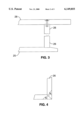
- FIGS. 3 and 4 show cross-sectional views of the joints and fastenings in the dwelling shown in FIG. 2.
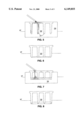
- FIGS. 5 through 8 show a sequence in cross-section of a barge construction method according to the invention.
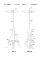
- FIG. 9 is a cross-sectional view showing a method of building a giant lava chimney over an underwater vent according to the invention.
- FIG. 10 shows in cross-section an underwater generator according to the invention.
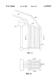
- FIG. 11 shows views of a flowing volcanic magma heated vertical boiler according to the invention.
- FIG. 12 is a cross-section of the flowing volcanic magma heated vertical boiler shown in FIG. 11 taken through line 12--12.
- FIG. 1 through FIG. 12 the apparatus generally shown in FIG. 1 through FIG. 12. It will be appreciated that the apparatus may vary as to configuration and as to details of the parts, and that the method may vary as to the specific steps and sequence, without departing from the basic concepts as disclosed herein.
- FIG. 1 shows a flowing volcanic magma casting facility in cross-section.
- Flowing volcanic magma is gated down an insulated delivery tube 21 to trough 22 which is continuous along the top corner of ganged, inclined slab molds 23.
- Molds 23 have water filled, hollow steel spacers between the faces of the slabs (not shown) to keep the steel from getting too hot and generate steam for additional use at the same time.
- Overhead traveling crane 24 inserts reinforcing, shuttering; helps close the molds; helps direct delivery tube 21; opens molds and removes the precast units to storage.
- FIG. 2 shows a perspective view of a dwelling constructed of precast panels made in the casting facility FIG. 1. It is assembled from four floor slabs 25; five wall slabs 26, one beam 27 and eight roof slabs 28. They are bolted at the joints as shown in FIGS. 3 and 4.
- FIG. 5 shows a cross section of a floating mold 29 that defines the deck 30, sides 31 and ends (not shown) that is being filled with flowing volcanic magma.
- Reference number 32 indicates bulkheads (longitudinal and transverse).
- FIG. 6 shows a cross-sectional view of the part 33 just cast in FIG. 5. It is supported by trapped air.
- FIG. 7 shows a cross-sectional view of a drydock 34 supporting part 33 by the deck overhang so that its skirts are above the floor of the drydock 34 and will be engaged by the closing pour.
- FIG. 8 shows the completed barge 35 floated out of the drydock 34.
- FIG. 9 is a cross-sectional view showing a method of building a giant lava tube to the ocean surface and above from an underwater flowing volcanic magma vent.
- a steel slip form cap assembly 48 is lowered over the flowing volcanic magma vent 49.
- the diameter of 48 is a function of the flowing volcanic magma flow rate and cooling rate.
- the flowing volcanic magma raises the cap and solidifies inside the perimeter where it is cold.
- the direction of growth can be changed by pulling up and sideways on riser 50 by use of the cable 52, its winch 53 and using thrusters or anchors on vessel 54.
- Flotation chamber 51 also helps hold the assembly upright.
- magma When the lava tube has risen well above sea level, magma can be directed into molds and otherwise processed in various barges surrounding the magma chimney island.
- FIG. 10 shows in cross-section, an underwater generator system.
- Volcanic magma is flowing from an underwater vent 36.
- a coaxial boiler tube 37 is inserted into the magma.
- a propeller 38 driven by the turbine 41 aids circulation of the boiler water.
- Just above the steam chest 39 is a collar 40 to limit penetration of the probe.
- the steam turbine 41 drives the generator 42 and the feed water trap 43 collects the condensate from the condenser 44.
- a cable 45 and winch 46 on vessel 47 position the underwater generator. Power cables (not shown) could go ashore underwater.
- FIG. 11 and FIG. 12 show a flowing volcanic magma heated vertical boiler that could be especially efficient where a good vertical drop is possible in the magma flow.
- Flowing volcanic magma enters at lava tube 52 and flows across and down through a grate of boiler header tubes 53 that are slightly larger in diameter and therefore closer together than the vertical boiler tubes 55. Solids that cannot pass the grate 53 as well as excess magma flow will be forced through gate 54.
- Boiler sides 56 can move in or out to help control flow and to allow access to the tubes. Circulation of water and steam to the steam chest 57 and heat transfer will be enhanced because this is a counter flow heat exchanger.
- the present invention is directed to harnessing and using flowing volcanic magma in ways that have not been used before.
- the description above contains many specificities, these should not be construed as limiting the scope of the invention but as merely providing illustrations of some of the presently preferred embodiments of this invention. Thus the scope of this invention should be determined by the appended claims and their legal equivalents.
Abstract
A method of manufacturing a building material includes the steps of directing molten volcanic magma from an underwater volcanic magma vent to a level above sea level via a tube formed from the magma; directing the molten volcanic magma into a mold on a floating barge; cooling the magma in the mold to form a building material; and removing the building material from the mold. The tube is formed by lowering a cap assembly over an underwater flowing volcanic magma vent and raising the cap such that the magam solidifies inside the cap perimeter where it is cold.
Description
1. Field of the Invention
The present invention pertains generally to building materials and their method of manufacture, and more particularly to using flowing volcanic magma to make structures and material that is ordinarily made of wood, brick, stone, steel, concrete, glass and other materials, as well as to generate electricity.
2. Description of the Background Art
In the past, structures have been made of wood, brick, stone, concrete, steel glass, plastic and other materials. Electricity has been generated by the use of geothermal, sun, nuclear and fossil fuel heat sources. Flowing volcanic magma is not known to have been used to produce building materials or electricity.
The main disadvantage of the prior materials and heat sources is the high cost to produce the raw materials, the refining costs plus transportation to manufacturing site. Geothermal heat depletes, the sun doesn't always shine, and nuclear plants have a special safety requirement cost.
Volcanic magma has been flowing almost continuously somewhere in the world from earliest times and will continue to do so for millennia to come. It is uncontrollable: nothing can stop it from erupting through the earth's surface. It has been useless at best and terribly destructive to life and property at its worst.
Therefore, there is a need for a method to tap flowing volcanic magma at low cost and to utilize this natural resource to produce many things, including electricity. The present invention satisfies that need, as well as others.
In accordance with the present invention, flowing volcanic magma is directed into molds or machinery in the fluid state to produce barges, wharves, breakwaters, fences, sound barriers, road paving, pipe, floors, walls, roofs, building block, structural foam, batt insulation, insulating board and fiber strand reinforcement for plastics, as well as used as a heat source for the generation of electricity.
A main advantage of this invention is that many products can now be made with little or no material cost.
Another advantage of this invention is that magma is stronger and more resistant to chemical attack than concrete.
An important advantage of this invention is that it can be used to generate electricity at very low cost.
The invention will be more fully understood by reference to the following drawings which are for illustrative purposes only, and where like reference numbers denote like parts:
FIG. 1 is a cross-sectional view of a magma casting facility according to the present invention.
FIG. 2 shows a perspective view of a dwelling constructed of precast parts made in the casting facility shown in FIG. 1.
FIGS. 3 and 4 show cross-sectional views of the joints and fastenings in the dwelling shown in FIG. 2.
FIGS. 5 through 8 show a sequence in cross-section of a barge construction method according to the invention.
FIG. 9 is a cross-sectional view showing a method of building a giant lava chimney over an underwater vent according to the invention.
FIG. 10 shows in cross-section an underwater generator according to the invention.
FIG. 11 shows views of a flowing volcanic magma heated vertical boiler according to the invention.
FIG. 12 is a cross-section of the flowing volcanic magma heated vertical boiler shown in FIG. 11 taken through line 12--12.
Referring more specifically to the drawings, for illustrative purposes the present invention is embodied in the apparatus generally shown in FIG. 1 through FIG. 12. It will be appreciated that the apparatus may vary as to configuration and as to details of the parts, and that the method may vary as to the specific steps and sequence, without departing from the basic concepts as disclosed herein.
FIG. 1 shows a flowing volcanic magma casting facility in cross-section. Flowing volcanic magma is gated down an insulated delivery tube 21 to trough 22 which is continuous along the top corner of ganged, inclined slab molds 23. Molds 23 have water filled, hollow steel spacers between the faces of the slabs (not shown) to keep the steel from getting too hot and generate steam for additional use at the same time. Overhead traveling crane 24 inserts reinforcing, shuttering; helps close the molds; helps direct delivery tube 21; opens molds and removes the precast units to storage.
FIG. 2 shows a perspective view of a dwelling constructed of precast panels made in the casting facility FIG. 1. It is assembled from four floor slabs 25; five wall slabs 26, one beam 27 and eight roof slabs 28. They are bolted at the joints as shown in FIGS. 3 and 4.
FIG. 5 shows a cross section of a floating mold 29 that defines the deck 30, sides 31 and ends (not shown) that is being filled with flowing volcanic magma. Reference number 32 indicates bulkheads (longitudinal and transverse).
FIG. 6 shows a cross-sectional view of the part 33 just cast in FIG. 5. It is supported by trapped air.
FIG. 7 shows a cross-sectional view of a drydock 34 supporting part 33 by the deck overhang so that its skirts are above the floor of the drydock 34 and will be engaged by the closing pour.
FIG. 8 shows the completed barge 35 floated out of the drydock 34.
FIG. 9 is a cross-sectional view showing a method of building a giant lava tube to the ocean surface and above from an underwater flowing volcanic magma vent. A steel slip form cap assembly 48 is lowered over the flowing volcanic magma vent 49. The diameter of 48 is a function of the flowing volcanic magma flow rate and cooling rate. The flowing volcanic magma raises the cap and solidifies inside the perimeter where it is cold. The direction of growth can be changed by pulling up and sideways on riser 50 by use of the cable 52, its winch 53 and using thrusters or anchors on vessel 54. Flotation chamber 51 also helps hold the assembly upright.
When the lava tube has risen well above sea level, magma can be directed into molds and otherwise processed in various barges surrounding the magma chimney island.
FIG. 10 shows in cross-section, an underwater generator system. Volcanic magma is flowing from an underwater vent 36. A coaxial boiler tube 37 is inserted into the magma. A propeller 38, driven by the turbine 41 aids circulation of the boiler water. Just above the steam chest 39 is a collar 40 to limit penetration of the probe. The steam turbine 41 drives the generator 42 and the feed water trap 43 collects the condensate from the condenser 44. A cable 45 and winch 46 on vessel 47 position the underwater generator. Power cables (not shown) could go ashore underwater.
FIG. 11 and FIG. 12 show a flowing volcanic magma heated vertical boiler that could be especially efficient where a good vertical drop is possible in the magma flow. Flowing volcanic magma enters at lava tube 52 and flows across and down through a grate of boiler header tubes 53 that are slightly larger in diameter and therefore closer together than the vertical boiler tubes 55. Solids that cannot pass the grate 53 as well as excess magma flow will be forced through gate 54. Boiler sides 56 can move in or out to help control flow and to allow access to the tubes. Circulation of water and steam to the steam chest 57 and heat transfer will be enhanced because this is a counter flow heat exchanger.
Accordingly, it can be seen that the present invention is directed to harnessing and using flowing volcanic magma in ways that have not been used before. Although the description above contains many specificities, these should not be construed as limiting the scope of the invention but as merely providing illustrations of some of the presently preferred embodiments of this invention. Thus the scope of this invention should be determined by the appended claims and their legal equivalents. Therefore, it will be appreciated that the scope of the present invention fully encompasses other embodiments which may become obvious to those skilled in the art, and that the scope of the present invention is accordingly to be limited by nothing other than the appended claims, in which reference to an element in the singular is not intended to mean "one and only one" unless explicitly so stated, but rather "one or more." All structural, chemical, and functional equivalents to the elements of the above-described preferred embodiment that are known to those of ordinary skill in the art are expressly incorporated herein by reference and are intended to be encompassed by the present claims. Moreover, it is not necessary for a device or method to address each and every problem sought to be solved by the present invention, for it to be encompassed by the present claims. Furthermore, no element, component, or method step in the present disclosure is intended to be dedicated to the public regardless of whether the element, component, or method step is explicitly recited in the claims. No claim element herein is to be construed under the provisions of 35 U.S.C. 112, sixth paragraph, unless the element is expressly recited using the phrase "means for."
Claims (1)
1. A method of manufacturing a building material, comprising:
directing molten volcanic magma from an underwater volcanic magma vent to a level above sea level via a tube formed from the magma;
directing the molten volcanic magma into a mold located on a floating barge;
cooling the magma in the mold to form a building material; and
removing the building material from the mold.
Priority Applications (2)
| Application Number | Priority Date | Filing Date | Title |
|---|---|---|---|
| US08/281,520 US6149855A (en) | 1994-07-28 | 1994-07-28 | Method of manufacturing a building material from volcanic magma |
| US09/687,368 US6551541B1 (en) | 1994-07-28 | 2000-10-13 | Method of manufacturing building material from volcanic magma |
Applications Claiming Priority (1)
| Application Number | Priority Date | Filing Date | Title |
|---|---|---|---|
| US08/281,520 US6149855A (en) | 1994-07-28 | 1994-07-28 | Method of manufacturing a building material from volcanic magma |
Related Child Applications (1)
| Application Number | Title | Priority Date | Filing Date |
|---|---|---|---|
| US09/687,368 Continuation-In-Part US6551541B1 (en) | 1994-07-28 | 2000-10-13 | Method of manufacturing building material from volcanic magma |
Publications (1)
| Publication Number | Publication Date |
|---|---|
| US6149855A true US6149855A (en) | 2000-11-21 |
Family
ID=23077649
Family Applications (1)
| Application Number | Title | Priority Date | Filing Date |
|---|---|---|---|
| US08/281,520 Expired - Fee Related US6149855A (en) | 1994-07-28 | 1994-07-28 | Method of manufacturing a building material from volcanic magma |
Country Status (1)
| Country | Link |
|---|---|
| US (1) | US6149855A (en) |
Cited By (8)
| Publication number | Priority date | Publication date | Assignee | Title |
|---|---|---|---|---|
| WO2003056075A1 (en) * | 2001-12-24 | 2003-07-10 | Ibeks Technologies Co., Ltd. | Multi-functional fiber containing natural magma-stone and manufacturing process for the same |
| US20040260303A1 (en) * | 2003-06-17 | 2004-12-23 | Carrison Harold F. | Apparatus and methods for delivering compounds into vertebrae for vertebroplasty |
| US20060063393A1 (en) * | 2000-08-21 | 2006-03-23 | Shaffer Edward O Ii | Organosilicate resins as hardmasks for organic polymer dielectrics in fabrication of microelectronic devices |
| US20070193182A1 (en) * | 2006-02-18 | 2007-08-23 | Ken Detjen | Lava and cement building block system |
| US20090013690A1 (en) * | 2007-07-13 | 2009-01-15 | Bruce Marshall | Hydrothermal energy and deep sea resource recovery system |
| US20100218454A1 (en) * | 2006-02-17 | 2010-09-02 | Ken Detjen | Lava and Cement Building Block System |
| US20140124355A1 (en) * | 2007-06-28 | 2014-05-08 | Nikola Lakic | Self-contained in-ground geothermal generator and heat exchanger with in-line pump |
| US11098926B2 (en) | 2007-06-28 | 2021-08-24 | Nikola Lakic | Self-contained in-ground geothermal generator and heat exchanger with in-line pump used in several alternative applications including the restoration of the salton sea |
-
1994
- 1994-07-28 US US08/281,520 patent/US6149855A/en not_active Expired - Fee Related
Non-Patent Citations (3)
| Title |
|---|
| J.D. Griggs, U.S. Geological survey, Apr. 1989. * |
| JP Abstract 04 203026 (Corresp. to App No. 02 334437) Abstract Published Nov. 1992. * |
| JP Abstract 04-203026 (Corresp. to App No. 02-334437) Abstract Published Nov. 1992. |
Cited By (11)
| Publication number | Priority date | Publication date | Assignee | Title |
|---|---|---|---|---|
| US20060063393A1 (en) * | 2000-08-21 | 2006-03-23 | Shaffer Edward O Ii | Organosilicate resins as hardmasks for organic polymer dielectrics in fabrication of microelectronic devices |
| WO2003056075A1 (en) * | 2001-12-24 | 2003-07-10 | Ibeks Technologies Co., Ltd. | Multi-functional fiber containing natural magma-stone and manufacturing process for the same |
| US20040260303A1 (en) * | 2003-06-17 | 2004-12-23 | Carrison Harold F. | Apparatus and methods for delivering compounds into vertebrae for vertebroplasty |
| US20100218454A1 (en) * | 2006-02-17 | 2010-09-02 | Ken Detjen | Lava and Cement Building Block System |
| US20070193182A1 (en) * | 2006-02-18 | 2007-08-23 | Ken Detjen | Lava and cement building block system |
| US7721505B2 (en) | 2006-02-18 | 2010-05-25 | Ken Detjen | Lava and cement building block system |
| US20140124355A1 (en) * | 2007-06-28 | 2014-05-08 | Nikola Lakic | Self-contained in-ground geothermal generator and heat exchanger with in-line pump |
| US9978466B2 (en) * | 2007-06-28 | 2018-05-22 | Nikola Lakic | Self-contained in-ground geothermal generator and heat exchanger with in-line pump |
| US11098926B2 (en) | 2007-06-28 | 2021-08-24 | Nikola Lakic | Self-contained in-ground geothermal generator and heat exchanger with in-line pump used in several alternative applications including the restoration of the salton sea |
| US20090013690A1 (en) * | 2007-07-13 | 2009-01-15 | Bruce Marshall | Hydrothermal energy and deep sea resource recovery system |
| US8001784B2 (en) * | 2007-07-13 | 2011-08-23 | Bruce Marshall | Hydrothermal energy and deep sea resource recovery system |
Similar Documents
| Publication | Publication Date | Title |
|---|---|---|
| US4014177A (en) | Marine pier having deeply submerged storage container | |
| CA2679281C (en) | Underwater suspended tunnel | |
| US6149855A (en) | Method of manufacturing a building material from volcanic magma | |
| JP2000506573A (en) | Ice complex body | |
| CN102086634B (en) | Marine underwater assembled water intake and construction method thereof | |
| US4475535A (en) | Segregated solar pond | |
| US6551541B1 (en) | Method of manufacturing building material from volcanic magma | |
| Glerum | Developments in immersed tunnelling in Holland | |
| US10400407B2 (en) | Modular wave-break and bulkhead system | |
| EP0701643A1 (en) | A flow compensation device for bridge pillars | |
| CN209194552U (en) | A kind of combined cofferdam for bridge foundation construction | |
| CN109080782B (en) | Large-scale chinampa on sea | |
| Hutchinson et al. | Case history of a spaced pile breakwater at half moon bay marina auckland, new zealand | |
| JP2700185B2 (en) | Transport pipeline | |
| CN109386087A (en) | Prefabricated hollow round pipe cast-in-place concrete building floor | |
| SU1534135A1 (en) | Method and apparatus for preparing a beach for service | |
| SU1127939A1 (en) | Method for erecting water engineering plant with power plant building on rock base | |
| CN211440506U (en) | Steam curing pool | |
| CN115136915B (en) | Ring beam | |
| CN209950137U (en) | A collection fortune fish system for improving cross fish efficiency | |
| Watson | Building materials from volcanic magma | |
| JP2003074074A (en) | Retaining wall, water quality purifying device and water quality purifying method | |
| JPH10129580A (en) | Semisubmergible offshore structure supported by hollow floating bag | |
| JP2024508480A (en) | Floating concrete block structure and its manufacturing method | |
| JPH0144954Y2 (en) |
Legal Events
| Date | Code | Title | Description |
|---|---|---|---|
| FPAY | Fee payment |
Year of fee payment: 4 |
|
| FPAY | Fee payment |
Year of fee payment: 8 |
|
| REMI | Maintenance fee reminder mailed | ||
| LAPS | Lapse for failure to pay maintenance fees | ||
| STCH | Information on status: patent discontinuation |
Free format text: PATENT EXPIRED DUE TO NONPAYMENT OF MAINTENANCE FEES UNDER 37 CFR 1.362 |
|
| FP | Lapsed due to failure to pay maintenance fee |
Effective date: 20121121 |