US6149996A - Molded tip and tubing and method of making same - Google Patents
Molded tip and tubing and method of making same Download PDFInfo
- Publication number
- US6149996A US6149996A US09/007,867 US786798A US6149996A US 6149996 A US6149996 A US 6149996A US 786798 A US786798 A US 786798A US 6149996 A US6149996 A US 6149996A
- Authority
- US
- United States
- Prior art keywords
- tubing
- tip
- molded tip
- assembly
- molded
- Prior art date
- Legal status (The legal status is an assumption and is not a legal conclusion. Google has not performed a legal analysis and makes no representation as to the accuracy of the status listed.)
- Expired - Lifetime
Links
- 238000004519 manufacturing process Methods 0.000 title abstract description 5
- 239000000463 material Substances 0.000 claims description 35
- 238000002844 melting Methods 0.000 claims description 22
- 230000008018 melting Effects 0.000 claims description 22
- 229920002614 Polyether block amide Polymers 0.000 claims description 17
- 238000000034 method Methods 0.000 claims description 13
- 229920001169 thermoplastic Polymers 0.000 claims description 12
- 239000004416 thermosoftening plastic Substances 0.000 claims description 12
- 238000001816 cooling Methods 0.000 claims description 4
- 229920002635 polyurethane Polymers 0.000 claims description 4
- 239000004814 polyurethane Substances 0.000 claims description 4
- 229910000831 Steel Inorganic materials 0.000 claims description 3
- 239000004433 Thermoplastic polyurethane Substances 0.000 claims description 3
- 229910052782 aluminium Inorganic materials 0.000 claims description 3
- XAGFODPZIPBFFR-UHFFFAOYSA-N aluminium Chemical compound [Al] XAGFODPZIPBFFR-UHFFFAOYSA-N 0.000 claims description 3
- 229920001971 elastomer Polymers 0.000 claims description 3
- 239000000806 elastomer Substances 0.000 claims description 3
- 239000010959 steel Substances 0.000 claims description 3
- 229920002803 thermoplastic polyurethane Polymers 0.000 claims description 3
- 229910052751 metal Inorganic materials 0.000 claims description 2
- 239000002184 metal Substances 0.000 claims description 2
- 238000004381 surface treatment Methods 0.000 description 8
- 239000004696 Poly ether ether ketone Substances 0.000 description 4
- 229920002530 polyetherether ketone Polymers 0.000 description 4
- RYECOJGRJDOGPP-UHFFFAOYSA-N Ethylurea Chemical compound CCNC(N)=O RYECOJGRJDOGPP-UHFFFAOYSA-N 0.000 description 3
- JUPQTSLXMOCDHR-UHFFFAOYSA-N benzene-1,4-diol;bis(4-fluorophenyl)methanone Chemical compound OC1=CC=C(O)C=C1.C1=CC(F)=CC=C1C(=O)C1=CC=C(F)C=C1 JUPQTSLXMOCDHR-UHFFFAOYSA-N 0.000 description 3
- 239000007788 liquid Substances 0.000 description 3
- 230000004048 modification Effects 0.000 description 3
- 238000012986 modification Methods 0.000 description 3
- 238000000465 moulding Methods 0.000 description 3
- 239000000853 adhesive Substances 0.000 description 2
- 230000001070 adhesive effect Effects 0.000 description 2
- 230000008901 benefit Effects 0.000 description 2
- 230000015556 catabolic process Effects 0.000 description 2
- 238000010276 construction Methods 0.000 description 2
- 238000006731 degradation reaction Methods 0.000 description 2
- 238000010438 heat treatment Methods 0.000 description 2
- 238000001746 injection moulding Methods 0.000 description 2
- 239000011347 resin Substances 0.000 description 2
- 229920005989 resin Polymers 0.000 description 2
- 239000000126 substance Substances 0.000 description 2
- 239000000835 fiber Substances 0.000 description 1
- 230000003252 repetitive effect Effects 0.000 description 1
- 238000005096 rolling process Methods 0.000 description 1
- 238000007789 sealing Methods 0.000 description 1
- 239000007787 solid Substances 0.000 description 1
- 239000012899 standard injection Substances 0.000 description 1
- 230000003746 surface roughness Effects 0.000 description 1
- 238000012876 topography Methods 0.000 description 1
Images
Classifications
-
- A—HUMAN NECESSITIES
- A61—MEDICAL OR VETERINARY SCIENCE; HYGIENE
- A61M—DEVICES FOR INTRODUCING MEDIA INTO, OR ONTO, THE BODY; DEVICES FOR TRANSDUCING BODY MEDIA OR FOR TAKING MEDIA FROM THE BODY; DEVICES FOR PRODUCING OR ENDING SLEEP OR STUPOR
- A61M25/00—Catheters; Hollow probes
- A61M25/0009—Making of catheters or other medical or surgical tubes
- A61M25/001—Forming the tip of a catheter, e.g. bevelling process, join or taper
-
- A—HUMAN NECESSITIES
- A61—MEDICAL OR VETERINARY SCIENCE; HYGIENE
- A61M—DEVICES FOR INTRODUCING MEDIA INTO, OR ONTO, THE BODY; DEVICES FOR TRANSDUCING BODY MEDIA OR FOR TAKING MEDIA FROM THE BODY; DEVICES FOR PRODUCING OR ENDING SLEEP OR STUPOR
- A61M25/00—Catheters; Hollow probes
- A61M25/0067—Catheters; Hollow probes characterised by the distal end, e.g. tips
- A61M25/0068—Static characteristics of the catheter tip, e.g. shape, atraumatic tip, curved tip or tip structure
- A61M25/0069—Tip not integral with tube
-
- A—HUMAN NECESSITIES
- A61—MEDICAL OR VETERINARY SCIENCE; HYGIENE
- A61M—DEVICES FOR INTRODUCING MEDIA INTO, OR ONTO, THE BODY; DEVICES FOR TRANSDUCING BODY MEDIA OR FOR TAKING MEDIA FROM THE BODY; DEVICES FOR PRODUCING OR ENDING SLEEP OR STUPOR
- A61M25/00—Catheters; Hollow probes
- A61M25/0067—Catheters; Hollow probes characterised by the distal end, e.g. tips
- A61M25/0068—Static characteristics of the catheter tip, e.g. shape, atraumatic tip, curved tip or tip structure
-
- A—HUMAN NECESSITIES
- A61—MEDICAL OR VETERINARY SCIENCE; HYGIENE
- A61M—DEVICES FOR INTRODUCING MEDIA INTO, OR ONTO, THE BODY; DEVICES FOR TRANSDUCING BODY MEDIA OR FOR TAKING MEDIA FROM THE BODY; DEVICES FOR PRODUCING OR ENDING SLEEP OR STUPOR
- A61M25/00—Catheters; Hollow probes
- A61M25/0067—Catheters; Hollow probes characterised by the distal end, e.g. tips
- A61M25/008—Strength or flexibility characteristics of the catheter tip
-
- Y—GENERAL TAGGING OF NEW TECHNOLOGICAL DEVELOPMENTS; GENERAL TAGGING OF CROSS-SECTIONAL TECHNOLOGIES SPANNING OVER SEVERAL SECTIONS OF THE IPC; TECHNICAL SUBJECTS COVERED BY FORMER USPC CROSS-REFERENCE ART COLLECTIONS [XRACs] AND DIGESTS
- Y10—TECHNICAL SUBJECTS COVERED BY FORMER USPC
- Y10T—TECHNICAL SUBJECTS COVERED BY FORMER US CLASSIFICATION
- Y10T428/00—Stock material or miscellaneous articles
- Y10T428/13—Hollow or container type article [e.g., tube, vase, etc.]
- Y10T428/1352—Polymer or resin containing [i.e., natural or synthetic]
- Y10T428/139—Open-ended, self-supporting conduit, cylinder, or tube-type article
-
- Y—GENERAL TAGGING OF NEW TECHNOLOGICAL DEVELOPMENTS; GENERAL TAGGING OF CROSS-SECTIONAL TECHNOLOGIES SPANNING OVER SEVERAL SECTIONS OF THE IPC; TECHNICAL SUBJECTS COVERED BY FORMER USPC CROSS-REFERENCE ART COLLECTIONS [XRACs] AND DIGESTS
- Y10—TECHNICAL SUBJECTS COVERED BY FORMER USPC
- Y10T—TECHNICAL SUBJECTS COVERED BY FORMER US CLASSIFICATION
- Y10T428/00—Stock material or miscellaneous articles
- Y10T428/24—Structurally defined web or sheet [e.g., overall dimension, etc.]
- Y10T428/24355—Continuous and nonuniform or irregular surface on layer or component [e.g., roofing, etc.]
- Y10T428/24372—Particulate matter
- Y10T428/24405—Polymer or resin [e.g., natural or synthetic rubber, etc.]
-
- Y—GENERAL TAGGING OF NEW TECHNOLOGICAL DEVELOPMENTS; GENERAL TAGGING OF CROSS-SECTIONAL TECHNOLOGIES SPANNING OVER SEVERAL SECTIONS OF THE IPC; TECHNICAL SUBJECTS COVERED BY FORMER USPC CROSS-REFERENCE ART COLLECTIONS [XRACs] AND DIGESTS
- Y10—TECHNICAL SUBJECTS COVERED BY FORMER USPC
- Y10T—TECHNICAL SUBJECTS COVERED BY FORMER US CLASSIFICATION
- Y10T428/00—Stock material or miscellaneous articles
- Y10T428/24—Structurally defined web or sheet [e.g., overall dimension, etc.]
- Y10T428/24479—Structurally defined web or sheet [e.g., overall dimension, etc.] including variation in thickness
- Y10T428/24488—Differential nonuniformity at margin
-
- Y—GENERAL TAGGING OF NEW TECHNOLOGICAL DEVELOPMENTS; GENERAL TAGGING OF CROSS-SECTIONAL TECHNOLOGIES SPANNING OVER SEVERAL SECTIONS OF THE IPC; TECHNICAL SUBJECTS COVERED BY FORMER USPC CROSS-REFERENCE ART COLLECTIONS [XRACs] AND DIGESTS
- Y10—TECHNICAL SUBJECTS COVERED BY FORMER USPC
- Y10T—TECHNICAL SUBJECTS COVERED BY FORMER US CLASSIFICATION
- Y10T428/00—Stock material or miscellaneous articles
- Y10T428/24—Structurally defined web or sheet [e.g., overall dimension, etc.]
- Y10T428/24479—Structurally defined web or sheet [e.g., overall dimension, etc.] including variation in thickness
- Y10T428/24496—Foamed or cellular component
- Y10T428/24504—Component comprises a polymer [e.g., rubber, etc.]
- Y10T428/24512—Polyurethane
-
- Y—GENERAL TAGGING OF NEW TECHNOLOGICAL DEVELOPMENTS; GENERAL TAGGING OF CROSS-SECTIONAL TECHNOLOGIES SPANNING OVER SEVERAL SECTIONS OF THE IPC; TECHNICAL SUBJECTS COVERED BY FORMER USPC CROSS-REFERENCE ART COLLECTIONS [XRACs] AND DIGESTS
- Y10—TECHNICAL SUBJECTS COVERED BY FORMER USPC
- Y10T—TECHNICAL SUBJECTS COVERED BY FORMER US CLASSIFICATION
- Y10T428/00—Stock material or miscellaneous articles
- Y10T428/24—Structurally defined web or sheet [e.g., overall dimension, etc.]
- Y10T428/24479—Structurally defined web or sheet [e.g., overall dimension, etc.] including variation in thickness
- Y10T428/24521—Structurally defined web or sheet [e.g., overall dimension, etc.] including variation in thickness with component conforming to contour of nonplanar surface
-
- Y—GENERAL TAGGING OF NEW TECHNOLOGICAL DEVELOPMENTS; GENERAL TAGGING OF CROSS-SECTIONAL TECHNOLOGIES SPANNING OVER SEVERAL SECTIONS OF THE IPC; TECHNICAL SUBJECTS COVERED BY FORMER USPC CROSS-REFERENCE ART COLLECTIONS [XRACs] AND DIGESTS
- Y10—TECHNICAL SUBJECTS COVERED BY FORMER USPC
- Y10T—TECHNICAL SUBJECTS COVERED BY FORMER US CLASSIFICATION
- Y10T428/00—Stock material or miscellaneous articles
- Y10T428/24—Structurally defined web or sheet [e.g., overall dimension, etc.]
- Y10T428/24479—Structurally defined web or sheet [e.g., overall dimension, etc.] including variation in thickness
- Y10T428/24595—Structurally defined web or sheet [e.g., overall dimension, etc.] including variation in thickness and varying density
-
- Y—GENERAL TAGGING OF NEW TECHNOLOGICAL DEVELOPMENTS; GENERAL TAGGING OF CROSS-SECTIONAL TECHNOLOGIES SPANNING OVER SEVERAL SECTIONS OF THE IPC; TECHNICAL SUBJECTS COVERED BY FORMER USPC CROSS-REFERENCE ART COLLECTIONS [XRACs] AND DIGESTS
- Y10—TECHNICAL SUBJECTS COVERED BY FORMER USPC
- Y10T—TECHNICAL SUBJECTS COVERED BY FORMER US CLASSIFICATION
- Y10T428/00—Stock material or miscellaneous articles
- Y10T428/24—Structurally defined web or sheet [e.g., overall dimension, etc.]
- Y10T428/24942—Structurally defined web or sheet [e.g., overall dimension, etc.] including components having same physical characteristic in differing degree
- Y10T428/2495—Thickness [relative or absolute]
-
- Y—GENERAL TAGGING OF NEW TECHNOLOGICAL DEVELOPMENTS; GENERAL TAGGING OF CROSS-SECTIONAL TECHNOLOGIES SPANNING OVER SEVERAL SECTIONS OF THE IPC; TECHNICAL SUBJECTS COVERED BY FORMER USPC CROSS-REFERENCE ART COLLECTIONS [XRACs] AND DIGESTS
- Y10—TECHNICAL SUBJECTS COVERED BY FORMER USPC
- Y10T—TECHNICAL SUBJECTS COVERED BY FORMER US CLASSIFICATION
- Y10T428/00—Stock material or miscellaneous articles
- Y10T428/31504—Composite [nonstructural laminate]
- Y10T428/31551—Of polyamidoester [polyurethane, polyisocyanate, polycarbamate, etc.]
-
- Y—GENERAL TAGGING OF NEW TECHNOLOGICAL DEVELOPMENTS; GENERAL TAGGING OF CROSS-SECTIONAL TECHNOLOGIES SPANNING OVER SEVERAL SECTIONS OF THE IPC; TECHNICAL SUBJECTS COVERED BY FORMER USPC CROSS-REFERENCE ART COLLECTIONS [XRACs] AND DIGESTS
- Y10—TECHNICAL SUBJECTS COVERED BY FORMER USPC
- Y10T—TECHNICAL SUBJECTS COVERED BY FORMER US CLASSIFICATION
- Y10T428/00—Stock material or miscellaneous articles
- Y10T428/31504—Composite [nonstructural laminate]
- Y10T428/31725—Of polyamide
Definitions
- the present invention relates generally to a molded tip on tubing and a method of making the same, and more particularly to a molded tip made of polyether block amide such as PEBAX or a thermoplastic polyurethane elastomer such as PELLETHANE on tubing made of a polyetheretherketone such as PEEK for use in a stent delivery device, guide catheter, or angiographic catheter.
- polyether block amide such as PEBAX
- a thermoplastic polyurethane elastomer such as PELLETHANE
- PEEK polyetheretherketone
- a stent delivery device, guide catheter, or angiographic catheter is used in various medical procedures to deliver a prosthesis or treatment to a body vessel.
- Such devices require superior mechanical characteristics because they are often pushed a significant distance from the body access site to the treatment site.
- Angiographic catheters are disclosed for instance in U.S. Pat. Nos. 4,385,635 and 5,088,991.
- a fiber tip atherectomy catheter is disclosed in U.S. Pat. No. 5,009,659.
- Catheters with a soft tip are disclosed in U.S. Pat. Nos. 4,531,943 and 5,425,712.
- Methods of making a catheter with a soft tip are disclosed in U.S. Pat. Nos. 4,551,292 and 5,240,537.
- a catheter with an expandable wire mesh tip is disclosed in U.S. Pat. No. 5,653,684.
- Various stent delivery devices are disclosed in U.S. Pat. Nos. 5,026,377; 5,484,444; 5,591,172; 5,628,755; and 5,662,703. Such catheters and devices are used within body vessels of humans for treatment of a variety of conditions.
- the invention relates to a molded tip on tubing assembly and a method of making the same for use in a stent delivery device, guide catheter, or angiographic catheter.
- the molded tip on tubing advantageously provides an alternative to using an adhesive to bond the tip and tubing.
- a benefit of the invention is that the tip and tubing assembly generally provides a superior mechanical bond as compared to an adhesively bonded tip that has been through a UV cure cycle.
- the present invention advantageously provides a secure and strong assembly.
- the molded tip is formed on the tubing in a mold made of steel or aluminum.
- the mold may have single or multi-cavities and is designed to accept a portion of the interior tube and provide a seal around any perimeter openings.
- the mold is closed around the interior tube and placed into the injection molding machine. Resin is injected into the cavity which forms a molded tip around a portion of the tube. Standard injection molding equipment and machinery may be used to make the present invention.
- Treatment of a portion of the tube under where the molded tip is formed generally enhances the bond between the molded tip and tube.
- mechanical or chemical treatment may be performed on the distal portion of the tubing.
- a protruding member or surface irregularities of varying size and dimension may be incorporated into the tubing.
- Treatment may include forming a rolled over tubing surface, adding an attached member, or providing a roughened surface, ridges, notches, grooves, or holes in the tubing to improve the bond strength between the molded tip and tubing.
- a preferred treatment includes rolling over the distal end of the interior tube by pushing the tube onto a heated forming pin and against a stop. When the end of the tube hits the stop it rolls back on itself forming a radially extending member. Heating the tool facilitates the forming of the member. When the molded tip is formed around the tubing and member a mechanical lock occurs between the tip and tube upon completion of the molding process and cooling of the assembly to about room temperature. Overall, the member advantageously improves the mechanical bond between the tip and the tube.
- PEEK which has a high temperature semi-crystalline structure and is a preferred material for the tubing due to it's high temperature and strength properties. Molding temperatures for forming molded tips are typically up to about 450° F. and PEEK can withstand about 480° F. without any significant degradation in properties. Other materials may also be used provided they have superior mechanical and chemical resistance properties, and are capable of surviving molding temperature without degradation.
- the desired molded tip material is generally easily molded and is flexible when cured.
- the two preferred materials for the molded tip are PELLETHANE 90A, a polyurethane material with a Shore hardness of 90A, and PEBAX 3533, a polyether block amide with a Shore hardness of 35D. Molded tip materials having a flexural modulus of about 2,800 to about 10,000 psi are also preferred. Properties of several grades of PEBAX are disclosed in Atochem's brochure entitled "PEBAX Polyether Block Amide” (Dec. 1987).
- the invention relates to a molded tip on tubing.
- the tubing is made of one or more materials and includes a proximal end, a distal end, a distal portion, a longitudinal axis, and an outside surface.
- the distal portion has a first melting temperature.
- the molded tip includes an outside surface forming a predetermined shape and proximal and distal ends.
- the molded tip is made of a thermoplastic or polymeric material having a second melting temperature less than the first melting temperature of the distal portion of the tubing disposed under the molded tip.
- the molded tip is disposed on the distal end of the tubing, substantially surrounds the tubing and treated portion, extends proximal and distal of the distal end of the tubing to form a tubing and molded tip assembly, and provides a mechanical bond therebetween.
- the melting temperature of the distal portion of the tubing may be greater than about 300° F. and the melting temperature of the molded tip may be less than about 625° F.
- the treated portion may include one or more members extending in an outward radial direction from the tubing as measured from the longitudinal axis of the tubing to provide one or more structural surfaces for the molded tip to be disposed thereabout.
- the molded tip may have a flexural modulus ranging from about 2,800 psi to about 10,000 psi.
- the molded tip may have a Shore hardness ranging from about 70A to about 11 OA or about 20D to about 50D.
- the molded tip may be made of a polyurethane material with a Shore hardness of about 90A or a polyether block amide with a Shore hardness of about 35D.
- the molded tip may be made of PELLETHANE 90A or PEBAX 3533.
- the tubing may be made of polyether block amide.
- the mechanical bond may withstand a tensile force of at least 6 pounds. At least a portion of the outside surface at the distal end of the tubing may have a substantially coarse or roughened surface and provides irregularities for enhanced mechanical bonding between the tubing and molded tip.
- the tubing may have one or more lumens.
- the assembly may be used in a stent delivery device, guide catheter, or angiographic catheter.
- the molded tip may be formed on the tubing at a temperature of about 275° F. to about 500° F.
- the molded tip may be made from a material which is melted prior to being disposed in a mold assembly.
- the molded tip may be substantially flexible.
- the invention also relates to a method of forming a tip on tubing including providing tubing having one or more melting temperatures, a proximal and distal end, and a treated outside surface portion having one or more irregularities; providing a mold having a cavity with a predetermined shape, the mold adapted to support a portion of the tubing, and the cavity adapted to contain thermoplastic or polymeric material disposed or injected about the portion of the tubing; disposing at least the distal end of the tubing into the cavity of the mold; and disposing or injecting thermoplastic or polymeric material, at a temperature less than the melting temperature of the portion of the tubing in or about the vicinity of the mold, about the outside surface of the distal portion of the tubing, the thermoplastic or polymeric material extending at least proximal of the distal end of the tubing to form a molded tip and tubing assembly.
- the method may further include providing surface treatment of the distal portion of the tubing; cooling the tip and tube assembly and mold, and removing the tip and tube assembly from the mold; or sealing the mold.
- the method may include heating the thermoplastic or polymeric material to a temperature greater than about 275° F. and less than about 500° F.
- the invention also relates to a molded tip and tubing assembly made by the process including providing tubing having one or more melting temperatures, proximal and a distal ends, and an outside surface; providing a mold having a cavity with a predetermined shape, the mold adapted to support the distal end of the tubing and contain thermoplastic or polymeric material disposed about the distal end of the tubing; disposing the distal end of the tubing into the mold; disposing or injecting thermoplastic or polymeric material, at a temperature less than the melting temperature of the distal portion of the tubing disposed in the mold, about the outside surface of the distal end of the tubing, the thermoplastic or polymeric material extends proximal and distal of the distal end of the tubing and forms a molded tip and catheter assembly in the mold; cooling the tip and catheter assembly and mold; and removing the tip and catheter assembly from the mold.
- the tubing may be medical grade tubing.
- the mold may be made from a metal including steel or aluminum.
- the invention also relates to a molded tip on tubing assembly.
- the tubing includes a polyether block amide material, a proximal end, a distal end, a distal portion, a longitudinal axis, an outside surface, and a treated portion including one or more members extending in an outward radial direction from the tubing as measured from the longitudinal axis.
- the members provide one or more structural surfaces for the molded tip to be disposed thereabout.
- the distal portion of the tubing has a melting temperature greater than about 275° F.
- a molded tip includes an outside surface forming a predetermined shape and proximal and distal ends.
- the molded tip is made of a polyether block amide or a thermoplastic polyurethane elastomer material having a melting temperature less than about 625° F.
- the molded tip is disposed on the distal end of the tubing, substantially surrounds the tubing and treated portion, and extends at least proximal of the distal end of the tubing to form a tubing and molded tip assembly.
- the tubing and molded tip assembly is used in at least one of a stent delivery device, guide catheter, or angiographic catheter.
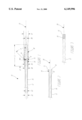
- FIG. 1 is a side view of a tip and tubing assembly embodying the present invention
- FIG. 2 is a cross-section of the tubing with a protruding member
- FIG. 3 is a side view of the tubing illustrating without a protruding member and with an area of surface treatment.
- FIG. 1 illustrating the molded tip 30 disposed on tubing 12 forming an assembly 10.
- the molded tip 30 on tubing 12 advantageously eliminates adhesives and provides a generally superior mechanical bond between the components 12, 30.
- the molded tip 30 is formed in a cavity of a mold which supports the distal end 18 of the tubing 12.
- the molded tip 30 is preferably made of a thermoplastic or polymeric material having a lower melting temperature than the portion of the tubing 12 that is placed in the cavity of the mold. It is envisioned that the tubing 12 may be made of different materials having different melting temperatures, however, the tubing is preferably made of one material.
- the distal portion 18 of the tubing 12 is placed in the mold and supported by the mold and the liquid molded tip material is injected or disposed into the cavity.
- the liquid molded tip cools to a solid molded tip material
- the tubing and tip assembly 10 is removed from the mold.
- the cavity has a preformed shape slightly larger than the desired molded tip 30 in order to account for shrinkage and for removal of the tip 30 from the mold.
- a preferred shape of the molded tip 30 on tubing 12 is illustrated in FIG. 1, although any number of mold shapes may be used to form the molded tip and tubing assembly 10.
- the molded tip and tubing assembly 10 may be used in delivery devices and catheters ranging in size from about 3 French to about 34 French, although, smaller and larger sizes are also envisioned.
- the length of the tubing 12 can be most any length depending on the treatment and use. Table 1 below describes preferred ranges of dimensions for about 3 French to about 14 French size devices incorporating the molded tip on tubing assembly 10. Devices outside the ranges described are also envisioned.
- the tubing 12 at the distal portion 18 may have a member 14 which is flared in a radially outward direction to provide a locking mechanism in the molded tip 30 to prevent longitudinal movement of molded tip 30 off the tubing 12.
- the angle A of the member 14 extending from the longitudinal axis 20 of the tubing 12 may range from about 0° to about 210° measured from the longitudinal axis of the tubing, and is preferably in the range of about 45° to about 135°.
- the length of the surface treatment L3 is preferably at least the length of L2 corresponding to the amount of tubing disposed under the molded tip 30.
- the member 14 or distal end 15 of the tubing 12 is positioned at a predetermined longitudinal position in the molded tip 30.
- the tubing 12 and molded tip 30 may have a lumen 16 extending therethrough.
- the molded tip 30 may have an equal, larger, or smaller size diameter lumen 16 than the lumen 16 of the tubing 12.
- FIG. 2 illustrates a cross-section of the tubing 12 with a protruding roll over member 14 at the distal portion 18.
- the tubing 12 preferably has surface treatment 19 over a portion L3 to be disposed under the molded tip 30.
- the surface treatment is further illustrated in FIG. 3 and described in greater detail below.
- the surface treatment 19 may extend over member 14 as well to promote a stronger mechanical bond.
- FIG. 3 illustrates tubing 12 without a protruding roll over member 14 and illustrates surface treatment 19 over a portion L3 on the outside surface at the distal portion 18.
- surface treatment 19 may further include providing a coarse surface, an attached member, ridges, notches, grooves, or holes for generally greater surface area for the liquid resin material to form about for a stronger mechanical bond.
- surface irregularities measured from an untreated surface are generally no larger in size than the thickness of the wall of the tubing.
- surface irregularities (peaks and valleys) such as knurling and surface texture are no greater than a maximum of about 10% of the tubing 12 wall thickness.
- the molded tip and tubing assembly may be constructed using a number of methods and materials, in a wide variety of sizes and styles for the greater efficiency and convenience of a user.
Abstract
Description
              TABLE 1
______________________________________
Dimension       Range
______________________________________
D1              1 mm to 4.7 mm
D2              .51 mm to 1.32 mm
D3              .25 mm to .99 mm
D4              .81 mm to 4.22 mm
D5              .78 mm to 4.31 mm
D6              .25 mm to .99 mm
L1              3 mm to 5 mm
L2              3 mm to 5 mm
L3              3 mm to 5 mm
Radius R        .25 mm to .30 mm
Angle A         0 degrees to 210 degrees
______________________________________
Claims (18)
Priority Applications (5)
| Application Number | Priority Date | Filing Date | Title |
|---|---|---|---|
| US09/007,867 US6149996A (en) | 1998-01-15 | 1998-01-15 | Molded tip and tubing and method of making same |
| CA002315754A CA2315754C (en) | 1998-01-15 | 1999-01-08 | Molded tip and tubing and method of making same |
| PCT/IB1999/000127 WO1999036119A1 (en) | 1998-01-15 | 1999-01-08 | Molded tip and tubing and method of making same |
| EP99900586A EP1047470A1 (en) | 1998-01-15 | 1999-01-08 | Molded tip and tubing and method of making same |
| JP2000539888A JP2002509006A (en) | 1998-01-15 | 1999-01-08 | Molded tips and tubes and methods for their manufacture |
Applications Claiming Priority (1)
| Application Number | Priority Date | Filing Date | Title |
|---|---|---|---|
| US09/007,867 US6149996A (en) | 1998-01-15 | 1998-01-15 | Molded tip and tubing and method of making same |
Publications (1)
| Publication Number | Publication Date |
|---|---|
| US6149996A true US6149996A (en) | 2000-11-21 |
Family
ID=21728523
Family Applications (1)
| Application Number | Title | Priority Date | Filing Date |
|---|---|---|---|
| US09/007,867 Expired - Lifetime US6149996A (en) | 1998-01-15 | 1998-01-15 | Molded tip and tubing and method of making same |
Country Status (5)
| Country | Link |
|---|---|
| US (1) | US6149996A (en) |
| EP (1) | EP1047470A1 (en) |
| JP (1) | JP2002509006A (en) |
| CA (1) | CA2315754C (en) |
| WO (1) | WO1999036119A1 (en) |
Cited By (25)
| Publication number | Priority date | Publication date | Assignee | Title |
|---|---|---|---|---|
| US20030018293A1 (en) * | 2001-06-29 | 2003-01-23 | Allan Tanghoj | Catheter device |
| US20030060807A1 (en) * | 2001-09-24 | 2003-03-27 | Allan Tanghoj | Urinary catheter assembly allowing for non-contaminated insertion of the catheter into a urinary canal |
| US20040140585A1 (en) * | 2003-01-17 | 2004-07-22 | Scimed Life Systems, Inc. | Methods of forming catheters with soft distal tips |
| US20040158231A1 (en) * | 2001-06-29 | 2004-08-12 | Allan Tanghoj | Catheter device |
| US20040163980A1 (en) * | 2001-06-29 | 2004-08-26 | Allan Tanghoj | Catheter assembly valve system |
| EP1457775A1 (en) * | 2003-03-10 | 2004-09-15 | Möller Feinmechanik GmbH & Co. | Hose made of high temperature resistant plastic material, method of forming the end of such a hose |
| US20040204749A1 (en) * | 2003-04-11 | 2004-10-14 | Richard Gunderson | Stent delivery system with securement and deployment accuracy |
| US20040267346A1 (en) * | 2003-06-30 | 2004-12-30 | Shelso Susan I. | Stent grip and system for use therewith |
| US6893427B1 (en) * | 2000-03-23 | 2005-05-17 | Vascon, Llc | Catheter with thermoresponsive distal tip portion |
| US20050171591A1 (en) * | 2004-01-29 | 2005-08-04 | Scimed Life Systems, Inc. | Catherter tip |
| US20070257462A1 (en) * | 2006-05-02 | 2007-11-08 | Meritor Suspension Systems Company, Us | Die cast stabilizer bar ends |
| CN101585223A (en) * | 2001-06-29 | 2009-11-25 | 科洛普拉斯特公司 | Be used to make the method and the conduit of conduit |
| US20100049084A1 (en) * | 2008-08-22 | 2010-02-25 | Nock Andrew P | Biopsy marker delivery device |
| US20100049085A1 (en) * | 2008-08-22 | 2010-02-25 | Nock Andrew P | Method of making a biopsy marker delivery device |
| US7815599B2 (en) | 2004-12-10 | 2010-10-19 | Boston Scientific Scimed, Inc. | Catheter having an ultra soft tip and methods for making the same |
| US8006594B2 (en) * | 2008-08-11 | 2011-08-30 | Cardiac Dimensions, Inc. | Catheter cutting tool |
| WO2012116753A1 (en) | 2011-03-03 | 2012-09-07 | Agilent Technologies, Inc. | Coated capillary with remelted coating for front sided sealing |
| US20120239061A1 (en) * | 2011-03-15 | 2012-09-20 | Mathur Sandip V | Endoscopic full thickness gastric reduction apparatus and method |
| US9066826B2 (en) | 2004-04-09 | 2015-06-30 | Boston Scientific Scimed, Inc. | Medical device delivery systems |
| US20160088973A1 (en) * | 2014-09-30 | 2016-03-31 | Sodastream Industries Ltd. | Carbonation tube |
| US9585784B2 (en) | 2011-08-29 | 2017-03-07 | Coloplast A/S | Catheter activation by handle removal |
| US20170224965A1 (en) * | 2016-02-10 | 2017-08-10 | Terumo Kabushiki Kaisha | Medical elongated body and balloon catheter |
| US10076435B2 (en) | 2015-02-25 | 2018-09-18 | Cook Medical Technologies Llc | Stent deployment system with overmolded tip |
| EP3685872A1 (en) | 2019-01-22 | 2020-07-29 | Dentsply IH AB | Urinary catheter having an injection molded tip |
| US20210077774A1 (en) * | 2018-06-14 | 2021-03-18 | Cardiacassist, Inc. | Dual lumen cannula with flexible distal end |
Families Citing this family (8)
| Publication number | Priority date | Publication date | Assignee | Title |
|---|---|---|---|---|
| DE10012852A1 (en) * | 2000-03-16 | 2001-09-20 | Angiomed Ag | Percutaneous transluminal stent delivery system, has distal tip zone which is contiguous with distal end of tube, in which tip zone both luminal surface and abluminal surface taper radially inwardly nearer to distal end of tube |
| DE19954330C2 (en) * | 1999-11-11 | 2002-12-05 | Angiomed Ag | Stent delivery system for delivery of flexible stents |
| US7758624B2 (en) | 2000-11-13 | 2010-07-20 | C. R. Bard, Inc. | Implant delivery device |
| JP4501337B2 (en) * | 2002-11-01 | 2010-07-14 | 株式会社カネカ | catheter |
| DE602004028421D1 (en) * | 2004-05-05 | 2010-09-09 | Invatec Spa | Method of making a catheter tip |
| GB2441776A (en) * | 2006-09-15 | 2008-03-19 | Novagen Ltd | Atraumatic tip |
| EP2606919A1 (en) * | 2011-12-22 | 2013-06-26 | ECP Entwicklungsgesellschaft mbH | Sluice device for inserting a catheter |
| EP3831436A1 (en) * | 2012-08-01 | 2021-06-09 | Boston Scientific Scimed Inc. | Guide extension catheters and methods for manufacturing the same |
Citations (15)
| Publication number | Priority date | Publication date | Assignee | Title |
|---|---|---|---|---|
| US4385635A (en) * | 1980-04-25 | 1983-05-31 | Ruiz Oscar F | Angiographic catheter with soft tip end |
| US4531943A (en) * | 1983-08-08 | 1985-07-30 | Angiomedics Corporation | Catheter with soft deformable tip |
| US4551292A (en) * | 1984-04-05 | 1985-11-05 | Angiomedics, Inc. | Method for making a catheter with a soft, deformable tip |
| US5009659A (en) * | 1989-10-30 | 1991-04-23 | Schneider (Usa) Inc. | Fiber tip atherectomy catheter |
| US5026377A (en) * | 1989-07-13 | 1991-06-25 | American Medical Systems, Inc. | Stent placement instrument and method |
| US5088991A (en) * | 1988-07-14 | 1992-02-18 | Novoste Corporation | Fuseless soft tip angiographic catheter |
| US5240537A (en) * | 1991-07-01 | 1993-08-31 | Namic U.S.A. Corporation | Method for manufacturing a soft tip catheter |
| US5425712A (en) * | 1993-04-09 | 1995-06-20 | Schneider (Usa) Inc. | Dilatation catheter having soft bumper tip |
| US5484444A (en) * | 1992-10-31 | 1996-01-16 | Schneider (Europe) A.G. | Device for the implantation of self-expanding endoprostheses |
| US5509910A (en) * | 1994-05-02 | 1996-04-23 | Medtronic, Inc. | Method of soft tip attachment for thin walled catheters |
| US5591172A (en) * | 1991-06-14 | 1997-01-07 | Ams Medinvent S.A. | Transluminal implantation device |
| US5628755A (en) * | 1995-02-20 | 1997-05-13 | Schneider (Europe) A.G. | Balloon catheter and stent delivery system |
| US5653684A (en) * | 1992-06-26 | 1997-08-05 | Schneider (Usa), Inc. | Catheter with expandable wire mesh tip |
| US5662703A (en) * | 1995-04-14 | 1997-09-02 | Schneider (Usa) Inc. | Rolling membrane stent delivery device |
| US5891110A (en) * | 1997-10-15 | 1999-04-06 | Scimed Life Systems, Inc. | Over-the-wire catheter with improved trackability |
Family Cites Families (2)
| Publication number | Priority date | Publication date | Assignee | Title |
|---|---|---|---|---|
| US5401257A (en) * | 1993-04-27 | 1995-03-28 | Boston Scientific Corporation | Ureteral stents, drainage tubes and the like |
| WO1996020750A1 (en) * | 1995-01-04 | 1996-07-11 | Medtronic, Inc. | Improved method of soft tip forming |
-
1998
- 1998-01-15 US US09/007,867 patent/US6149996A/en not_active Expired - Lifetime
-
1999
- 1999-01-08 JP JP2000539888A patent/JP2002509006A/en active Pending
- 1999-01-08 WO PCT/IB1999/000127 patent/WO1999036119A1/en not_active Application Discontinuation
- 1999-01-08 CA CA002315754A patent/CA2315754C/en not_active Expired - Fee Related
- 1999-01-08 EP EP99900586A patent/EP1047470A1/en not_active Withdrawn
Patent Citations (15)
| Publication number | Priority date | Publication date | Assignee | Title |
|---|---|---|---|---|
| US4385635A (en) * | 1980-04-25 | 1983-05-31 | Ruiz Oscar F | Angiographic catheter with soft tip end |
| US4531943A (en) * | 1983-08-08 | 1985-07-30 | Angiomedics Corporation | Catheter with soft deformable tip |
| US4551292A (en) * | 1984-04-05 | 1985-11-05 | Angiomedics, Inc. | Method for making a catheter with a soft, deformable tip |
| US5088991A (en) * | 1988-07-14 | 1992-02-18 | Novoste Corporation | Fuseless soft tip angiographic catheter |
| US5026377A (en) * | 1989-07-13 | 1991-06-25 | American Medical Systems, Inc. | Stent placement instrument and method |
| US5009659A (en) * | 1989-10-30 | 1991-04-23 | Schneider (Usa) Inc. | Fiber tip atherectomy catheter |
| US5591172A (en) * | 1991-06-14 | 1997-01-07 | Ams Medinvent S.A. | Transluminal implantation device |
| US5240537A (en) * | 1991-07-01 | 1993-08-31 | Namic U.S.A. Corporation | Method for manufacturing a soft tip catheter |
| US5653684A (en) * | 1992-06-26 | 1997-08-05 | Schneider (Usa), Inc. | Catheter with expandable wire mesh tip |
| US5484444A (en) * | 1992-10-31 | 1996-01-16 | Schneider (Europe) A.G. | Device for the implantation of self-expanding endoprostheses |
| US5425712A (en) * | 1993-04-09 | 1995-06-20 | Schneider (Usa) Inc. | Dilatation catheter having soft bumper tip |
| US5509910A (en) * | 1994-05-02 | 1996-04-23 | Medtronic, Inc. | Method of soft tip attachment for thin walled catheters |
| US5628755A (en) * | 1995-02-20 | 1997-05-13 | Schneider (Europe) A.G. | Balloon catheter and stent delivery system |
| US5662703A (en) * | 1995-04-14 | 1997-09-02 | Schneider (Usa) Inc. | Rolling membrane stent delivery device |
| US5891110A (en) * | 1997-10-15 | 1999-04-06 | Scimed Life Systems, Inc. | Over-the-wire catheter with improved trackability |
Non-Patent Citations (3)
| Title |
|---|
| PEBA Polyether Block Amide, Atochem, Dec. 1987. * |
| Wallstent Esophageal II Endoprosthesis brochure (481765 0197) received by Schneider (USA) Inc from printing company on Jan. 16, 1997 and provided to National Sales Force the week of Jan. 27, 1997; and A commercially available stent delivery device (Esophageal II) sold by Schneider (USA) Inc has tubing including an inner and outer jacket made of materials including polyurethane 55D (Pellethane 55D), Barium Sulfate, Titanium Dioxide, Carbon Black, and Isoplast 2510, and has an intemediate wire braid layer. A tip is molded on the end of the tubing The molded tip is made of Tecoflex which is a polyether based thermoplastic, aliphatic polyurethane. The tip and tubing are radiopaque. The Esophageal II device is about 18 French size. * |
| Wallstent® Esophageal II Endoprosthesis brochure (481765-0197) received by Schneider (USA) Inc from printing company on Jan. 16, 1997 and provided to National Sales Force the week of Jan. 27, 1997; and A commercially available stent delivery device (Esophageal II) sold by Schneider (USA) Inc has tubing including an inner and outer jacket made of materials including polyurethane 55D (Pellethane 55D), Barium Sulfate, Titanium Dioxide, Carbon Black, and Isoplast 2510, and has an intemediate wire braid layer. A tip is molded on the end of the tubing The molded tip is made of Tecoflex which is a polyether-based thermoplastic, aliphatic polyurethane. The tip and tubing are radiopaque. The Esophageal II device is about 18 French size. |
Cited By (59)
| Publication number | Priority date | Publication date | Assignee | Title |
|---|---|---|---|---|
| US6893427B1 (en) * | 2000-03-23 | 2005-05-17 | Vascon, Llc | Catheter with thermoresponsive distal tip portion |
| EP1420845B2 (en) † | 2001-06-29 | 2015-12-09 | Coloplast A/S | A method of producing a catheter and a catheter |
| US7517343B2 (en) | 2001-06-29 | 2009-04-14 | Coloplast A/S | Catheter assembly |
| US10441454B2 (en) | 2001-06-29 | 2019-10-15 | Coloplast A/S | Urinary catheter provided as a package |
| US20040163980A1 (en) * | 2001-06-29 | 2004-08-26 | Allan Tanghoj | Catheter assembly valve system |
| US20030018293A1 (en) * | 2001-06-29 | 2003-01-23 | Allan Tanghoj | Catheter device |
| US8986286B2 (en) | 2001-06-29 | 2015-03-24 | Coloplast A/S | Catheter device |
| US20040254562A1 (en) * | 2001-06-29 | 2004-12-16 | Allan Tanghoj | Method of producing a catheter and a catheter |
| US8679092B2 (en) | 2001-06-29 | 2014-03-25 | Coloplast A/S | Catheter assembly |
| US8066693B2 (en) | 2001-06-29 | 2011-11-29 | Coloplast A/S | Catheter device |
| US7682353B2 (en) | 2001-06-29 | 2010-03-23 | Coloplast A/S | Catheter device |
| US20040158231A1 (en) * | 2001-06-29 | 2004-08-12 | Allan Tanghoj | Catheter device |
| US20100204682A1 (en) * | 2001-06-29 | 2010-08-12 | Coloplast A/S | Catheter device |
| AU2002320957B2 (en) * | 2001-06-29 | 2008-01-10 | Coloplast A/S | A method of producing a catheter and a catheter |
| US20110213343A1 (en) * | 2001-06-29 | 2011-09-01 | Coloplast A/S | Catheter assembly |
| US20080027414A1 (en) * | 2001-06-29 | 2008-01-31 | Coloplast A/S | Method of producing a catheter and a catheter |
| CN101585223A (en) * | 2001-06-29 | 2009-11-25 | 科洛普拉斯特公司 | Be used to make the method and the conduit of conduit |
| CN100522279C (en) * | 2001-06-29 | 2009-08-05 | 科洛普拉斯特公司 | A method of producing a catheter and a catheter |
| US20080319423A1 (en) * | 2001-09-24 | 2008-12-25 | Coloplast A/S (Reel 012442, Frame 0712) | Urinary catheter assembly allowing for non-contaminated insertion of the catheter into a urinary canal |
| US7311698B2 (en) | 2001-09-24 | 2007-12-25 | Coloplast A/S | Urinary catheter assembly allowing for non-contaminated insertion of the catheter into a urinary canal |
| US20030060807A1 (en) * | 2001-09-24 | 2003-03-27 | Allan Tanghoj | Urinary catheter assembly allowing for non-contaminated insertion of the catheter into a urinary canal |
| US7922712B2 (en) | 2001-09-24 | 2011-04-12 | Coloplast A/S | Urinary catheter assembly allowing for non-contaminated insertion of the catheter into a urinary canal |
| US20040140585A1 (en) * | 2003-01-17 | 2004-07-22 | Scimed Life Systems, Inc. | Methods of forming catheters with soft distal tips |
| US7322988B2 (en) | 2003-01-17 | 2008-01-29 | Boston Scientific Scimed, Inc. | Methods of forming catheters with soft distal tips |
| EP1457775A1 (en) * | 2003-03-10 | 2004-09-15 | Möller Feinmechanik GmbH & Co. | Hose made of high temperature resistant plastic material, method of forming the end of such a hose |
| US20040204749A1 (en) * | 2003-04-11 | 2004-10-14 | Richard Gunderson | Stent delivery system with securement and deployment accuracy |
| US7473271B2 (en) | 2003-04-11 | 2009-01-06 | Boston Scientific Scimed, Inc. | Stent delivery system with securement and deployment accuracy |
| US20040267346A1 (en) * | 2003-06-30 | 2004-12-30 | Shelso Susan I. | Stent grip and system for use therewith |
| US20090105803A1 (en) * | 2003-06-30 | 2009-04-23 | Boston Scientific Scimed, Inc. | Stent grip and systems for use therewith |
| US7470282B2 (en) * | 2003-06-30 | 2008-12-30 | Boston Scientific Scimed, Inc. | Stent grip and system for use therewith |
| US8172891B2 (en) | 2003-06-30 | 2012-05-08 | Boston Scientific Scimed, Inc. | Stent grip and systems for use therewith |
| US20050171591A1 (en) * | 2004-01-29 | 2005-08-04 | Scimed Life Systems, Inc. | Catherter tip |
| US7972350B2 (en) | 2004-01-29 | 2011-07-05 | Boston Scientific Scimed, Inc. | Catheter tip |
| US9066826B2 (en) | 2004-04-09 | 2015-06-30 | Boston Scientific Scimed, Inc. | Medical device delivery systems |
| US9737427B2 (en) | 2004-04-09 | 2017-08-22 | Boston Scientific Scimed, Inc. | Medical device delivery systems |
| US7815599B2 (en) | 2004-12-10 | 2010-10-19 | Boston Scientific Scimed, Inc. | Catheter having an ultra soft tip and methods for making the same |
| US8973239B2 (en) | 2004-12-10 | 2015-03-10 | Boston Scientific Scimed, Inc. | Catheter having an ultra soft tip and methods for making the same |
| US20070257462A1 (en) * | 2006-05-02 | 2007-11-08 | Meritor Suspension Systems Company, Us | Die cast stabilizer bar ends |
| US8250960B2 (en) * | 2008-08-11 | 2012-08-28 | Cardiac Dimensions, Inc. | Catheter cutting tool |
| US20110308367A1 (en) * | 2008-08-11 | 2011-12-22 | Hayner Louis R | Catheter Cutting Tool |
| US8006594B2 (en) * | 2008-08-11 | 2011-08-30 | Cardiac Dimensions, Inc. | Catheter cutting tool |
| US8532747B2 (en) | 2008-08-22 | 2013-09-10 | Devicor Medical Products, Inc. | Biopsy marker delivery device |
| US20100049084A1 (en) * | 2008-08-22 | 2010-02-25 | Nock Andrew P | Biopsy marker delivery device |
| US20100049085A1 (en) * | 2008-08-22 | 2010-02-25 | Nock Andrew P | Method of making a biopsy marker delivery device |
| WO2012116753A1 (en) | 2011-03-03 | 2012-09-07 | Agilent Technologies, Inc. | Coated capillary with remelted coating for front sided sealing |
| US9962695B2 (en) | 2011-03-03 | 2018-05-08 | Agilent Technologies, Inc. | Coated capillary with remelted coating for front sided sealing |
| US20120239061A1 (en) * | 2011-03-15 | 2012-09-20 | Mathur Sandip V | Endoscopic full thickness gastric reduction apparatus and method |
| US9585784B2 (en) | 2011-08-29 | 2017-03-07 | Coloplast A/S | Catheter activation by handle removal |
| US9854935B2 (en) * | 2014-09-30 | 2018-01-02 | Sodastream Industries Ltd. | Carbonation tube |
| US20160088973A1 (en) * | 2014-09-30 | 2016-03-31 | Sodastream Industries Ltd. | Carbonation tube |
| US10076435B2 (en) | 2015-02-25 | 2018-09-18 | Cook Medical Technologies Llc | Stent deployment system with overmolded tip |
| US10716693B2 (en) | 2015-02-25 | 2020-07-21 | Cook Medical Technologies Llc | Stent deployment system with overmolded tip |
| US10806618B2 (en) | 2015-02-25 | 2020-10-20 | Cook Medical Technologies Llc | Stent deployment system with overmolded tip |
| US20170224965A1 (en) * | 2016-02-10 | 2017-08-10 | Terumo Kabushiki Kaisha | Medical elongated body and balloon catheter |
| US10617852B2 (en) * | 2016-02-10 | 2020-04-14 | Terumo Kabushiki Kaisha | Medical elongated body and balloon catheter |
| US20210077774A1 (en) * | 2018-06-14 | 2021-03-18 | Cardiacassist, Inc. | Dual lumen cannula with flexible distal end |
| EP3685872A1 (en) | 2019-01-22 | 2020-07-29 | Dentsply IH AB | Urinary catheter having an injection molded tip |
| WO2020151958A1 (en) | 2019-01-22 | 2020-07-30 | Dentsply Ih Ab | Urinary catheter having an injection molded tip |
| EP4324616A2 (en) | 2019-01-22 | 2024-02-21 | Wellspect AB | A method of manufacuring a urinary catheter having an injection molded tip and the urinary catheter |
Also Published As
| Publication number | Publication date |
|---|---|
| WO1999036119A1 (en) | 1999-07-22 |
| EP1047470A1 (en) | 2000-11-02 |
| CA2315754C (en) | 2008-05-27 |
| CA2315754A1 (en) | 1999-07-22 |
| JP2002509006A (en) | 2002-03-26 |
Similar Documents
| Publication | Publication Date | Title |
|---|---|---|
| US6149996A (en) | Molded tip and tubing and method of making same | |
| US11786709B2 (en) | Expandable medical devices | |
| US6783542B2 (en) | Crimpable balloon/stent protector | |
| US6068622A (en) | Single piece hub/strain relief that can be injection molded over a shaft | |
| US6001117A (en) | Bellows medical construct and apparatus and method for using same | |
| US4874373A (en) | Dip formed catheter and assembly | |
| US6245053B1 (en) | Soft tip guiding catheter and method of fabrication | |
| US6733520B2 (en) | Sandwich striped sleeve for stent delivery | |
| US6296633B1 (en) | Medical device tubing assembly and method of making the same | |
| WO2002083223A1 (en) | A catheter | |
| EP0906134A1 (en) | Low profile valve and method of making | |
| US20090254113A1 (en) | Dilatation balloon with ridges and methods | |
| US7718106B2 (en) | Medical devices and related systems and methods | |
| US20090054872A1 (en) | Endovascular Device Tip Assembly | |
| US7448122B1 (en) | Method of compressing a polymeric layer of an expandable medical device | |
| AU2015255298B2 (en) | Expandable medical devices | |
| US20090163946A1 (en) | Catheter | |
| IE20020280A1 (en) | A catheter |
Legal Events
| Date | Code | Title | Description |
|---|---|---|---|
| AS | Assignment |
Owner name: SCHNEIDER (USA) INC., MINNESOTA Free format text: ASSIGNMENT OF ASSIGNORS INTEREST;ASSIGNORS:HELGERSON, JEFFREY A.;FIEDLER, GARY R.;REEL/FRAME:008934/0795 Effective date: 19980113 |
|
| STCF | Information on status: patent grant |
Free format text: PATENTED CASE |
|
| FPAY | Fee payment |
Year of fee payment: 4 |
|
| AS | Assignment |
Owner name: SCIMED LIFE SYSTEMS, INC., MINNESOTA Free format text: MERGER;ASSIGNOR:BOSTON SCIENTIFIC SCIMED, INC.;REEL/FRAME:018454/0834 Effective date: 20050101 Owner name: BOSTON SCIENTIFIC SCIMED, INC., MINNESOTA Free format text: CHANGE OF NAME;ASSIGNOR:SCHNEIDER (USA) INC.;REEL/FRAME:018454/0858 Effective date: 19990427 Owner name: BOSTON SCIENTIFIC SCIMED, INC., MINNESOTA Free format text: CHANGE OF NAME;ASSIGNOR:SCIMED LIFE SYSTEMS, INC.;REEL/FRAME:018454/0866 Effective date: 20050101 |
|
| FPAY | Fee payment |
Year of fee payment: 8 |
|
| FPAY | Fee payment |
Year of fee payment: 12 |