US6150776A - Variable frequency motor starting system and method - Google Patents
Variable frequency motor starting system and method Download PDFInfo
- Publication number
- US6150776A US6150776A US09/304,757 US30475799A US6150776A US 6150776 A US6150776 A US 6150776A US 30475799 A US30475799 A US 30475799A US 6150776 A US6150776 A US 6150776A
- Authority
- US
- United States
- Prior art keywords
- frequency
- value
- motor
- starting
- varying voltage
- Prior art date
- Legal status (The legal status is an assumption and is not a legal conclusion. Google has not performed a legal analysis and makes no representation as to the accuracy of the status listed.)
- Expired - Lifetime
Links
Images
Classifications
-
- H—ELECTRICITY
- H02—GENERATION; CONVERSION OR DISTRIBUTION OF ELECTRIC POWER
- H02P—CONTROL OR REGULATION OF ELECTRIC MOTORS, ELECTRIC GENERATORS OR DYNAMO-ELECTRIC CONVERTERS; CONTROLLING TRANSFORMERS, REACTORS OR CHOKE COILS
- H02P1/00—Arrangements for starting electric motors or dynamo-electric converters
- H02P1/16—Arrangements for starting electric motors or dynamo-electric converters for starting dynamo-electric motors or dynamo-electric converters
- H02P1/26—Arrangements for starting electric motors or dynamo-electric converters for starting dynamo-electric motors or dynamo-electric converters for starting an individual polyphase induction motor
- H02P1/30—Arrangements for starting electric motors or dynamo-electric converters for starting dynamo-electric motors or dynamo-electric converters for starting an individual polyphase induction motor by progressive increase of frequency of supply to primary circuit of motor
Definitions
- the invention pertains to a system and method for starting an AC motor. More specifically, the invention pertains to adjusting the frequency of the power signal applied to the AC motor.
- the electric motor When power is initially applied to an electric motor, and the motor begins to accelerate from rest, the electric motor must overcome several boundaries, one of which includes an initial inertia. Furthermore during the starting cycle or the time during which the motor accelerates up to its operating speed, also known as run up, the torque developed by the motor at any given instant needs to exceed the torque required by the load at that speed. If the torque developed by the motor fails to exceed the torque required by the load, the load will begin to decelerate and the motor may eventually stall.
- the accelerating torque At any given speed during run up, the difference between the motor torque and the load torque is known as the accelerating torque.
- a positive accelerating torque will result in the speed of the motor increasing to its operating speed.
- the accelerating torque in combination with the load moment of inertia determines the run up time.
- a variable frequency motor starting system incorporates a variable frequency AC power supply for generating an AC power output signal.
- a controller coupled to the variable frequency AC power supply, produces a control signal for adjusting the frequency of the AC power output signal generated by the supply.
- the controller adjusts the frequency from a first value to a second value, wherein the second value is below the typical operating frequency.
- the controller then adjusts the frequency by increasing it from the second value to a final value.
- a detector detects the application of AC power to the AC motor.
- the controller adjusts the frequency of the AC power output signal in response thereto.
- the controller after adjusting the value of the frequency of the AC power output signal to a final value, the controller will maintain the value of the frequency at the final value, unless the motor is subsequently stopped and needs to be restarted.
- the system receives power from a DC power source, which may include one or more batteries.
- a method of starting an AC motor incorporates the steps of applying a varying voltage to an AC motor, wherein the nominal frequency of the applied voltage is adjusted.
- the frequency of the varying voltage is initially adjusted from a first value to a second value, which is below the typical operating frequency of the applied voltage. Then the frequency of the varying voltage is selectively increased from the second value to its final value.
- FIG. 1 is a block diagram of a variable frequency motor starting system in accordance with the present invention
- FIG. 2 is a more detailed block diagram of one aspect of the variable frequency motor starting system of FIG. 1;
- FIG. 3 is a graph depicting an example of frequency as a function of time of the AC power output signal generated by the variable frequency motor starting systems of FIGS. 1 or 2;
- FIG. 4 is a further more detailed block diagram of one aspect of the variable frequency motor starting system of FIG. 1;
- FIG. 5 is a flow diagram of a method of starting an AC motor for use with the systems of FIGS. 1, 2 or 4;
- FIGS. 6A and 6B are more detailed flow diagrams, which together illustrate a method of starting an AC motor for use with the system of FIG. 4.
- the operational speed of an induction motor is equivalent to the synchronous speed less the slip which increases with applied load torque and friction.
- "Synchronous speed” is the speed the motor would obtain if the rotor of the motor rotated in synchrony with the magnetic field. Frictional losses include friction in the bearings, air resistance within the motor, and additional drag imposed by the load. In an induction motor, the amount the rotor lags behind the rotational speed of the magnetic field is known as "slip".
- the frequency of the AC line supplying power to the motor can be set at or ramped to a frequency below the typical AC line frequency. As the frequency is adjusted to a frequency below the typical AC line frequency, the surge current is decreased and the starting torque is increased.
- the frequency of the AC line is increased or ramped up, so as to bring the motor up to its ideal operating frequency.
- the ideal operating frequency is the typical operating frequency.
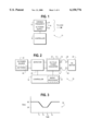
- FIG. 1 illustrates a block diagram of a variable frequency starting system 10 which embodies the teachings of the present invention.
- the system 10 includes a variable frequency AC power supply 12, which includes power output terminal(s) 14 adapted for applying the AC power output signal to a load, like an AC motor.
- the system 10 further includes a controller 16 coupled to the variable frequency AC power supply 12. The controller 16 produces a control signal for adjusting the frequency of the AC power output signal generated by the variable frequency AC power supply 12.
- FIG. 2 illustrates a more detailed block diagram of a variable frequency starting system 18, according to one aspect of the variable frequency motor starting system 10 of FIG. 1.
- the system 18 includes a variable frequency AC power supply 12, including a DC-to-AC power converter 20.
- the DC-to-AC power converter 20 is coupled to a DC power source 22 via a detector 24.
- the power supply generates an AC power output signal at power output terminal(s) 14.
- the output terminals are adapted for coupling the generated AC power output signal to a load, like an AC motor 26 via corresponding input terminals 28.
- the DC power source can be provided by one or more batteries 30, which may be rechargeable.
- batteries 30, which may be rechargeable Other variable frequency supplies are within the spirit and scope of the present invention.
- the system 18 further includes a controller 16, coupled to the DC-to-AC power converter 20 for producing a control signal for adjusting the frequency of the AC power output signal.
- the controller 16 can be implemented using programmable or hardwired logic arrays, read only or random access memories, and/or microprocessors.
- the controller 16 includes a microprocessor 32, illustrated in FIG. 2 with dashed lines.
- the controller of the preferred embodiment further includes a corresponding control program. Instructions for the program are stored in a memory, separate from or as part of the microprocessor 32.
- the controller 16 is coupled to the detector 24.
- the detector 24 detects the need to start an AC motor 26 coupled to the power output terminal(s) 14 and provides a corresponding indication to the controller 16.
- the controller 16 receives the indication from the detector 24, the controller produces a control signal for adjusting the frequency of the power output signal generated by the DC-to-AC power converter 20.
- Detector 24 can also be located at the output side of output terminal(s) 14.
- the detector monitors the signal characteristics of the power supplied to the DC-to-AC power converter 20 from the DC power source 22.
- the signal characteristics of the power supplied to the DC-to-AC power converter 20 are proportional to signal characteristics of the power supplied to the load coupled to the power output terminal(s) 14.
- the detector 24 monitors the signal characteristics and when the large surge current is detected, the detector 24 provides an indication to the controller 16.
- the detector 24 may be coupled so as to monitor the signal at either of the two points.
- a detector could monitor for an external stimulus, which alternatively identifies the start of an AC motor 26. For example, a signal identifying the presence of water may be detected, which triggers the start of a pump motor.
- the controller 16 When power is initially supplied to a load, for starting the AC motor 26, the controller 16 adjusts the frequency of the AC power output signal from a first value to a second value, which is below the typical operating frequency. When the motor 26 reaches a speed at or near the synchronous speed for an applied voltage having a frequency with the second value, the controller 16 selectively increases the frequency of the power output signal generated by the variable frequency AC power supply 12 to a final value.
- FIG. 3 An example of frequency as a function of time of the AC power output signal generated by the variable frequency motor starting systems is illustrated by graph 34 in FIG. 3.
- the AC power output signal has a frequency of 60 Hz, which corresponds to a typical line frequency of power supplied by the local utility in many jurisdictions and a typical operating frequency for the AC motor 26.
- alternative starting frequencies could be used including a frequency of zero, which may indicate no power being initially supplied at the power output terminal(s) 14 of the variable frequency AC power supply 12.
- the frequency of the AC power output signal is adjusted from a first value to a second value, which is below the typical operating frequency.
- this transition is illustrated during time period from t 1 to t 2 , when the first frequency of 60 Hz at time t 1 is adjusted to a second frequency of 28 Hz through time t 2 .
- the starting current of the AC motor decreases and the starting torque increases.
- the frequency is maintained at 28 Hz, for a period of time from t 2 to t 3 before the frequency of the AC power output signal is selectively increased from the second value to a final value. In many instances this will enable the AC motor 26 to approach a synchronous speed corresponding to the second frequency. In other embodiments this time period may be longer or shorter, or may even be eliminated.
- the frequency of the AC power output signal is then selectively increased from a second value to a final value.
- this transition is illustrated during time period from t 3 to t 4 , when the frequency having a second value of 28 Hz is selectively increased to a final value of 60 Hz.
- the final value at t 4 of 60 Hz corresponds to the first value which also has a value of 60 Hz.
- the transition of the frequency from a first value to a second value and from a second value to a final value will occur in a controlled ramp down or ramp up.
- the transitions of the value of the frequency from t 1 to t 2 and from t 3 to t 4 will be relatively linear, i.e. have a constant slope, as illustrated in graph 34. Nonlinear transitions where the slope varies during the transition are similarly possible. Furthermore, each of the transition times can be longer or shorter.
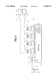
- FIG. 4 illustrates a more detailed block diagram of a variable frequency starting system 36, according to one aspect of the variable frequency motor starting system 10 of FIG. 1.
- the variable frequency starting system 36 includes features of a variable output power supply, which closely corresponds to a low distortion variable output power supply disclosed in Reichard, U.S. Pat. No. 5,508,905, wherein a more specific discussion is provided, the disclosure of which is incorporated herein by reference.
- the starting system 36 provides a plurality of bridge type inverters 38,40,42 and 44, and a plurality of transformers 46, 48, 50 and 52.
- One coil of each of the plurality of transformers 46, 48, 50 and 52 is coupled to a corresponding one of the plurality of inverters 38, 40, 42 and 44.
- the other coil of each of the plurality of transformers 46, 48, 50 and 52 is coupled together in series.
- the inverters 38, 40, 42 and 44 are additionally coupled to a DC power source 22 including one or more batteries 30, via detector 24.
- the system 36 further provides for a controller 54 coupled to the plurality of inverters 38, 40, 42 and 44, for selectively enabling each of the inverters.
- a controller 54 coupled to the plurality of inverters 38, 40, 42 and 44, for selectively enabling each of the inverters.
- the same controller can be used to adjust the frequency of the AC power output signal generated, by varying the rate at which the inverters 38, 40, 42 and 44 are selectively enabled.
- controller 54 can be implemented using programmable or hardwired logic arrays, read only or random access memories, and/or microprocessors.
- controller 54 includes a microprocessor 56 and a corresponding control program. Instructions for the program are stored in a memory, separate from or as part of the microprocessor 56.
- the controller is further coupled to detector 24 for detecting the application of the AC power output signal to AC motor 26 for starting the motor.
- the detector is a resistor 58 coupled in series between the DC power source 22 and the inverters 38, 40, 42 and 44. The current supplied by the DC power source 22 produces a corresponding voltage drop across resistor 58.
- the voltage differential is monitored by the controller 54 to determine when a large surge current is present. In response to the detected surge current, indicative of the start of an AC motor 26, the controller 54 will produce control signal(s) for varying the frequency of the AC power output signal to facilitate the starting of the AC motor 26.
- the pair of signals representing the voltage differential is received by the inputs of an A/D converter incorporated as part of the controller 54.
- the value of resister 58 is selected so as to be small enough to minimize the voltage drop across the resistor, but large enough to provide a sufficient voltage differential to be monitored by the controller 54.
- Managing overall current usage including reducing the starting current for the AC motor extends the ability of existing inverters used in variable output power supplies to start motors which at the normal operating frequency have a starting current requirement which exceeds the current rating of the inverters.
- smaller inverters i.e. inverters rated for lower currents
- the same benefit extends to other components of the variable output power supplies used to generate and/or are exposed to the starting current of the AC motor.
- FIG. 4 illustrates one aspect of the variable frequency motor starting system of the present invention, wherein the variable frequency power supply includes multiple inverters, transformers and a controller
- variable frequency power sources could be used. Examples without limitation include variable frequency power sources using other types of inverter designs with and without the use of transformers, variable frequency drive systems for use with motors, motor generator sets, and other types of variable frequency power sources.
- the present invention could be used for starting other types of motors.
- the present invention could be used to start stepper motors by varying the frequency of the pulses used to turn the motor.
- the envelope of the waveform of the signal applied to the motor could be continuous or discontinuous.
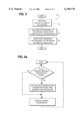
- FIG. 5 illustrates a flow diagram of a method 60 of starting an AC motor for use with the systems of FIGS. 1, 2 or 4.
- the method 60 provides for applying, in step 62, a varying voltage to an AC motor.
- the nominal frequency of the varying voltage is then adjusted, in step 64, from a first value to a second value, which is below the typical operating frequency of the applied voltage.
- the frequency of the applied varying voltage is then selectively increased, in step 66, from the second value to a final value.
- the final value will correspond to the typical operating frequency.
- the typical operating frequency can also correspond to the line frequency of the power signal supplied by the local utility.
- the adjustment or the selective increment of the nominal frequency includes ramping up and/or ramping down the value of the frequency in a controlled fashion. Additionally, adjustment of the value of the nominal frequency may be linear in nature.
- the method prior to the adjusting step 64, performs the step of detecting the need to start an AC motor, which can take the form of detecting a starting current. In yet another embodiment the method further includes, after the increasing step 66, maintaining the applied voltage at the final frequency unless the motor has been stopped and needs to be restarted.
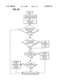
- FIGS. 6A and 6B which together illustrate a more detailed flow diagram of a method of starting an AC motor for use with the systems of FIGS. 1, 2 or 4.
- FIG. 6A illustrates a main programming loop which will operates in absence of an interrupt.
- the main programming loop detects current feedback which is greater than normal, indicative of a motor starting current, and enables the steps within the interrupt routine for adjusting the frequency of the voltage applied to the motor.
- FIG. 6B illustrates the real time interrupt routine, which in addition to performing other interrupt associated tasks includes steps for adjusting and incrementing the frequency of the voltage applied to the motor. While the detailed flow diagram makes reference to incrementing and decrementing the output frequency of the inverter, it will be appreciated that the detailed flow diagram of FIGS. 6A and 6B can be readily adapted to other types of variable frequency sources.
Abstract
A variable frequency motor starting system has a variable frequency AC power supply for generating an AC power output signal applied to an AC motor. A controller is coupled to the variable frequency AC power supply for producing a control signal for adjusting the frequency of the AC power output signal produced. Upon initially applying power to an AC motor or detection of a starting current for an AC motor, the controller adjusts the frequency of the power output signal applied to the AC motor. The frequency of the power output signal is adjusted to a value below the value of the typical operating frequency. The value of the frequency can be increased to the final operating value.
Description
The invention pertains to a system and method for starting an AC motor. More specifically, the invention pertains to adjusting the frequency of the power signal applied to the AC motor.
When power is initially applied to an electric motor, and the motor begins to accelerate from rest, the electric motor must overcome several boundaries, one of which includes an initial inertia. Furthermore during the starting cycle or the time during which the motor accelerates up to its operating speed, also known as run up, the torque developed by the motor at any given instant needs to exceed the torque required by the load at that speed. If the torque developed by the motor fails to exceed the torque required by the load, the load will begin to decelerate and the motor may eventually stall.
At any given speed during run up, the difference between the motor torque and the load torque is known as the accelerating torque. A positive accelerating torque will result in the speed of the motor increasing to its operating speed. Taken over the complete curve of torque versus speed as the speed of the motor increases from rest to its operating speed, the accelerating torque in combination with the load moment of inertia determines the run up time.
During this time a large amount of current is required by the motor to overcome the torque imposed by the load. For power systems having limitations in the amount of power they are capable of supplying, for example a stand-by uninterruptable power supply, the large current requirement during run up may present a couple of problems. First, if the current is large enough it may trip an over current monitor, which may result in the system temporarily disabling itself for a predetermined period of time. Second, even if the current does not trip the over current monitor, the system may inherently compensate for the increased current by reducing the output voltage. This is because power is a function of voltage and current, wherein P=V ×I. For systems at their power limit, in order for current to increase, voltage must correspondingly decrease. The corresponding decrease in voltage can cause some motors to stall or slip thereby preventing proper operation.
Thus, there continues to be a need for starter circuits which can supply appropriate starting currents to respective motors during run up. Preferably such functionality can be provided without unduly increasing circuit complexity or cost.
A variable frequency motor starting system incorporates a variable frequency AC power supply for generating an AC power output signal. A controller, coupled to the variable frequency AC power supply, produces a control signal for adjusting the frequency of the AC power output signal generated by the supply.
The controller adjusts the frequency from a first value to a second value, wherein the second value is below the typical operating frequency. The controller then adjusts the frequency by increasing it from the second value to a final value.
In one aspect of the invention, a detector detects the application of AC power to the AC motor. The controller adjusts the frequency of the AC power output signal in response thereto.
In another aspect of the invention, after adjusting the value of the frequency of the AC power output signal to a final value, the controller will maintain the value of the frequency at the final value, unless the motor is subsequently stopped and needs to be restarted. In yet another aspect of the invention, the system receives power from a DC power source, which may include one or more batteries.
A method of starting an AC motor incorporates the steps of applying a varying voltage to an AC motor, wherein the nominal frequency of the applied voltage is adjusted. The frequency of the varying voltage is initially adjusted from a first value to a second value, which is below the typical operating frequency of the applied voltage. Then the frequency of the varying voltage is selectively increased from the second value to its final value.
These and other aspects and attributes of the present invention will become increasingly clear from the following detailed description of the invention and the embodiments thereof, from the claims and from the accompanying drawings.
FIG. 1 is a block diagram of a variable frequency motor starting system in accordance with the present invention;
FIG. 2 is a more detailed block diagram of one aspect of the variable frequency motor starting system of FIG. 1;
FIG. 3 is a graph depicting an example of frequency as a function of time of the AC power output signal generated by the variable frequency motor starting systems of FIGS. 1 or 2;
FIG. 4 is a further more detailed block diagram of one aspect of the variable frequency motor starting system of FIG. 1;
FIG. 5 is a flow diagram of a method of starting an AC motor for use with the systems of FIGS. 1, 2 or 4; and
FIGS. 6A and 6B are more detailed flow diagrams, which together illustrate a method of starting an AC motor for use with the system of FIG. 4.
While this invention is susceptible of embodiment in many different forms, there are shown in the drawing and will be described herein in detail specific embodiments thereof with the understanding that the present disclosure is to be considered as an exemplification of the principles of the invention and is not intended to limit the invention to the specific embodiments illustrated.
The operational speed of an induction motor is equivalent to the synchronous speed less the slip which increases with applied load torque and friction. "Synchronous speed" is the speed the motor would obtain if the rotor of the motor rotated in synchrony with the magnetic field. Frictional losses include friction in the bearings, air resistance within the motor, and additional drag imposed by the load. In an induction motor, the amount the rotor lags behind the rotational speed of the magnetic field is known as "slip".
For a synchronous motor, synchronous speed measured in revolutions per minute (RPM) is defined by the equation:
Synchronous Speed (RPM)=(line frequency×120)/# of poles
line frequency=frequency in hertz of AC line supplying power to the motor # of poles=number of poles within the stator core of the motor
For a synchronous motor, torque measured in Newton-Meters is defined by the equation:
Torque=(kW×9550)/RPM
kW=power rating for the motor (1 kW=1.34 hp)
From the above noted equation for torque, it can be seen that torque is inversely related to the speed of the motor (RPM), such that as RPM decreases, the torque will increase. Since RPM is directly related to the frequency of the AC line supplying power to the motor, as can be seen by the first equation, the torque of the motor can be varied by varying the frequency of the AC line. Specifically, combining the first two equations results in the following third equation:
Torque=(kW×9550×# of poles)/(120×line frequency)
Correspondingly, when power is initially applied to an AC motor or a large surge or starting current is detected indicative of an AC motor being initially started, the frequency of the AC line supplying power to the motor can be set at or ramped to a frequency below the typical AC line frequency. As the frequency is adjusted to a frequency below the typical AC line frequency, the surge current is decreased and the starting torque is increased.
Once the motor approaches the synchronous speed at the frequency below the typical AC line frequency, the frequency of the AC line is increased or ramped up, so as to bring the motor up to its ideal operating frequency. In many instances the ideal operating frequency is the typical operating frequency.
FIG. 1 illustrates a block diagram of a variable frequency starting system 10 which embodies the teachings of the present invention. The system 10 includes a variable frequency AC power supply 12, which includes power output terminal(s) 14 adapted for applying the AC power output signal to a load, like an AC motor. The system 10 further includes a controller 16 coupled to the variable frequency AC power supply 12. The controller 16 produces a control signal for adjusting the frequency of the AC power output signal generated by the variable frequency AC power supply 12.
FIG. 2 illustrates a more detailed block diagram of a variable frequency starting system 18, according to one aspect of the variable frequency motor starting system 10 of FIG. 1. The system 18 includes a variable frequency AC power supply 12, including a DC-to-AC power converter 20. The DC-to-AC power converter 20 is coupled to a DC power source 22 via a detector 24. The power supply generates an AC power output signal at power output terminal(s) 14. The output terminals are adapted for coupling the generated AC power output signal to a load, like an AC motor 26 via corresponding input terminals 28.
In some embodiments, for example for use in an uninterruptable power supply, the DC power source can be provided by one or more batteries 30, which may be rechargeable. Other variable frequency supplies are within the spirit and scope of the present invention.
The system 18 further includes a controller 16, coupled to the DC-to-AC power converter 20 for producing a control signal for adjusting the frequency of the AC power output signal. The controller 16 can be implemented using programmable or hardwired logic arrays, read only or random access memories, and/or microprocessors. In a preferred embodiment the controller 16 includes a microprocessor 32, illustrated in FIG. 2 with dashed lines. The controller of the preferred embodiment further includes a corresponding control program. Instructions for the program are stored in a memory, separate from or as part of the microprocessor 32.
In addition to being coupled to the DC-to-AC power converter 20, the controller 16 is coupled to the detector 24. The detector 24 detects the need to start an AC motor 26 coupled to the power output terminal(s) 14 and provides a corresponding indication to the controller 16. When the controller 16 receives the indication from the detector 24, the controller produces a control signal for adjusting the frequency of the power output signal generated by the DC-to-AC power converter 20. Detector 24 can also be located at the output side of output terminal(s) 14.
In one of the preferred embodiments, the detector monitors the signal characteristics of the power supplied to the DC-to-AC power converter 20 from the DC power source 22. The signal characteristics of the power supplied to the DC-to-AC power converter 20 are proportional to signal characteristics of the power supplied to the load coupled to the power output terminal(s) 14. As previously explained, when an AC motor 26 is accelerated from rest a large amount of current is required. Consequently a large surge current is produced. The detector 24 monitors the signal characteristics and when the large surge current is detected, the detector 24 provides an indication to the controller 16.
Because a corresponding surge current is present at both the input and the output of the DC-to-AC power converter 20, the detector 24 may be coupled so as to monitor the signal at either of the two points. In addition to monitoring for a surge current or related signal characteristic, a detector could monitor for an external stimulus, which alternatively identifies the start of an AC motor 26. For example, a signal identifying the presence of water may be detected, which triggers the start of a pump motor.
When power is initially supplied to a load, for starting the AC motor 26, the controller 16 adjusts the frequency of the AC power output signal from a first value to a second value, which is below the typical operating frequency. When the motor 26 reaches a speed at or near the synchronous speed for an applied voltage having a frequency with the second value, the controller 16 selectively increases the frequency of the power output signal generated by the variable frequency AC power supply 12 to a final value.
An example of frequency as a function of time of the AC power output signal generated by the variable frequency motor starting systems is illustrated by graph 34 in FIG. 3. Initially the AC power output signal has a frequency of 60 Hz, which corresponds to a typical line frequency of power supplied by the local utility in many jurisdictions and a typical operating frequency for the AC motor 26. It can be readily appreciated, that alternative starting frequencies could be used including a frequency of zero, which may indicate no power being initially supplied at the power output terminal(s) 14 of the variable frequency AC power supply 12.
When power is to be supplied for starting an AC motor 26, which may correspond to a surge current being detected, the frequency of the AC power output signal is adjusted from a first value to a second value, which is below the typical operating frequency. In graph 34, this transition is illustrated during time period from t1 to t2, when the first frequency of 60 Hz at time t1 is adjusted to a second frequency of 28 Hz through time t2.
By adjusting the frequency of the AC power output signal to a value below the typical operating frequency, the starting current of the AC motor decreases and the starting torque increases.
In the illustrated example, the frequency is maintained at 28 Hz, for a period of time from t2 to t3 before the frequency of the AC power output signal is selectively increased from the second value to a final value. In many instances this will enable the AC motor 26 to approach a synchronous speed corresponding to the second frequency. In other embodiments this time period may be longer or shorter, or may even be eliminated.
The frequency of the AC power output signal is then selectively increased from a second value to a final value. In graph 34, this transition is illustrated during time period from t3 to t4, when the frequency having a second value of 28 Hz is selectively increased to a final value of 60 Hz. In the illustrated example, the final value at t4 of 60 Hz corresponds to the first value which also has a value of 60 Hz.
In a preferred embodiment, the transition of the frequency from a first value to a second value and from a second value to a final value will occur in a controlled ramp down or ramp up. In some embodiments, the transitions of the value of the frequency from t1 to t2 and from t3 to t4 will be relatively linear, i.e. have a constant slope, as illustrated in graph 34. Nonlinear transitions where the slope varies during the transition are similarly possible. Furthermore, each of the transition times can be longer or shorter.
FIG. 4 illustrates a more detailed block diagram of a variable frequency starting system 36, according to one aspect of the variable frequency motor starting system 10 of FIG. 1. The variable frequency starting system 36 includes features of a variable output power supply, which closely corresponds to a low distortion variable output power supply disclosed in Reichard, U.S. Pat. No. 5,508,905, wherein a more specific discussion is provided, the disclosure of which is incorporated herein by reference.
Specifically, the starting system 36, provides a plurality of bridge type inverters 38,40,42 and 44, and a plurality of transformers 46, 48, 50 and 52. One coil of each of the plurality of transformers 46, 48, 50 and 52, is coupled to a corresponding one of the plurality of inverters 38, 40, 42 and 44. The other coil of each of the plurality of transformers 46, 48, 50 and 52 is coupled together in series. The inverters 38, 40, 42 and 44 are additionally coupled to a DC power source 22 including one or more batteries 30, via detector 24.
The system 36, further provides for a controller 54 coupled to the plurality of inverters 38, 40, 42 and 44, for selectively enabling each of the inverters. By selectively enabling each of the inverters 38, 40, 42 and 44, resulting in current selectively flowing through the corresponding coil of one or more of transformers 46, 48, 50 and 52, an AC power output signal can be produced at power output terminal(s) 14, from a power signal received from DC power source 22.
The same controller can be used to adjust the frequency of the AC power output signal generated, by varying the rate at which the inverters 38, 40, 42 and 44 are selectively enabled.
Similar to controller 16 shown in FIG. 2, controller 54 can be implemented using programmable or hardwired logic arrays, read only or random access memories, and/or microprocessors. In the preferred embodiment, controller 54 includes a microprocessor 56 and a corresponding control program. Instructions for the program are stored in a memory, separate from or as part of the microprocessor 56.
The controller is further coupled to detector 24 for detecting the application of the AC power output signal to AC motor 26 for starting the motor. Specifically, in the preferred embodiment the detector is a resistor 58 coupled in series between the DC power source 22 and the inverters 38, 40, 42 and 44. The current supplied by the DC power source 22 produces a corresponding voltage drop across resistor 58.
The voltage differential is monitored by the controller 54 to determine when a large surge current is present. In response to the detected surge current, indicative of the start of an AC motor 26, the controller 54 will produce control signal(s) for varying the frequency of the AC power output signal to facilitate the starting of the AC motor 26.
In the preferred embodiment the pair of signals representing the voltage differential is received by the inputs of an A/D converter incorporated as part of the controller 54. The value of resister 58 is selected so as to be small enough to minimize the voltage drop across the resistor, but large enough to provide a sufficient voltage differential to be monitored by the controller 54.
As previously noted adjusting the frequency of the AC power output signal to a value below the typical operating frequency results in the decrease of the starting current and an increase of the starting torque of an AC motor. Managing overall current usage including reducing the starting current for the AC motor extends the ability of existing inverters used in variable output power supplies to start motors which at the normal operating frequency have a starting current requirement which exceeds the current rating of the inverters. Alternatively, smaller inverters (i.e. inverters rated for lower currents) can be used in place of existing larger or higher rated inverters. The same benefit extends to other components of the variable output power supplies used to generate and/or are exposed to the starting current of the AC motor.
While FIG. 4 illustrates one aspect of the variable frequency motor starting system of the present invention, wherein the variable frequency power supply includes multiple inverters, transformers and a controller, one will readily appreciate that other types of variable frequency power sources could be used. Examples without limitation include variable frequency power sources using other types of inverter designs with and without the use of transformers, variable frequency drive systems for use with motors, motor generator sets, and other types of variable frequency power sources.
Furthermore, the present invention could be used for starting other types of motors. For example the present invention could be used to start stepper motors by varying the frequency of the pulses used to turn the motor. Correspondingly, the envelope of the waveform of the signal applied to the motor could be continuous or discontinuous.
FIG. 5 illustrates a flow diagram of a method 60 of starting an AC motor for use with the systems of FIGS. 1, 2 or 4. The method 60 provides for applying, in step 62, a varying voltage to an AC motor. The nominal frequency of the varying voltage is then adjusted, in step 64, from a first value to a second value, which is below the typical operating frequency of the applied voltage. The frequency of the applied varying voltage is then selectively increased, in step 66, from the second value to a final value. In some aspects of the present invention the final value will correspond to the typical operating frequency. The typical operating frequency can also correspond to the line frequency of the power signal supplied by the local utility.
In some embodiments of the present invention, the adjustment or the selective increment of the nominal frequency includes ramping up and/or ramping down the value of the frequency in a controlled fashion. Additionally, adjustment of the value of the nominal frequency may be linear in nature.
In another embodiment, prior to the adjusting step 64, the method performs the step of detecting the need to start an AC motor, which can take the form of detecting a starting current. In yet another embodiment the method further includes, after the increasing step 66, maintaining the applied voltage at the final frequency unless the motor has been stopped and needs to be restarted.
FIGS. 6A and 6B, which together illustrate a more detailed flow diagram of a method of starting an AC motor for use with the systems of FIGS. 1, 2 or 4. Specifically FIG. 6A illustrates a main programming loop which will operates in absence of an interrupt. In addition to maintaining general housekeeping, the main programming loop detects current feedback which is greater than normal, indicative of a motor starting current, and enables the steps within the interrupt routine for adjusting the frequency of the voltage applied to the motor.
FIG. 6B illustrates the real time interrupt routine, which in addition to performing other interrupt associated tasks includes steps for adjusting and incrementing the frequency of the voltage applied to the motor. While the detailed flow diagram makes reference to incrementing and decrementing the output frequency of the inverter, it will be appreciated that the detailed flow diagram of FIGS. 6A and 6B can be readily adapted to other types of variable frequency sources.
From the foregoing, it will be observed that numerous variations and modifications may be effected without departing from the spirit and scope of the invention. It is to be understood that no limitation with respect to the specific apparatus illustrated herein is intended or should be inferred. It is, of course, intended to cover by the appended claims all such modifications as fall within the scope of the claims.
Claims (37)
1. A variable frequency motor starting system comprising:
a variable frequency AC power supply for generating an AC power output signal having a variable frequency, including a power output terminal adapted for applying the AC power output signal to an AC motor; and
a controller coupled to the variable frequency AC power supply for producing a control signal for adjusting the frequency of the variable frequency AC power supply, wherein the controller adjusts the frequency from a first value to a second value, the second value being below the first value and then adjusts the frequency by increasing the frequency from the second value to a final value.
2. A system as in claim 1, further comprising a detector for detecting the application of the AC power output signal to the AC motor for starting the AC motor, wherein the controller adjusts the value of the frequency of the variable frequency AC power supply, in response thereto.
3. A system as in claim 2, wherein the detector includes a current detector for detecting a starting current provided to the AC motor via the power output terminal.
4. A system as in claim 1, further comprising a DC power source coupled to the variable frequency AC power supply, and wherein the variable frequency AC power supply includes a DC to AC power converter.
5. A system as in claim 4, wherein the DC power source comprises at least one battery.
6. A system as in claim 5, wherein at least one battery is rechargeable.
7. A system as in claim 1, wherein the variable frequency AC power supply includes a plurality of bridge-type inverters.
8. A system as in claim 1, wherein the final value comprises the first value.
9. A system as in claim 1, which includes a detector of a selected condition indicative of starting the AC motor.
10. A system as in claim 9, wherein the selected condition comprises the presence of a selected electrical parameter indicative of starting the motor.
11. A system as in claim 1, wherein the adjustment of the frequency from the first value to the second value includes a controlled ramp down of the frequency.
12. A system as in claim 1, wherein the adjustment of the frequency from the second value to the final value includes a controlled ramp up of the frequency.
13. A system as in claim 1, wherein the envelope of the AC power output signal applied to the motor is continuous.
14. A system as in claim 1 wherein the controller comprises a programmed processor and pre-stored executable instructions.
15. A system as in claim 1 wherein the detector is coupled to at least one of an energy input port for the supply and the output terminal.
16. A system as in claim 1 which includes a condition detector coupled to the controller wherein the detector responds to a predetermined external stimulus.
17. A system as in claim 16 wherein the external stimulus takes the form of a predetermined signal.
18. A system as in claim 16 wherein the predetermined signal comprises an indicator of the presence of a selected fluid.
19. A method of starting an AC motor comprising:
applying a varying voltage to an AC motor;
adjusting a nominal frequency of the applied varying voltage from a first value to a second value, wherein the second value is below the typical operating frequency of the applied voltage; and
selectively increasing the value of the frequency of the applied varying voltage from the second value to a final value.
20. A method as in claim 14 further comprising, prior to the step of adjusting a nominal frequency of the applied varying voltage, the step of detecting a need to start the AC motor.
21. A method as in claim 20, wherein said step of detecting the need to start the AC motor includes detecting a starting current.
22. A method as in claim 19 further comprising, after the step of selectively increasing the value of the frequency of the applied varying voltage from the second value to a final value, maintaining the value of the frequency of the applied varying voltage at the final value until the AC motor is subsequently stopped and needs to be restarted.
23. A method as in claim 19, wherein the final value comprises the first value.
24. A method as in claim 19, wherein the step of adjusting a nominal frequency of the applied varying voltage includes adjusting the frequency from the first value to the second value in a controlled ramp down of the frequency.
25. A method as in claim 19, wherein the step of adjusting a nominal frequency of the applied varying voltage from a first value to a second value includes linearly adjusting the nominal frequency of the applied varying voltage from the first value to the second value.
26. A method as in claim 19, wherein the step of selectively increasing the frequency of an applied varying voltage includes increasing the frequency from the second value to the final value in a controlled ramp up of the frequency.
27. A method as in claim 19, wherein the step of selectively increasing the frequency of an applied varying voltage includes linearly increasing the frequency from the second value to the final value.
28. A variable frequency motor starting system comprising:
a variable frequency power supply for generating a variable power output signal having a variable frequency, including a power output terminal adapted for applying the power output signal to a motor; and
a controller coupled to the variable frequency power supply for producing a control signal for adjusting the frequency of the variable frequency power supply, wherein the controller adjusts the frequency from a first value to a second value, in response to the control signal, the second value being less than the first value, and then adjusts the frequency by increasing the frequency from the second value to a final value.
29. A system as in claim 28, further comprising a detector for detecting the application of the power output signal to a stepping motor for starting that motor, wherein the controller adjusts the value of the frequency of the variable frequency power supply, in response thereto.
30. A system as in claim 28, which includes an element for detecting a starting electrical characteristic of the motor via the power output terminal.
31. A system as in claim 28, further comprising a DC power source coupled to the variable frequency power supply.
32. A system as in claim 31, wherein the DC power source comprises at least one battery.
33. A method of starting a motor comprising:
applying a varying voltage to a selected motor;
adjusting a nominal frequency of the applied varying voltage from a first value to a second value, wherein the second value is less than the first value; and
selectively increasing the value of the frequency of the applied varying voltage from the second value to a final value in response to motor performance.
34. A method as in claim 33 further comprising, prior to the step of adjusting a nominal frequency of the applied varying voltage, the step of detecting a need to start the motor.
35. A method as in claim 34, wherein the step of detecting the need to start the AC motor includes detecting a starting current.
36. A method as in claim 33, wherein the final value comprises the first value.
37. A method as in claim 33, wherein the step of adjusting a nominal frequency of the applied varying voltage includes adjusting the frequency from the first value to the second value in a controlled ramp down of the frequency.
Priority Applications (1)
| Application Number | Priority Date | Filing Date | Title |
|---|---|---|---|
| US09/304,757 US6150776A (en) | 1999-05-04 | 1999-05-04 | Variable frequency motor starting system and method |
Applications Claiming Priority (1)
| Application Number | Priority Date | Filing Date | Title |
|---|---|---|---|
| US09/304,757 US6150776A (en) | 1999-05-04 | 1999-05-04 | Variable frequency motor starting system and method |
Publications (1)
| Publication Number | Publication Date |
|---|---|
| US6150776A true US6150776A (en) | 2000-11-21 |
Family
ID=23177878
Family Applications (1)
| Application Number | Title | Priority Date | Filing Date |
|---|---|---|---|
| US09/304,757 Expired - Lifetime US6150776A (en) | 1999-05-04 | 1999-05-04 | Variable frequency motor starting system and method |
Country Status (1)
| Country | Link |
|---|---|
| US (1) | US6150776A (en) |
Cited By (26)
| Publication number | Priority date | Publication date | Assignee | Title |
|---|---|---|---|---|
| US6429612B1 (en) * | 2000-03-30 | 2002-08-06 | Yaskawa Electric America, Inc. | Fast stopping method for induction motors operating from variable frequency drives |
| US20040195992A1 (en) * | 2003-02-10 | 2004-10-07 | Hiroshi Shimizu | Inverter |
| US20060267540A1 (en) * | 2005-05-27 | 2006-11-30 | Parker Hannifin Corporation | Pump driven by dual wound variable frequency induction motor |
| US20070024231A1 (en) * | 2005-07-26 | 2007-02-01 | Kevin Lee | System and method of controlling the start-up of an adjustable speed motor drive based sinusoidal output power conditioner |
| WO2009076659A1 (en) * | 2007-12-12 | 2009-06-18 | Foss Maritime Company | Hybrid propulsion systems |
| US7583000B2 (en) | 2002-12-10 | 2009-09-01 | Tri-Seven Research, Inc. | Starting system for salient-poled-rotor electric motor |
| FR2956189A1 (en) * | 2010-02-11 | 2011-08-12 | Fagorbrandt Sas | SUCTION HOOD AND CONTROL METHOD THEREFOR |
| US20120025748A1 (en) * | 2010-07-30 | 2012-02-02 | Pentair Inc. | Method for starting a single-phase induction motor |
| US8579600B2 (en) | 2008-03-28 | 2013-11-12 | Sta-Rite Industries, Llc | System and method for portable battery back-up sump pump |
| US20150070047A1 (en) * | 2013-09-06 | 2015-03-12 | Trane International Inc. | Diagnostics for systems including variable frequency motor drives |
| US9328727B2 (en) | 2003-12-08 | 2016-05-03 | Pentair Water Pool And Spa, Inc. | Pump controller system and method |
| US9383244B2 (en) | 2012-10-25 | 2016-07-05 | Pentair Flow Technologies, Llc | Fluid level sensor systems and methods |
| US9404500B2 (en) | 2004-08-26 | 2016-08-02 | Pentair Water Pool And Spa, Inc. | Control algorithm of variable speed pumping system |
| US9441632B2 (en) | 2012-10-25 | 2016-09-13 | Pentair Flow Technologies, Llc | Sump pump remote monitoring systems and methods |
| US9551344B2 (en) | 2004-08-26 | 2017-01-24 | Pentair Water Pool And Spa, Inc. | Anti-entrapment and anti-dead head function |
| US9556874B2 (en) | 2009-06-09 | 2017-01-31 | Pentair Flow Technologies, Llc | Method of controlling a pump and motor |
| US9568005B2 (en) | 2010-12-08 | 2017-02-14 | Pentair Water Pool And Spa, Inc. | Discharge vacuum relief valve for safety vacuum release system |
| US9712098B2 (en) | 2009-06-09 | 2017-07-18 | Pentair Flow Technologies, Llc | Safety system and method for pump and motor |
| US9726184B2 (en) | 2008-10-06 | 2017-08-08 | Pentair Water Pool And Spa, Inc. | Safety vacuum release system |
| US9777733B2 (en) | 2004-08-26 | 2017-10-03 | Pentair Water Pool And Spa, Inc. | Flow control |
| US9885360B2 (en) | 2012-10-25 | 2018-02-06 | Pentair Flow Technologies, Llc | Battery backup sump pump systems and methods |
| US9932984B2 (en) | 2004-08-26 | 2018-04-03 | Pentair Water Pool And Spa, Inc. | Pumping system with power optimization |
| US10240606B2 (en) | 2004-08-26 | 2019-03-26 | Pentair Water Pool And Spa, Inc. | Pumping system with two way communication |
| US10731655B2 (en) | 2004-08-26 | 2020-08-04 | Pentair Water Pool And Spa, Inc. | Priming protection |
| US10871001B2 (en) | 2004-08-26 | 2020-12-22 | Pentair Water Pool And Spa, Inc. | Filter loading |
| US10947981B2 (en) | 2004-08-26 | 2021-03-16 | Pentair Water Pool And Spa, Inc. | Variable speed pumping system and method |
Citations (4)
| Publication number | Priority date | Publication date | Assignee | Title |
|---|---|---|---|---|
| US4471196A (en) * | 1981-06-29 | 1984-09-11 | Westinghouse Electric Corp. | Solid state radio frequency power generator |
| US4812730A (en) * | 1986-04-07 | 1989-03-14 | Hitachi, Ltd. | Variable-speed generator/motor system |
| US5162718A (en) * | 1989-08-31 | 1992-11-10 | Schroeder Fritz H | Starting device and circuit for starting single phase motors |
| US5777459A (en) * | 1996-11-18 | 1998-07-07 | Sundstrand Corporation | Induction electrical power generating system with variable numbers of poles and excitation frequency |
-
1999
- 1999-05-04 US US09/304,757 patent/US6150776A/en not_active Expired - Lifetime
Patent Citations (4)
| Publication number | Priority date | Publication date | Assignee | Title |
|---|---|---|---|---|
| US4471196A (en) * | 1981-06-29 | 1984-09-11 | Westinghouse Electric Corp. | Solid state radio frequency power generator |
| US4812730A (en) * | 1986-04-07 | 1989-03-14 | Hitachi, Ltd. | Variable-speed generator/motor system |
| US5162718A (en) * | 1989-08-31 | 1992-11-10 | Schroeder Fritz H | Starting device and circuit for starting single phase motors |
| US5777459A (en) * | 1996-11-18 | 1998-07-07 | Sundstrand Corporation | Induction electrical power generating system with variable numbers of poles and excitation frequency |
Cited By (60)
| Publication number | Priority date | Publication date | Assignee | Title |
|---|---|---|---|---|
| US6429612B1 (en) * | 2000-03-30 | 2002-08-06 | Yaskawa Electric America, Inc. | Fast stopping method for induction motors operating from variable frequency drives |
| US7583000B2 (en) | 2002-12-10 | 2009-09-01 | Tri-Seven Research, Inc. | Starting system for salient-poled-rotor electric motor |
| US20040195992A1 (en) * | 2003-02-10 | 2004-10-07 | Hiroshi Shimizu | Inverter |
| US7026784B2 (en) * | 2003-02-10 | 2006-04-11 | Omron Corporation | Inverter |
| US20060113953A1 (en) * | 2003-02-10 | 2006-06-01 | Omron Corporation | Inverter |
| US7119514B2 (en) | 2003-02-10 | 2006-10-10 | Omron Corporation | Inverter |
| US10409299B2 (en) | 2003-12-08 | 2019-09-10 | Pentair Water Pool And Spa, Inc. | Pump controller system and method |
| US10416690B2 (en) | 2003-12-08 | 2019-09-17 | Pentair Water Pool And Spa, Inc. | Pump controller system and method |
| US10241524B2 (en) | 2003-12-08 | 2019-03-26 | Pentair Water Pool And Spa, Inc. | Pump controller system and method |
| US10642287B2 (en) | 2003-12-08 | 2020-05-05 | Pentair Water Pool And Spa, Inc. | Pump controller system and method |
| US10289129B2 (en) | 2003-12-08 | 2019-05-14 | Pentair Water Pool And Spa, Inc. | Pump controller system and method |
| US9399992B2 (en) | 2003-12-08 | 2016-07-26 | Pentair Water Pool And Spa, Inc. | Pump controller system and method |
| US9328727B2 (en) | 2003-12-08 | 2016-05-03 | Pentair Water Pool And Spa, Inc. | Pump controller system and method |
| US10502203B2 (en) | 2004-08-26 | 2019-12-10 | Pentair Water Pool And Spa, Inc. | Speed control |
| US10527042B2 (en) | 2004-08-26 | 2020-01-07 | Pentair Water Pool And Spa, Inc. | Speed control |
| US10947981B2 (en) | 2004-08-26 | 2021-03-16 | Pentair Water Pool And Spa, Inc. | Variable speed pumping system and method |
| US11073155B2 (en) | 2004-08-26 | 2021-07-27 | Pentair Water Pool And Spa, Inc. | Pumping system with power optimization |
| US10871001B2 (en) | 2004-08-26 | 2020-12-22 | Pentair Water Pool And Spa, Inc. | Filter loading |
| US11391281B2 (en) | 2004-08-26 | 2022-07-19 | Pentair Water Pool And Spa, Inc. | Priming protection |
| US10240606B2 (en) | 2004-08-26 | 2019-03-26 | Pentair Water Pool And Spa, Inc. | Pumping system with two way communication |
| US10871163B2 (en) | 2004-08-26 | 2020-12-22 | Pentair Water Pool And Spa, Inc. | Pumping system and method having an independent controller |
| US9932984B2 (en) | 2004-08-26 | 2018-04-03 | Pentair Water Pool And Spa, Inc. | Pumping system with power optimization |
| US9404500B2 (en) | 2004-08-26 | 2016-08-02 | Pentair Water Pool And Spa, Inc. | Control algorithm of variable speed pumping system |
| US10731655B2 (en) | 2004-08-26 | 2020-08-04 | Pentair Water Pool And Spa, Inc. | Priming protection |
| US10240604B2 (en) | 2004-08-26 | 2019-03-26 | Pentair Water Pool And Spa, Inc. | Pumping system with housing and user interface |
| US9551344B2 (en) | 2004-08-26 | 2017-01-24 | Pentair Water Pool And Spa, Inc. | Anti-entrapment and anti-dead head function |
| US9777733B2 (en) | 2004-08-26 | 2017-10-03 | Pentair Water Pool And Spa, Inc. | Flow control |
| US10415569B2 (en) | 2004-08-26 | 2019-09-17 | Pentair Water Pool And Spa, Inc. | Flow control |
| US9605680B2 (en) | 2004-08-26 | 2017-03-28 | Pentair Water Pool And Spa, Inc. | Control algorithm of variable speed pumping system |
| US10480516B2 (en) | 2004-08-26 | 2019-11-19 | Pentair Water Pool And Spa, Inc. | Anti-entrapment and anti-deadhead function |
| US20060267540A1 (en) * | 2005-05-27 | 2006-11-30 | Parker Hannifin Corporation | Pump driven by dual wound variable frequency induction motor |
| US7468595B2 (en) * | 2005-07-26 | 2008-12-23 | Eaton Corporation | System and method of controlling the start-up of an adjustable speed motor drive based sinusoidal output power conditioner |
| US20070024231A1 (en) * | 2005-07-26 | 2007-02-01 | Kevin Lee | System and method of controlling the start-up of an adjustable speed motor drive based sinusoidal output power conditioner |
| WO2009076659A1 (en) * | 2007-12-12 | 2009-06-18 | Foss Maritime Company | Hybrid propulsion systems |
| US8062081B2 (en) | 2007-12-12 | 2011-11-22 | Foss Maritime Company, Inc. | Hybrid propulsion systems |
| US20090156068A1 (en) * | 2007-12-12 | 2009-06-18 | Foss Maritime Company | Hybrid propulsion systems |
| CN101932469A (en) * | 2007-12-12 | 2010-12-29 | 福斯海运公司 | Hybrid propulsion systems |
| EP2225118B1 (en) | 2007-12-12 | 2016-06-22 | Foss Maritime Company | Hybrid propulsion systems |
| US8579600B2 (en) | 2008-03-28 | 2013-11-12 | Sta-Rite Industries, Llc | System and method for portable battery back-up sump pump |
| US10718338B2 (en) | 2008-03-28 | 2020-07-21 | Pentair Flow Technologies, Llc | System and method for portable battery back-up sump pump |
| US9816507B2 (en) | 2008-03-28 | 2017-11-14 | Pentair Flow Technologies, Llc | Wheeled kit for battery-powered back-up sump pump |
| US9726184B2 (en) | 2008-10-06 | 2017-08-08 | Pentair Water Pool And Spa, Inc. | Safety vacuum release system |
| US10724263B2 (en) | 2008-10-06 | 2020-07-28 | Pentair Water Pool And Spa, Inc. | Safety vacuum release system |
| US11493034B2 (en) | 2009-06-09 | 2022-11-08 | Pentair Flow Technologies, Llc | Method of controlling a pump and motor |
| US9712098B2 (en) | 2009-06-09 | 2017-07-18 | Pentair Flow Technologies, Llc | Safety system and method for pump and motor |
| US9556874B2 (en) | 2009-06-09 | 2017-01-31 | Pentair Flow Technologies, Llc | Method of controlling a pump and motor |
| US10590926B2 (en) | 2009-06-09 | 2020-03-17 | Pentair Flow Technologies, Llc | Method of controlling a pump and motor |
| FR2956189A1 (en) * | 2010-02-11 | 2011-08-12 | Fagorbrandt Sas | SUCTION HOOD AND CONTROL METHOD THEREFOR |
| EP2360434A1 (en) * | 2010-02-11 | 2011-08-24 | FagorBrandt SAS | Extracting hood and method for controlling the same |
| US20120025748A1 (en) * | 2010-07-30 | 2012-02-02 | Pentair Inc. | Method for starting a single-phase induction motor |
| US11563389B2 (en) * | 2010-07-30 | 2023-01-24 | Danfoss Customised Power Electronics | Method for starting a single-phase induction motor |
| US9568005B2 (en) | 2010-12-08 | 2017-02-14 | Pentair Water Pool And Spa, Inc. | Discharge vacuum relief valve for safety vacuum release system |
| US9441632B2 (en) | 2012-10-25 | 2016-09-13 | Pentair Flow Technologies, Llc | Sump pump remote monitoring systems and methods |
| US9383244B2 (en) | 2012-10-25 | 2016-07-05 | Pentair Flow Technologies, Llc | Fluid level sensor systems and methods |
| US9920766B2 (en) | 2012-10-25 | 2018-03-20 | Pentair Flow Technologies, Llc | Sump pump remote monitoring systems and methods |
| US11015606B2 (en) | 2012-10-25 | 2021-05-25 | Pentair Flow Technologies, Llc | Sump pump remote monitoring systems and methods |
| US9638193B2 (en) | 2012-10-25 | 2017-05-02 | Pentair Flow Technologies, Llc | Sump pump remote monitoring systems and methods |
| US9885360B2 (en) | 2012-10-25 | 2018-02-06 | Pentair Flow Technologies, Llc | Battery backup sump pump systems and methods |
| US9448271B2 (en) * | 2013-09-06 | 2016-09-20 | Trane International Inc. | Diagnostics for systems including variable frequency motor drives |
| US20150070047A1 (en) * | 2013-09-06 | 2015-03-12 | Trane International Inc. | Diagnostics for systems including variable frequency motor drives |
Similar Documents
| Publication | Publication Date | Title |
|---|---|---|
| US6150776A (en) | Variable frequency motor starting system and method | |
| CN106849180B (en) | A kind of large size phase modifier starting grid-connected control method | |
| US4607205A (en) | Method and system for reconnecting inverter to rotating motors | |
| JP2763374B2 (en) | Method and electronic circuit for controlling a brushless DC motor | |
| US6153942A (en) | Starter/generator speed sensing using field weakening | |
| CA1279093C (en) | Method and apparatus for controlling a rotating-field machine | |
| US5629598A (en) | Speed control for induction motor having improved sensing of motor operative conditions | |
| US5969498A (en) | Induction motor controller | |
| US6118238A (en) | Motor starting apparatus for an engine driven generator | |
| US6429612B1 (en) | Fast stopping method for induction motors operating from variable frequency drives | |
| JP2003244996A (en) | Turbine generator | |
| US4870339A (en) | Variable-speed power generating system | |
| US6559611B1 (en) | Method for starting a load by engine-driven generator and engine-driven generator | |
| JPH07131904A (en) | Motor controller for motor operated vehicle | |
| US5532568A (en) | Method for braking an alternating-current motor | |
| CN1316728C (en) | Rotary machine control | |
| JP2004088863A (en) | Motor controller | |
| US6307275B1 (en) | Method and apparatus for controlling a high-speed AC permanent magnet synchronous motor coupled to an industrial turbo engine | |
| Seibel et al. | Inverter control during overload and following power interruption | |
| JP4598776B2 (en) | Induction motor control system | |
| JP2002233181A (en) | Motor control device | |
| JP3821592B2 (en) | Generator voltage regulator | |
| CA2354407A1 (en) | Method and device for controlling the run-down of an induction machine | |
| JP2889972B2 (en) | Motor start control device | |
| JPH0312077Y2 (en) |
Legal Events
| Date | Code | Title | Description |
|---|---|---|---|
| AS | Assignment |
Owner name: METROPOLITAN INDUSTRIES, INC., ILLINOIS Free format text: ASSIGNMENT OF ASSIGNORS INTEREST;ASSIGNORS:POTTER, RICHARD W.;BELEHRADEK, ANTON;REEL/FRAME:010139/0365 Effective date: 19990729 |
|
| STCF | Information on status: patent grant |
Free format text: PATENTED CASE |
|
| FPAY | Fee payment |
Year of fee payment: 4 |
|
| FPAY | Fee payment |
Year of fee payment: 8 |
|
| FPAY | Fee payment |
Year of fee payment: 12 |