US6151157A - Dynamic optical amplifier - Google Patents
Dynamic optical amplifier Download PDFInfo
- Publication number
- US6151157A US6151157A US08/884,747 US88474797A US6151157A US 6151157 A US6151157 A US 6151157A US 88474797 A US88474797 A US 88474797A US 6151157 A US6151157 A US 6151157A
- Authority
- US
- United States
- Prior art keywords
- optical
- gain
- signal
- wavelength
- amplitude
- Prior art date
- Legal status (The legal status is an assumption and is not a legal conclusion. Google has not performed a legal analysis and makes no representation as to the accuracy of the status listed.)
- Expired - Lifetime
Links
Images

Classifications
-
- H—ELECTRICITY
- H04—ELECTRIC COMMUNICATION TECHNIQUE
- H04B—TRANSMISSION
- H04B10/00—Transmission systems employing electromagnetic waves other than radio-waves, e.g. infrared, visible or ultraviolet light, or employing corpuscular radiation, e.g. quantum communication
- H04B10/29—Repeaters
- H04B10/291—Repeaters in which processing or amplification is carried out without conversion of the main signal from optical form
- H04B10/293—Signal power control
- H04B10/294—Signal power control in a multiwavelength system, e.g. gain equalisation
- H04B10/2941—Signal power control in a multiwavelength system, e.g. gain equalisation using an equalising unit, e.g. a filter
-
- H—ELECTRICITY
- H01—ELECTRIC ELEMENTS
- H01S—DEVICES USING THE PROCESS OF LIGHT AMPLIFICATION BY STIMULATED EMISSION OF RADIATION [LASER] TO AMPLIFY OR GENERATE LIGHT; DEVICES USING STIMULATED EMISSION OF ELECTROMAGNETIC RADIATION IN WAVE RANGES OTHER THAN OPTICAL
- H01S3/00—Lasers, i.e. devices using stimulated emission of electromagnetic radiation in the infrared, visible or ultraviolet wave range
- H01S3/10—Controlling the intensity, frequency, phase, polarisation or direction of the emitted radiation, e.g. switching, gating, modulating or demodulating
- H01S3/10007—Controlling the intensity, frequency, phase, polarisation or direction of the emitted radiation, e.g. switching, gating, modulating or demodulating in optical amplifiers
- H01S3/10023—Controlling the intensity, frequency, phase, polarisation or direction of the emitted radiation, e.g. switching, gating, modulating or demodulating in optical amplifiers by functional association of additional optical elements, e.g. filters, gratings, reflectors
- H01S3/1003—Controlling the intensity, frequency, phase, polarisation or direction of the emitted radiation, e.g. switching, gating, modulating or demodulating in optical amplifiers by functional association of additional optical elements, e.g. filters, gratings, reflectors tunable optical elements, e.g. acousto-optic filters, tunable gratings
Definitions
- This invention relates to an optical amplifier, and more particularly to a dynamic optical amplifier for compensating for fixed and dynamic gain variations to amplify each signal component of a multi-wavelength optical beam such that the amplitude of each signal component is substantially equal.
- Wavelength division multiplexing (WDM) of optical beams is presently being used to increase the rate of transmission of information through an optical fiber.
- WDM Wavelength division multiplexing
- These multi-wavelength optical beams provide information by a plurality of signal components, also referred to as optical channels.
- Each channel is defined by a unique wavelength of light that are multiplexed together and transmitted through a communication link of an optical network.
- WDM Wavelength division multiplexing
- wavelength division multiplexed (WDM) intercity communications links require a number of amplifiers along the link length to compensate for fiber loss.
- WDM wavelength division multiplexed
- the intercity links can run approximately 600 meters, there is currently a need for an amplifier every 80 to 120 kilometers in these links.
- these amplifiers will need to provide low-noise, uniform-gain to each channel over a wide range of operating conditions (such as during the addition and subtraction of channels).
- Each of the optical gain amplifiers are composed of an optical fiber doped with a rare earth ion, such as erbium or praseodymium.
- the gain as a function of color, or gain spectrum, of these amplifiers are not uniform over the range of wavelengths of the channels.
- the nonuniform gain characteristic of the doped optical fiber is compounded each time the optical beam is amplified along the communication link.
- Another phenomenon of gain tilt occurs especially for dynamically changing and/or reconfigurable dense wavelength division multiplexed communication links, wherein a multi-wavelength optical beam has as many as 40 tightly spaced channels.
- the effect of gain tilt is a function of the input power and wavelength of each transmitted channel. When a channel is added or subtracted, and thus changes the input power and spectrum of the optical beam, a gain fluctuation occurs in dependence on the channels' wavelength to effectively "tilt" the gain of the amplifier.
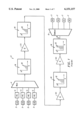
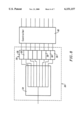
- FIG. 1 shows a graphical representation of a typical communication link 2 of an optical network.
- a plurality of light generators (LG) 3 provide respective component signals 12 of select wavelengths that are combined by a multiplexer 4 to produce the multi-wavelength optical beam 14.
- a plurality of pre-emphasis devices (PE) 5 attenuate selectively each of the respective component signals 12.
- a plurality of amplifiers 20 amplify the optical beam 14 to compensate for fiber loss as the beam passes therethrough.
- the signal components 12 of the optical beam are then separated by a demultiplexer 6 and provided to a corresponding receiver (R) 7.
- the prior art 2 does not provide any compensation other than pre-emphasis to overcome the nonuniform gain of the each amplifier 20.
- the differential of the output power of each of the channels increase after each gain stage 20.
- the only compensation provided by the prior art is adjustment of the pre-emphasis devices 5 for amplifying each channel 12 a predetermined amount to ensure that the output power of each channel are of acceptable power and signal-to-noise ratio.
- an optical amplifier amplifies substantially equally a plurality of component signals of a multi-wavelength optical beam transiting an optical network.
- Each component signal has an amplitude and a unique wavelength.
- the amplifier includes amplifying means for generating amplified component signals. The amplitude of each amplified component signal is respectively increased by a selected value.
- the amplifier further includes equalization means for generating, in response to control signals, equalized component signals from the amplified component signals.
- the equalized component signals have respective amplitudes which are adjusted to remove any relative amplitude difference therebetween due to variations in the amplitudes of the component signals of the multi-wavelength optical beam.
- a method for amplifying substantially equally a plurality of component signals of a multi-wavelength optical beam transiting an optical network, in which each component signal has an amplitude and a unique wavelength includes a step of first amplifying the amplitude of each component signal by a respective amount. The amplitude of each amplified component signal is then adjusted, in response to control signals, to compensate for the varying, nonuniform gain of the amplifying means such that any relative amplitude difference therebetween due to variations in the amplitudes of said component signals of the multi-wavelength optical beam are removed.
- FIG. 1 is a graphical representation of a prior art communication link of an optical network.
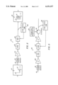
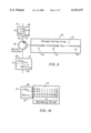
- FIG. 2 is a diagrammatic block diagram of an optical amplifier of the type embodying the present invention.
- FIG. 3 is a diagrammatic block diagram of an alternative embodiment of an optical amplifier of the type embodying the present invention.
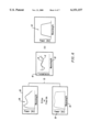
- FIG. 4 is a graphical representation of the gain of an optical signal as a function of frequency for an erbium doped fluoride host glass.
- FIG. 5 is a graphical representation of the gain of an optical signal as a function of frequency for an erbium doped silica host glass fiber.
- FIG. 6 is a graphical representation of the gain equalization using a gain flattening module of the type shown in FIG. 2.
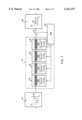
- FIG. 7 is a block diagram representative of the dynamic gain equalization module of FIG. 2.
- FIG. 8 is a block diagram representative of the Loop Status Monitor of FIG. 2.
- FIG. 9 is illustrative of the circulator and dispersion compensation of FIG. 2.
- FIG. 10 is illustrative of the phenomenon of dispersion and the method of compensation of the dispersion.
- a block diagram of a preferred embodiment of a high performance optical amplifier with the required sophistication to handle reconfigurable networks is generally designated as 10.
- the amplifier provides a substantially uniform gain between each of the channels 12 of a dense wavelength division multiplexed optical beam 14 propagating through an optical fiber 16 of an optical network.
- the amplifier 10 includes an optical isolator 18 that permits the optical beam to pass through and prevent optical noise from propagating back through the optical fiber.
- the optical amplifier further includes a gain stage (G) 20, a gain flattening module (GFM) 22 and a gain equalization module (GEM) 24 connected in series.
- G gain stage
- GFM gain flattening module
- GEM gain equalization module
- the amplified signal then passes through the gain flattening module 22 and the gain equalization module 24.
- the gain flattening module selectively attenuate each of the channels 12 to compensate for the fixed nonuniform gain characteristics of the gain stage 20 which will be described in greater detail hereinafter.
- the gain equalization module attenuates dynamically each of the channels in response to control signals provided by a loop status monitor (LSM) 28 to equalize the amplitude of each of the channels.
- LSM loop status monitor
- the loop status monitor 28 determines the amplitude of each channel and generates the corresponding control signals provided to the gain equalization module.
- Each of the control signals are representative of the degree of attenuation required to equalize the output signal of the amplifier.
- the optical amplifier 20 may also include a second gain stage (G) 30 disposed in series after the gain equalization module 24, and/or a circulator 32 and dispersion compensator 34 disposed in series before the loop status monitor 28.
- G second gain stage
- Each of the gain stages 20,30 include an optical fiber doped with a rare earth ion, such as erbium and praseodymium.
- the gain spectrum of these doped optical fibers is not uniform, and is also dependent on the input power, the spectrum of the optical beam and the composition of the fiber.
- the gain can vary from 3 to 10 dB depending upon the glass composition of the fiber.
- FIG. 4 shows a plot 36 of the gain spectrum of an optical signal passing through an erbium doped fluoride host glass fiber.
- FIG. 5 shows a plot 38 of the gain spectrum of an optical signal passing through an erbium doped silica host glass fiber.
- a fluoride host glass fiber is preferable because the gain across the desired spectrum is more uniform, having less gain variation between the channels, and therefore requires less compensation, but has mechanical and hydroscopic properties which make it undesirable to work with.
- the gain flattening module 22 is adapted to compensate for the known variation of the gain spectrum of the gain stage 20.
- the gain flattening module flattens the gain or, in other words, selectively attenuates the gain spectrum so that the gain differential between each channel is preferably approximately 0.1-0.5 dB.
- the selective attenuation by the gain flattening module 12 may be provided by dielectric filters or fiber gratings, such as Long Period Gratings as shown in U.S. Pat. No. 5,430,817.
- FIG. 6 includes a pair of curves 36,38 showing the amplified amplitude of the optical beam from gain stage 20 as a function of wavelength.
- the gain stage 20 of plot 36 comprises an erbium doped fluoride host glass fiber and the gain stage of curve 38 comprises an erbium doped silica host glass fiber.
- the attenuation of the amplified signal by the gain flattening module is graphically shown in curve 40.
- a solid curve 41 represents the attenuation of the input optical beam as a function of the wavelength for silica host glass fiber and a dotted curve 43 represents the attenuation of the input optical beam as a function of the wavelength for fluoride host glass fiber.
- the attenuation for each doped fiber is proportionally inverse to its respective gain spectrum 36,38.
- the resulting gain spectrum from each respective doped fiber and gain flattening module is substantially equal between each channel, as shown in curve 42.
- the passive gain flattening module 22 may not be required. This is true in the case where the gain equalization module 24 has sufficient bandwidth and dynamic range to provide both the gain flattening function and the gain equalization function simultaneously.
- the flattened optical signal from the gain flattening module 22 then propagates to the gain equalization module 24 which substantially equalizes dynamically the amplitude of each channel 12.
- Dynamic gain equalization is necessary to compensate for the dynamic gain changes of the gain stage 20, such as gain tilt, gain ripple, hole burning, transient gain fluctuations, and any gain fluctuations from the gain flattening module 22.
- gain tilt is a function of the input power and spectra of the transmitted channels. As channels are added and subtracted from the optical beam, the input power and spectrum changes and effectively "tilts" the gain of the amplifier in dependence of the wavelength of the channels.
- the gain equalization module 24 selectively attenuates each respective channel in accordance to control signals provided by the loop status monitor 28.
- the gain equalization module 24 incorporates an array of wavelength tunable fiber Bragg gratings 50 to attenuate each channel 12.
- Each grating 50 is nominally aligned to a channel such that the transmission through the grating is varied by tuning the Bragg wavelength of the grating.
- the loop status monitor 28 measures the amplitude or power of each channel and provides a control signal back to each respective tunable grating 50 of the gain equalization module 24.
- Each grating 50 then attenuates each channel 12 in response to the corresponding control signal to vary the amplitude of each transmission through the grating, so that the amplitude of each channel is substantially equal at the amplifier's output terminal 52.
- a preferred gain equalization module 24 is described in greater detail in Applicants' co-pending application for "Dynamic Gain Equalization Module", attorney docket no. 4827-11, which is incorporated herein by reference.
- the loop status monitor 28 includes a dense wavelength division demultiplexing arrayed waveguide 54 and a detector array 56 for providing a corresponding control signal to each of the tunable gratings 50 of the gain equalization module 24 (See FIG. 7).
- the loop status monitor serves the function of a low cost optical spectrum analyzer.
- planar array waveguides are currently made using silica on silicon technology. These are silica on silicon waveguides and are commercially available for multiplexing/demultiplexing in WDM networks.
- the planar waveguides include a plurality of precision ion implanted regions for separating each channel of the optical beam and directs them to a corresponding detector element 58 of the detector array 56.
- any passive multiplexing/demultiplexing dielectric filter based device or Fiber Bragg Grating based device could be used with appropriate modifications.
- WDM 1 ⁇ N arrayed demultiplexer waveguides are presently commercially available. These commercial waveguides include multiple fiber pigtail outputs that result in relatively high excess losses (approximately 7 dB).
- the waveguide embodied in the present invention is butt-coupled to each of the elements 58 of the detector array, and thus eliminates the output pigtails and reduces the associated insertion loss.
- the detector elements 58 generates concurrently an output signal for each channel 12 that is representative of the amplitude of each channel.
- the output signals of each detector element 58 are provided to a controller 60.
- the controller 60 In response to these output signals, the controller 60 generates corresponding control signals representative of the degree of attenuation required to equalize the output signal of each channel of the amplifier 10.
- Each respective control signal is indicative of the difference between the amplitude of the respective channel and the channel having the least amplitude.
- loop status monitor 28 provides greater than 15 dB of channel isolation without additional filtering. If there is excessive cross-talk between the channels, Bragg gratings may be written directly into the silica of the waveguide to increase the channel isolation and enhance the resolution in the monitor 28. Increased channel isolation also permits blocking of the WDM signals by tuning the grating, such as by heating, which permits detection of the amplifier noise level. This information allows the signal-to-noise ratio to be computed.
- loop status monitor 28 Another benefit of the loop status monitor 28 is the parallel monitoring of the channels 12 of the optical signal.
- the output of the loop status monitor may also be used to monitor the "health" and status, such as channel power and channel signal-to-noise ratio, at various locations within the network.
- an AOTF configured as a spectrum analyzer along with appropriate control and feedback electronics can be used as a loop status monitor 28.
- the AOTF scans through each network channel 12, sequentially, monitoring the power in each channel. The selection of wavelengths can be changed in approximately 10 microseconds making the spectrum analyzer reconfiguration virtually instantaneous. From this data a channel intensity profile can be constructed and fed to appropriate network elements including the gain equalization module 24, programmable add-drop modules and network health monitoring systems.
- the use of an AOTF as a loop status monitor 28 is described in greater detail in Applicants' co-pending application for "Loop Status Monitor For Determining The Amplitude Of The Signal Components Of A Multi-Wavelength Optical Beam", attorney docket no. 4827-13, which is incorporated herein by reference.
- a second gain stage 30 may be inserted in series after the gain equalization module 24.
- the second gain stage 30 is similar to the above-described gain stage 20 that includes a doped optical fiber of a rare earth ion, such as erbium and praseodymium.
- the nonuniform gain spectrum of the second gain stage 30 is corrected by the gain equalization module 24 in response to the control signals of the loop status monitor 28.
- a circulator 32 and dispersion compensator 34 may be connected in series before the loop status monitor 28 as shown in FIG. 10.
- Each channel 12 is composed a spectrum of a plurality of optical wavelengths 68,70 that are represented graphically in FIGS. 9 and 10 as a long wavelength 68 and a short wavelength 70.
- Dispersion is a result of a channel 12 "chirping" which causes the wavelengths 68,70 of a channel to pass through the optical fiber at different rates resulting in a temporal smearing of the signal. Dispersion limits the practical link length in 10 Gbit/second transmission systems and is defined as a temporal broadening of a channel usually most clearly seen at the transition of the signal between a high and low state.
- the circulator 32 receives the input optical beam 67 and directs it to the dispersion compensator 34.
- the dispersion compensator 34 includes a chirped grating array 72 fabricated in a known manner for selectively delaying the transmission of the wavelengths 68, 70 of the spectrum of each channel 12, and thereby reduce the temporal broadening or smearing caused by dispersion.
- Each channel propagates through each respective chirped grating 74 to compensate for dispersion of each respective channel.
- the optical circulator 32 then receives the optical beam 14 reflected back from the dispersion compensator 34 and directs the beam to the output 76 of the circulator.
- the operation of the dispersion compensator 34 is schematically shown in FIG. 11.
- the optical wavelengths 68, 70 that comprise the channel 12 propagate through that channel's respective chirped grating 74, wherein the long wavelength 68 lags the short wavelength 70 by an amount at the input of the grating 74.
- the grating 74 then reflects each wavelength 68, 70 of the channel back to the circulator 32 to compensate for the effects of dispersion.
- the propagation time through the chirped grating for the short wavelength 70 is less than that of the long wavelength 68 by a predetermined amount. Consequently, the temporal smearing is removed, and the optical signal of channel 12 thereafter more closely resembles the signal originally presented to the optical network.
- a dispersion compensating fiber that is commercially available may be used.
Abstract
Description
Claims (17)
Priority Applications (5)
| Application Number | Priority Date | Filing Date | Title |
|---|---|---|---|
| US08/884,747 US6151157A (en) | 1997-06-30 | 1997-06-30 | Dynamic optical amplifier |
| CA002294636A CA2294636C (en) | 1997-06-30 | 1998-06-25 | Dynamic optical amplifier |
| AU81745/98A AU8174598A (en) | 1997-06-30 | 1998-06-25 | Dynamic optical amplifier |
| DE69834198T DE69834198T2 (en) | 1997-06-30 | 1998-06-25 | DYNAMIC OPTICAL AMPLIFIER |
| EP98931695A EP1013021B1 (en) | 1997-06-30 | 1998-06-25 | Dynamic optical amplifier |
Applications Claiming Priority (1)
| Application Number | Priority Date | Filing Date | Title |
|---|---|---|---|
| US08/884,747 US6151157A (en) | 1997-06-30 | 1997-06-30 | Dynamic optical amplifier |
Publications (1)
| Publication Number | Publication Date |
|---|---|
| US6151157A true US6151157A (en) | 2000-11-21 |
Family
ID=25385305
Family Applications (1)
| Application Number | Title | Priority Date | Filing Date |
|---|---|---|---|
| US08/884,747 Expired - Lifetime US6151157A (en) | 1997-06-30 | 1997-06-30 | Dynamic optical amplifier |
Country Status (5)
| Country | Link |
|---|---|
| US (1) | US6151157A (en) |
| EP (1) | EP1013021B1 (en) |
| AU (1) | AU8174598A (en) |
| CA (1) | CA2294636C (en) |
| DE (1) | DE69834198T2 (en) |
Cited By (54)
| Publication number | Priority date | Publication date | Assignee | Title |
|---|---|---|---|---|
| US6343165B1 (en) | 1998-02-12 | 2002-01-29 | Novera Optics, Inc. | Optical add drop multiplexer |
| US6357913B1 (en) | 1998-02-12 | 2002-03-19 | Novera Optics, Inc. | Add/drop acousto-optic filter |
| US6359726B1 (en) * | 1999-03-02 | 2002-03-19 | Fujitsu Limited | Wavelength division multiplexing optical amplifier with function of gain-equalizing and optical communication system |
| US6381064B1 (en) * | 1998-02-04 | 2002-04-30 | Fujitsu Limited | Method for gain equalization, and device and system for use in carrying out the method |
| US20020109908A1 (en) * | 2001-02-12 | 2002-08-15 | Koteles Emil S. | Optical dynamic gain amplifier |
| US6438010B1 (en) | 2001-03-02 | 2002-08-20 | Onetta, Inc. | Drive circuits for microelectromechanical systems devices |
| US6445493B2 (en) * | 1999-01-29 | 2002-09-03 | Corning Incorporated | Balanced gain flattening filters |
| US6459526B1 (en) * | 1999-08-09 | 2002-10-01 | Corning Incorporated | L band amplifier with distributed filtering |
| US20020145778A1 (en) * | 2001-03-16 | 2002-10-10 | Photuris, Inc. | Wavelength division multiplexed optical communication system having a reconfigurable optical switch and a tunable backup laser transmitter |
| US20020159679A1 (en) * | 2001-03-16 | 2002-10-31 | Strasser Thomas Andrew | Method and apparatus for providing gain equalization to an optical signal in an optical communication system |
| US6483631B1 (en) | 2001-06-05 | 2002-11-19 | Onetta, Inc. | Optical amplifier spectral tilt controllers |
| US20020171917A1 (en) * | 2001-05-17 | 2002-11-21 | Lelic Muhidin A. | Optical amplifier performance controller and method of use |
| US6493129B2 (en) | 1998-01-23 | 2002-12-10 | Fujitsu Limited | Tunable optical filter |
| US6496302B1 (en) * | 1998-09-07 | 2002-12-17 | Nec Corporation | Optical amplifier |
| US6498677B1 (en) | 2000-10-23 | 2002-12-24 | Onetta, Inc. | Optical amplifier systems with transient control |
| US6504989B1 (en) | 2000-10-23 | 2003-01-07 | Onetta, Inc. | Optical equipment and methods for manufacturing optical communications equipment for networks |
| US6510261B2 (en) | 1997-06-06 | 2003-01-21 | Novera Optics, Inc. | Acousto-optic variable attenuator with active cancellation of back reflections |
| US20030020990A1 (en) * | 2001-07-27 | 2003-01-30 | Alcatel | Method and system for automatic gain equalization in an optical transmission system using WDM technique |
| US20030026529A1 (en) * | 2001-08-06 | 2003-02-06 | Durkin Michael Kevan | Optical demultiplexer |
| US20030039003A1 (en) * | 2001-08-27 | 2003-02-27 | Bogdan Jakobik | Architectural arrangement for core optical networks |
| US6529316B1 (en) | 2001-05-03 | 2003-03-04 | Onetta, Inc. | Optical network equipment with optical channel monitor and dynamic spectral filter alarms |
| US6532323B2 (en) | 1997-06-06 | 2003-03-11 | Novera Optics, Inc. | Acousto-optic filter |
| US6532322B1 (en) | 1997-06-06 | 2003-03-11 | Novera Optics, Inc. | Channel equalizer with acousto-optic variable attenuators |
| US6535324B1 (en) | 2000-05-23 | 2003-03-18 | Novera Optics, Inc. | Bi-directional wavelength-selective optical data apparatus |
| US6535665B1 (en) | 1998-02-12 | 2003-03-18 | Novera Optics, Inc. | Acousto-optic devices utilizing longitudinal acoustic waves |
| US6539148B1 (en) | 1997-06-06 | 2003-03-25 | Novera Optics, Inc. | Channel equalizer with acousto-optic variable attenuators |
| US6545800B1 (en) | 2001-06-05 | 2003-04-08 | Onetta, Inc. | Depolarizers for optical channel monitors |
| US20030068130A1 (en) * | 2001-10-09 | 2003-04-10 | Photon-X, Inc. | Dynamic gain-equalizing filter based on polymer optical waveguide gratings |
| KR20030032291A (en) * | 2001-10-17 | 2003-04-26 | 주식회사 머큐리 | Gain-locked optical fiber amplifier |
| US20030081308A1 (en) * | 2001-08-20 | 2003-05-01 | So John Ling Wing | Optical system and method |
| US6567587B2 (en) * | 2000-03-29 | 2003-05-20 | The Furukawa Electric Co., Ltd. | Dispersion compensator and dispersion-compensating module employing the same |
| US6577416B1 (en) * | 1997-11-24 | 2003-06-10 | Alcatel | Channel control in a wavelength division multiplexed communications network |
| US6580550B1 (en) * | 1999-07-06 | 2003-06-17 | Hitachi, Ltd. | Filter with variable transmission character, optical transmission equipment and method of optical transmission |
| US20030123830A1 (en) * | 2001-11-19 | 2003-07-03 | Aydin Yeniay | Optical amplifier with gain flattening filter |
| US6603597B2 (en) | 2001-06-08 | 2003-08-05 | Photon-X, Inc. | Dual mode programmable optical logarithmic amplifier driver |
| US6621968B1 (en) | 1998-12-10 | 2003-09-16 | Ultraband Fiber Optics, Inc. | Optical fiber for broadband optical devices and optical fiber devices using thereof |
| US6631224B2 (en) | 1997-06-06 | 2003-10-07 | Novera Optics, Inc. | Tunable filter with core mode blocker |
| US6640027B2 (en) | 1997-06-06 | 2003-10-28 | Novera Optics, Inc. | Gain flattening tunable filter |
| KR100419608B1 (en) * | 2001-09-24 | 2004-02-25 | 한국전자통신연구원 | Power equalization device and method for wdm all optical network |
| KR100421136B1 (en) * | 2002-03-19 | 2004-03-04 | 삼성전자주식회사 | Wide band erbium doped fiber amplifier and wavelength division multiplexing transmission system therewith |
| US6728026B2 (en) * | 1998-07-14 | 2004-04-27 | Novera Optics, Inc. | Dynamically tunable optical amplifier and fiber optic light source |
| US6731424B1 (en) | 2001-03-15 | 2004-05-04 | Onetta, Inc. | Dynamic gain flattening in an optical communication system |
| US6768579B2 (en) * | 2000-08-18 | 2004-07-27 | Siemens Aktiengesellschaft | Optical amplifier arrangement having a variably settable attenuator |
| US6801686B2 (en) | 1997-06-06 | 2004-10-05 | Novera Optics, Inc. | Methods and apparatus for measuring the power spectrum of optical signals |
| US6835013B2 (en) | 2000-10-24 | 2004-12-28 | Esselte | Label printer |
| US6847742B2 (en) | 1997-06-16 | 2005-01-25 | Novera Optics, Inc. | Tunable dynamic gain flattening filter using polarization delays |
| US6850655B2 (en) | 1997-06-16 | 2005-02-01 | Novera Optics, Inc. | Optical apparatus with faraday rotator, static gain flattening filter and variable optical attenuator |
| US6904188B1 (en) | 2001-03-16 | 2005-06-07 | Novera Optics, Inc. | Acousto-optic tunable filter having improved wave-damping capability |
| US6941079B1 (en) * | 2001-05-24 | 2005-09-06 | Cisco Technology, Inc. | Optical demultiplexer with multi-channel power control and tilt compensation |
| US6952309B1 (en) * | 1999-07-09 | 2005-10-04 | Sumitomo Electric Industries, Ltd. | Optical amplifier and optical amplification method |
| US20060051093A1 (en) * | 2004-08-11 | 2006-03-09 | Massimo Manna | System and method for spectral loading an optical transmission system |
| US20060072188A1 (en) * | 2004-10-06 | 2006-04-06 | Jds Uniphase Corporation | Spectrally resolved fast monitor |
| WO2006063473A1 (en) * | 2004-12-16 | 2006-06-22 | Vectronix Ag | Non temperature stabilized pulsed laser diode and all fibre power amplifier |
| US7292787B1 (en) * | 1999-02-19 | 2007-11-06 | Fujitsu Limited | Selected-wavelength tuning filter and optical add/drop multiplexer |
Citations (55)
| Publication number | Priority date | Publication date | Assignee | Title |
|---|---|---|---|---|
| US4284663A (en) * | 1976-05-10 | 1981-08-18 | Bell Telephone Laboratories, Incorporated | Fabrication of optical waveguides by indiffusion of metals |
| US4474427A (en) * | 1979-05-07 | 1984-10-02 | Canadian Patents & Development Limited | Optical fiber reflective filter |
| US4953939A (en) * | 1984-07-11 | 1990-09-04 | Stc Plc | Optical fibre transmission systems |
| US4984861A (en) * | 1989-03-27 | 1991-01-15 | United Technologies Corporation | Low-loss proton exchanged waveguides for active integrated optic devices and method of making same |
| US5026137A (en) * | 1988-09-26 | 1991-06-25 | Canon Kabushiki Kaisha | Light signal transmission system |
| US5042898A (en) * | 1989-12-26 | 1991-08-27 | United Technologies Corporation | Incorporated Bragg filter temperature compensated optical waveguide device |
| US5077816A (en) * | 1989-12-26 | 1991-12-31 | United Technologies Corporation | Fiber embedded grating frequency standard optical communication devices |
| US5107360A (en) * | 1990-11-05 | 1992-04-21 | General Instrument Corporation | Optical transmission of RF subcarriers in adjacent signal bands |
| US5115338A (en) * | 1990-05-30 | 1992-05-19 | At&T Bell Laboratories | Multi-stage optical amplifier |
| US5119447A (en) * | 1990-11-06 | 1992-06-02 | General Instrument Corporation | Apparatus and method for externally modulating an optical carrier |
| US5134620A (en) * | 1990-11-20 | 1992-07-28 | General Instrument Corporation | Laser with longitudinal mode selection |
| US5140456A (en) * | 1991-04-08 | 1992-08-18 | General Instrument Corporation | Low noise high power optical fiber amplifier |
| US5148503A (en) * | 1991-05-29 | 1992-09-15 | Crystal Technology, Inc | Apparatus and method for linearized cascade coupled integrated optical modulator |
| US5151908A (en) * | 1990-11-20 | 1992-09-29 | General Instrument Corporation | Laser with longitudinal mode selection |
| US5153762A (en) * | 1990-03-19 | 1992-10-06 | General Instrument Corporation | Method and apparatus for recovering AM channell signals distributed on an optical fiber |
| US5159601A (en) * | 1991-07-17 | 1992-10-27 | General Instrument Corporation | Method for producing a tunable erbium fiber laser |
| US5166821A (en) * | 1991-03-12 | 1992-11-24 | General Instrument Corporation | Reduction of non-linear effects in optical fiber communication systems and method of using same |
| US5168534A (en) * | 1991-12-09 | 1992-12-01 | United Technologies Corporation | Cascaded optic modulator arrangement |
| US5187760A (en) * | 1992-01-23 | 1993-02-16 | General Instrument Corporation | Wavelength selective coupler for high power optical communications |
| US5191586A (en) * | 1991-07-18 | 1993-03-02 | General Instrument Corporation | Narrow band incoherent optical carrier generator |
| US5200964A (en) * | 1991-03-12 | 1993-04-06 | General Instrument Corporation | Broad linewidth lasers for optical fiber communication systems |
| US5208819A (en) * | 1992-01-23 | 1993-05-04 | General Instrument Corporation | Optical source with frequency locked to an in-fiber grating resonantor |
| US5210631A (en) * | 1989-12-22 | 1993-05-11 | General Instrument Corporation | Transmission of AM-VSB video signals over an optical fiber |
| US5210633A (en) * | 1990-09-12 | 1993-05-11 | General Instrument Corporation | Apparatus and method for linearizing the operation of an external optical modulator |
| US5222089A (en) * | 1992-01-08 | 1993-06-22 | General Instrument Corporation | Optical signal source for overcoming distortion generated by an optical amplifier |
| US5231529A (en) * | 1990-12-19 | 1993-07-27 | Nec Corporation | Light amplifier for multi-wavelength signals |
| US5243609A (en) * | 1990-11-20 | 1993-09-07 | General Instrument Corporation | Laser with longitudinal mode selection |
| US5257124A (en) * | 1991-08-15 | 1993-10-26 | General Instrument Corporation | Low distortion laser system for AM fiber optic communication |
| US5257125A (en) * | 1991-11-27 | 1993-10-26 | Xerox Corporation | Afocal optical system for focus error correction in laser scanning systems |
| US5260823A (en) * | 1990-05-21 | 1993-11-09 | University Of Southampton | Erbium-doped fibre amplifier with shaped spectral gain |
| US5268910A (en) * | 1991-07-18 | 1993-12-07 | General Instrument Corporation | Superluminescent optical source |
| US5271024A (en) * | 1992-07-27 | 1993-12-14 | General Instrument Corporation | Optical fiber amplifier and laser with flattened gain slope |
| US5283686A (en) * | 1992-07-27 | 1994-02-01 | General Instrument Corporation, Jerrold Communications | Optical systems with grating reflector |
| US5404413A (en) * | 1993-12-14 | 1995-04-04 | At&T Corp. | Optical circulator for dispersion compensation |
| US5430817A (en) * | 1994-03-31 | 1995-07-04 | At&T Corp. | Optical systems and devices using long period spectral shaping devices |
| US5436760A (en) * | 1993-07-14 | 1995-07-25 | Nec Corporation | Optical fiber amplifier with gain equalizing circuit |
| EP0695050A1 (en) * | 1994-07-25 | 1996-01-31 | PIRELLI CAVI S.p.A. | Amplified telecommunication system for wavelength-division multiplexing transmissions capable of limiting variations in the output power |
| US5504609A (en) * | 1995-05-11 | 1996-04-02 | Ciena Corporation | WDM optical communication system with remodulators |
| GB2295247A (en) * | 1994-11-16 | 1996-05-22 | Northern Telecom Ltd | Optical waveguide grating filter having two or three gratings |
| US5541766A (en) * | 1994-11-30 | 1996-07-30 | At&T Corp. | Gain control for optically amplified systems |
| US5557442A (en) * | 1993-06-04 | 1996-09-17 | Ciena Corporation | Optical amplifiers with flattened gain curves |
| US5583689A (en) * | 1992-06-01 | 1996-12-10 | British Telecommunications Public Limited Company | Filter with preselected attenuation/wavelength characteristic |
| US5608825A (en) * | 1996-02-01 | 1997-03-04 | Jds Fitel Inc. | Multi-wavelength filtering device using optical fiber Bragg grating |
| EP0762691A2 (en) * | 1995-09-08 | 1997-03-12 | Alcatel N.V. | Method and device for equalising the respective power levels of the channels of a spectrally multiplexed signal |
| EP0762569A2 (en) * | 1995-08-23 | 1997-03-12 | Fujitsu Limited | Method and apparatus for controlling optical amplifier used for optically amplifying wavelength-division multiplexed signal |
| WO1997010658A1 (en) * | 1995-09-15 | 1997-03-20 | Integrated Optical Components Limited | Method for independently controlling the wavelength component powers in an optical wavelength division multiplexed transmission system |
| EP0766423A2 (en) * | 1995-09-27 | 1997-04-02 | Nec Corporation | Optical wavelength-division multiplexing transmission system |
| US5623565A (en) * | 1992-06-01 | 1997-04-22 | British Telecommunications Public Limited Company | Optical sensor/actuator communication system with common control site independently responding to inputs from sensors and controlling associated actuators |
| US5627848A (en) * | 1995-09-05 | 1997-05-06 | Imra America, Inc. | Apparatus for producing femtosecond and picosecond pulses from modelocked fiber lasers cladding pumped with broad area diode laser arrays |
| US5633748A (en) * | 1996-03-05 | 1997-05-27 | The United States Of America As Represented By The Secretary Of The Navy | Fiber optic Bragg grating demodulator and sensor incorporating same |
| US5636054A (en) * | 1994-09-29 | 1997-06-03 | Alcatel N.V. | Regulated optical amplifier having an optical circulator |
| US5636301A (en) * | 1994-06-02 | 1997-06-03 | Northern Telecom Limited | Optical waveguide amplifiers |
| US5638473A (en) * | 1994-11-16 | 1997-06-10 | Northern Telecom Limited | Optical waveguide grating filter |
| US5691999A (en) * | 1994-09-30 | 1997-11-25 | United Technologies Corporation | Compression-tuned fiber laser |
| US5696615A (en) * | 1995-11-13 | 1997-12-09 | Ciena Corporation | Wavelength division multiplexed optical communication systems employing uniform gain optical amplifiers |
-
1997
- 1997-06-30 US US08/884,747 patent/US6151157A/en not_active Expired - Lifetime
-
1998
- 1998-06-25 CA CA002294636A patent/CA2294636C/en not_active Expired - Lifetime
- 1998-06-25 DE DE69834198T patent/DE69834198T2/en not_active Expired - Lifetime
- 1998-06-25 AU AU81745/98A patent/AU8174598A/en not_active Abandoned
- 1998-06-25 EP EP98931695A patent/EP1013021B1/en not_active Expired - Lifetime
Patent Citations (58)
| Publication number | Priority date | Publication date | Assignee | Title |
|---|---|---|---|---|
| US4284663A (en) * | 1976-05-10 | 1981-08-18 | Bell Telephone Laboratories, Incorporated | Fabrication of optical waveguides by indiffusion of metals |
| US4474427A (en) * | 1979-05-07 | 1984-10-02 | Canadian Patents & Development Limited | Optical fiber reflective filter |
| US4953939A (en) * | 1984-07-11 | 1990-09-04 | Stc Plc | Optical fibre transmission systems |
| US5026137A (en) * | 1988-09-26 | 1991-06-25 | Canon Kabushiki Kaisha | Light signal transmission system |
| US4984861A (en) * | 1989-03-27 | 1991-01-15 | United Technologies Corporation | Low-loss proton exchanged waveguides for active integrated optic devices and method of making same |
| US5210631A (en) * | 1989-12-22 | 1993-05-11 | General Instrument Corporation | Transmission of AM-VSB video signals over an optical fiber |
| US5042898A (en) * | 1989-12-26 | 1991-08-27 | United Technologies Corporation | Incorporated Bragg filter temperature compensated optical waveguide device |
| US5077816A (en) * | 1989-12-26 | 1991-12-31 | United Technologies Corporation | Fiber embedded grating frequency standard optical communication devices |
| US5153762A (en) * | 1990-03-19 | 1992-10-06 | General Instrument Corporation | Method and apparatus for recovering AM channell signals distributed on an optical fiber |
| US5260823A (en) * | 1990-05-21 | 1993-11-09 | University Of Southampton | Erbium-doped fibre amplifier with shaped spectral gain |
| US5115338A (en) * | 1990-05-30 | 1992-05-19 | At&T Bell Laboratories | Multi-stage optical amplifier |
| US5210633A (en) * | 1990-09-12 | 1993-05-11 | General Instrument Corporation | Apparatus and method for linearizing the operation of an external optical modulator |
| US5107360A (en) * | 1990-11-05 | 1992-04-21 | General Instrument Corporation | Optical transmission of RF subcarriers in adjacent signal bands |
| US5119447A (en) * | 1990-11-06 | 1992-06-02 | General Instrument Corporation | Apparatus and method for externally modulating an optical carrier |
| US5243609A (en) * | 1990-11-20 | 1993-09-07 | General Instrument Corporation | Laser with longitudinal mode selection |
| US5151908A (en) * | 1990-11-20 | 1992-09-29 | General Instrument Corporation | Laser with longitudinal mode selection |
| US5134620A (en) * | 1990-11-20 | 1992-07-28 | General Instrument Corporation | Laser with longitudinal mode selection |
| US5231529A (en) * | 1990-12-19 | 1993-07-27 | Nec Corporation | Light amplifier for multi-wavelength signals |
| US5166821A (en) * | 1991-03-12 | 1992-11-24 | General Instrument Corporation | Reduction of non-linear effects in optical fiber communication systems and method of using same |
| US5200964A (en) * | 1991-03-12 | 1993-04-06 | General Instrument Corporation | Broad linewidth lasers for optical fiber communication systems |
| US5140456A (en) * | 1991-04-08 | 1992-08-18 | General Instrument Corporation | Low noise high power optical fiber amplifier |
| US5148503A (en) * | 1991-05-29 | 1992-09-15 | Crystal Technology, Inc | Apparatus and method for linearized cascade coupled integrated optical modulator |
| US5159601A (en) * | 1991-07-17 | 1992-10-27 | General Instrument Corporation | Method for producing a tunable erbium fiber laser |
| US5191586A (en) * | 1991-07-18 | 1993-03-02 | General Instrument Corporation | Narrow band incoherent optical carrier generator |
| US5268910A (en) * | 1991-07-18 | 1993-12-07 | General Instrument Corporation | Superluminescent optical source |
| US5257124A (en) * | 1991-08-15 | 1993-10-26 | General Instrument Corporation | Low distortion laser system for AM fiber optic communication |
| US5257125A (en) * | 1991-11-27 | 1993-10-26 | Xerox Corporation | Afocal optical system for focus error correction in laser scanning systems |
| US5168534A (en) * | 1991-12-09 | 1992-12-01 | United Technologies Corporation | Cascaded optic modulator arrangement |
| US5222089A (en) * | 1992-01-08 | 1993-06-22 | General Instrument Corporation | Optical signal source for overcoming distortion generated by an optical amplifier |
| US5208819A (en) * | 1992-01-23 | 1993-05-04 | General Instrument Corporation | Optical source with frequency locked to an in-fiber grating resonantor |
| US5187760A (en) * | 1992-01-23 | 1993-02-16 | General Instrument Corporation | Wavelength selective coupler for high power optical communications |
| US5583689A (en) * | 1992-06-01 | 1996-12-10 | British Telecommunications Public Limited Company | Filter with preselected attenuation/wavelength characteristic |
| US5623565A (en) * | 1992-06-01 | 1997-04-22 | British Telecommunications Public Limited Company | Optical sensor/actuator communication system with common control site independently responding to inputs from sensors and controlling associated actuators |
| US5283686A (en) * | 1992-07-27 | 1994-02-01 | General Instrument Corporation, Jerrold Communications | Optical systems with grating reflector |
| US5271024A (en) * | 1992-07-27 | 1993-12-14 | General Instrument Corporation | Optical fiber amplifier and laser with flattened gain slope |
| US5557442A (en) * | 1993-06-04 | 1996-09-17 | Ciena Corporation | Optical amplifiers with flattened gain curves |
| US5579143A (en) * | 1993-06-04 | 1996-11-26 | Ciena Corporation | Optical system with tunable in-fiber gratings |
| US5436760A (en) * | 1993-07-14 | 1995-07-25 | Nec Corporation | Optical fiber amplifier with gain equalizing circuit |
| US5404413A (en) * | 1993-12-14 | 1995-04-04 | At&T Corp. | Optical circulator for dispersion compensation |
| US5430817A (en) * | 1994-03-31 | 1995-07-04 | At&T Corp. | Optical systems and devices using long period spectral shaping devices |
| US5636301A (en) * | 1994-06-02 | 1997-06-03 | Northern Telecom Limited | Optical waveguide amplifiers |
| US5701194A (en) * | 1994-07-14 | 1997-12-23 | Pirelli Cavi S.P.A. | Amplified telecommunication system for wavelength-division multiplexing transmissions capable of limiting variations in the output power |
| EP0695050A1 (en) * | 1994-07-25 | 1996-01-31 | PIRELLI CAVI S.p.A. | Amplified telecommunication system for wavelength-division multiplexing transmissions capable of limiting variations in the output power |
| US5636054A (en) * | 1994-09-29 | 1997-06-03 | Alcatel N.V. | Regulated optical amplifier having an optical circulator |
| US5691999A (en) * | 1994-09-30 | 1997-11-25 | United Technologies Corporation | Compression-tuned fiber laser |
| GB2295247A (en) * | 1994-11-16 | 1996-05-22 | Northern Telecom Ltd | Optical waveguide grating filter having two or three gratings |
| US5638473A (en) * | 1994-11-16 | 1997-06-10 | Northern Telecom Limited | Optical waveguide grating filter |
| US5541766A (en) * | 1994-11-30 | 1996-07-30 | At&T Corp. | Gain control for optically amplified systems |
| US5504609A (en) * | 1995-05-11 | 1996-04-02 | Ciena Corporation | WDM optical communication system with remodulators |
| US5745283A (en) * | 1995-08-23 | 1998-04-28 | Fujitsu Limited | Method and apparatus for controlling optical amplifier used for optically amplifying wavelength-division multiplexed signal |
| EP0762569A2 (en) * | 1995-08-23 | 1997-03-12 | Fujitsu Limited | Method and apparatus for controlling optical amplifier used for optically amplifying wavelength-division multiplexed signal |
| US5627848A (en) * | 1995-09-05 | 1997-05-06 | Imra America, Inc. | Apparatus for producing femtosecond and picosecond pulses from modelocked fiber lasers cladding pumped with broad area diode laser arrays |
| EP0762691A2 (en) * | 1995-09-08 | 1997-03-12 | Alcatel N.V. | Method and device for equalising the respective power levels of the channels of a spectrally multiplexed signal |
| WO1997010658A1 (en) * | 1995-09-15 | 1997-03-20 | Integrated Optical Components Limited | Method for independently controlling the wavelength component powers in an optical wavelength division multiplexed transmission system |
| EP0766423A2 (en) * | 1995-09-27 | 1997-04-02 | Nec Corporation | Optical wavelength-division multiplexing transmission system |
| US5696615A (en) * | 1995-11-13 | 1997-12-09 | Ciena Corporation | Wavelength division multiplexed optical communication systems employing uniform gain optical amplifiers |
| US5608825A (en) * | 1996-02-01 | 1997-03-04 | Jds Fitel Inc. | Multi-wavelength filtering device using optical fiber Bragg grating |
| US5633748A (en) * | 1996-03-05 | 1997-05-27 | The United States Of America As Represented By The Secretary Of The Navy | Fiber optic Bragg grating demodulator and sensor incorporating same |
Non-Patent Citations (20)
| Title |
|---|
| "Experimental Demonstration of Dynamic High Speed Equalization of Three WDM Channels Using Acoustoopitic Modulators and A Wavelength Demultiplexer" by Jin-Xing Cai et al., IEEE Photonics Technology Letters, vol. 9, No.5, May. 1997. |
| "Photoinduced Bragg Gratings In Optical Fibers" by William W. Mopey, Gary A. Ball and Gerald Meltz, Optics & Photonics News, Feb. 1994, 7 sheets. |
| "Piriodical" A Publication Of Photonic Integration Research, Inc., No. 12, Feb. 1997. |
| Catalog of Integrated Optical Circuits, Uniphase Telecommunications Products, Electro Optics Products Division, 1997. * |
| Catalog of Integrated Optical Circuits, Uniphase Telecommunications Products, Electro-Optics Products Division, 1997. |
| Experimental Demonstration of Dynamic High Speed Equalization of Three WDM Channels Using Acoustoopitic Modulators and A Wavelength Demultiplexer by Jin Xing Cai et al., IEEE Photonics Technology Letters , vol. 9, No.5, May. 1997. * |
| Huang et al, CLEO 96, pp. 3 4, CMA4. * |
| Huang et al, CLEO'96, pp. 3-4, CMA4. |
| Imai et al, Japanese Journal of Applied Physics, Part 2, (Letters), vol. 35, No. 10A, pp. L1275 L1277, Oct. 1, 1996. * |
| Imai et al, Japanese Journal of Applied Physics, Part 2, (Letters), vol. 35, No. 10A, pp. L1275-L1277, Oct. 1, 1996. |
| Literature regarding "AOTFS route traffic in WDM networks", Lightwave, Jun. 1996. |
| Literature regarding "Piri", Photonic Integration Research, Inc. |
| Literature regarding AOTFS route traffic in WDM networks , Lightwave, Jun. 1996. * |
| Literature regarding Piri , Photonic Integration Research, Inc. * |
| Photoinduced Bragg Gratings In Optical Fibers by William W. Mopey, Gary A. Ball and Gerald Meltz, Optics & Photonics News, Feb. 1994, 7 sheets. * |
| Piriodical A Publication Of Photonic Integration Research, Inc., No. 12, Feb. 1997. * |
| Shehadeh et al, OFC 95 Technical Digest, TuH2, 1995, p. 29. * |
| Shehadeh et al, OFC '95 Technical Digest, TuH2, 1995, p. 29. |
| Su et al, IEEE Photonics Technology Letters, vol. 4, No. 3, Mar. 1992, pp. 269 271. * |
| Su et al, IEEE Photonics Technology Letters, vol. 4, No. 3, Mar. 1992, pp. 269-271. |
Cited By (81)
| Publication number | Priority date | Publication date | Assignee | Title |
|---|---|---|---|---|
| US6801686B2 (en) | 1997-06-06 | 2004-10-05 | Novera Optics, Inc. | Methods and apparatus for measuring the power spectrum of optical signals |
| US6510261B2 (en) | 1997-06-06 | 2003-01-21 | Novera Optics, Inc. | Acousto-optic variable attenuator with active cancellation of back reflections |
| US6532322B1 (en) | 1997-06-06 | 2003-03-11 | Novera Optics, Inc. | Channel equalizer with acousto-optic variable attenuators |
| US6532323B2 (en) | 1997-06-06 | 2003-03-11 | Novera Optics, Inc. | Acousto-optic filter |
| US6539148B1 (en) | 1997-06-06 | 2003-03-25 | Novera Optics, Inc. | Channel equalizer with acousto-optic variable attenuators |
| US6640027B2 (en) | 1997-06-06 | 2003-10-28 | Novera Optics, Inc. | Gain flattening tunable filter |
| US6631224B2 (en) | 1997-06-06 | 2003-10-07 | Novera Optics, Inc. | Tunable filter with core mode blocker |
| US6847742B2 (en) | 1997-06-16 | 2005-01-25 | Novera Optics, Inc. | Tunable dynamic gain flattening filter using polarization delays |
| US6850655B2 (en) | 1997-06-16 | 2005-02-01 | Novera Optics, Inc. | Optical apparatus with faraday rotator, static gain flattening filter and variable optical attenuator |
| US6577416B1 (en) * | 1997-11-24 | 2003-06-10 | Alcatel | Channel control in a wavelength division multiplexed communications network |
| US6717730B2 (en) | 1998-01-23 | 2004-04-06 | Fujitsu Limited | Tunable optical filter |
| US6493129B2 (en) | 1998-01-23 | 2002-12-10 | Fujitsu Limited | Tunable optical filter |
| US6580551B2 (en) * | 1998-02-04 | 2003-06-17 | Fujitsu Limited | Method for gain equalization, and device and system for use in carrying out the method |
| US6693739B2 (en) | 1998-02-04 | 2004-02-17 | Fujitsu Limited | Method for gain equalization, and device and system for use in carrying out the method |
| US6829083B2 (en) | 1998-02-04 | 2004-12-07 | Fujitsu Limited | Method for gain equalization, and device and system for use in carrying out the method |
| US6381064B1 (en) * | 1998-02-04 | 2002-04-30 | Fujitsu Limited | Method for gain equalization, and device and system for use in carrying out the method |
| US20040136054A1 (en) * | 1998-02-04 | 2004-07-15 | Fujitsu Limited | Method for gain equalization, and device and system for use in carrying out the method |
| US6535665B1 (en) | 1998-02-12 | 2003-03-18 | Novera Optics, Inc. | Acousto-optic devices utilizing longitudinal acoustic waves |
| US6357913B1 (en) | 1998-02-12 | 2002-03-19 | Novera Optics, Inc. | Add/drop acousto-optic filter |
| US6343165B1 (en) | 1998-02-12 | 2002-01-29 | Novera Optics, Inc. | Optical add drop multiplexer |
| US6728026B2 (en) * | 1998-07-14 | 2004-04-27 | Novera Optics, Inc. | Dynamically tunable optical amplifier and fiber optic light source |
| US6496302B1 (en) * | 1998-09-07 | 2002-12-17 | Nec Corporation | Optical amplifier |
| US6621968B1 (en) | 1998-12-10 | 2003-09-16 | Ultraband Fiber Optics, Inc. | Optical fiber for broadband optical devices and optical fiber devices using thereof |
| US6445493B2 (en) * | 1999-01-29 | 2002-09-03 | Corning Incorporated | Balanced gain flattening filters |
| US7292787B1 (en) * | 1999-02-19 | 2007-11-06 | Fujitsu Limited | Selected-wavelength tuning filter and optical add/drop multiplexer |
| US6359726B1 (en) * | 1999-03-02 | 2002-03-19 | Fujitsu Limited | Wavelength division multiplexing optical amplifier with function of gain-equalizing and optical communication system |
| US6580550B1 (en) * | 1999-07-06 | 2003-06-17 | Hitachi, Ltd. | Filter with variable transmission character, optical transmission equipment and method of optical transmission |
| US6867909B2 (en) | 1999-07-06 | 2005-03-15 | Hitachi, Ltd. | Filter with variable transmission character, optical transmission equipment and method of optical transmission |
| US20030193714A1 (en) * | 1999-07-06 | 2003-10-16 | Junya Kosaka | Filter with variable transmission character, optical transmission equipment and method of optical transmission |
| US6952309B1 (en) * | 1999-07-09 | 2005-10-04 | Sumitomo Electric Industries, Ltd. | Optical amplifier and optical amplification method |
| US6459526B1 (en) * | 1999-08-09 | 2002-10-01 | Corning Incorporated | L band amplifier with distributed filtering |
| US6567587B2 (en) * | 2000-03-29 | 2003-05-20 | The Furukawa Electric Co., Ltd. | Dispersion compensator and dispersion-compensating module employing the same |
| US6535324B1 (en) | 2000-05-23 | 2003-03-18 | Novera Optics, Inc. | Bi-directional wavelength-selective optical data apparatus |
| US6768579B2 (en) * | 2000-08-18 | 2004-07-27 | Siemens Aktiengesellschaft | Optical amplifier arrangement having a variably settable attenuator |
| US6504989B1 (en) | 2000-10-23 | 2003-01-07 | Onetta, Inc. | Optical equipment and methods for manufacturing optical communications equipment for networks |
| US6498677B1 (en) | 2000-10-23 | 2002-12-24 | Onetta, Inc. | Optical amplifier systems with transient control |
| US6835013B2 (en) | 2000-10-24 | 2004-12-28 | Esselte | Label printer |
| US20020109908A1 (en) * | 2001-02-12 | 2002-08-15 | Koteles Emil S. | Optical dynamic gain amplifier |
| US7019893B2 (en) | 2001-02-12 | 2006-03-28 | Metrophotonics Inc. | Optical dynamic gain amplifier |
| US6438010B1 (en) | 2001-03-02 | 2002-08-20 | Onetta, Inc. | Drive circuits for microelectromechanical systems devices |
| US6731424B1 (en) | 2001-03-15 | 2004-05-04 | Onetta, Inc. | Dynamic gain flattening in an optical communication system |
| US7599619B2 (en) | 2001-03-16 | 2009-10-06 | Meriton Networks Us Inc. | Wavelength division multiplexed optical communication system having a reconfigurable optical switch and a tunable backup laser transmitter |
| US20020145778A1 (en) * | 2001-03-16 | 2002-10-10 | Photuris, Inc. | Wavelength division multiplexed optical communication system having a reconfigurable optical switch and a tunable backup laser transmitter |
| US20020159679A1 (en) * | 2001-03-16 | 2002-10-31 | Strasser Thomas Andrew | Method and apparatus for providing gain equalization to an optical signal in an optical communication system |
| US9258628B2 (en) | 2001-03-16 | 2016-02-09 | Linkedin Corporation | Method and apparatus for transferring WDM signals between different wavelength division multiplexed optical communications systems in an optically transparent manner |
| US7676157B2 (en) | 2001-03-16 | 2010-03-09 | Meriton Networks Us Inc. | Method and apparatus for providing gain equalization to an optical signal in an optical communication system |
| US20100021162A1 (en) * | 2001-03-16 | 2010-01-28 | Meriton Networks Us Inc. | Wavelength division multiplexed optical communication system having a reconfigurable optical switch and a tunable backup laser transmitter |
| US6904188B1 (en) | 2001-03-16 | 2005-06-07 | Novera Optics, Inc. | Acousto-optic tunable filter having improved wave-damping capability |
| US20090142060A1 (en) * | 2001-03-16 | 2009-06-04 | Meriton Networks Us Inc. | Method and apparatus for transferring wdm signals between different wavelength division multiplexed optical communications systems in an optically transparent manner |
| US6529316B1 (en) | 2001-05-03 | 2003-03-04 | Onetta, Inc. | Optical network equipment with optical channel monitor and dynamic spectral filter alarms |
| US20020171917A1 (en) * | 2001-05-17 | 2002-11-21 | Lelic Muhidin A. | Optical amplifier performance controller and method of use |
| US6943937B2 (en) | 2001-05-17 | 2005-09-13 | Avanex Corporation | Optical amplifier performance controller and method of use |
| US6941079B1 (en) * | 2001-05-24 | 2005-09-06 | Cisco Technology, Inc. | Optical demultiplexer with multi-channel power control and tilt compensation |
| US6483631B1 (en) | 2001-06-05 | 2002-11-19 | Onetta, Inc. | Optical amplifier spectral tilt controllers |
| US6545800B1 (en) | 2001-06-05 | 2003-04-08 | Onetta, Inc. | Depolarizers for optical channel monitors |
| US6603597B2 (en) | 2001-06-08 | 2003-08-05 | Photon-X, Inc. | Dual mode programmable optical logarithmic amplifier driver |
| US20030020990A1 (en) * | 2001-07-27 | 2003-01-30 | Alcatel | Method and system for automatic gain equalization in an optical transmission system using WDM technique |
| US20030026529A1 (en) * | 2001-08-06 | 2003-02-06 | Durkin Michael Kevan | Optical demultiplexer |
| US20030081308A1 (en) * | 2001-08-20 | 2003-05-01 | So John Ling Wing | Optical system and method |
| US6965470B2 (en) * | 2001-08-20 | 2005-11-15 | Texas Instruments Incorporated | Adaptive control of power transients |
| US20030039003A1 (en) * | 2001-08-27 | 2003-02-27 | Bogdan Jakobik | Architectural arrangement for core optical networks |
| KR100419608B1 (en) * | 2001-09-24 | 2004-02-25 | 한국전자통신연구원 | Power equalization device and method for wdm all optical network |
| US20030068130A1 (en) * | 2001-10-09 | 2003-04-10 | Photon-X, Inc. | Dynamic gain-equalizing filter based on polymer optical waveguide gratings |
| KR20030032291A (en) * | 2001-10-17 | 2003-04-26 | 주식회사 머큐리 | Gain-locked optical fiber amplifier |
| US20030123830A1 (en) * | 2001-11-19 | 2003-07-03 | Aydin Yeniay | Optical amplifier with gain flattening filter |
| KR100421136B1 (en) * | 2002-03-19 | 2004-03-04 | 삼성전자주식회사 | Wide band erbium doped fiber amplifier and wavelength division multiplexing transmission system therewith |
| US8064770B2 (en) * | 2004-08-11 | 2011-11-22 | Tyco Electronics Subsea Communications Llc | System and method for spectral loading an optical transmission system |
| US20060051093A1 (en) * | 2004-08-11 | 2006-03-09 | Massimo Manna | System and method for spectral loading an optical transmission system |
| US20060072188A1 (en) * | 2004-10-06 | 2006-04-06 | Jds Uniphase Corporation | Spectrally resolved fast monitor |
| US7423804B2 (en) * | 2004-10-06 | 2008-09-09 | Jds Uniphase Corporation | Spectrally resolved fast monitor |
| US7768697B2 (en) | 2004-10-06 | 2010-08-03 | Jds Uniphase Corporation | Spectrally resolved fast monitor |
| US20090003767A1 (en) * | 2004-10-06 | 2009-01-01 | Jds Uniphase Corporation | Spectrally Resolved Fast Monitor |
| US20080094605A1 (en) * | 2004-12-16 | 2008-04-24 | Ulrich Drodofsky | Laser-System |
| US20090323734A1 (en) * | 2004-12-16 | 2009-12-31 | Vectronix Ag | Not temperature stabilized pulsed laser diode and all fibre power amplifier |
| US7680159B2 (en) | 2004-12-16 | 2010-03-16 | Vectronix Ag | Temperature shift matching |
| US7724354B2 (en) | 2004-12-16 | 2010-05-25 | Vectronix Ag | Laser-system |
| US20080259974A1 (en) * | 2004-12-16 | 2008-10-23 | Ulrich Drodofsky | Not Temperature Stabilized Pulsed Laser Diode and All Fibre Power Amplifier |
| US7957431B2 (en) | 2004-12-16 | 2011-06-07 | Vectronix Ag | Not temperature stabilized pulsed laser diode and all fibre power amplifier |
| AU2005316098B2 (en) * | 2004-12-16 | 2011-10-06 | Vectronix Ag | Non temperature stabilized pulsed laser diode and all fibre power amplifier |
| US20080192354A1 (en) * | 2004-12-16 | 2008-08-14 | Ulrich Drodofsky | Temperature Shift Matching |
| WO2006063473A1 (en) * | 2004-12-16 | 2006-06-22 | Vectronix Ag | Non temperature stabilized pulsed laser diode and all fibre power amplifier |
Also Published As
| Publication number | Publication date |
|---|---|
| CA2294636C (en) | 2004-08-31 |
| DE69834198T2 (en) | 2006-09-07 |
| EP1013021B1 (en) | 2006-04-12 |
| EP1013021A1 (en) | 2000-06-28 |
| AU8174598A (en) | 1999-01-19 |
| DE69834198D1 (en) | 2006-05-24 |
| CA2294636A1 (en) | 1999-01-07 |
Similar Documents
| Publication | Publication Date | Title |
|---|---|---|
| US6151157A (en) | Dynamic optical amplifier | |
| US5915052A (en) | Loop status monitor for determining the amplitude of the signal components of a multi-wavelength optical beam | |
| US6175436B1 (en) | Automatic feedback gain control for multiple channels in a doped optical fiber amplifier | |
| EP1381125B1 (en) | Method and device for optical amplification and system having the device | |
| US5050949A (en) | Multi-stage optical fiber amplifier | |
| EP1909414B1 (en) | Dynamic raman tilt compensation | |
| KR20010074875A (en) | Method and apparatus for optical system link control | |
| JP2000513144A (en) | Optical amplifier module | |
| US6154588A (en) | Dispersion compensation apparatus | |
| US7081988B2 (en) | Optical amplifier, communication system and method for control tilt of a communication system | |
| US6421167B1 (en) | Multiple function bandwidth management systems | |
| US20030053750A1 (en) | Dynamic channel power equalizer based on VPG elements | |
| US6456428B1 (en) | Optical amplifier | |
| JPH11275020A (en) | Wavelength multiplex optical transmission system, design method for loss difference compensation device for optical device used for the wavelength multiplex optical transmission system and buildup method for the wavelength multiplex optical transmission system | |
| US6900932B2 (en) | Optical gain flattening filter using VPG-based optical elements | |
| US6320693B1 (en) | Thermal tuning of optical amplifiers and use of same in wavelength division multiplexed systems | |
| US6341021B1 (en) | Dynamic power equalization of many wavelength-division-multiplexed channels in a fiber-optic system | |
| US6917467B2 (en) | Optical amplifier | |
| WO1999000924A1 (en) | Dynamic optical amplifier | |
| US6697575B1 (en) | System and method for increasing capacity of long-haul optical transmission systems | |
| US6687032B1 (en) | Optical equalizer | |
| WO2003079586A1 (en) | Gain-providing optical power equalizer | |
| US7142784B2 (en) | Microprocessor-based optical signal conditioner | |
| US7139485B2 (en) | Channel balancing of a wavelength division multiplexed optical signal | |
| WO1999000925A1 (en) | Method and apparatus for dynamically equalizing gain in an optical network |
Legal Events
| Date | Code | Title | Description |
|---|---|---|---|
| AS | Assignment |
Owner name: UNIPHASE CORPORATION, CALIFORNIA Free format text: ASSIGNMENT OF ASSIGNORS INTEREST;ASSIGNORS:BALL, GARY A.;SANDERS, PAUL;REEL/FRAME:008684/0955 Effective date: 19970630 |
|
| AS | Assignment |
Owner name: UNIPHASE TELECOMMUNICATIONS PRODUCTS, INC., CONNEC Free format text: ASSIGNMENT OF ASSIGNORS INTEREST;ASSIGNOR:UNIPHASE CORPORATION;REEL/FRAME:009584/0688 Effective date: 19980622 |
|
| STCF | Information on status: patent grant |
Free format text: PATENTED CASE |
|
| AS | Assignment |
Owner name: JDS UNIPHASE CORPORATION, CALIFORNIA Free format text: ASSIGNMENT OF ASSIGNORS INTEREST;ASSIGNOR:UNIPHASE TELECOMMUNICATIONS PRODUCTS, INC.;REEL/FRAME:013295/0189 Effective date: 20020815 |
|
| FEPP | Fee payment procedure |
Free format text: PAYOR NUMBER ASSIGNED (ORIGINAL EVENT CODE: ASPN); ENTITY STATUS OF PATENT OWNER: LARGE ENTITY |
|
| FPAY | Fee payment |
Year of fee payment: 4 |
|
| FPAY | Fee payment |
Year of fee payment: 8 |
|
| FPAY | Fee payment |
Year of fee payment: 12 |
|
| AS | Assignment |
Owner name: LUMENTUM OPERATIONS LLC, CALIFORNIA Free format text: ASSIGNMENT OF ASSIGNORS INTEREST;ASSIGNOR:JDS UNIPHASE CORPORATION;REEL/FRAME:036420/0340 Effective date: 20150731 |
|
| FEPP | Fee payment procedure |
Free format text: PAYOR NUMBER ASSIGNED (ORIGINAL EVENT CODE: ASPN); ENTITY STATUS OF PATENT OWNER: LARGE ENTITY Free format text: PAYER NUMBER DE-ASSIGNED (ORIGINAL EVENT CODE: RMPN); ENTITY STATUS OF PATENT OWNER: LARGE ENTITY |
|
| AS | Assignment |
Owner name: LUMENTUM OPERATIONS LLC, CALIFORNIA Free format text: CORRECTIVE ASSIGNMENT TO CORRECT INCORRECT PATENTS 7,868,247 AND 6,476,312 ON PAGE A-A33 PREVIOUSLY RECORDED ON REEL 036420 FRAME 0340. ASSIGNOR(S) HEREBY CONFIRMS THE ASSIGNMENT;ASSIGNOR:JDS UNIPHASE CORPORATION;REEL/FRAME:037562/0513 Effective date: 20150731 Owner name: LUMENTUM OPERATIONS LLC, CALIFORNIA Free format text: CORRECTIVE ASSIGNMENT TO CORRECT THE PATENTS LISTED ON PAGE A-A33 PREVIOUSLY RECORDED ON REEL 036420 FRAME 0340. ASSIGNOR(S) HEREBY CONFIRMS THE PATENT NUMBERS 7,868,247 AND 6,476,312 WERE LISTED IN ERROR AND SHOULD BE REMOVED;ASSIGNOR:JDS UNIPHASE CORPORATION;REEL/FRAME:037562/0513 Effective date: 20150731 |
|
| AS | Assignment |
Owner name: LUMENTUM OPERATIONS LLC, CALIFORNIA Free format text: CORRECTIVE ASSIGNMENT TO CORRECT THE PATENTS LISTED ON PAGE A-A33 PATENT NUMBERS 7,868,247 AND 6,476,312 WERE LISTED IN ERROR AND SHOULD BE REMOVED. PREVIOUSLY RECORDED ON REEL 036420 FRAME 0340. ASSIGNOR(S) HEREBY CONFIRMS THE ASSIGNMENT;ASSIGNOR:JDS UNIPHASE CORPORATION;REEL/FRAME:037627/0641 Effective date: 20150731 Owner name: LUMENTUM OPERATIONS LLC, CALIFORNIA Free format text: CORRECTIVE ASSIGNMENT TO CORRECT PATENTS 7,868,247 AND 6,476,312 LISTED ON PAGE A-A33 PREVIOUSLY RECORDED ON REEL 036420 FRAME 0340. ASSIGNOR(S) HEREBY CONFIRMS THE ASSIGNMENT;ASSIGNOR:JDS UNIPHASE CORPORATION;REEL/FRAME:037627/0641 Effective date: 20150731 |
|
| FEPP | Fee payment procedure |
Free format text: PAYER NUMBER DE-ASSIGNED (ORIGINAL EVENT CODE: RMPN); ENTITY STATUS OF PATENT OWNER: LARGE ENTITY Free format text: PAYOR NUMBER ASSIGNED (ORIGINAL EVENT CODE: ASPN); ENTITY STATUS OF PATENT OWNER: LARGE ENTITY |