US6151420A - Minimizing blocking artifacts in a filtered image - Google Patents
Minimizing blocking artifacts in a filtered image Download PDFInfo
- Publication number
- US6151420A US6151420A US08/573,504 US57350495A US6151420A US 6151420 A US6151420 A US 6151420A US 57350495 A US57350495 A US 57350495A US 6151420 A US6151420 A US 6151420A
- Authority
- US
- United States
- Prior art keywords
- pixels
- measurement point
- block
- measurement
- correction values
- Prior art date
- Legal status (The legal status is an assumption and is not a legal conclusion. Google has not performed a legal analysis and makes no representation as to the accuracy of the status listed.)
- Expired - Lifetime
Links
Images


Classifications
-
- G—PHYSICS
- G06—COMPUTING; CALCULATING OR COUNTING
- G06T—IMAGE DATA PROCESSING OR GENERATION, IN GENERAL
- G06T5/00—Image enhancement or restoration
-
- G—PHYSICS
- G06—COMPUTING; CALCULATING OR COUNTING
- G06T—IMAGE DATA PROCESSING OR GENERATION, IN GENERAL
- G06T5/00—Image enhancement or restoration
- G06T5/20—Image enhancement or restoration by the use of local operators
Definitions
- the invention relates generally to an improved method and apparatus for digital image processing. More particularly, the invention relates to a novel method and apparatus for removing or at least minimizing blocking artifacts perceptible in a block processed image.
- a scene can be perceived as some visual reality that is distributed in space and/or time. Ordinarily, a scene is what the human visual system perceives as variations in light-dependent stimuli such as brightness, contrast, color and depth cues.
- a scene can be captured by an electronic imaging device and represented as a multi-dimensional digitized image of picture elements, i.e. pixels.
- the image can be displayed in many different ways, e.g. a photograph, on a computer monitor, etc.
- the image is composed of various parts which represent scene characteristics. For instance, a color photograph of a scene is typically a collection of red, green, blue and luminance images of the same scene.
- An image can be electronically processed by segmentation into M ⁇ N blocks of pixels, where M and N are preselected integers. This is done to provide compatibility of the block sizes with the processing limitations of commercially available chips. For instance, 8 ⁇ 8 blocks conform to international compression standards set by JPEG (Joint Photographic Experts Group) and MPEG (Motion Picture Experts Group).
- Block processing is utilized by many known processing routines, such as the one taught in U.S. patent application Ser. No. 08/440,639 filed May 15, 1995 by the present inventors and others, incorporated herein by reference.
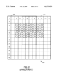
- a pyramid image representation of the image is segmented into M ⁇ N overlapped blocks, and subjected to a variant Wiener filter.
- the size of the blocks and the amount of overlap between blocks can be selected to meet whatever design criteria is specified. In this case, filtering of each overlapped block yields a 4 ⁇ 4 section of filtered pixels for each block as shown by the crosshatched regions. The remaining 2 pixel wide perimeter of each 8 ⁇ 8 block is discarded.
- each overlapped block at each pyramid level is independently filtered with one of many predetermined variant Wiener filters, which may result in the appearance of unacceptable blocking artifacts along the borders of adjacent blocks.
- U.S. Pat. No. 5,454,051 issued Sept. 26, 1995 to Smith discloses a method of reducing blocking artifacts created by block transform compression algorithms by applying a variable lowpass filter (blur) operation on block boundaries that is based on the frequency coefficients of the transformed data.
- a variable lowpass filter blue
- his method is applicable only to unoverlapped blocks.
- his method processes each side of a block individually.
- his corrections are determined only in the frequency domain.
- his method uses a two point filter limited to blurring only boundary pixels.
- the primary object of the present invention is to overcome the above and other problems by providing an improved method and system for removing or at least minimizing blocking artifacts in an image subsequent to independent processing of each block.
- true pixel correction values are calculated, then added to each pixel of the image so that the transition between adjacent blocks of pixels will be smooth.
- This corrective method coined "stitching" can be applied in either the spatial or the frequency domain to each block of filtered pixels in the image and generally includes the steps of;
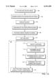
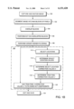
- FIG. 1A is a block diagram of a first variation preferred embodiment of the inventive method applied to a system using variant Wiener noise filtering;
- FIG. 1B is a block diagram of a second variation preferred embodiment of the inventive method applied to a system using variant Wiener noise filtering
- FIG. 2 is a diagrammatic representation of two overlapped 8 ⁇ 8 blocks of image data
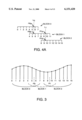
- FIG. 3 is a graphical representation of a sixteen point one-dimensional segment of an image
- FIG. 4A is a graphical representation of the sixteen point one-dimensional segment of FIG. 3 broken into three 8-point blocks with a four point overlap;
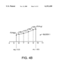
- FIG. 4B is a graphical representation of the measurement point correction values ⁇ and true pixel correction values a featured in an 8 point image segment;
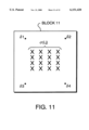
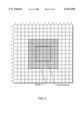
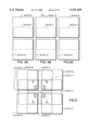
- FIG. 5 is a diagrammatic representation showing the saved and discarded regions of an 8 ⁇ 8 pixel block 11 in a 16 ⁇ 16 pixel image segment;
- FIG. 6 is a diagrammatic representation of all of the 8 ⁇ 8 pixel blocks which overlap block 11 in the image segment of FIG. 5;
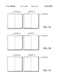
- FIGS. 7A, 7B and 7C illustrate horizontal overlapping of blocks from FIG. 6;
- FIGS. 8A, 8B and 8C illustrate vertical overlapping of blocks from FIG. 6;
- FIG. 9 illustrates overlapping of all the blocks of FIG. 6 in both the horizontal and vertical directions;
- FIG. 10 is an expansion of the drawing of FIG. 5 showing the selected locations used with the inventive method
- FIG. 11 is a graphical representation of the measurement point correction values and the true pixel correction values ⁇ featured in an 8 ⁇ 8 point image segment labeled block 11;
- FIG. 12A is an illustration of a general purpose computer used to implement the inventive stitching method of FIGS. 1A and 1B programmed therein;
- FIG. 12B is a block diagram of selected parts of the system of FIG. 12A necessary to implement the stitching method.
- the inventive stitching method is applied to blocks of pixels which have been subjected to the variant Wiener filtering of U.S. patent application Ser. No. 08/440,639 as shown in FIG. 1.
- the inventive stitching method eliminates or at least minimizes blocking artifacts which occurs from independent processing of each block in an image.
- a one-dimensional image such as the 16 point segment shown in FIG. 3, is captured and digitized in step 100.
- Block 0 consists of points 0-7
- block 1 consists of points 4-11
- block 2 consists of points 8-15.
- M ⁇ N blocks of discrete cosine transform (DCT) coefficients corresponding to the M ⁇ N blocks of pixels are generated in step 106 by performing a DCT on the overlapped blocks of pixels.
- DCT discrete cosine transform
- Variant Wiener filtering of each block of DCT coefficients is performed in step 108 to generate corresponding blocks of filtered DCT coefficients. Further details of the variant Wiener filtering method are outlined in the inventors' earlier filed U.S. patent application Ser. No. 08/440,639 incorporated herein by reference in its entirety. Of course, the use of a variant Wiener filter is illustrated only as one preferred embodiment. It is not necessary in the operation of the inventive stitching method. Any independently filtered blocks of image data resident in either the spatial or frequency domain can be input into the inventive stitching routine 125.
- the next step in the variant Wiener filtering method is to generate inverse discrete cosine transform (IDCT) coefficients in block 110 by taking an IDCT of the blocks of filtered DCT coefficients, then saving selected portions of the inverted blocks, i.e. the saved region, corresponding to the pixels which have been filtered.
- IDCT inverse discrete cosine transform
- the saved IDCT coefficients are then sent to a display or other output device for reproduction of the original image which has been filtered.
- the reproduced image could possibly exhibit blocking artifacts due to the independent application in the variant Wiener filtering method of various filters to the many blocks of the segmented image.
- step 112 measurement points are chosen according to the amount of overlap desired.
- the blocks have been previously filtered, saving the central four pixels and discarding a two pixel wide perimeter for each block.
- the measurement points are defined as preselected points within a block where measurement point correction values will be determined.
- the measurement point may be chosen to fall on a pixel, whereupon measurement point values can be directly measured. More typically, however, the measurement points are chosen to fall between pixels so that the measurement point values are determined by approximation from neighboring pixels using any known approximation method (such as bilinear interpolation of neighboring pixel values).
- the measurement points are chosen to fall between pixels so that the measurement point values are determined by approximation from neighboring pixels using any known approximation method (such as bilinear interpolation of neighboring pixel values).
- m 0 and m 1 two calculations are made in step 114--one calculation for each block overlapping each measurement point.
- Block 0 overlaps block 1 at points 4, 5, 6, 7 and block 2 overlaps block 1 at 8, 9, 10, 11.
- measurement point m 0 is m 0a in block 0 and m 0b in block 1.
- measurement point m 1 is m 1a in block 1 and m 1b in block 2.
- the measurement points for the stitching method must be chosen to be conterminous between adjacent blocks. In the present case, measurement point m 0 is located at 5.5 for both blocks 0 and 1 and measurement point m 1 is located at 9.5 for both blocks 1 and 2.
- Each calculation of a measurement point value can generally be made by either direct measurement, if the measurement point is chosen on a pixel, or by interpolation or other known estimation techniques if the measurement point is chosen to fall between pixels.
- the measurement point value m 0a corresponding to block 0 along line L 0 can be determined by interpolation from neighboring pixels, such as pixels 5 and 6 in block 0.
- the measurement point value m 0b corresponding to block 1 along line L 0 is similarly determined by interpolating values of pixels 5 and 6 in block 1.
- a measurement point value m 1a is determined corresponding to block 1
- a measurement point value m 1b is determined corresponding to block 2. Similar calculations occur for each block of the image.
- the accumulation of measurement point values throughout the image can be arranged in corresponding arrays
- Measurement point correction values ⁇ (m a ) and ⁇ (m b ) are next calculated in step 116 for each measurement point m 0 , m 1 and stored in arrays so that
- ⁇ (m 0a ) represents the measurement point correction value associated with block 0 at m 0
- ⁇ (m 0b ) represents the measurement point correction value associated with block 1 at m 0 (see FIGS. 4A and 4B).
- ⁇ (m 1a ) represents the measurement point correction value associated with block 1 at m 1
- ⁇ (m 1b ) represents the measurement point correction value associated with block 2 at m 1 .
- ⁇ (m 1a ) and ⁇ (m 1b ) relating to a particular measurement point have equal magnitude and opposite signs.
- a second set of correction values termed the true pixel correction values
- the true pixel correction values are designated as ⁇ (i) and are calculated in step 118, i being an integer ranging from 6 to 9.
- true pixel correction values at every pixel in a block can be calculated if desired.
- the true pixel correction values ⁇ (i) for pixels located within the saved region of block 1, are estimated by interpolation from the surrounding measurement point correction values ⁇ (m 0b ) and ⁇ (m 1a ). Any known interpolation method can be applied.
- the true pixel correction values ⁇ (i) have been determined for each pixel of interest, then the true pixel correction values ⁇ (i) are added in step 120 to the respective IDCT coefficients which have been determined and saved in step 110.
- the resulting output from step 120 is a final set of pixels which represents the filtered image free from blocking artifacts.
- FIG. 1B is identical to FIG. 1A except that in FIG. 1B the stitching routine is applied in the DCT domain, and the IDCT step 124 converts the results back into the spatial domain.
- the above-described one-dimensional application of stitching can also be readily extended towards removing blocking artifacts in multiple dimensions.
- the following example of a preferred stitching method is applied to the 16 ⁇ 16 pixel image segment that is shown in FIG. 5.
- the one-dimensional image segment (block 1 as shown in FIG. 4 and described in the above example) is replaced with the two-dimensional image segment block 11 shown in FIG. 5.
- the saved region of pixels ⁇ 6, 7, 8, 9 ⁇ in the one-dimensional example is replaced in the two-dimensional example with a saved region where both x and y are evaluated at integer pixel values of ⁇ 6, 7, 8, 9 ⁇ .
- Block 11 will be overlapped during the filtering process of step 108 (see FIG. 1) in each direction by adjacent 8 ⁇ 8 blocks of pixels.
- the breakdown of all the blocks involved in the processing of block 11 is shown in FIG. 6.
- Each one of blocks 00, 10, 20, 01, 21, 02, 12, and 22 will overlap block 11.
- FIGS. 7A-7C illustrate the horizontal overlapping involved in the current example whereas FIGS. 8A-8C illustrate the vertical overlapping.
- FIG. 7A shows the horizontal overlapping of blocks 00, 10 and 20;
- FIG. 7B shows the horizontal overlapping of blocks 01, 11 and 21;
- FIG. 7C shows the horizontal overlapping of blocks 02, 12 and 22.
- FIG. 8A shows the vertical overlapping of blocks 00, 01 and 02;
- FIG. 8B shows the vertical overlapping of blocks 10, 11 and 12; and FIG. 8C shows the vertical overlapping of blocks 20, 21 and 22.
- the complete overlapping scheme relating to block 11 is shown in FIG. 9. Note that the pixels located in the saved region are indicated by Xs. After processing is finished for block 11, the pixels in the saved region may be modified (i.e. corrected) to prevent blocking artifacts. The modification of these pixels will be explained hereafter.
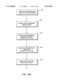
- the stitching method 125 begins in step 112 where measurement points are chosen according to the amount of overlap desired.
- the two pixel wide perimeter of image data points will be discarded, i.e. points within block 11 that are not included within the saved region.
- measurement points are chosen so that the corrections to measurement point values can be used to estimate the true pixel correction values corresponding to each pixel within the saved region. In this case (see FIG.
- the four measurement point values each relate to one of the four overlapping 8 ⁇ 8 pixel blocks which affects that particular measurement point.
- Measurement point values are determined for all adjacent overlapping blocks at measurement points throughout the image.
- the accumulation of measurement point values from all the blocks in the image can be arranged in corresponding arrays
- Measurement point correction values ⁇ a , ⁇ b , ⁇ c and ⁇ d are next calculated in step 116 for each corresponding measurement point value m a , m b , m c , m d , respectively, at each measurement point.
- the true pixel correction values ⁇ (i,j) corresponding to the pixels in the saved region of block 11 can be determined in step 118 by interpolation of the known measurement point correction values of equations (4) through (7).
- the true pixel correction values for each pixel in the saved region (marked by Xs) of block 11, are evaluated in a like manner as earlier described for the one-dimensional example.
- These true pixel correction values ⁇ (i,j) are, respectively, added in step 120 to the IDCT coefficients of pixels in the saved region so that the processed image can be viewed or otherwise displayed without any blocking artifacts.
- the inventive stitching method for removing or at least minimizing blocking artifacts in a filtered image can occur in either the spatial or the frequency domain.
- the inputs and the outputs for processing can reside in either the spatial or frequency domain.
- a spatial domain input can result in either a spatial or frequency domain output
- a frequency domain input can also result in either a spatial or frequency domain output.
- the size of the blocks, the amount of overlap between adjacent blocks, and the indexing of pixels within the blocks can all be varied to conform with acceptable design and application requirements.
- One workable system for implementing the above stitching method is a general purpose computer 310 as shown in FIG. 12A.
- Selected parts of the computer 310, necessary for programming the stitching method into the computer, are shown in FIG. 12B to include: means for determining measurement point values 300; means for determining mean values 302; means for determining measurement point correction values 304; means for determining true pixel correction values 306; and means for adjusting true pixel values 308.
- the determination of measurement points can be made manually, by operator input, or automatically according to software requirements for a specific application.
- Each of the components shown in FIG. 12B could, for instance, be resident in the central processing unit of the computer.
Abstract
Description
δ.sub.1a =M.sub.1 -m.sub.1a (4)
δ.sub.1b =M.sub.1 -m.sub.1b (5)
δ.sub.1c =M.sub.1 -m.sub.1c (6)
δ.sub.1d =M.sub.1 -m.sub.1d (7)
Claims (14)
Priority Applications (6)
| Application Number | Priority Date | Filing Date | Title |
|---|---|---|---|
| US08/573,504 US6151420A (en) | 1995-12-15 | 1995-12-15 | Minimizing blocking artifacts in a filtered image |
| KR1019970703690A KR100305190B1 (en) | 1995-12-15 | 1996-06-13 | Apparatus and Method for Minimizing Blocking in Filtered Images |
| EP96918498A EP0809834A2 (en) | 1995-12-15 | 1996-06-13 | System and method for minimizing blocking artifacts in a filtered image |
| JP52275397A JP2001509971A (en) | 1995-12-15 | 1996-06-13 | Method and apparatus for minimizing interference products in filtered images |
| CA002207722A CA2207722A1 (en) | 1995-12-15 | 1996-06-13 | System and method for minimizing blocking artifacts in a filtered image |
| PCT/US1996/010364 WO1997022948A2 (en) | 1995-12-15 | 1996-06-13 | System and method for minimizing blocking artifacts in a filtered image |
Applications Claiming Priority (1)
| Application Number | Priority Date | Filing Date | Title |
|---|---|---|---|
| US08/573,504 US6151420A (en) | 1995-12-15 | 1995-12-15 | Minimizing blocking artifacts in a filtered image |
Publications (1)
| Publication Number | Publication Date |
|---|---|
| US6151420A true US6151420A (en) | 2000-11-21 |
Family
ID=24292255
Family Applications (1)
| Application Number | Title | Priority Date | Filing Date |
|---|---|---|---|
| US08/573,504 Expired - Lifetime US6151420A (en) | 1995-12-15 | 1995-12-15 | Minimizing blocking artifacts in a filtered image |
Country Status (6)
| Country | Link |
|---|---|
| US (1) | US6151420A (en) |
| EP (1) | EP0809834A2 (en) |
| JP (1) | JP2001509971A (en) |
| KR (1) | KR100305190B1 (en) |
| CA (1) | CA2207722A1 (en) |
| WO (1) | WO1997022948A2 (en) |
Cited By (27)
| Publication number | Priority date | Publication date | Assignee | Title |
|---|---|---|---|---|
| US20020118887A1 (en) * | 2000-12-20 | 2002-08-29 | Eastman Kodak Company | Multiresolution based method for removing noise from digital images |
| US20030044080A1 (en) * | 2001-09-05 | 2003-03-06 | Emblaze Systems Ltd | Method for reducing blocking artifacts |
| US20030053711A1 (en) * | 2001-09-20 | 2003-03-20 | Changick Kim | Reducing blocking and ringing artifacts in low-bit-rate coding |
| US20030053708A1 (en) * | 2001-07-02 | 2003-03-20 | Jasc Software | Removal of block encoding artifacts |
| US20030190086A1 (en) * | 2002-04-05 | 2003-10-09 | Changick Kim | Adaptive post-filtering for reducing noise in highly compressed image/video coding |
| US6636645B1 (en) * | 2000-06-29 | 2003-10-21 | Eastman Kodak Company | Image processing method for reducing noise and blocking artifact in a digital image |
| US20030228067A1 (en) * | 2002-06-05 | 2003-12-11 | Canon Kabushiki Kaisha | Image processing apparatus, image processing method, and computer program |
| US20030228064A1 (en) * | 2002-06-06 | 2003-12-11 | Eastman Kodak Company | Multiresolution method of spatially filtering a digital image |
| US20030235248A1 (en) * | 2002-06-21 | 2003-12-25 | Changick Kim | Hybrid technique for reducing blocking and ringing artifacts in low-bit-rate coding |
| US6707952B1 (en) * | 2000-05-30 | 2004-03-16 | Sharp Laboratories Of America, Inc. | Method for removing ringing artifacts from locations near dominant edges of an image reconstructed after compression |
| US20040057631A1 (en) * | 2002-09-20 | 2004-03-25 | Changick Kim | Method and apparatus for video deblocking |
| US20040184669A1 (en) * | 2000-05-30 | 2004-09-23 | Yap-Peng Tan | Method for removing ringing artifacts from locations near dominant edges of an image reconstructed after compression |
| US20050007375A1 (en) * | 2003-07-09 | 2005-01-13 | Samsung Electronics Co., Ltd | Seamless image processing method and apparatus |
| US20060133679A1 (en) * | 2004-12-21 | 2006-06-22 | Konica Minolta Business Technologies, Inc. | Data processing device capable of processing image data with small memory capacity, image processing method, and program product |
| US20060282783A1 (en) * | 2005-06-10 | 2006-12-14 | Michele Covell | Method and system for enhancing the quality of video prompts in an interactive media response system |
| US20070122052A1 (en) * | 1997-07-30 | 2007-05-31 | Lg Electronics Inc. | Method of reducing a blocking artifact when coding moving picture |
| US20070122054A1 (en) * | 1997-07-30 | 2007-05-31 | Lg Electronics Inc. | Method of reducing a blocking artifact when coding moving picture |
| US20090022418A1 (en) * | 2005-10-06 | 2009-01-22 | Vvond, Llc | Minimizing blocking artifacts in videos |
| US7542590B1 (en) | 2004-05-07 | 2009-06-02 | Yt Acquisition Corporation | System and method for upgrading biometric data |
| US7616829B1 (en) | 2003-10-29 | 2009-11-10 | Apple Inc. | Reducing undesirable block based image processing artifacts by DC image filtering |
| US20100033633A1 (en) * | 2006-12-28 | 2010-02-11 | Gokce Dane | Detecting block artifacts in coded images and video |
| USRE42516E1 (en) | 1997-09-09 | 2011-07-05 | Video Enhancement Solutions, LLC | Method of removing blocking artifacts in a coding system of a moving picture |
| US20120287989A1 (en) * | 2011-05-13 | 2012-11-15 | Madhukar Budagavi | Inverse Transformation Using Pruning For Video Coding |
| US20130329999A1 (en) * | 2012-06-08 | 2013-12-12 | Panasonic Corporation | Image processor, image processing method, image processing program, and chip circuit |
| US20140037228A1 (en) * | 2012-08-03 | 2014-02-06 | Siemens Corporation | Zero communication block partitioning |
| CN107240070A (en) * | 2017-06-08 | 2017-10-10 | 广东容祺智能科技有限公司 | A kind of unmanned plane image mosaic system and method based on emergency processing |
| CN116452465A (en) * | 2023-06-13 | 2023-07-18 | 江苏游隼微电子有限公司 | Method for eliminating JPEG image block artifact |
Families Citing this family (2)
| Publication number | Priority date | Publication date | Assignee | Title |
|---|---|---|---|---|
| KR100973964B1 (en) | 2009-11-13 | 2010-08-05 | 재단법인대구경북과학기술원 | Method and apparatus for parallel box filtering in rigion based image processing |
| CN103489170B (en) * | 2013-09-05 | 2017-01-11 | 浙江宇视科技有限公司 | Method and device for JPEG picture synthesis and OSD information superimposition |
Citations (6)
| Publication number | Priority date | Publication date | Assignee | Title |
|---|---|---|---|---|
| US5168375A (en) * | 1991-09-18 | 1992-12-01 | Polaroid Corporation | Image reconstruction by use of discrete cosine and related transforms |
| US5235434A (en) * | 1991-06-27 | 1993-08-10 | Polaroid Corporation | Method and apparatus for selectively adjusting the brightness of large regions of an image |
| US5454051A (en) * | 1991-08-05 | 1995-09-26 | Eastman Kodak Company | Method of reducing block artifacts created by block transform compression algorithms |
| US5563718A (en) * | 1993-11-30 | 1996-10-08 | Polaroid Corporation | Image coding by use of discrete cosine transforms |
| US5729631A (en) * | 1993-11-30 | 1998-03-17 | Polaroid Corporation | Image noise reduction system using a wiener variant filter in a pyramid image representation |
| US5740284A (en) * | 1993-11-30 | 1998-04-14 | Polaroid Corporation | Coding method and apparatus for resampling and filtering images using discrete cosine transforms |
Family Cites Families (3)
| Publication number | Priority date | Publication date | Assignee | Title |
|---|---|---|---|---|
| US5022085A (en) * | 1990-05-29 | 1991-06-04 | Eastman Kodak Company | Neighborhood-based merging of image data |
| US5367385A (en) * | 1992-05-07 | 1994-11-22 | Picturetel Corporation | Method and apparatus for processing block coded image data to reduce boundary artifacts between adjacent image blocks |
| JP3466705B2 (en) * | 1993-05-28 | 2003-11-17 | ゼロックス・コーポレーション | How to decompress compressed images |
-
1995
- 1995-12-15 US US08/573,504 patent/US6151420A/en not_active Expired - Lifetime
-
1996
- 1996-06-13 KR KR1019970703690A patent/KR100305190B1/en not_active IP Right Cessation
- 1996-06-13 CA CA002207722A patent/CA2207722A1/en not_active Abandoned
- 1996-06-13 JP JP52275397A patent/JP2001509971A/en active Pending
- 1996-06-13 EP EP96918498A patent/EP0809834A2/en not_active Withdrawn
- 1996-06-13 WO PCT/US1996/010364 patent/WO1997022948A2/en not_active Application Discontinuation
Patent Citations (6)
| Publication number | Priority date | Publication date | Assignee | Title |
|---|---|---|---|---|
| US5235434A (en) * | 1991-06-27 | 1993-08-10 | Polaroid Corporation | Method and apparatus for selectively adjusting the brightness of large regions of an image |
| US5454051A (en) * | 1991-08-05 | 1995-09-26 | Eastman Kodak Company | Method of reducing block artifacts created by block transform compression algorithms |
| US5168375A (en) * | 1991-09-18 | 1992-12-01 | Polaroid Corporation | Image reconstruction by use of discrete cosine and related transforms |
| US5563718A (en) * | 1993-11-30 | 1996-10-08 | Polaroid Corporation | Image coding by use of discrete cosine transforms |
| US5729631A (en) * | 1993-11-30 | 1998-03-17 | Polaroid Corporation | Image noise reduction system using a wiener variant filter in a pyramid image representation |
| US5740284A (en) * | 1993-11-30 | 1998-04-14 | Polaroid Corporation | Coding method and apparatus for resampling and filtering images using discrete cosine transforms |
Non-Patent Citations (3)
| Title |
|---|
| Hajjahmad et al.; U.S. Patent Application No. 08/441,383. * |
| Wober et al.; U.S. Patent Application No. 08/427,457. * |
| Wober et al.; U.S. Patent Application No. 08/440,639. * |
Cited By (124)
| Publication number | Priority date | Publication date | Assignee | Title |
|---|---|---|---|---|
| US7394945B2 (en) | 1997-07-30 | 2008-07-01 | Lg Electronics Inc. | Method of reducing a blocking artifact when coding moving picture |
| US20080193041A1 (en) * | 1997-07-30 | 2008-08-14 | Lg Electronics Inc. | Method of reducing a blocking artifact when coding moving picture |
| US7391924B2 (en) | 1997-07-30 | 2008-06-24 | Lg Electronics Inc. | Method of reducing a blocking artifact when coding moving picture |
| US9456221B2 (en) | 1997-07-30 | 2016-09-27 | Lg Electronics Inc. | Method of reducing a blocking artifact when coding moving picture |
| US8983225B2 (en) * | 1997-07-30 | 2015-03-17 | Lg Electronics Inc. | Method of reducing a blocking artifact when coding moving picture |
| US20100086058A1 (en) * | 1997-07-30 | 2010-04-08 | Video Enhancement Solutions LLC | Method of reducing a blocking artifact when coding moving picture |
| US7620262B2 (en) | 1997-07-30 | 2009-11-17 | Video Enhancement Solutions LLC | Method of reducing a blocking artifact when coding moving picture |
| US7616832B2 (en) | 1997-07-30 | 2009-11-10 | Video Enhancement Solutions LLC | Method of reducing a blocking artifact when coding moving picture |
| US7616831B2 (en) | 1997-07-30 | 2009-11-10 | Video Enhancement Solutions | Method of reducing a blocking artifact when coding moving picture |
| US7616833B2 (en) | 1997-07-30 | 2009-11-10 | Video Enhancement Solutions LLC | Method of reducing a blocking artifact when coding moving picture |
| US7599571B2 (en) | 1997-07-30 | 2009-10-06 | Lg Electronics Inc. | Method of reducing a blocking artifact when coding moving picture |
| US7499598B2 (en) | 1997-07-30 | 2009-03-03 | Lg Electronics Inc. | Method of reducing a blocking artifact when coding moving picture |
| US7496239B2 (en) | 1997-07-30 | 2009-02-24 | Lg Electronics Inc. | Method of reducing a blocking artifact when coding moving picture |
| US7492960B2 (en) | 1997-07-30 | 2009-02-17 | Lg Electronics Inc. | Method of reducing a blocking artifact when coding moving picture |
| US7492959B2 (en) | 1997-07-30 | 2009-02-17 | Lg Electronics Inc. | Method of reducing a blocking artifact when coding moving picture |
| US7492961B2 (en) | 1997-07-30 | 2009-02-17 | Lg Electronics Inc. | Method of reducing a blocking artifact when coding moving picture |
| US7463786B2 (en) | 1997-07-30 | 2008-12-09 | Lg Electronics Inc. | Method of reducing a blocking artifact when coding moving picture |
| US7454082B2 (en) | 1997-07-30 | 2008-11-18 | Lg Electronics Inc. | Method of reducing a blocking artifact when coding moving picture |
| US7437015B2 (en) | 1997-07-30 | 2008-10-14 | Lg Electronics Inc. | Method of reducing a blocking artifact when coding moving picture |
| US20080212686A1 (en) * | 1997-07-30 | 2008-09-04 | Lg Electronics Inc. | Method of reducing a blocking artifact when coding moving picture |
| US20080193040A1 (en) * | 1997-07-30 | 2008-08-14 | Lg Electronics Inc. | Method of reducing a blocking artifact when coding moving picture |
| US20070122052A1 (en) * | 1997-07-30 | 2007-05-31 | Lg Electronics Inc. | Method of reducing a blocking artifact when coding moving picture |
| US20070122054A1 (en) * | 1997-07-30 | 2007-05-31 | Lg Electronics Inc. | Method of reducing a blocking artifact when coding moving picture |
| US20070122055A1 (en) * | 1997-07-30 | 2007-05-31 | Lg Electronics, Inc. | Method of Reducing a Blocking Artifact When Coding Moving Picture |
| US20070133897A1 (en) * | 1997-07-30 | 2007-06-14 | Lg Electronics Inc. | Method of reducing a blocking artifact when coding moving picture |
| US20070140585A1 (en) * | 1997-07-30 | 2007-06-21 | Lg Electronics Inc. | Method of reducing a blocking artifact when coding moving picture |
| US20070140586A1 (en) * | 1997-07-30 | 2007-06-21 | Lg Electronics Inc. | Method of reducing a blocking artifact when coding moving picture |
| US20070140584A1 (en) * | 1997-07-30 | 2007-06-21 | Lg Electronics Inc. | Method of reducing a blocking artifact when coding moving picture |
| US7262886B2 (en) | 1997-07-30 | 2007-08-28 | Lg Electronics Inc. | Method of reducing a blocking artifact when coding moving picture |
| US7277593B2 (en) * | 1997-07-30 | 2007-10-02 | Lg Electronics Inc. | Method of reducing a blocking artifact when coding moving picture |
| US7283681B2 (en) | 1997-07-30 | 2007-10-16 | Lg Electronics Inc. | Method of reducing a blocking artifact when coding moving picture |
| US7283682B2 (en) | 1997-07-30 | 2007-10-16 | Lg Electronics Inc. | Method of reducing a blocking artifact when coding moving picture |
| US20070248168A1 (en) * | 1997-07-30 | 2007-10-25 | Lg Electronics Inc. | Method of reducing a blocking artifact when coding moving picture |
| US7289682B2 (en) * | 1997-07-30 | 2007-10-30 | Lg Electronics Inc. | Method of reducing a blocking artifact when coding moving picture |
| US20070268969A1 (en) * | 1997-07-30 | 2007-11-22 | Lg Electronics Inc. | Method of reducing a blocking artifact when coding moving picture |
| US20070268970A1 (en) * | 1997-07-30 | 2007-11-22 | Lg Electronics Inc. | Method of reducing a blocking artifact when coding moving picture |
| US7305143B2 (en) | 1997-07-30 | 2007-12-04 | Lg Electronics Inc. | Method of reducing a blocking artifact when coding moving picture |
| US7305142B2 (en) | 1997-07-30 | 2007-12-04 | Lg Electronics Inc. | Method of reducing a blocking artifact when coding moving picture |
| US20070280553A1 (en) * | 1997-07-30 | 2007-12-06 | Lg Electronics Inc. | Method of reducing a blocking artifact when coding moving picture |
| US20070292043A1 (en) * | 1997-07-30 | 2007-12-20 | Lg Electronics Inc. | Method of reducing a blocking artifact when coding moving picture |
| US20080019442A1 (en) * | 1997-07-30 | 2008-01-24 | Lg Electronics Inc. | Method of reducing a blocking artifact when coding moving picture |
| US20080037625A1 (en) * | 1997-07-30 | 2008-02-14 | Lg Electronics Inc. | Method of reducing a blocking artifact when coding moving picture |
| US20080037629A1 (en) * | 1997-07-30 | 2008-02-14 | Lg Electronics Inc. | Method of reducing a blocking artifact when coding moving picture |
| US20080037638A1 (en) * | 1997-07-30 | 2008-02-14 | Lg Electronics Inc. | Method of reducing a blocking artifact when coding moving picture |
| US20080037634A1 (en) * | 1997-07-30 | 2008-02-14 | Lg Electronics Inc. | Method of reducing a blocking artifact when coding moving picture |
| US20080037894A1 (en) * | 1997-07-30 | 2008-02-14 | Lg Electronics Inc. | Method of reducing a blocking artifact when coding moving picture |
| US20080043854A1 (en) * | 1997-07-30 | 2008-02-21 | Lg Electronics Inc. | Method of reducing a blocking artifact when coding moving picture |
| US20080043838A1 (en) * | 1997-07-30 | 2008-02-21 | Lg Electronics Inc. | Method of reducing a blocking artifact when coding moving picture |
| US20080043837A1 (en) * | 1997-07-30 | 2008-02-21 | Lg Electronics Inc. | Method of reducing a blocking artifact when coding moving picture |
| US20080069472A1 (en) * | 1997-07-30 | 2008-03-20 | Lg Electronics Inc. | Method of reducing a blocking artifact when coding moving picture |
| US20080069222A1 (en) * | 1997-07-30 | 2008-03-20 | Lg Electronics Inc. | Method of reducing a blocking artifact when coding moving picture |
| US7391922B2 (en) | 1997-07-30 | 2008-06-24 | Lg Electronics Inc. | Method of reducing a blocking artifact when coding moving picture |
| US7359569B2 (en) | 1997-07-30 | 2008-04-15 | Lg Electronics Inc. | Method of reducing a blocking artifact when coding moving picture |
| US7362913B2 (en) | 1997-07-30 | 2008-04-22 | Lg Electronics Inc. | Method of reducing a blocking artifact when coding moving picture |
| US7362914B2 (en) | 1997-07-30 | 2008-04-22 | Lg Electronics Inc. | Method of reducing a blocking artifact when coding moving picture |
| US7379617B2 (en) | 1997-07-30 | 2008-05-27 | Lg Electronics Inc. | Method of reducing a blocking artifact when coding moving picture |
| US7379616B2 (en) | 1997-07-30 | 2008-05-27 | Lg Electronics Inc. | Method of reducing a blocking artifact when coding moving picture |
| US7382930B2 (en) | 1997-07-30 | 2008-06-03 | Lg Electronics Inc. | Method of reducing a blocking artifact when coding moving picture |
| US7391923B2 (en) | 1997-07-30 | 2008-06-24 | Lg Electronics Inc. | Method of reducing a blocking artifact when coding moving picture |
| US7391921B2 (en) | 1997-07-30 | 2008-06-24 | Lg Electronics Inc. | Method of reducing a blocking artifact when coding moving picture |
| US20080193038A1 (en) * | 1997-07-30 | 2008-08-14 | Lg Electronics Inc. | Method of reducing a blocking artifact when coding moving picture |
| US7359570B2 (en) | 1997-07-30 | 2008-04-15 | Lg Electronics Inc. | Method of reducing a blocking artifact when coding moving picture |
| US20080193039A1 (en) * | 1997-07-30 | 2008-08-14 | Lg Electronics Inc. | Method of reducing a blocking artifact when coding moving picture |
| US7397965B2 (en) | 1997-07-30 | 2008-07-08 | Lg Electronics Inc. | Method of reducing a blocking artifact when coding moving picture |
| US7397966B2 (en) | 1997-07-30 | 2008-07-08 | Lg Electronics Inc. | Method of reducing a blocking artifact when coding moving picture |
| US7397967B2 (en) | 1997-07-30 | 2008-07-08 | Lg Electronics Inc. | Method of reducing a blocking artifact when coding moving picture |
| US7400780B2 (en) | 1997-07-30 | 2008-07-15 | Lg Electronics Inc. | Method of reducing a blocking artifact when coding moving picture |
| US7403667B2 (en) | 1997-07-30 | 2008-07-22 | Lg Electronics Inc. | Method of reducing a blocking artifact when coding moving picture |
| US7406209B2 (en) | 1997-07-30 | 2008-07-29 | Lg Electronics Inc. | Method of reducing a blocking artifact when coding moving picture |
| US20080192829A1 (en) * | 1997-07-30 | 2008-08-14 | Lg Electronics Inc. | Method of reducing a blocking artifact when coding moving picture |
| USRE42851E1 (en) | 1997-09-09 | 2011-10-18 | Video Enhancement Solutions LLC | Method of removing blocking artifacts in a coding system of a moving picture |
| USRE42516E1 (en) | 1997-09-09 | 2011-07-05 | Video Enhancement Solutions, LLC | Method of removing blocking artifacts in a coding system of a moving picture |
| USRE42660E1 (en) | 1997-09-09 | 2011-08-30 | Video Enhancement Solutions LLC | Method of removing blocking artifacts in a coding system of a moving picture |
| USRE42693E1 (en) | 1997-09-09 | 2011-09-13 | Video Enhancement Solutions LLC | Method of removing blocking artifacts in a coding system of a moving picture |
| USRE42713E1 (en) | 1997-09-09 | 2011-09-20 | Video Enhancement Solutions LLC | Method of removing blocking artifacts in a coding system of a moving picture |
| US6707952B1 (en) * | 2000-05-30 | 2004-03-16 | Sharp Laboratories Of America, Inc. | Method for removing ringing artifacts from locations near dominant edges of an image reconstructed after compression |
| US7440635B2 (en) | 2000-05-30 | 2008-10-21 | Sharp Laboratories Of America, Inc. | Method for removing ringing artifacts from locations near dominant edges of an image reconstructed after compression |
| US20040184669A1 (en) * | 2000-05-30 | 2004-09-23 | Yap-Peng Tan | Method for removing ringing artifacts from locations near dominant edges of an image reconstructed after compression |
| US6636645B1 (en) * | 2000-06-29 | 2003-10-21 | Eastman Kodak Company | Image processing method for reducing noise and blocking artifact in a digital image |
| US20020118887A1 (en) * | 2000-12-20 | 2002-08-29 | Eastman Kodak Company | Multiresolution based method for removing noise from digital images |
| US6937772B2 (en) * | 2000-12-20 | 2005-08-30 | Eastman Kodak Company | Multiresolution based method for removing noise from digital images |
| US7003174B2 (en) | 2001-07-02 | 2006-02-21 | Corel Corporation | Removal of block encoding artifacts |
| US20030053708A1 (en) * | 2001-07-02 | 2003-03-20 | Jasc Software | Removal of block encoding artifacts |
| US7426315B2 (en) | 2001-09-05 | 2008-09-16 | Zoran Microelectronics Ltd. | Method for reducing blocking artifacts |
| US20090028459A1 (en) * | 2001-09-05 | 2009-01-29 | Zoran Corporation | Method for reducing blocking artifacts |
| US20030044080A1 (en) * | 2001-09-05 | 2003-03-06 | Emblaze Systems Ltd | Method for reducing blocking artifacts |
| US7706627B2 (en) | 2001-09-05 | 2010-04-27 | Zoran Corporation | Method for reducing blocking artifacts |
| US20030053711A1 (en) * | 2001-09-20 | 2003-03-20 | Changick Kim | Reducing blocking and ringing artifacts in low-bit-rate coding |
| US20030190086A1 (en) * | 2002-04-05 | 2003-10-09 | Changick Kim | Adaptive post-filtering for reducing noise in highly compressed image/video coding |
| US7031552B2 (en) | 2002-04-05 | 2006-04-18 | Seiko Epson Corporation | Adaptive post-filtering for reducing noise in highly compressed image/video coding |
| US8306357B2 (en) | 2002-06-05 | 2012-11-06 | Canon Kabushiki Kaisha | Image processing apparatus, image processing method, and computer program |
| US8023764B2 (en) * | 2002-06-05 | 2011-09-20 | Canon Kabushiki Kaisha | Image processing apparatus, image processing method, and a program, for removing low-frequency noise from image data |
| US20030228067A1 (en) * | 2002-06-05 | 2003-12-11 | Canon Kabushiki Kaisha | Image processing apparatus, image processing method, and computer program |
| US8744209B2 (en) | 2002-06-05 | 2014-06-03 | Canon Kabushiki Kaisha | Image processing apparatus and image processing method for visually reducing noise components contained in a low frequency range of image data |
| US7181086B2 (en) * | 2002-06-06 | 2007-02-20 | Eastman Kodak Company | Multiresolution method of spatially filtering a digital image |
| US20030228064A1 (en) * | 2002-06-06 | 2003-12-11 | Eastman Kodak Company | Multiresolution method of spatially filtering a digital image |
| US20030235248A1 (en) * | 2002-06-21 | 2003-12-25 | Changick Kim | Hybrid technique for reducing blocking and ringing artifacts in low-bit-rate coding |
| US6950473B2 (en) | 2002-06-21 | 2005-09-27 | Seiko Epson Corporation | Hybrid technique for reducing blocking and ringing artifacts in low-bit-rate coding |
| US7623577B2 (en) | 2002-09-20 | 2009-11-24 | Seiko Epson Corporation | Method and apparatus for video deblocking |
| US20040057631A1 (en) * | 2002-09-20 | 2004-03-25 | Changick Kim | Method and apparatus for video deblocking |
| US7031392B2 (en) | 2002-09-20 | 2006-04-18 | Seiko Epson Corporation | Method and apparatus for video deblocking |
| US20050007375A1 (en) * | 2003-07-09 | 2005-01-13 | Samsung Electronics Co., Ltd | Seamless image processing method and apparatus |
| US7616829B1 (en) | 2003-10-29 | 2009-11-10 | Apple Inc. | Reducing undesirable block based image processing artifacts by DC image filtering |
| US7542590B1 (en) | 2004-05-07 | 2009-06-02 | Yt Acquisition Corporation | System and method for upgrading biometric data |
| US7529419B2 (en) * | 2004-12-21 | 2009-05-05 | Konica Minolta Business Technologies, Inc. | Data processing device capable of processing image data with small memory capacity, image processing method, and program product |
| US20060133679A1 (en) * | 2004-12-21 | 2006-06-22 | Konica Minolta Business Technologies, Inc. | Data processing device capable of processing image data with small memory capacity, image processing method, and program product |
| US8687016B2 (en) * | 2005-06-10 | 2014-04-01 | Hewlett-Packard Development Company, L.P. | Method and system for enhancing the quality of video prompts in an interactive media response system |
| US20060282783A1 (en) * | 2005-06-10 | 2006-12-14 | Michele Covell | Method and system for enhancing the quality of video prompts in an interactive media response system |
| US20090022418A1 (en) * | 2005-10-06 | 2009-01-22 | Vvond, Llc | Minimizing blocking artifacts in videos |
| US8023559B2 (en) * | 2005-10-06 | 2011-09-20 | Vudu, Inc. | Minimizing blocking artifacts in videos |
| US8879001B2 (en) * | 2006-12-28 | 2014-11-04 | Thomson Licensing | Detecting block artifacts in coded images and video |
| US20100033633A1 (en) * | 2006-12-28 | 2010-02-11 | Gokce Dane | Detecting block artifacts in coded images and video |
| US11625452B2 (en) | 2011-05-13 | 2023-04-11 | Texas Instruments Incorporated | Inverse transformation using pruning for video coding |
| US10783217B2 (en) | 2011-05-13 | 2020-09-22 | Texas Instruments Incorporated | Inverse transformation using pruning for video coding |
| US20120287989A1 (en) * | 2011-05-13 | 2012-11-15 | Madhukar Budagavi | Inverse Transformation Using Pruning For Video Coding |
| US9747255B2 (en) * | 2011-05-13 | 2017-08-29 | Texas Instruments Incorporated | Inverse transformation using pruning for video coding |
| US11301543B2 (en) | 2011-05-13 | 2022-04-12 | Texas Instruments Incorporated | Inverse transformation using pruning for video coding |
| US8908965B2 (en) * | 2012-06-08 | 2014-12-09 | Panasonic Corporation | Image processor, image processing method, image processing program, and chip circuit |
| US20130329999A1 (en) * | 2012-06-08 | 2013-12-12 | Panasonic Corporation | Image processor, image processing method, image processing program, and chip circuit |
| US20140037228A1 (en) * | 2012-08-03 | 2014-02-06 | Siemens Corporation | Zero communication block partitioning |
| US9286648B2 (en) * | 2012-08-03 | 2016-03-15 | Nadar Mariappan S | Zero communication block partitioning |
| CN107240070A (en) * | 2017-06-08 | 2017-10-10 | 广东容祺智能科技有限公司 | A kind of unmanned plane image mosaic system and method based on emergency processing |
| CN116452465A (en) * | 2023-06-13 | 2023-07-18 | 江苏游隼微电子有限公司 | Method for eliminating JPEG image block artifact |
| CN116452465B (en) * | 2023-06-13 | 2023-08-11 | 江苏游隼微电子有限公司 | Method for eliminating JPEG image block artifact |
Also Published As
| Publication number | Publication date |
|---|---|
| CA2207722A1 (en) | 1997-06-26 |
| KR100305190B1 (en) | 2001-11-22 |
| WO1997022948A3 (en) | 2000-11-23 |
| EP0809834A2 (en) | 1997-12-03 |
| KR980700783A (en) | 1998-03-30 |
| WO1997022948A2 (en) | 1997-06-26 |
| JP2001509971A (en) | 2001-07-24 |
Similar Documents
| Publication | Publication Date | Title |
|---|---|---|
| US6151420A (en) | Minimizing blocking artifacts in a filtered image | |
| US6456745B1 (en) | Method and apparatus for re-sizing and zooming images by operating directly on their digital transforms | |
| EP1794714B1 (en) | Magnification and pinching of two-dimensional images | |
| US6181376B1 (en) | Method of determining missing color values for pixels in a color filter array | |
| JP3328934B2 (en) | Method and apparatus for fusing images | |
| US6211913B1 (en) | Apparatus and method for removing blank areas from real-time stabilized images by inserting background information | |
| USRE47238E1 (en) | Filtering control method for improving image quality of bi-linear interpolated image | |
| US5185808A (en) | Method for merging images | |
| US6668097B1 (en) | Method and apparatus for the reduction of artifact in decompressed images using morphological post-filtering | |
| JP3465226B2 (en) | Image density conversion processing method | |
| US6496608B1 (en) | Image data interpolation system and method | |
| US7298917B2 (en) | Image processing program product and device for executing Retinex processing | |
| Hong et al. | An edge-preserving image interpolation system for a digital camcorder | |
| EP1292118A2 (en) | Tone scale adjustment of digital images | |
| US20020114532A1 (en) | Method and apparatus for deblurring and re-blurring image segments | |
| US5887084A (en) | Structuring a digital image into a DCT pyramid image representation | |
| US5748792A (en) | Large kernel filtering using a fixed-size block processor | |
| US8208750B2 (en) | Method and system for dual-envelope image enhancement | |
| EP0992942B1 (en) | Method for smoothing staircase effect in enlarged low resolution images | |
| JP2916607B2 (en) | Image magnifier | |
| Lukac | Image Resizing Solutions for Single-Sensor Digital Cameras | |
| Chen et al. | Directional moving averaging interpolation for bilinear texture mapping | |
| JP2005136891A (en) | Image encoding method and apparatus, program, and storage medium with the program stored thereon | |
| JPH03192979A (en) | Display system for picture | |
| Yoo et al. | Real-Time Continuous-Scale Image Interpolation with Directional Smoothing |
Legal Events
| Date | Code | Title | Description |
|---|---|---|---|
| STCF | Information on status: patent grant |
Free format text: PATENTED CASE |
|
| AS | Assignment |
Owner name: MORGAN GUARANTY TRUST COMPANY OF NEW YORK, NEW YOR Free format text: SECURITY AGREEMENT;ASSIGNOR:POLAROID CORPORATION;REEL/FRAME:011658/0699 Effective date: 20010321 |
|
| FPAY | Fee payment |
Year of fee payment: 4 |
|
| AS | Assignment |
Owner name: OEP IMAGINIG OPERATING CORPORATION, NEW YORK Free format text: ASSIGNMENT OF ASSIGNORS INTEREST;ASSIGNOR:POLAROID CORPORATION;REEL/FRAME:016427/0144 Effective date: 20020731 Owner name: POLAROID CORPORATION, NEW YORK Free format text: CHANGE OF NAME;ASSIGNOR:OEP IMAGING OPERATING CORPORATION;REEL/FRAME:016470/0006 Effective date: 20020801 Owner name: OEP IMAGINIG OPERATING CORPORATION,NEW YORK Free format text: ASSIGNMENT OF ASSIGNORS INTEREST;ASSIGNOR:POLAROID CORPORATION;REEL/FRAME:016427/0144 Effective date: 20020731 Owner name: POLAROID CORPORATION,NEW YORK Free format text: CHANGE OF NAME;ASSIGNOR:OEP IMAGING OPERATING CORPORATION;REEL/FRAME:016470/0006 Effective date: 20020801 |
|
| AS | Assignment |
Owner name: WILMINGTON TRUST COMPANY, AS COLLATERAL AGENT, DEL Free format text: ASSIGNMENT OF ASSIGNORS INTEREST;ASSIGNORS:POLAROLD HOLDING COMPANY;POLAROID CORPORATION;POLAROID ASIA PACIFIC LLC;AND OTHERS;REEL/FRAME:016602/0332 Effective date: 20050428 Owner name: JPMORGAN CHASE BANK,N.A,AS ADMINISTRATIVE AGENT, W Free format text: SECURITY INTEREST;ASSIGNORS:POLAROID HOLDING COMPANY;POLAROID CORPORATION;POLAROID ASIA PACIFIC LLC;AND OTHERS;REEL/FRAME:016602/0603 Effective date: 20050428 Owner name: WILMINGTON TRUST COMPANY, AS COLLATERAL AGENT,DELA Free format text: SECURITY AGREEMENT;ASSIGNORS:POLAROLD HOLDING COMPANY;POLAROID CORPORATION;POLAROID ASIA PACIFIC LLC;AND OTHERS;REEL/FRAME:016602/0332 Effective date: 20050428 Owner name: JPMORGAN CHASE BANK,N.A,AS ADMINISTRATIVE AGENT,WI Free format text: SECURITY INTEREST;ASSIGNORS:POLAROID HOLDING COMPANY;POLAROID CORPORATION;POLAROID ASIA PACIFIC LLC;AND OTHERS;REEL/FRAME:016602/0603 Effective date: 20050428 Owner name: WILMINGTON TRUST COMPANY, AS COLLATERAL AGENT, DEL Free format text: SECURITY AGREEMENT;ASSIGNORS:POLAROLD HOLDING COMPANY;POLAROID CORPORATION;POLAROID ASIA PACIFIC LLC;AND OTHERS;REEL/FRAME:016602/0332 Effective date: 20050428 |
|
| AS | Assignment |
Owner name: POLAROID CORPORATION (F/K/A OEP IMAGING OPERATING Free format text: U.S. BANKRUPTCY COURT DISTRICT OF DELAWARE ORDER AUTHORIZING RELEASE OF ALL LIENS;ASSIGNOR:JPMORGAN CHASE BANK, N.A. (F/K/A MORGAN GUARANTY TRUST COMPANY OF NEW YORK);REEL/FRAME:016621/0377 Effective date: 20020418 |
|
| AS | Assignment |
Owner name: OEP IMAGING OPERATING CORPORATION,NEW YORK Free format text: ASSIGNMENT OF ASSIGNORS INTEREST;ASSIGNOR:POLAROID CORPORATION;REEL/FRAME:018584/0600 Effective date: 20020731 Owner name: OEP IMAGING OPERATING CORPORATION, NEW YORK Free format text: ASSIGNMENT OF ASSIGNORS INTEREST;ASSIGNOR:POLAROID CORPORATION;REEL/FRAME:018584/0600 Effective date: 20020731 |
|
| AS | Assignment |
Owner name: POLAROID CORPORATION (FMR OEP IMAGING OPERATING CO Free format text: SUPPLEMENTAL ASSIGNMENT OF PATENTS;ASSIGNOR:PRIMARY PDC, INC. (FMR POLAROID CORPORATION);REEL/FRAME:019077/0001 Effective date: 20070122 |
|
| AS | Assignment |
Owner name: POLAROID HOLDING COMPANY, MASSACHUSETTS Free format text: RELEASE OF SECURITY INTEREST IN PATENTS;ASSIGNOR:WILMINGTON TRUST COMPANY;REEL/FRAME:019699/0512 Effective date: 20070425 Owner name: POLAROID CORPORATION, MASSACHUSETTS Free format text: RELEASE OF SECURITY INTEREST IN PATENTS;ASSIGNOR:WILMINGTON TRUST COMPANY;REEL/FRAME:019699/0512 Effective date: 20070425 Owner name: POLAROID CAPITAL LLC, MASSACHUSETTS Free format text: RELEASE OF SECURITY INTEREST IN PATENTS;ASSIGNOR:WILMINGTON TRUST COMPANY;REEL/FRAME:019699/0512 Effective date: 20070425 Owner name: POLAROID ASIA PACIFIC LLC, MASSACHUSETTS Free format text: RELEASE OF SECURITY INTEREST IN PATENTS;ASSIGNOR:WILMINGTON TRUST COMPANY;REEL/FRAME:019699/0512 Effective date: 20070425 Owner name: POLAROID EYEWEAR LLC, MASSACHUSETTS Free format text: RELEASE OF SECURITY INTEREST IN PATENTS;ASSIGNOR:WILMINGTON TRUST COMPANY;REEL/FRAME:019699/0512 Effective date: 20070425 Owner name: POLOROID INTERNATIONAL HOLDING LLC, MASSACHUSETTS Free format text: RELEASE OF SECURITY INTEREST IN PATENTS;ASSIGNOR:WILMINGTON TRUST COMPANY;REEL/FRAME:019699/0512 Effective date: 20070425 Owner name: POLAROID INVESTMENT LLC, MASSACHUSETTS Free format text: RELEASE OF SECURITY INTEREST IN PATENTS;ASSIGNOR:WILMINGTON TRUST COMPANY;REEL/FRAME:019699/0512 Effective date: 20070425 Owner name: POLAROID LATIN AMERICA I CORPORATION, MASSACHUSETT Free format text: RELEASE OF SECURITY INTEREST IN PATENTS;ASSIGNOR:WILMINGTON TRUST COMPANY;REEL/FRAME:019699/0512 Effective date: 20070425 Owner name: POLAROID NEW BEDFORD REAL ESTATE LLC, MASSACHUSETT Free format text: RELEASE OF SECURITY INTEREST IN PATENTS;ASSIGNOR:WILMINGTON TRUST COMPANY;REEL/FRAME:019699/0512 Effective date: 20070425 Owner name: POLAROID NORWOOD REAL ESTATE LLC, MASSACHUSETTS Free format text: RELEASE OF SECURITY INTEREST IN PATENTS;ASSIGNOR:WILMINGTON TRUST COMPANY;REEL/FRAME:019699/0512 Effective date: 20070425 Owner name: POLAROID WALTHAM REAL ESTATE LLC, MASSACHUSETTS Free format text: RELEASE OF SECURITY INTEREST IN PATENTS;ASSIGNOR:WILMINGTON TRUST COMPANY;REEL/FRAME:019699/0512 Effective date: 20070425 Owner name: PETTERS CONSUMER BRANDS, LLC, MASSACHUSETTS Free format text: RELEASE OF SECURITY INTEREST IN PATENTS;ASSIGNOR:WILMINGTON TRUST COMPANY;REEL/FRAME:019699/0512 Effective date: 20070425 Owner name: PETTERS CONSUMER BRANDS INTERNATIONAL, LLC, MASSAC Free format text: RELEASE OF SECURITY INTEREST IN PATENTS;ASSIGNOR:WILMINGTON TRUST COMPANY;REEL/FRAME:019699/0512 Effective date: 20070425 Owner name: ZINK INCORPORATED, MASSACHUSETTS Free format text: RELEASE OF SECURITY INTEREST IN PATENTS;ASSIGNOR:WILMINGTON TRUST COMPANY;REEL/FRAME:019699/0512 Effective date: 20070425 Owner name: POLAROID HOLDING COMPANY,MASSACHUSETTS Free format text: RELEASE OF SECURITY INTEREST IN PATENTS;ASSIGNOR:WILMINGTON TRUST COMPANY;REEL/FRAME:019699/0512 Effective date: 20070425 Owner name: POLAROID CORPORATION,MASSACHUSETTS Free format text: RELEASE OF SECURITY INTEREST IN PATENTS;ASSIGNOR:WILMINGTON TRUST COMPANY;REEL/FRAME:019699/0512 Effective date: 20070425 Owner name: POLAROID CAPITAL LLC,MASSACHUSETTS Free format text: RELEASE OF SECURITY INTEREST IN PATENTS;ASSIGNOR:WILMINGTON TRUST COMPANY;REEL/FRAME:019699/0512 Effective date: 20070425 Owner name: POLAROID ASIA PACIFIC LLC,MASSACHUSETTS Free format text: RELEASE OF SECURITY INTEREST IN PATENTS;ASSIGNOR:WILMINGTON TRUST COMPANY;REEL/FRAME:019699/0512 Effective date: 20070425 Owner name: POLAROID EYEWEAR LLC,MASSACHUSETTS Free format text: RELEASE OF SECURITY INTEREST IN PATENTS;ASSIGNOR:WILMINGTON TRUST COMPANY;REEL/FRAME:019699/0512 Effective date: 20070425 Owner name: POLOROID INTERNATIONAL HOLDING LLC,MASSACHUSETTS Free format text: RELEASE OF SECURITY INTEREST IN PATENTS;ASSIGNOR:WILMINGTON TRUST COMPANY;REEL/FRAME:019699/0512 Effective date: 20070425 Owner name: POLAROID INVESTMENT LLC,MASSACHUSETTS Free format text: RELEASE OF SECURITY INTEREST IN PATENTS;ASSIGNOR:WILMINGTON TRUST COMPANY;REEL/FRAME:019699/0512 Effective date: 20070425 Owner name: POLAROID LATIN AMERICA I CORPORATION,MASSACHUSETTS Free format text: RELEASE OF SECURITY INTEREST IN PATENTS;ASSIGNOR:WILMINGTON TRUST COMPANY;REEL/FRAME:019699/0512 Effective date: 20070425 Owner name: POLAROID NEW BEDFORD REAL ESTATE LLC,MASSACHUSETTS Free format text: RELEASE OF SECURITY INTEREST IN PATENTS;ASSIGNOR:WILMINGTON TRUST COMPANY;REEL/FRAME:019699/0512 Effective date: 20070425 Owner name: POLAROID NORWOOD REAL ESTATE LLC,MASSACHUSETTS Free format text: RELEASE OF SECURITY INTEREST IN PATENTS;ASSIGNOR:WILMINGTON TRUST COMPANY;REEL/FRAME:019699/0512 Effective date: 20070425 Owner name: POLAROID WALTHAM REAL ESTATE LLC,MASSACHUSETTS Free format text: RELEASE OF SECURITY INTEREST IN PATENTS;ASSIGNOR:WILMINGTON TRUST COMPANY;REEL/FRAME:019699/0512 Effective date: 20070425 Owner name: PETTERS CONSUMER BRANDS, LLC,MASSACHUSETTS Free format text: RELEASE OF SECURITY INTEREST IN PATENTS;ASSIGNOR:WILMINGTON TRUST COMPANY;REEL/FRAME:019699/0512 Effective date: 20070425 Owner name: PETTERS CONSUMER BRANDS INTERNATIONAL, LLC,MASSACH Free format text: RELEASE OF SECURITY INTEREST IN PATENTS;ASSIGNOR:WILMINGTON TRUST COMPANY;REEL/FRAME:019699/0512 Effective date: 20070425 Owner name: ZINK INCORPORATED,MASSACHUSETTS Free format text: RELEASE OF SECURITY INTEREST IN PATENTS;ASSIGNOR:WILMINGTON TRUST COMPANY;REEL/FRAME:019699/0512 Effective date: 20070425 |
|
| AS | Assignment |
Owner name: POLAROID HOLDING COMPANY, MASSACHUSETTS Free format text: RELEASE OF SECURITY INTEREST IN PATENTS;ASSIGNOR:JPMORGAN CHASE BANK, N.A.;REEL/FRAME:020733/0001 Effective date: 20080225 Owner name: POLAROID INTERNATIONAL HOLDING LLC, MASSACHUSETTS Free format text: RELEASE OF SECURITY INTEREST IN PATENTS;ASSIGNOR:JPMORGAN CHASE BANK, N.A.;REEL/FRAME:020733/0001 Effective date: 20080225 Owner name: POLAROID INVESTMENT LLC, MASSACHUSETTS Free format text: RELEASE OF SECURITY INTEREST IN PATENTS;ASSIGNOR:JPMORGAN CHASE BANK, N.A.;REEL/FRAME:020733/0001 Effective date: 20080225 Owner name: POLAROID LATIN AMERICA I CORPORATION, MASSACHUSETT Free format text: RELEASE OF SECURITY INTEREST IN PATENTS;ASSIGNOR:JPMORGAN CHASE BANK, N.A.;REEL/FRAME:020733/0001 Effective date: 20080225 Owner name: POLAROID NEW BEDFORD REAL ESTATE LLC, MASSACHUSETT Free format text: RELEASE OF SECURITY INTEREST IN PATENTS;ASSIGNOR:JPMORGAN CHASE BANK, N.A.;REEL/FRAME:020733/0001 Effective date: 20080225 Owner name: POLAROID NORWOOD REAL ESTATE LLC, MASSACHUSETTS Free format text: RELEASE OF SECURITY INTEREST IN PATENTS;ASSIGNOR:JPMORGAN CHASE BANK, N.A.;REEL/FRAME:020733/0001 Effective date: 20080225 Owner name: POLAROID WALTHAM REAL ESTATE LLC, MASSACHUSETTS Free format text: RELEASE OF SECURITY INTEREST IN PATENTS;ASSIGNOR:JPMORGAN CHASE BANK, N.A.;REEL/FRAME:020733/0001 Effective date: 20080225 Owner name: POLAROID CONSUMER ELECTRONICS, LLC, (FORMERLY KNOW Free format text: RELEASE OF SECURITY INTEREST IN PATENTS;ASSIGNOR:JPMORGAN CHASE BANK, N.A.;REEL/FRAME:020733/0001 Effective date: 20080225 Owner name: POLAROID CONSUMER ELECTRONICS INTERNATIONAL, LLC, Free format text: RELEASE OF SECURITY INTEREST IN PATENTS;ASSIGNOR:JPMORGAN CHASE BANK, N.A.;REEL/FRAME:020733/0001 Effective date: 20080225 Owner name: ZINK INCORPORATED, MASSACHUSETTS Free format text: RELEASE OF SECURITY INTEREST IN PATENTS;ASSIGNOR:JPMORGAN CHASE BANK, N.A.;REEL/FRAME:020733/0001 Effective date: 20080225 Owner name: POLAROID CORPORATION, MASSACHUSETTS Free format text: RELEASE OF SECURITY INTEREST IN PATENTS;ASSIGNOR:JPMORGAN CHASE BANK, N.A.;REEL/FRAME:020733/0001 Effective date: 20080225 Owner name: POLAROID ASIA PACIFIC LLC, MASSACHUSETTS Free format text: RELEASE OF SECURITY INTEREST IN PATENTS;ASSIGNOR:JPMORGAN CHASE BANK, N.A.;REEL/FRAME:020733/0001 Effective date: 20080225 Owner name: POLAROID CAPITAL LLC, MASSACHUSETTS Free format text: RELEASE OF SECURITY INTEREST IN PATENTS;ASSIGNOR:JPMORGAN CHASE BANK, N.A.;REEL/FRAME:020733/0001 Effective date: 20080225 Owner name: PLLAROID EYEWEAR I LLC, MASSACHUSETTS Free format text: RELEASE OF SECURITY INTEREST IN PATENTS;ASSIGNOR:JPMORGAN CHASE BANK, N.A.;REEL/FRAME:020733/0001 Effective date: 20080225 Owner name: POLAROID HOLDING COMPANY,MASSACHUSETTS Free format text: RELEASE OF SECURITY INTEREST IN PATENTS;ASSIGNOR:JPMORGAN CHASE BANK, N.A.;REEL/FRAME:020733/0001 Effective date: 20080225 Owner name: POLAROID INTERNATIONAL HOLDING LLC,MASSACHUSETTS Free format text: RELEASE OF SECURITY INTEREST IN PATENTS;ASSIGNOR:JPMORGAN CHASE BANK, N.A.;REEL/FRAME:020733/0001 Effective date: 20080225 Owner name: POLAROID INVESTMENT LLC,MASSACHUSETTS Free format text: RELEASE OF SECURITY INTEREST IN PATENTS;ASSIGNOR:JPMORGAN CHASE BANK, N.A.;REEL/FRAME:020733/0001 Effective date: 20080225 Owner name: POLAROID LATIN AMERICA I CORPORATION,MASSACHUSETTS Free format text: RELEASE OF SECURITY INTEREST IN PATENTS;ASSIGNOR:JPMORGAN CHASE BANK, N.A.;REEL/FRAME:020733/0001 Effective date: 20080225 Owner name: POLAROID NEW BEDFORD REAL ESTATE LLC,MASSACHUSETTS Free format text: RELEASE OF SECURITY INTEREST IN PATENTS;ASSIGNOR:JPMORGAN CHASE BANK, N.A.;REEL/FRAME:020733/0001 Effective date: 20080225 Owner name: POLAROID NORWOOD REAL ESTATE LLC,MASSACHUSETTS Free format text: RELEASE OF SECURITY INTEREST IN PATENTS;ASSIGNOR:JPMORGAN CHASE BANK, N.A.;REEL/FRAME:020733/0001 Effective date: 20080225 Owner name: POLAROID WALTHAM REAL ESTATE LLC,MASSACHUSETTS Free format text: RELEASE OF SECURITY INTEREST IN PATENTS;ASSIGNOR:JPMORGAN CHASE BANK, N.A.;REEL/FRAME:020733/0001 Effective date: 20080225 Owner name: ZINK INCORPORATED,MASSACHUSETTS Free format text: RELEASE OF SECURITY INTEREST IN PATENTS;ASSIGNOR:JPMORGAN CHASE BANK, N.A.;REEL/FRAME:020733/0001 Effective date: 20080225 Owner name: POLAROID CORPORATION,MASSACHUSETTS Free format text: RELEASE OF SECURITY INTEREST IN PATENTS;ASSIGNOR:JPMORGAN CHASE BANK, N.A.;REEL/FRAME:020733/0001 Effective date: 20080225 Owner name: POLAROID ASIA PACIFIC LLC,MASSACHUSETTS Free format text: RELEASE OF SECURITY INTEREST IN PATENTS;ASSIGNOR:JPMORGAN CHASE BANK, N.A.;REEL/FRAME:020733/0001 Effective date: 20080225 Owner name: POLAROID CAPITAL LLC,MASSACHUSETTS Free format text: RELEASE OF SECURITY INTEREST IN PATENTS;ASSIGNOR:JPMORGAN CHASE BANK, N.A.;REEL/FRAME:020733/0001 Effective date: 20080225 Owner name: PLLAROID EYEWEAR I LLC,MASSACHUSETTS Free format text: RELEASE OF SECURITY INTEREST IN PATENTS;ASSIGNOR:JPMORGAN CHASE BANK, N.A.;REEL/FRAME:020733/0001 Effective date: 20080225 |
|
| FPAY | Fee payment |
Year of fee payment: 8 |
|
| AS | Assignment |
Owner name: SENSHIN CAPITAL, LLC, DELAWARE Free format text: ASSIGNMENT OF ASSIGNORS INTEREST;ASSIGNOR:POLAROID CORPORATION;REEL/FRAME:021040/0001 Effective date: 20080415 Owner name: SENSHIN CAPITAL, LLC,DELAWARE Free format text: ASSIGNMENT OF ASSIGNORS INTEREST;ASSIGNOR:POLAROID CORPORATION;REEL/FRAME:021040/0001 Effective date: 20080415 |
|
| FEPP | Fee payment procedure |
Free format text: PAYER NUMBER DE-ASSIGNED (ORIGINAL EVENT CODE: RMPN); ENTITY STATUS OF PATENT OWNER: LARGE ENTITY Free format text: PAYOR NUMBER ASSIGNED (ORIGINAL EVENT CODE: ASPN); ENTITY STATUS OF PATENT OWNER: LARGE ENTITY |
|
| FPAY | Fee payment |
Year of fee payment: 12 |
|
| AS | Assignment |
Owner name: INTELLECTUAL VENTURES I LLC, DELAWARE Free format text: MERGER;ASSIGNOR:SENSHIN CAPITAL, LLC;REEL/FRAME:030639/0279 Effective date: 20130212 |