US6151429A - Polarisation asymmetric active optical waveguide, method of its production, and its uses - Google Patents
Polarisation asymmetric active optical waveguide, method of its production, and its uses Download PDFInfo
- Publication number
- US6151429A US6151429A US09/364,392 US36439299A US6151429A US 6151429 A US6151429 A US 6151429A US 36439299 A US36439299 A US 36439299A US 6151429 A US6151429 A US 6151429A
- Authority
- US
- United States
- Prior art keywords
- optical waveguide
- guiding
- active optical
- polarisation
- transverse
- Prior art date
- Legal status (The legal status is an assumption and is not a legal conclusion. Google has not performed a legal analysis and makes no representation as to the accuracy of the status listed.)
- Expired - Lifetime
Links
- 230000003287 optical effect Effects 0.000 title claims abstract description 166
- 238000000034 method Methods 0.000 title claims abstract description 80
- 238000004519 manufacturing process Methods 0.000 title claims abstract description 12
- 239000002019 doping agent Substances 0.000 claims abstract description 130
- 238000005286 illumination Methods 0.000 claims abstract description 36
- 238000004611 spectroscopical analysis Methods 0.000 claims abstract description 8
- 230000001747 exhibiting effect Effects 0.000 claims abstract description 5
- 239000013307 optical fiber Substances 0.000 claims description 62
- 238000010521 absorption reaction Methods 0.000 claims description 23
- VYPSYNLAJGMNEJ-UHFFFAOYSA-N Silicium dioxide Chemical compound O=[Si]=O VYPSYNLAJGMNEJ-UHFFFAOYSA-N 0.000 claims description 20
- 229910052691 Erbium Inorganic materials 0.000 claims description 18
- 239000007789 gas Substances 0.000 claims description 17
- 229910052732 germanium Inorganic materials 0.000 claims description 16
- 239000000463 material Substances 0.000 claims description 14
- GNPVGFCGXDBREM-UHFFFAOYSA-N germanium atom Chemical compound [Ge] GNPVGFCGXDBREM-UHFFFAOYSA-N 0.000 claims description 13
- 239000000377 silicon dioxide Substances 0.000 claims description 10
- 238000005253 cladding Methods 0.000 claims description 8
- 229910052761 rare earth metal Inorganic materials 0.000 claims description 8
- 229910052782 aluminium Inorganic materials 0.000 claims description 7
- 229910052743 krypton Inorganic materials 0.000 claims description 7
- DNNSSWSSYDEUBZ-UHFFFAOYSA-N krypton atom Chemical compound [Kr] DNNSSWSSYDEUBZ-UHFFFAOYSA-N 0.000 claims description 7
- 229910052769 Ytterbium Inorganic materials 0.000 claims description 6
- 229910052689 Holmium Inorganic materials 0.000 claims description 5
- 229910052779 Neodymium Inorganic materials 0.000 claims description 5
- 229910052777 Praseodymium Inorganic materials 0.000 claims description 5
- 229910052775 Thulium Inorganic materials 0.000 claims description 5
- XAGFODPZIPBFFR-UHFFFAOYSA-N aluminium Chemical compound [Al] XAGFODPZIPBFFR-UHFFFAOYSA-N 0.000 claims description 5
- 229910052746 lanthanum Inorganic materials 0.000 claims description 5
- IJGRMHOSHXDMSA-UHFFFAOYSA-N Atomic nitrogen Chemical compound N#N IJGRMHOSHXDMSA-UHFFFAOYSA-N 0.000 claims description 4
- ZOXJGFHDIHLPTG-UHFFFAOYSA-N Boron Chemical compound [B] ZOXJGFHDIHLPTG-UHFFFAOYSA-N 0.000 claims description 4
- 229910052684 Cerium Inorganic materials 0.000 claims description 4
- 229910052692 Dysprosium Inorganic materials 0.000 claims description 4
- 229910052688 Gadolinium Inorganic materials 0.000 claims description 4
- OAICVXFJPJFONN-UHFFFAOYSA-N Phosphorus Chemical compound [P] OAICVXFJPJFONN-UHFFFAOYSA-N 0.000 claims description 4
- ATJFFYVFTNAWJD-UHFFFAOYSA-N Tin Chemical compound [Sn] ATJFFYVFTNAWJD-UHFFFAOYSA-N 0.000 claims description 4
- 239000004411 aluminium Substances 0.000 claims description 4
- 229910052796 boron Inorganic materials 0.000 claims description 4
- 239000010936 titanium Substances 0.000 claims description 4
- 229910052731 fluorine Inorganic materials 0.000 claims description 3
- PXGOKWXKJXAPGV-UHFFFAOYSA-N Fluorine Chemical compound FF PXGOKWXKJXAPGV-UHFFFAOYSA-N 0.000 claims description 2
- 208000025174 PANDAS Diseases 0.000 claims description 2
- 208000021155 Paediatric autoimmune neuropsychiatric disorders associated with streptococcal infection Diseases 0.000 claims description 2
- 240000000220 Panda oleosa Species 0.000 claims description 2
- 235000016496 Panda oleosa Nutrition 0.000 claims description 2
- RTAQQCXQSZGOHL-UHFFFAOYSA-N Titanium Chemical compound [Ti] RTAQQCXQSZGOHL-UHFFFAOYSA-N 0.000 claims description 2
- 230000000994 depressogenic effect Effects 0.000 claims description 2
- 239000011737 fluorine Substances 0.000 claims description 2
- 229910052757 nitrogen Inorganic materials 0.000 claims description 2
- 229910052719 titanium Inorganic materials 0.000 claims description 2
- 239000000203 mixture Substances 0.000 claims 1
- 230000010287 polarization Effects 0.000 abstract description 13
- 239000000835 fiber Substances 0.000 description 70
- UYAHIZSMUZPPFV-UHFFFAOYSA-N erbium Chemical compound [Er] UYAHIZSMUZPPFV-UHFFFAOYSA-N 0.000 description 14
- 230000005540 biological transmission Effects 0.000 description 11
- 206010034972 Photosensitivity reaction Diseases 0.000 description 10
- 230000010363 phase shift Effects 0.000 description 10
- 230000036211 photosensitivity Effects 0.000 description 10
- 238000001228 spectrum Methods 0.000 description 9
- 230000001629 suppression Effects 0.000 description 8
- 238000004891 communication Methods 0.000 description 6
- 230000000694 effects Effects 0.000 description 6
- 238000012986 modification Methods 0.000 description 6
- 230000004048 modification Effects 0.000 description 6
- 238000005516 engineering process Methods 0.000 description 4
- 238000002474 experimental method Methods 0.000 description 4
- 239000004065 semiconductor Substances 0.000 description 4
- 230000003595 spectral effect Effects 0.000 description 4
- 230000008901 benefit Effects 0.000 description 3
- 238000006243 chemical reaction Methods 0.000 description 3
- 230000003247 decreasing effect Effects 0.000 description 3
- 238000013461 design Methods 0.000 description 3
- 230000007613 environmental effect Effects 0.000 description 3
- 230000014509 gene expression Effects 0.000 description 3
- 239000011521 glass Substances 0.000 description 3
- 238000002310 reflectometry Methods 0.000 description 3
- 230000015572 biosynthetic process Effects 0.000 description 2
- 230000001419 dependent effect Effects 0.000 description 2
- 239000006185 dispersion Substances 0.000 description 2
- 238000009826 distribution Methods 0.000 description 2
- 230000036039 immunity Effects 0.000 description 2
- 230000007774 longterm Effects 0.000 description 2
- XHXFXVLFKHQFAL-UHFFFAOYSA-N phosphoryl trichloride Chemical compound ClP(Cl)(Cl)=O XHXFXVLFKHQFAL-UHFFFAOYSA-N 0.000 description 2
- 230000001902 propagating effect Effects 0.000 description 2
- 150000002910 rare earth metals Chemical class 0.000 description 2
- 230000035945 sensitivity Effects 0.000 description 2
- 238000000926 separation method Methods 0.000 description 2
- 230000006641 stabilisation Effects 0.000 description 2
- OKTJSMMVPCPJKN-UHFFFAOYSA-N Carbon Chemical compound [C] OKTJSMMVPCPJKN-UHFFFAOYSA-N 0.000 description 1
- OKTJSMMVPCPJKN-OUBTZVSYSA-N Carbon-13 Chemical compound [13C] OKTJSMMVPCPJKN-OUBTZVSYSA-N 0.000 description 1
- 229910006113 GeCl4 Inorganic materials 0.000 description 1
- 229910019213 POCl3 Inorganic materials 0.000 description 1
- HSFWRNGVRCDJHI-UHFFFAOYSA-N alpha-acetylene Natural products C#C HSFWRNGVRCDJHI-UHFFFAOYSA-N 0.000 description 1
- 229910000323 aluminium silicate Inorganic materials 0.000 description 1
- 238000005452 bending Methods 0.000 description 1
- 229910052799 carbon Inorganic materials 0.000 description 1
- 230000008859 change Effects 0.000 description 1
- 238000005229 chemical vapour deposition Methods 0.000 description 1
- 230000001427 coherent effect Effects 0.000 description 1
- 230000006378 damage Effects 0.000 description 1
- 230000002939 deleterious effect Effects 0.000 description 1
- 230000002708 enhancing effect Effects 0.000 description 1
- HDGGAKOVUDZYES-UHFFFAOYSA-K erbium(iii) chloride Chemical compound Cl[Er](Cl)Cl HDGGAKOVUDZYES-UHFFFAOYSA-K 0.000 description 1
- 125000002534 ethynyl group Chemical group [H]C#C* 0.000 description 1
- 238000007380 fibre production Methods 0.000 description 1
- 230000001939 inductive effect Effects 0.000 description 1
- 230000003993 interaction Effects 0.000 description 1
- 230000001678 irradiating effect Effects 0.000 description 1
- 238000005259 measurement Methods 0.000 description 1
- 238000002840 optical waveguide grating Methods 0.000 description 1
- -1 or F Chemical compound 0.000 description 1
- 230000010355 oscillation Effects 0.000 description 1
- 238000004806 packaging method and process Methods 0.000 description 1
- 230000002165 photosensitisation Effects 0.000 description 1
- 239000002243 precursor Substances 0.000 description 1
- 230000008569 process Effects 0.000 description 1
- 238000005086 pumping Methods 0.000 description 1
- 238000011105 stabilization Methods 0.000 description 1
- 238000012360 testing method Methods 0.000 description 1
- IEXRMSFAVATTJX-UHFFFAOYSA-N tetrachlorogermane Chemical compound Cl[Ge](Cl)(Cl)Cl IEXRMSFAVATTJX-UHFFFAOYSA-N 0.000 description 1
- 230000003685 thermal hair damage Effects 0.000 description 1
- 230000007704 transition Effects 0.000 description 1
- 238000013519 translation Methods 0.000 description 1
- PPDADIYYMSXQJK-UHFFFAOYSA-N trichlorosilicon Chemical compound Cl[Si](Cl)Cl PPDADIYYMSXQJK-UHFFFAOYSA-N 0.000 description 1
- 239000013598 vector Substances 0.000 description 1
Images


Classifications
-
- G—PHYSICS
- G02—OPTICS
- G02B—OPTICAL ELEMENTS, SYSTEMS OR APPARATUS
- G02B6/00—Light guides; Structural details of arrangements comprising light guides and other optical elements, e.g. couplings
- G02B6/02—Optical fibres with cladding with or without a coating
- G02B6/036—Optical fibres with cladding with or without a coating core or cladding comprising multiple layers
- G02B6/03616—Optical fibres characterised both by the number of different refractive index layers around the central core segment, i.e. around the innermost high index core layer, and their relative refractive index difference
- G02B6/03622—Optical fibres characterised both by the number of different refractive index layers around the central core segment, i.e. around the innermost high index core layer, and their relative refractive index difference having 2 layers only
- G02B6/03627—Optical fibres characterised both by the number of different refractive index layers around the central core segment, i.e. around the innermost high index core layer, and their relative refractive index difference having 2 layers only arranged - +
-
- G—PHYSICS
- G02—OPTICS
- G02B—OPTICAL ELEMENTS, SYSTEMS OR APPARATUS
- G02B6/00—Light guides; Structural details of arrangements comprising light guides and other optical elements, e.g. couplings
- G02B6/02—Optical fibres with cladding with or without a coating
- G02B6/02057—Optical fibres with cladding with or without a coating comprising gratings
- G02B6/02076—Refractive index modulation gratings, e.g. Bragg gratings
- G02B6/0208—Refractive index modulation gratings, e.g. Bragg gratings characterised by their structure, wavelength response
- G02B6/021—Refractive index modulation gratings, e.g. Bragg gratings characterised by their structure, wavelength response characterised by the core or cladding or coating, e.g. materials, radial refractive index profiles, cladding shape
- G02B6/02109—Refractive index modulation gratings, e.g. Bragg gratings characterised by their structure, wavelength response characterised by the core or cladding or coating, e.g. materials, radial refractive index profiles, cladding shape having polarization sensitive features, e.g. reduced photo-induced birefringence
-
- G—PHYSICS
- G02—OPTICS
- G02B—OPTICAL ELEMENTS, SYSTEMS OR APPARATUS
- G02B6/00—Light guides; Structural details of arrangements comprising light guides and other optical elements, e.g. couplings
- G02B6/02—Optical fibres with cladding with or without a coating
- G02B6/02057—Optical fibres with cladding with or without a coating comprising gratings
- G02B6/02076—Refractive index modulation gratings, e.g. Bragg gratings
- G02B6/02114—Refractive index modulation gratings, e.g. Bragg gratings characterised by enhanced photosensitivity characteristics of the fibre, e.g. hydrogen loading, heat treatment
- G02B6/02119—Photosensitivity profiles determining the grating structure, e.g. radial or longitudinal
-
- G—PHYSICS
- G02—OPTICS
- G02B—OPTICAL ELEMENTS, SYSTEMS OR APPARATUS
- G02B6/00—Light guides; Structural details of arrangements comprising light guides and other optical elements, e.g. couplings
- G02B6/02—Optical fibres with cladding with or without a coating
- G02B6/036—Optical fibres with cladding with or without a coating core or cladding comprising multiple layers
- G02B6/03616—Optical fibres characterised both by the number of different refractive index layers around the central core segment, i.e. around the innermost high index core layer, and their relative refractive index difference
- G02B6/03622—Optical fibres characterised both by the number of different refractive index layers around the central core segment, i.e. around the innermost high index core layer, and their relative refractive index difference having 2 layers only
- G02B6/03633—Optical fibres characterised both by the number of different refractive index layers around the central core segment, i.e. around the innermost high index core layer, and their relative refractive index difference having 2 layers only arranged - -
-
- G—PHYSICS
- G02—OPTICS
- G02B—OPTICAL ELEMENTS, SYSTEMS OR APPARATUS
- G02B6/00—Light guides; Structural details of arrangements comprising light guides and other optical elements, e.g. couplings
- G02B6/10—Light guides; Structural details of arrangements comprising light guides and other optical elements, e.g. couplings of the optical waveguide type
- G02B6/105—Light guides; Structural details of arrangements comprising light guides and other optical elements, e.g. couplings of the optical waveguide type having optical polarisation effects
-
- H—ELECTRICITY
- H01—ELECTRIC ELEMENTS
- H01S—DEVICES USING THE PROCESS OF LIGHT AMPLIFICATION BY STIMULATED EMISSION OF RADIATION [LASER] TO AMPLIFY OR GENERATE LIGHT; DEVICES USING STIMULATED EMISSION OF ELECTROMAGNETIC RADIATION IN WAVE RANGES OTHER THAN OPTICAL
- H01S3/00—Lasers, i.e. devices using stimulated emission of electromagnetic radiation in the infrared, visible or ultraviolet wave range
- H01S3/05—Construction or shape of optical resonators; Accommodation of active medium therein; Shape of active medium
- H01S3/06—Construction or shape of active medium
- H01S3/063—Waveguide lasers, i.e. whereby the dimensions of the waveguide are of the order of the light wavelength
- H01S3/067—Fibre lasers
- H01S3/06708—Constructional details of the fibre, e.g. compositions, cross-section, shape or tapering
-
- G—PHYSICS
- G02—OPTICS
- G02B—OPTICAL ELEMENTS, SYSTEMS OR APPARATUS
- G02B6/00—Light guides; Structural details of arrangements comprising light guides and other optical elements, e.g. couplings
- G02B6/02—Optical fibres with cladding with or without a coating
- G02B6/02057—Optical fibres with cladding with or without a coating comprising gratings
- G02B6/02076—Refractive index modulation gratings, e.g. Bragg gratings
- G02B6/02123—Refractive index modulation gratings, e.g. Bragg gratings characterised by the method of manufacture of the grating
- G02B6/02133—Refractive index modulation gratings, e.g. Bragg gratings characterised by the method of manufacture of the grating using beam interference
- G02B6/02138—Refractive index modulation gratings, e.g. Bragg gratings characterised by the method of manufacture of the grating using beam interference based on illuminating a phase mask
-
- H—ELECTRICITY
- H01—ELECTRIC ELEMENTS
- H01S—DEVICES USING THE PROCESS OF LIGHT AMPLIFICATION BY STIMULATED EMISSION OF RADIATION [LASER] TO AMPLIFY OR GENERATE LIGHT; DEVICES USING STIMULATED EMISSION OF ELECTROMAGNETIC RADIATION IN WAVE RANGES OTHER THAN OPTICAL
- H01S3/00—Lasers, i.e. devices using stimulated emission of electromagnetic radiation in the infrared, visible or ultraviolet wave range
- H01S3/05—Construction or shape of optical resonators; Accommodation of active medium therein; Shape of active medium
- H01S3/06—Construction or shape of active medium
- H01S3/063—Waveguide lasers, i.e. whereby the dimensions of the waveguide are of the order of the light wavelength
- H01S3/067—Fibre lasers
- H01S3/06708—Constructional details of the fibre, e.g. compositions, cross-section, shape or tapering
- H01S3/06712—Polarising fibre; Polariser
-
- H—ELECTRICITY
- H01—ELECTRIC ELEMENTS
- H01S—DEVICES USING THE PROCESS OF LIGHT AMPLIFICATION BY STIMULATED EMISSION OF RADIATION [LASER] TO AMPLIFY OR GENERATE LIGHT; DEVICES USING STIMULATED EMISSION OF ELECTROMAGNETIC RADIATION IN WAVE RANGES OTHER THAN OPTICAL
- H01S3/00—Lasers, i.e. devices using stimulated emission of electromagnetic radiation in the infrared, visible or ultraviolet wave range
- H01S3/05—Construction or shape of optical resonators; Accommodation of active medium therein; Shape of active medium
- H01S3/06—Construction or shape of active medium
- H01S3/063—Waveguide lasers, i.e. whereby the dimensions of the waveguide are of the order of the light wavelength
- H01S3/067—Fibre lasers
- H01S3/06708—Constructional details of the fibre, e.g. compositions, cross-section, shape or tapering
- H01S3/06729—Peculiar transverse fibre profile
-
- H—ELECTRICITY
- H01—ELECTRIC ELEMENTS
- H01S—DEVICES USING THE PROCESS OF LIGHT AMPLIFICATION BY STIMULATED EMISSION OF RADIATION [LASER] TO AMPLIFY OR GENERATE LIGHT; DEVICES USING STIMULATED EMISSION OF ELECTROMAGNETIC RADIATION IN WAVE RANGES OTHER THAN OPTICAL
- H01S3/00—Lasers, i.e. devices using stimulated emission of electromagnetic radiation in the infrared, visible or ultraviolet wave range
- H01S3/05—Construction or shape of optical resonators; Accommodation of active medium therein; Shape of active medium
- H01S3/06—Construction or shape of active medium
- H01S3/063—Waveguide lasers, i.e. whereby the dimensions of the waveguide are of the order of the light wavelength
- H01S3/067—Fibre lasers
- H01S3/0675—Resonators including a grating structure, e.g. distributed Bragg reflectors [DBR] or distributed feedback [DFB] fibre lasers
Definitions
- the present invention relates to a method of producing a polarisation asymmetric active optical waveguide, a polarisation asymmetric active optical waveguide obtainable by the method; a method of producing a single polarisation mode optical waveguide laser having a pump light source and distributed feedback or distributed Bragg reflector, a single polarisation mode optical waveguide laser having a pump light source and distributed feedback or distributed Bragg reflector obtainable by the method; in particular a multi-wavelength single polarisation mode optical waveguide laser having a pump light source and distributed feedback or distributed Bragg reflector; and uses of such a polarisation asymmetric active optical waveguide and single polarisation mode optical waveguide lasers, in particular in telecommunication networks, in spectroscopy, in sensors, and in absolute calibrated laser light source.
- Active optical waveguides doped with active dopant such as erbium and based on phase-shifted Bragg gratings can provide single longitudinal mode laser operation with narrow line widths, e.g. in the kilohertz range, simple designs and direct compatibility with optical fiber networks, e.g. the so-called optical fiber distributed feedback (DFB) or distributed Bragg reflector (DBR) lasers.
- DFB optical fiber distributed feedback
- DBR distributed Bragg reflector
- 139-140 discloses single mode UV-induced distributed feedback (DFB) fiber lasers with a line width of ⁇ 15 kHz and a side mode suppression better than 61 dB.
- the stability of the lasers is verified by a 10 Gbit/s transmission experiment.
- Five DFB fiber lasers are cascaded and pumped by a single semiconductor laser, thereby forming a multiwavelength source for WDM systems.
- Polarisation and longitudinal single mode operation has been verified continuously without mode-hopping from room temperature up to 200° C. However, it has neither been indicated nor suggested how polarisation single mode operation was achieved.
- Varming et al. Electronics Letters, Vol. 31, No. 17, 1995, 1445-1446 discloses a single polarisation mode fiber laser with distributed feedback comprising a germano-aluminosilicate erbium doped fiber having a Bragg grating with a permanent ⁇ /2 phase-shift induced by UV light exposure of the central part of the grating thereby locally increasing the background refractive index.
- a germano-aluminosilicate erbium doped fiber having a Bragg grating with a permanent ⁇ /2 phase-shift induced by UV light exposure of the central part of the grating thereby locally increasing the background refractive index.
- GB 2 299 203 discloses an optical fiber laser with distributed feedback comprising an amplifying optical fiber doped with one or more rare earth elements and having a fiber Bragg-grating with at least one phase discontinuity providing lasing at two orthogonal polarisation modes, which optical fiber changes its effective indices of birefringence of the laser mode upon exposure to external pertubations, e.g. pressure and temperature. None is indicated nor suggested about providing single polarisation mode operation for the laser mode.
- Harutjunian et al., Electronics Letters, Vol. 32, No.4, 1996, 346-348 disclose a single polarisation twisted distributed feedback fiber laser wherein single polarisation operation in the DFB fiber laser is achieved by the introduction of externally induced circular birefringence uniformly distributed along the DFB laser. Introduction of linear birefringence by transverse stress or bending and introduction of circular birefringence by twisting are disclosed.
- the manufacture of the twisted optical fiber includes a mechanical twist of the fiber which is difficult to control and which introduces the risk of breaking the fiber. Further, the twisted optical fiber requires a special packaging to be maintained in stable conditions in the twisted state during e.g. temperature variation during its use, e.g. in a DFB optical fiber laser.
- EP-A2-0 689 067 discloses a method of producing an optical waveguide system by irradiating a photorefractive material whose refractive index changes with light irradiation, forming an optical waveguide or refractive index distribution while inducing self-focusing. None is suggested nor indicated about producing an active optical waveguide having asymmetric polarization.
- U.S. Pat. No. 5,473,622 discloses a master-oscillator power amplifier configuration for a cladding-pump laser, the configuration having an oscillation section incorporated in a single mode core doped with ionized rare earth elements and with refractive-index modifying dopants, said core being surrounded by a first cladding and a second cladding, and having an amplifying section.
- Nothing is suggested nor indicated about an active optical waveguide having asymmetric polarization.
- U.S. Pat. No. 5,134,620 discloses a rare earth doped optical transmission medium laser with longitudinal mode selection comprising mode suppression means including an optical grating within the transmission medium.
- mode suppression means including an optical grating within the transmission medium.
- undesired polarization modes are prevented from lasing by including in the ring an optical isolator that only passes one polarization.
- Nothing is suggested nor indicated about an active optical waveguide having asymmetric polarization.
- U.S. Pat. No. 5,056,888 discloses a single-mode, single-polarization optical fiber comprising a core and a cladding including an asymmetric stress-applying region which causes the fiber to be birefringent and which can polarize light or propagate polarized light.
- asymmetric stress-applying region which causes the fiber to be birefringent and which can polarize light or propagate polarized light.
- an active optical waveguide having asymmetric polarisation based on the active optical waveguide comprising a guiding region containing an active dopant, a non-guiding region surrounding the guiding region, and an intermediate region, at least one of said regions being doped with a photorefractive dopant.
- a transverse refractive index profile comprising a guiding region containing an active dopant, a non-guiding region surrounding the guiding region, and an intermediate region between said guiding and non-guiding regions, said intermediate region optionally having the same refractive index as the non-guiding region,
- said part of the active optical waveguide being exposed to a fluence selectively suppressing the propagation of the light guiding modes having different polarisations so that the propagation of one mode is less suppressed than the propagation of the other mode(s);
- the transverse photorefractive dopant profile having a constant or graded photorefractive dopant concentration within at least one of said guiding, non-guiding and intermediate regions, except that the photorefractive dopant is not located solely in the guiding region, ensures an improved polarisation asymmetry compared to that of the prior art.
- the active optical waveguide having polarisation asymmetry according to the invention exhibits excellent properties when used in fiber optical lasers, in particular fiber optical distributed feedback and distributed Bragg reflector lasers.
- These properties comprise effects such as longitudinal and polarisation single mode operation, narrow line width, efficient side-mode suppression, high polarisation stability, low amplitude noise and low frequency noise.
- the method of producing an active optical waveguide having asymmetric polarisation involves incorporating different means of suppressing light propagation in the light guiding modes having different polarisations so that the propagation of light in one mode is less suppressed than the propagation of light in the other modes; said means being incorporated by one or more of the following effects induced in the active optical waveguide:
- birefringence i.e. asymmetrical changes in refractive index and/or induced stress giving rise to different refractive indices n.sub. ⁇ and n.sub. ⁇ , where ⁇ and ⁇ are basis vectors in polarisation space;
- absorption, i.e. photoreactions between the illuminating light and the active waveguide materials induce asymmetric loss effects due to the decreasing light intensity through the active optical waveguide;
- mode stripping i.e. photoreactions between the illuminating light and the photorefractive dopant induce asymmetric refractive index modifications, in the example of germanium (Ge) as dopant a refractive index elevation, due to the decreasing light intensity through the active optical waveguide and the given photorefractive dopant profile, which refractive index modification will allow light guiding modes having different polarisations to couple to cladding and leak out depending on the polarisation of the mode; and
- anisotropic gain factor modification i.e. the photoreactions between the illuminating light and the active dopant, e.g. erbium (Er), modify asymmetrically the polarisation dependent gain factor of the active optical waveguide, thereby favouring gain of light of certain polarisations.
- the active dopant e.g. erbium (Er)
- the active optical waveguide used according to the invention is known in the art. In preferred embodiments they generally comprise active planar and active fiber optical waveguides.
- An active optical waveguide to be used in the present method according to the invention can be produced according to methods known in the art, e.g. in the example of optical fiber waveguides, such methods as modified chemical vapor deposition (MCVD) and solution doped fibers (SODOF) techniques, but other methods can be applied.
- MCVD modified chemical vapor deposition
- SODOF solution doped fibers
- transverse refractive index profile comprising a guiding region containing an active dopant, a non-guiding region surrounding the guiding region, and an intermediate region between said guiding and non-guiding regions by varying the amounts and reaction conditions, e.g. temperature and flow, for the various dopants or dopant precursors, e.g. dopant-chlorides such as SiCl 3 , POCl 3 , and GeCl 4 , or F, and ErCl 3 during the manufacturing process of a preform which subsequently is drawn to a fiber using known drawing techniques in the art, see e.g. G. Keiser, "Optical Fiber Communications", McGraw-Hill, Inc., New York, 1991.
- the active optical waveguide comprises a silica based material doped with a refractive index modifying dopant selected from the group consisting of boron (B), nitrogen (N), fluorine (F), aluminium (Al), phosphor (P), titanium (Ti), germanium (Ge), and tin (Sn), and dopants selected from the group of rare earth elements consisting of La, Ce, Pr, Nd, Gd, Dy, Ho, Er, Tm, and Yb, or combinations of these.
- a refractive index modifying dopant selected from the group consisting of boron (B), nitrogen (N), fluorine (F), aluminium (Al), phosphor (P), titanium (Ti), germanium (Ge), and tin (Sn)
- dopants selected from the group of rare earth elements consisting of La, Ce, Pr, Nd, Gd, Dy, Ho, Er, Tm, and Yb, or combinations of these.
- the guiding, the intermediate and the non-guiding regions may have different refractive indices, but they can be matched refractive indices as well.
- the intermediate region may have the same refractive index as the non-guiding region, i.e. a so-called matched-cladding index profiles.
- an active optical waveguide to be used in the present method comprises a transverse photorefractive dopant profile having a constant or graded photorefractive dopant concentration within at least one of said guiding, non-guiding and intermediate regions, except that the photorefractive dopant is not located solely in the guiding region.
- This transverse photorefractive dopant profile is provided by use of the above mentioned MCVD or SODOF techniques, preferably co-doping with the other dopants.
- the dopant profile is adapted to the specific refractive index profile in order to provide a desired modified transverse refractive index profile.
- active optical waveguides e.g. active optical fibers
- the dimensions of the guiding, the intermediate and the non-guiding regions are chosen to obtain either single-mode or multi-mode operation. Therefore, active optical waveguides, e.g. active optical fibers, according to the invention exhibit in the guiding region, intermediate region, or both, light guiding modes having different polarisations.
- At least a part of the active optical waveguide is exposed to an effective transverse illumination of light which light is able to react with the photorefractive dopant and to modify the transverse refractive index profile.
- Suitable photorefractive dopants and illumination lights are known in the art.
- the active optical waveguide is being exposed to a fluence of the illumination light which is able to provide selective suppression of the propagation of the light guiding modes having different polarisations to such an extent that the propagation of light in one mode is less suppressed than the propagation of light in the other mode(s).
- the skilled person is able to decide when a sufficient fluence has been obtained by simply measuring the light propagation of the active optical waveguide, e.g. by means of a fiber polarisation controller, a polarizer and a power meter; or a high-Q Fabry-Perot interferometer in which different modes can be resolved, and then decide when a measured polarisation asymmetry is sufficient for the intended application, e.g. to be used in a polarisation single mode fiber optical FDB or DBR laser.
- the transverse refractive index profile, the active dopant, the transverse photorefractive dopant profile, and the transverse illumination of light can be chosen to optimise the induced effects in the active optical waveguide.
- the modified transverse refractive index profile has elevated refractive indices in the guiding region and across the boundary region between the guiding region and the intermediate region, and/or in the intermediate region, compared to the transverse refractive index profile before being exposed to the transverse illumination of light.
- the transverse refractive index profiles can be any suitable refractive index profile known in the art.
- the transverse refractive index profiles include those typically used in single mode fibers, see for example G. Keiser, ibid. for specific refractive index profiles.
- Active optical fibers having these profiles can be manufactured according to methods known in the art.
- the transverse refractive index profile is a step-index profile, a depressed index profile, a graded index profile, or a polarisation maintaining type index profile such as that used in polarisation maintaining fibers of the types PANDA, BOWTIE, elliptic stress cladding or elliptical core, whereby the transmission advantages of these specific optical fibers and polarisation asymmetry are achieved.
- an active optical waveguide to be used in the present method comprises a transverse photorefractive dopant profile having a constant or graded photorefractive dopant concentration within at least one of said guiding, non-guiding and intermediate regions, except that the photorefractive dopant is not located solely in the guiding region.
- the transverse photorefractive dopant profile is chosen in any suitable way which modifies the transverse refractive index profile upon transverse illumination of light.
- the transverse photorefractive dopant profile is a single- or multi-step concentration profile or a graded concentration profile.
- the transverse refractive index profile and the transverse photorefractive dopant profile have substantially similar shapes, e.g. when germanium (Ge) is used as photorefractive dopant alone or in combination with other dopants.
- the dopant typically has a double function of both affecting, e.g. raising, the refractive index and enhancing the photosensitivity of the waveguide materials, e.g. Ge both increases the refractive index and enhances the photosensitivity.
- the transverse refractive index profile and the transverse photorefractive dopant profile are established by a double-functioning dopant and if no other dopants are used that affect either the refractive index or the photosensitivity of the waveguide material.
- transverse index profile and the transverse photorefractive dopant profile may have either dissimilar or similar shapes.
- the intermediate region has the same refractive index as the non-guiding region.
- the photorefractive dopant profile has a constant or graded photorefractive dopant concentration within the intermediate region, whereby simplified dopant and photorefractive dopant flow characteristics are obtained.
- photorefractive dopants can be used any suitable dopants which can be used in the known techniques for optical fiber production, e.g. MCVD and SODOF techniques, and which provide sufficient photosensitivity and index modification in the waveguide material, e.g. silica based glass, said index modification typically being index raising but also index lowering.
- the desired waveguide properties are obtained by the photorefractive dopant alone or in combination with other codopants.
- the transverse photorefractive dopant profile comprises a dopant selected from the group consisting of boron (B), aluminium (Al), phosphor (P), germanium (Ge), and tin (Sn), or a combination thereof.
- germanium (Ge) is known to both raise the refractive index and enhance the photosensitivity of glass.
- the photorefractive dopant concentration may be chosen within broad limits with respect to achieving the desired index modification, e.g. in a sufficiently short exposure time to provide a commercially interesting manufacturing process.
- the transverse photorefractive dopant profile in the guiding region has a dopant concentration in the range from 0 to 45 mol-%, preferably from 0 to 35 mol-%, most preferred from 0 to 24 mol-%, particularly from 2 to 12 mol-%, whereby suitable and preferred photosensitivities are obtained.
- the transverse photorefractive dopant profile in the intermediate region has a dopant concentration in the range from 0 to 40 mol-%, preferably from 0 to 30 mol-%, most preferred from 0 to 15 mol-%, particularly from 0.1 to 5 mol-%, whereby suitable and preferred photosensitivities are obtained.
- the transverse photorefractive dopant profile in the non-guiding region has a dopant concentration in the range from 0 to 20 mol-%, preferably from 0 to 5 mol-%, most preferred from 0 to 1 mol-% whereby suitable and preferred photosensitivities are obtained.
- the transverse photorefractive dopant profile in the guiding region is substantially constant having germanium as dopant in a concentration in the range from 0 to 45 mol-%, preferably from 0 to 35 mol-%, most preferred from 0 to 24 mol-%, particularly from 2 to 12 mol-%, whereby both the refractive index and the photosensitivity are controlled by a single dopant.
- the transverse photorefractive dopant profile in the intermediate region is substantially constant having germanium as dopant in a concentration in the range from 0 to 40 mol-%, preferably from 0 to 30 mol-%, most preferred from 0 to 15 mol-%, particularly from 0.1 to 5 mol-%.
- the transverse illumination of light can be performed with any suitable light having a wavelength which allows photoreaction between the waveguide material, and/or photorefractive dopant to modify the refractive index.
- the transverse illumination light has wavelength in the UV range from 50 to 550 nm, preferably from 150 to 380 nm, most preferred from 190 to 270 nm, whereby particularly high photosensitivities are obtained for many dopants.
- an excimer laser is used as UV source.
- the laser preferably operates at either 193 nm using ArF or at 248 nm using KrF.
- the fluence of the transverse illumination of light is generally chosen to be sufficient to selectively suppress the propagation of light in the light guiding modes having different polarisations so that the propagation of light in one mode is less suppressed than the propagation of light in the other mode(s).
- the exposure lasts for a period of time corresponding to application of a fluence to the active optical waveguide in the range from 1 J/cm 2 to 10 MJ/cm 2 , preferably from 10 J/cm 2 to 1 MJ/cm 2 , most preferred from 100 J/cm 2 to 10 kJ/cm 2 .
- the active optical waveguide may comprise nay suitable active dopant known in art which dopant provides a gain in a suitable transmission window of the active optical waveguide.
- the 4 I 13/2 to 4 I 15/2 transition in Er 24 is well known to produce gain in the third telecommunications window, 1530 nm-1565 nm.
- La and Yb may both be used as co-dopants in the Er-doped material to reduce the likewise well known deleterious effects of Er-ion clustering.
- Yb may further be used to enhance the pump-to-signal photon conversion efficiency via alternative Yb-absorption bands and ion-ion interaction. This may have the useful effect of increasing the slope efficiency of an Er-doped fiber DFB laser produced using the methods of the invention.
- Both Nd, Yb, Ho, Tm and Pr may be used to produce fiber lasers in other wavelength regions.
- the active optical waveguide comprises a silica based material doped with an active dopant selected from the rare earth elements, in particular selected from the group consisting of La, Ce, Pr, Nd, Gd, Dy, Ho, Er, Tm, Yb.
- the present invention also relates to a polarisation asymmetric active optical waveguide obtainable by the method which may be used to produce polarisation single mode fiber lasers. It may also have other applications, e.g. compensation of polarisation dependent loss in waveguides.
- the present invention also relates to a method of producing a single polarisation mode optical waveguide laser having a pump light source and a distributed feedback or distributed Bragg reflector comprising the steps of:
- the Bragg grating is incorporated in the guiding region, the intermediate region, the non-guiding region, or a combination of these, by interferometrically mixing the transverse illumination light into an interferometric pattern illuminating the active optical waveguide, preferably through a phase mask.
- phasemask technique provides a particularly simple and fast method for imprinting a grating in a waveguide using UV light exposure; extensive alignment procedures are avoided. More general interferometric methods of mixing light involve more elaborate alignment, but on the other hand are more flexible in terms of choice of grating period.
- the transverse illumination light is inhomogeneous to provide an illumination at the center part of the Bragg grating which is different from that of the other parts of the Bragg grating, whereby it is obtained that a phase shift may be induced.
- phase shift of ⁇ /2 may be induced. This is necessary to obtain good single mode performance as is well known from general DFB laser theory.
- the center part of the Bragg grating is illuminated with another transverse illumination light than that illuminating the other parts of the Bragg grating, whereby different wavelengths of the illuminating lights can be used.
- the grating period of the resulting device is tuned to a shorter wavelength. This makes particularly the phasemask technique more flexible, reducing the number of phasemasks necessary to cover a certain wavelength range.
- the optical waveguide is a polarisation maintaining optical fiber.
- the present invention also relates to a single polarisation mode optical waveguide laser having a pump light source and a distributed feedback or distributed Bragg reflector obtainable by the method according to the invention.
- the present invention also relates to a method of producing a multi-wavelength single polarisation mode optical waveguide laser having a pump light source and a distributed feedback comprising the steps of:
- a multi-wavelength single polarisation mode optical waveguide laser can be fabricated by concatenating a number of single-wavelength DFB lasers. These may use either the same pump or more pump sources.
- One advantage of this design is that the laser cavities (the DFB grating fibers) may be placed on the same thermal load. This reduces the inter-channel wavelength drift with temperature. Due to the very low temperature sensitivity of the gratings (0.01 nm/K) the absolute position of the wavelength grid is well defined. These sources are ideal for application in wavelength division multiplexed optical communication systems, and such a laser obtainable by the method.
- the two or more polarisation asymmetric active optical waveguides having incorporated one or more Bragg gratings in the guiding region, the intermediate region, the non-guiding region, or a combination of these are produced sequentially in the same active optical waveguide, or are produced by splicing together two or more single polarisation mode optical waveguides lasers according to the invention.
- the two or more polarisation asymmetric active optical waveguides having incorporated said Bragg gratings consist of 1 to 64 such waveguides, preferably 2, 4, 8, 16, 32, or 64 such waveguides.
- the invention also relates to a multi-wavelength single polarisation mode optical waveguide laser having a pump light source and a distributed feedback obtainable by the method according to the invention.
- the present invention also relates to uses of the polarisation asymmetric active optical waveguide, the single polarisation mode optical waveguide laser and the multi-wavelength single polarisation mode optical waveguide according to the invention in a telecommunication network, in optical spectroscopy apparatus, in a sensor, or in absolute calibrated laser light sources locked to an absorption line of an absorption gas, preferably acetylene-13 ( 13 C 2 H 2 ) or krypton.
- an absorption gas preferably acetylene-13 ( 13 C 2 H 2 ) or krypton.
- the laser sources according to the invention have the particular advantage that they have a well defined absolute wavelength. This makes them useful as sources in wavelength division multiplexed optical communication systems or in coherent optical communication systems as local oscillators.
- absolute wavelength calibrated laser source both acetylene 13 ( 13 C 2 H 2 ) and krypton have strong absorption lines within the third telecommunications window. These gases are therefore good candidates to be used for frequency stabilisation of fiber DFB lasers operating in that window.
- narrowband laser sources are required. This applies also to spectroscopy.
- light guiding modes having different polarisation means light guiding modes within the theory of light propagation in optical waveguides which modes are characterized by their complete field distribution, e.g. comprising transverse and/or longitudinal mode numbers and polarisations.
- a mode is not considered to comprise two different polarisations, but one mode comprises one polarisation.
- optical waveguide is intended to comprise both planar and fiber optical waveguides.
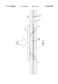
- FIGS. 1A and 1B show sketches of a cross-section and a longitudinal cross-section, respectively, of a preferred embodiment of the method of producing an active optical waveguide having asymmetric polarisation according to the invention, here an active optical fiber;
- FIGS. 2A and 2B show sketches of the cross-section of the active optical fiber in FIG. 1A and its transverse refractive index profile before and after exposure to a transverse illumination of light;
- FIGS. 3A and 3B show sketches of the cross-section of the active optical fiber in FIG. 1A and its transverse photorefractive dopant profile
- FIGS. 4A and 4B show sketches of other transverse index profiles before and after exposure to a transverse illumination of light
- FIG. 5 shows a sketch of a longitudinal cross-section of a preferred embodiment of an active optical fiber simultaneously having a Bragg grating written into the guiding region thereof;
- FIGS. 6A and 6B show sketches of preferred embodiments of a single polarisation mode and a five-wavelength single polarisation mode, respectively, optical fiber laser having a pump light source and a distributed feedback comprising one or more of the active optical fibers with Bragg gratings shown in FIG. 5;
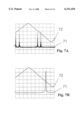
- FIGS. 7A and 7B show measured Fabry-Perot scannings of normalized laser power output versus frequency of an active optical fiber according to prior art and a preferred embodiment of an active optical fiber according to the invention
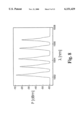
- FIG. 8 shows a measured scanning of power output versus wavelength of a preferred embodiment of the five-wavelength single mode optical fiber laser shown in FIG. 6B;
- FIGS. 9A and 9B show the laser power outputs versus wavelength at the peak wavelength of 1555.6 nm of a preferred single polarisation mode optical fiber laser as shown in FIG. 6A, and of said laser further equipped with a commercial booster, respectively;
- FIG. 10 shows the bit error rate (BER) versus received optical power (ROP) of a preferred single polarisation mode optical fiber laser as shown in FIG. 6A;
- FIG. 11 shows a sketch of a preferred embodiment of an absolute calibrated laser light source
- FIG. 12 shows a graph of transmission through the gas cell versus frequency of the absolute calibrated laser light source shown in FIG. 11 indicating the locking point (LP).
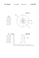
- FIGS. 1A and 1B show sketches of a cross-section and a longitudinal cross-section, respectively, of a preferred embodiment of the method of producing an active optical waveguide having asymmetric polarisation according to the invention.
- An active optical waveguide in a preferred embodiment an active optical fiber based on silica, 10 comprises a 4 ⁇ m diameter guiding region 11 containing an active dopant, in this embodiment erbium, a non-guiding region 12 of 31-37 ⁇ m thickness surrounding the guiding region, and an intermediate region 13 of 1-7 ⁇ m thickness between said guiding and non-guiding regions.
- the active optical fiber has a numerical aperture of about 0.27 and after exposure, in this embodiment UV light from a KrF excimer laser with 248 nm light, exhibits light guiding modes having different polarisations as exemplified by the two orthogonal arrows in FIG. 1A.
- the guiding region further contains photorefractive and index raising dopants Ge and Al.
- the intermediate region is doped with photorefractive dopant Ge.
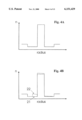
- FIGS. 2A and 2B show the cross-section of the active optical fiber in FIG. 1A and its transverse refractive index profile 21 before exposure, expressed as the refractive index, n versus the radial distance, r, and the modified transverse refractive index profile 22 after exposure of at least a part 10a, 10b of the active optical waveguide to the transverse illumination of light 20, in this embodiment UV light from a KrF excimer laser with 248 nm light.
- the modified transverse refractive index profile has become significantly more elevated in the part of the guiding and intermediate regions proximal to the illuminating light than the part distal thereto; the latter distal parts of the non-modified and modified transverse refractive index profiles being approximately coinciding in this embodiment.
- the resultant asymmetric transverse refractive index profile 22 of this embodiment ensures the polarisation asymmetry of the active optical waveguide.
- the modified transverse refractive index profile is predominantly achieved, in this embodiment, by modifying the transverse refractive index by reacting the transverse illuminating light having a transverse decreasing intensity (due to absorption primarily in the core) through the waveguide 10 with the photorefractive dopant, in this embodiment germanium (Ge) having a transverse photorefractive dopant profile 31 as shown in FIG. 3B.
- the photorefractive dopant in this embodiment germanium (Ge) having a transverse photorefractive dopant profile 31 as shown in FIG. 3B.
- the cross-section of the waveguide is shown in FIG. 3A.
- FIGS. 4A and 4B Other preferred embodiments of the transverse refractive index profile before illumination and the modified transverse refractive index profile after illumination are shown in FIGS. 4A and 4B.
- an active optical fiber based on silica comprises a 4 ⁇ m diameter guiding region.
- the guiding region is doped with about 18 mol-% Ge as photorefractive dopant and about 8 mol-% Al.
- the intermediate region had a thickness of approximately 4.5 ⁇ m and is doped about 1 mol-% Ge and sufficient amount of F to decrease the refractive index to about -2*10 -2 compared to silica.
- the non-guiding region partly doped with P and F has the same index of refraction as the intermediate region and it has the refractive index of silica in the undoped region.
- the active optical fiber has a numerical aperture of about 0.27.
- the erbium concentration in the guiding region is chosen to give an attenuation of about 22 dB/m at 1530 nm.
- This active optical fiber corresponds to the one available under the lot no. 930810 from Lucent Technologies Denmark A/S (former Lycom A/S), Brondby, Denmark.
- the reaction between the illuminating light and the photorefractive dopant is allowed to proceed until the transverse refractive index has become sufficiently modified to selectively suppress the propagation of light in the light guiding modes having different polarisations so that the propagation of light in one mode is less suppressed than the propagation of light in the other mode(s).
- Fabry-Perot interferometer with a free spectral range of 7.5 GHz and a finesse of 75 was used to empirically correlate the exposure and the suppression of light of different polarisations of the exposed active optical fiber, said exposed active optical fiber being equipped with a Bragg grating and mounted in a fiber optical laser set up with distributed feedback.
- FIG. 5 illustrates the method of UV imprinting a grating in a waveguide using the phasemask technique.
- an active optical fiber as described in the invention is illustrated with a guiding region 11, a non-guiding region 12, and an intermediate layer 13.
- the phasemask 51 is 5 cm long and has a 1071 nm spacing and a zero order suppression better than 5%, hence light diffracts predominantly in the 1st and -1st order.
- the diffracted light interferes in the guiding and intermediate regions to produce a grating 52 with a period determined by the grating period of the phasemask 51 and by the effective index of the waveguide.
- FIG. 6A shows a preferred embodiment of a single polarisation mode optical fiber DFB laser 60.
- a 1475 nm/60 mW pump laser 610 is multiplexed with the light at around 1550 nm from the single polarisation mode optical fiber DFB laser using a fiber WDM 613.
- angled connectors 611, 612 are used at both ends of the pump section 61 to reduce internal reflections.
- Fiber pigtailed optical isolators 62, 63 are spliced at both ends of the complete fiber DFB laser module to reduce the effect of external reflections. As illustrated in FIG.
- UV light from a KrF excimer laser operating at 248 nm is used to write the grating 52 in the erbium doped fiber and also to selectively increase the refractive index in the center part of the grating to induce the ⁇ /2 phaseshift necessary for single longitudinal mode operation.
- the surplus pump light propagating in the fiber along with light from the fiber DFB laser may optionally be used to pump another section of erbium doped fiber to act as a booster amplifier 64.
- the ends of the device are fitted with connectors 65, 66 to easily interface to other optical systems.
- FIG. 6B shows a preferred embodiment of a five wavelength single polarisation mode optical fiber DFB laser.
- one single 1480 nm/60 mW pump laser 610 is used to pump five sections of single grating 52 erbium doped fiber.
- the pump light at 1480 nm is multiplexed with the light at around 1550 nm from the single polarisation mode optical fiber DFB lasers using a fiber WDM 613.
- angled connectors 611, 612 are used at both ends of the pump section 61 to reduce internal reflections.
- the sections of single grating 52 erbium doped fiber are spliced 62 to each other to form a linear chain five wavelength single polarisation mode optical fiber DFB laser.
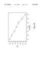
- FIGS. 7A and 7B show frequency scans of the output from an optical fiber DFB laser.
- the laser light was passed through a scanning Fabry-Perot interferometer with a free spectral range of 7.5 GHz and a finesse of 75.
- the scale of the vertical axis is arbitrary while the scale of the abscissa is determined roughly from the extent of the linear ramp voltage 72 which corresponds approximately to the free spectral range of 7.5 GHz.
- the frequency scan 71 of FIG. 7A illustrates the double mode structure of the laser which is obtained if the optical fiber does not have photorefractive dopant in both the guiding region and the intermediate region.
- the frequency scan 71 of FIG. 7B illustrates how a single polarisation mode laser is obtained using an active optical fiber according to the invention. Single polarisation mode operation is secured due to the formation of polarisation asymmetry in the fiber during grating formation according to the invention.
- the output spectrum from the five wavelength single polarisation mode optical fiber DFB laser is illustrated in FIG. 8.
- the spectrum is obtained using an ANDO model AQ-6315A double grating optical spectrum analyzer.
- the peak wavelength separation is 1 nm ⁇ 0.1 nm and the laser power varies between -19 and -11 dBm. This variation is due to the relatively low pump power (60 mW at 1480 nm) and to loss of pump power in non-optimal splices 62 between the individual laser sections, FIG. 6B.
- the signal-to-noise ratio of the laser channels is around 45 dB.
- the output spectrum from the single wavelength single polarisation mode optical fiber DFB laser is illustrated in FIG. 9A and FIG. 9B.
- the spectra are obtained using an ANDO model AQ-6315A double grating optical spectrum analyzer.
- the optical power is -8.2 dBm in the unamplified configuration, FIG. 9A, and +13.4 dBm when amplified with an erbium doped fiber booster amplifier, FIG. 9B.
- the signal-to-noise ratio of the unamplified laser, FIG. 9A is 61 dB, while that of the amplified laser degrades to 44 dB, FIG. 9B.
- the single wavelength single polarisation mode optical fiber DFB laser was tested in a 10 Gbit/s transmission experiment.
- the laser was externally modulated using a Mach-Zender modulator.
- the signal was transmitted over 49.5 km of non-dispersion shifted standard telecommunication fiber with a total loss of 10 dB.
- the measured curve for bit error rate (BER) versus received optical power (ROP) is shown in FIG. 10.
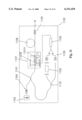
- FIG. 11 shows a preferred embodiment of an absolute wavelength calibrated laser light source 1100 based on a single wavelength single polarisation mode optical fiber DFB laser as described in the invention.
- the laser configuration is basically the same as illustrated in FIG. 6A; a pump laser at 1480 nm 1103 is multiplexed with the DFB laser light using a fiber WDM 1101.
- An isolator 1104 is placed after the pump for stability.
- the surplus pump light propagating in the fiber is used to pump another section of erbium doped fiber to act as a booster amplifier 1108.
- the still remaining pump light is further reflected back into the booster amplifier section 1108 using a UV written pump reflector 1109.
- the active part of the laser with the Bragg grating is fixed on a translation mount 1107 such that it is possible to stretch the fiber. This can be accomplished either by turning a micrometer screw 1107A or by tuning a piezo 1107B. This way the peak wavelength of the single wavelength single polarisation mode optical fiber DFB laser is tuned.
- the absolute value of the laser wavelength is established through controlled absorption in a gas cell 1102 containing a gas with strong absorption lines in the gain band of the laser material. For Er-doped fiber lasers this could be acetylene-13 ( 13 C 2 H 2 ) or krypton (Kr).
- While the laser is operating the peak wavelength of the laser is tuned manually using the micrometer screw thus scanning across the absorption lines of the gas in the gas cell.
- the laser is tuned to a position, the locking point (LP), that coincides with the step part of a strong absorption line.
- the portion of the laser light going in one direction is split using a fiber-optic power divider 1110.
- One part is passed through the gas cell 1102 and directed to a photo diode (PD), the other part is directed directly to another photodiode (PD).
- the signals from the two photo diodes are compared in a differential amplifier 1105. If the laser drifts from its set wavelength position, the output from the differential amplifier changes.
- a servo loop 1106 now provides for the necessary feedback to tune the laser back to its set value by adjusting the voltage that controls the piezo stack; this controls the stretching of the fiber DFB laser and hence the laser wavelength.
- An example of an embodiment of an active optical waveguide having asymmetric polarisation according to the invention was produced in the following way.
- An optical fiber with a transverse refractive index profile and transverse photorefractive dopant profile as shown in FIGS. 4A and 3B, respectively, was provided (lot no. 930810, Lucent Technologies Denmark A/S (former Lycom A/S), Brondby, Denmark). 5 cm of this optical fiber was placed in a groove and illuminated at 248 nm using a KrF excimer laser. The fiber was illuminated with a total fluence of about 1.2 kJ/cm 2 . When illuminated under the same conditions but through a 5 cm long phase mask, Bragg gratings were photoinduced with a peak reflectivity of 99%.
- Polarisation asymmetry was proved by employing such a fiber in a DFB laser configuration, where further the central portion of the illuminated section was illuminated separately to induce a ⁇ /2 phase shift as required for DFB lasers to operate in a single longitudinal mode.
- This laser operated also in a single polarisation mode illustrating the polarisation asymmetry of the waveguide.
- An induced birefringence of 1.5*10 -5 to 3*10 -5 was measured by use of a scanning Fabry-Perot interferometer on a dual-polarisation mode DFB fiber laser; said dual-polarisation mode operation being obtained immediately after single-polarisation mode operation was achieved during the illumination with said KrF excimer laser.
- Bragg gratings were photoinduced using a KrF excimer laser illuminating the fiber with 248 nm light through a 5 cm long phasemask having 1071 nm spacing and zero-order suppression better than 5% (lot no. 6035Y-7-1071-50-3 supplied by QPS, Canada).
- the induced grating was 4.6 cm long and has a peak reflectivity of 99% of 1555.6 nm.
- a phase shift was induced in the central part of the grating by additional UV-exposure.
- the grating was pumped by a semiconductor laser giving 60 mW output around 1475 nm as shown in FIG. 6A.
- the lasing was monitored using an optical spectrum analyzer.
- a scanning Fabry Perot interferometer was used to verify single mode operation. Single mode operation without mode hopping was observed continuously from room temperature up to 200° C. and also at -196° C.
- the laser has a peak wavelength of 1555.6 nm and a signal to noise ratio of 61 dB, measured with a 0.05 nm resolution as shown in FIG. 9A.
- the signal power was 150 ⁇ W with 60 mW pumping.
- a signal power of 22 mW was achieved with a signal to noise ratio of 44 dB as shown in FIG. 9B.
- the laser was put in a block of aluminum which was mounted on an optical table. Further temperature stabilization was not necessary as the wavelength drift due to temperature is as low as 0.01 nm/K.
- the laser was modulated with a 2 31 -1 non-return zero pseudo random bit sequence using a Mach Zehnder modulator controlled by a 10 Gbit/s transmission error test set.
- the signal was transmitted over 49.5 km of standard telecommunication fiber with a total loss of 10 dB.
- the bit error rate curve was measured as shown in FIG. 10 and error free operation was observed during a measurement time of one hour.
- DFB fiber lasers in preferred embodiments according to the present invention are an attractive alternative as sources in telecommunication systems.
- the lasers show excellent long term stability with very high signal to noise ratio and a reasonable output power, combined with exceptional temperature stability and inherent fiber compatibility.
- Each laser 52 was fabricated individually using 5 cm erbium doped fiber (lot no. 930810, supplied by Lucent Technologies Denmark A/S (former Lycom A/S), Br.o slashed.ndby, Denmark) spliced to dispersion shifted fibers and equipped with standard pigtails using angled connectors 62.
- the erbium doped fiber has a core, a cladding and an intermediate region and a dopant concentration of 1.5 ⁇ 10 25 atoms m -3 in the core which has a diameter of 4 ⁇ m and a numerical aperture of 0.27.
- the fiber has a photorefractive dopant profile comprising germanium in the intermediate region.
- the Bragg gratings and polarisation asymmetry are photoinduced simultaneously using a KrF excimer laser with 284 nm light illuminating a 5 cm long phasemask having 1071 nm spacing and zero-order suppression better than 5% (lot no. 6035Y-7-1071-50-3 supplied by QPS, Canada).
- the fluence on the fiber is around 0.4 J/cm 2 per pulse. After around 3000 pulses the 4.2 cm long gratings had a peak reflectivity of 99% corresponding to a grating strength ⁇ L of around three.
- phase shift was then induced in the central part of the grating by additional UV exposure.
- each laser was pumped with a 1480 nm semiconductor laser while the phase shift was induced.
- the lasing was monitored on a spectrum analyzer and a scanning Fabry Perot interferometer with a free spectral range of 7.5 GHz.
- the lasers show high temperature stability. Longitudinal and polarization single mode operation without mode hopping has been verified continuously from room temperature up to 200° C. as well as at -196° C.
- All lasers are written with a single phasemask.
- the wavelength is determined by the applied stress on the fiber during the writing process thereby changing the grating period when releasing the fiber. A wavelength change of about 5 nm can be achieved without breaking the fiber.
- the wavelength reproducibility of our current setup is around 0.2 nm.
- the angled pigtails are cut off and the lasers are spliced together and pumped with the same 60 mW semiconductor laser operating at 1480 nm, thereby forming a multiwavelength source.
- the peak wavelength separation is 1 nm ⁇ 0.1 nm.
- FIG. 8 shows the output from the five lasers. The difference in lasing power is mainly due to relatively low pump power in combination with not fully optimized splicing.
- This example has demonstrated a stable five wavelength optical fiber DFB laser suitable for wavelength division multiplexing (WDM) systems.
- the design principle is easily scaleable to 8 wavelength or more.
- the position of the individual wavelength can be placed more precisely by using a customized phasemask for each desired wavelength.
- the laser wavelength is tuned via stretching of the fiber grating (using a piezo stack 1107B) and absorption of the laser light by a well defined absorption line of a gas in a gas cell 1102 with strong absorption lines within the gain spectrum of the laser.
- erbium doped fiber lasers and acetylene-13, i.e. carbon enriched with carbon-13 were used. While the laser is operating, the laser wavelength may be tuned manually using a micrometer screw 1107C thus scanning across the absorption lines of the gas used.
- the laser is tuned to a frequency position I that coincides with the steep part of the strong P(9) absorption line at 1537.66 nm of acetylene-13.
- the portion of the laser light going in one direction is split using a fiberoptic power divider 1110.
- One part is passed through the gas and directed to a photo diode PD, the other part is directed directly to another photo diode PD.
- the signals from the two photo diodes are sent to the two terminals of a differential amplifier 1105. If the laser drifts from its set wavelength position, the output from the differential amplifier changes.
- a servo loop now provides for the necessary feedback to tune the laser back to its set frequency value and hence maintain the transmission at its set value T (the locking point LP shown in FIG. 12) by adjusting the voltage that controls the piezo stack; this controls the stretching of the fiber DFB laser and hence the laser wavelength.
Abstract
Description
Claims (32)
Priority Applications (1)
| Application Number | Priority Date | Filing Date | Title |
|---|---|---|---|
| US09/364,392 US6151429A (en) | 1997-02-13 | 1999-07-30 | Polarisation asymmetric active optical waveguide, method of its production, and its uses |
Applications Claiming Priority (5)
| Application Number | Priority Date | Filing Date | Title |
|---|---|---|---|
| DK16897 | 1997-02-13 | ||
| DK0168/97 | 1997-02-13 | ||
| US4041597P | 1997-03-13 | 1997-03-13 | |
| PCT/DK1998/000056 WO1998036300A2 (en) | 1997-02-13 | 1998-02-13 | Polarisation asymmetric active optical waveguide, method of its production, and its uses |
| US09/364,392 US6151429A (en) | 1997-02-13 | 1999-07-30 | Polarisation asymmetric active optical waveguide, method of its production, and its uses |
Related Parent Applications (1)
| Application Number | Title | Priority Date | Filing Date |
|---|---|---|---|
| PCT/DK1998/000056 Continuation WO1998036300A2 (en) | 1997-02-13 | 1998-02-13 | Polarisation asymmetric active optical waveguide, method of its production, and its uses |
Publications (1)
| Publication Number | Publication Date |
|---|---|
| US6151429A true US6151429A (en) | 2000-11-21 |
Family
ID=26063442
Family Applications (1)
| Application Number | Title | Priority Date | Filing Date |
|---|---|---|---|
| US09/364,392 Expired - Lifetime US6151429A (en) | 1997-02-13 | 1999-07-30 | Polarisation asymmetric active optical waveguide, method of its production, and its uses |
Country Status (9)
| Country | Link |
|---|---|
| US (1) | US6151429A (en) |
| EP (1) | EP1007999B1 (en) |
| AT (1) | ATE381132T1 (en) |
| AU (1) | AU731781B2 (en) |
| CA (1) | CA2279420C (en) |
| DE (1) | DE69838840T2 (en) |
| DK (1) | DK1007999T3 (en) |
| PT (1) | PT1007999E (en) |
| WO (1) | WO1998036300A2 (en) |
Cited By (37)
| Publication number | Priority date | Publication date | Assignee | Title |
|---|---|---|---|---|
| US6335822B1 (en) * | 1999-03-01 | 2002-01-01 | Nec Corporation | Double cladding fiber and optical fiber amplifier |
| US20020126713A1 (en) * | 2000-10-26 | 2002-09-12 | Mihai Ibanescu | Dielectric waveguide with transverse index variation that support a zero group velocity mode at a non-zero longitudinal wavevector |
| US6459846B1 (en) * | 1999-12-03 | 2002-10-01 | Electronics And Telecommunications Research Institute | Complex rare-earths doped optical waveguide |
| US6487232B1 (en) * | 1998-11-24 | 2002-11-26 | Agilent Technologies, Inc. | System and method for suppressing multimoding behavior of lasers |
| US6490078B2 (en) * | 2000-03-16 | 2002-12-03 | Sumitomo Electric Industries, Ltd. | Optical fiber for optical amplifier, optical fiber amplifier and optical fiber laser |
| US20030219257A1 (en) * | 2002-03-06 | 2003-11-27 | Aston Photonic Technologies Limited | Generating electronic carrier signals in the optical domain |
| US6724528B2 (en) | 2001-02-27 | 2004-04-20 | The United States Of America As Represented By The Secretary Of The Navy | Polarization-maintaining optical fiber amplifier employing externally applied stress-induced birefringence |
| US20040086245A1 (en) * | 2002-03-19 | 2004-05-06 | Farroni Julia A. | Optical fiber |
| US6778747B1 (en) | 1998-09-09 | 2004-08-17 | Corning Incorporated | Radially varying and azimuthally asymmetric optical waveguide fiber |
| US20040258341A1 (en) * | 2003-06-19 | 2004-12-23 | Paolucci Dora M. | Optical waveguide with radiation-tuned birefringence |
| US20040258340A1 (en) * | 2003-06-19 | 2004-12-23 | Paolucci Dora M. | Radiation tuned wavelength filtering device |
| US20040258377A1 (en) * | 2003-06-19 | 2004-12-23 | Berkey George E. | Single polarization optical fiber laser and amplifier |
| US20050094836A1 (en) * | 2003-10-29 | 2005-05-05 | Pedro Manrique | Waveguide modeling and design system |
| DK200301835A (en) * | 2003-12-11 | 2005-06-12 | Koheras As | Single frequency thulium fiber laser |
| US20050180673A1 (en) * | 2004-02-12 | 2005-08-18 | Panorama Flat Ltd. | Faraday structured waveguide |
| US20050180672A1 (en) * | 2004-02-12 | 2005-08-18 | Panorama Flat Ltd. | Apparatus, Method, and Computer Program Product For Multicolor Structured Waveguide |
| US20050180675A1 (en) * | 2004-02-12 | 2005-08-18 | Panorama Flat Limited, A Western Australia Corporation | Apparatus, method, and computer program product for structured waveguide including performance_enhancing bounding region |
| US20050180674A1 (en) * | 2004-02-12 | 2005-08-18 | Panorama Flat Ltd. | Faraday structured waveguide display |
| US20050180723A1 (en) * | 2004-02-12 | 2005-08-18 | Panorama Flat Ltd. | Apparatus, method, and computer program product for structured waveguide including holding bounding region |
| US20050185877A1 (en) * | 2004-02-12 | 2005-08-25 | Panorama Flat Ltd. | Apparatus, Method, and Computer Program Product For Structured Waveguide Switching Matrix |
| US20050201655A1 (en) * | 2004-02-12 | 2005-09-15 | Panorama Flat Ltd. | System, method, and computer program product for structured waveguide including polarizer region |
| US20050201654A1 (en) * | 2004-02-12 | 2005-09-15 | Panorama Flat Ltd. | Apparatus, method, and computer program product for substrated waveguided display system |
| US20050201704A1 (en) * | 2004-02-12 | 2005-09-15 | Panorama Flat Ltd. | Apparatus, method, and computer program product for transverse waveguided display system |
| US20050201679A1 (en) * | 2004-02-12 | 2005-09-15 | Panorama Flat Ltd. | System, method, and computer program product for structured waveguide including modified output regions |
| US20050201651A1 (en) * | 2004-02-12 | 2005-09-15 | Panorama Flat Ltd. | Apparatus, method, and computer program product for integrated influencer element |
| US20050201698A1 (en) * | 2004-02-12 | 2005-09-15 | Panorama Flat Ltd. | System, method, and computer program product for faceplate for structured waveguide system |
| US20050201705A1 (en) * | 2004-02-12 | 2005-09-15 | Panorama Flat Ltd. | Apparatus, method, and computer program product for structured waveguide including recursion zone |
| US20060056792A1 (en) * | 2004-02-12 | 2006-03-16 | Panorama Flat Ltd. | System, method, and computer program product for structured waveguide including intra/inter contacting regions |
| US20060056793A1 (en) * | 2004-02-12 | 2006-03-16 | Panorama Flat Ltd. | System, method, and computer program product for structured waveguide including nonlinear effects |
| US20060056794A1 (en) * | 2004-02-12 | 2006-03-16 | Panorama Flat Ltd. | System, method, and computer program product for componentized displays using structured waveguides |
| US20090190214A1 (en) * | 2008-01-29 | 2009-07-30 | Nicholas Francis Borrelli | Polarizing photorefractive glass |
| US20090190216A1 (en) * | 2008-01-29 | 2009-07-30 | Nicholas Francis Borrelli | Polarizing photorefractive glass |
| US20090238215A1 (en) * | 2004-08-25 | 2009-09-24 | Koheras A/S | Method Of Inducing Refractive Index Structures In A Micro-Structured Fiber, A Micro-Structured Fiber And An Article |
| US20100085632A1 (en) * | 2005-07-08 | 2010-04-08 | Lockheed Martin Corporation | Method and apparatus for pumping and operating optical parametric oscillators using dfb fiber lasers |
| US20160238447A1 (en) * | 2015-02-17 | 2016-08-18 | Samsung Electronics Co., Ltd. | Dual coupler device, spectrometer including the dual coupler device, and non-invasive biometric sensor including the spectrometer |
| US20160341916A1 (en) * | 2014-01-17 | 2016-11-24 | Empire Technology Development Llc | Optical fibers without cladding |
| CN113300195A (en) * | 2020-02-21 | 2021-08-24 | 丰田自动车株式会社 | Amplifying optical fiber and laser emitting device |
Families Citing this family (8)
| Publication number | Priority date | Publication date | Assignee | Title |
|---|---|---|---|---|
| US7280730B2 (en) | 2004-01-16 | 2007-10-09 | Imra America, Inc. | Large core holey fibers |
| JP2008503888A (en) | 2004-06-24 | 2008-02-07 | コヒラス アクティーゼルスカブ | Improvement of parts including optical fiber using fiber Bragg grating and manufacturing method thereof |
| JP4990796B2 (en) | 2004-12-30 | 2012-08-01 | イムラ アメリカ インコーポレイテッド | Photonic bandgap fiber |
| US7787729B2 (en) | 2005-05-20 | 2010-08-31 | Imra America, Inc. | Single mode propagation in fibers and rods with large leakage channels |
| EP1969685A2 (en) | 2005-11-18 | 2008-09-17 | Crystal Fibre A/S | Improved active optical fibers with wavelength-selective filtering mechanism, method of production and their use |
| US7450813B2 (en) | 2006-09-20 | 2008-11-11 | Imra America, Inc. | Rare earth doped and large effective area optical fibers for fiber lasers and amplifiers |
| JP5662151B2 (en) | 2007-09-26 | 2015-01-28 | イムラ アメリカ インコーポレイテッド | Glass large core optical fiber |
| CN102239434B (en) | 2008-12-04 | 2014-11-26 | Imra美国公司 | Highly rare-earth-doped optical fibers for fiber lasers and amplifiers |
Citations (5)
| Publication number | Priority date | Publication date | Assignee | Title |
|---|---|---|---|---|
| US5056888A (en) * | 1989-07-17 | 1991-10-15 | Minnesota Mining And Manufacturing Company | Single-mode, single-polarization optical fiber |
| WO1992010014A1 (en) * | 1990-11-30 | 1992-06-11 | Nkt A/S | A method and apparatus for amplifying an optical signal |
| US5134620A (en) * | 1990-11-20 | 1992-07-28 | General Instrument Corporation | Laser with longitudinal mode selection |
| US5473622A (en) * | 1994-12-29 | 1995-12-05 | At&T Corp. | Cladding-pumped MOPA structure |
| EP0689067A2 (en) * | 1994-06-22 | 1995-12-27 | Fujitsu Limited | Method of producing optical waveguide system, optical device and optical coupler employing the same, optical network and optical circuit board |
-
1998
- 1998-02-13 AT AT98901936T patent/ATE381132T1/en active
- 1998-02-13 EP EP98901936A patent/EP1007999B1/en not_active Expired - Lifetime
- 1998-02-13 DK DK98901936T patent/DK1007999T3/en active
- 1998-02-13 PT PT98901936T patent/PT1007999E/en unknown
- 1998-02-13 AU AU58529/98A patent/AU731781B2/en not_active Expired
- 1998-02-13 CA CA002279420A patent/CA2279420C/en not_active Expired - Lifetime
- 1998-02-13 DE DE69838840T patent/DE69838840T2/en not_active Expired - Lifetime
- 1998-02-13 WO PCT/DK1998/000056 patent/WO1998036300A2/en active IP Right Grant
-
1999
- 1999-07-30 US US09/364,392 patent/US6151429A/en not_active Expired - Lifetime
Patent Citations (5)
| Publication number | Priority date | Publication date | Assignee | Title |
|---|---|---|---|---|
| US5056888A (en) * | 1989-07-17 | 1991-10-15 | Minnesota Mining And Manufacturing Company | Single-mode, single-polarization optical fiber |
| US5134620A (en) * | 1990-11-20 | 1992-07-28 | General Instrument Corporation | Laser with longitudinal mode selection |
| WO1992010014A1 (en) * | 1990-11-30 | 1992-06-11 | Nkt A/S | A method and apparatus for amplifying an optical signal |
| EP0689067A2 (en) * | 1994-06-22 | 1995-12-27 | Fujitsu Limited | Method of producing optical waveguide system, optical device and optical coupler employing the same, optical network and optical circuit board |
| US5473622A (en) * | 1994-12-29 | 1995-12-05 | At&T Corp. | Cladding-pumped MOPA structure |
Non-Patent Citations (2)
| Title |
|---|
| Huang et al. Polarization Rotation in Periodic Loaded Rib Waveguides, Journal of Lightwave Technology, pp1825 1831, Dec. 1992. * |
| Huang et al. Polarization Rotation in Periodic Loaded Rib Waveguides, Journal of Lightwave Technology, pp1825-1831, Dec. 1992. |
Cited By (60)
| Publication number | Priority date | Publication date | Assignee | Title |
|---|---|---|---|---|
| US6778747B1 (en) | 1998-09-09 | 2004-08-17 | Corning Incorporated | Radially varying and azimuthally asymmetric optical waveguide fiber |
| US6487232B1 (en) * | 1998-11-24 | 2002-11-26 | Agilent Technologies, Inc. | System and method for suppressing multimoding behavior of lasers |
| US6335822B1 (en) * | 1999-03-01 | 2002-01-01 | Nec Corporation | Double cladding fiber and optical fiber amplifier |
| US6459846B1 (en) * | 1999-12-03 | 2002-10-01 | Electronics And Telecommunications Research Institute | Complex rare-earths doped optical waveguide |
| US6490078B2 (en) * | 2000-03-16 | 2002-12-03 | Sumitomo Electric Industries, Ltd. | Optical fiber for optical amplifier, optical fiber amplifier and optical fiber laser |
| US20020126713A1 (en) * | 2000-10-26 | 2002-09-12 | Mihai Ibanescu | Dielectric waveguide with transverse index variation that support a zero group velocity mode at a non-zero longitudinal wavevector |
| US6909729B2 (en) * | 2000-10-26 | 2005-06-21 | Massachusetts Institute Of Technology | Dielectric waveguide with transverse index variation that support a zero group velocity mode at a non-zero longitudinal wavevector |
| US6724528B2 (en) | 2001-02-27 | 2004-04-20 | The United States Of America As Represented By The Secretary Of The Navy | Polarization-maintaining optical fiber amplifier employing externally applied stress-induced birefringence |
| US20030219257A1 (en) * | 2002-03-06 | 2003-11-27 | Aston Photonic Technologies Limited | Generating electronic carrier signals in the optical domain |
| US6931031B2 (en) * | 2002-03-06 | 2005-08-16 | Aston University | Generating electronic carrier signals in the optical domain |
| US20040086245A1 (en) * | 2002-03-19 | 2004-05-06 | Farroni Julia A. | Optical fiber |
| US7116887B2 (en) | 2002-03-19 | 2006-10-03 | Nufern | Optical fiber |
| WO2005001530A1 (en) * | 2003-06-19 | 2005-01-06 | 3M Innovative Properties Company | Optical waveguide with radiation-tuned birefringence |
| US20040258341A1 (en) * | 2003-06-19 | 2004-12-23 | Paolucci Dora M. | Optical waveguide with radiation-tuned birefringence |
| US20040258377A1 (en) * | 2003-06-19 | 2004-12-23 | Berkey George E. | Single polarization optical fiber laser and amplifier |
| US20040258340A1 (en) * | 2003-06-19 | 2004-12-23 | Paolucci Dora M. | Radiation tuned wavelength filtering device |
| US7120340B2 (en) * | 2003-06-19 | 2006-10-10 | Corning Incorporated | Single polarization optical fiber laser and amplifier |
| US7197443B2 (en) * | 2003-10-29 | 2007-03-27 | Harman International Industries, Incorporated | Waveguide modeling and design system |
| US20050094836A1 (en) * | 2003-10-29 | 2005-05-05 | Pedro Manrique | Waveguide modeling and design system |
| US7467071B2 (en) | 2003-10-29 | 2008-12-16 | Harman International Industries, Incorporated | Waveguide modeling and design system |
| US20070255539A1 (en) * | 2003-10-29 | 2007-11-01 | Pedro Manrique | Waveguide modeling and design system |
| US7496244B2 (en) | 2003-10-30 | 2009-02-24 | Corning Incorporated | Method for generating a linear single polarization output beam |
| US20090003753A1 (en) * | 2003-10-30 | 2009-01-01 | Berkey George E | Method for generating a linear single polarization output beam |
| WO2005060056A1 (en) * | 2003-12-11 | 2005-06-30 | Koheras A/S | Single frequency thulium waveguide laser and a method of its manufacture |
| US20070153839A1 (en) * | 2003-12-11 | 2007-07-05 | Koheras A/S | Single frequency thulium waveguide laser, an article comprising it, its use and a method of its manufacture |
| DK200301835A (en) * | 2003-12-11 | 2005-06-12 | Koheras As | Single frequency thulium fiber laser |
| US20050201698A1 (en) * | 2004-02-12 | 2005-09-15 | Panorama Flat Ltd. | System, method, and computer program product for faceplate for structured waveguide system |
| US20050180672A1 (en) * | 2004-02-12 | 2005-08-18 | Panorama Flat Ltd. | Apparatus, Method, and Computer Program Product For Multicolor Structured Waveguide |
| US20050201679A1 (en) * | 2004-02-12 | 2005-09-15 | Panorama Flat Ltd. | System, method, and computer program product for structured waveguide including modified output regions |
| US20050201651A1 (en) * | 2004-02-12 | 2005-09-15 | Panorama Flat Ltd. | Apparatus, method, and computer program product for integrated influencer element |
| US20050201654A1 (en) * | 2004-02-12 | 2005-09-15 | Panorama Flat Ltd. | Apparatus, method, and computer program product for substrated waveguided display system |
| US20050201705A1 (en) * | 2004-02-12 | 2005-09-15 | Panorama Flat Ltd. | Apparatus, method, and computer program product for structured waveguide including recursion zone |
| US20060056792A1 (en) * | 2004-02-12 | 2006-03-16 | Panorama Flat Ltd. | System, method, and computer program product for structured waveguide including intra/inter contacting regions |
| US20060056793A1 (en) * | 2004-02-12 | 2006-03-16 | Panorama Flat Ltd. | System, method, and computer program product for structured waveguide including nonlinear effects |
| US20060056794A1 (en) * | 2004-02-12 | 2006-03-16 | Panorama Flat Ltd. | System, method, and computer program product for componentized displays using structured waveguides |
| US20050201655A1 (en) * | 2004-02-12 | 2005-09-15 | Panorama Flat Ltd. | System, method, and computer program product for structured waveguide including polarizer region |
| US20050185877A1 (en) * | 2004-02-12 | 2005-08-25 | Panorama Flat Ltd. | Apparatus, Method, and Computer Program Product For Structured Waveguide Switching Matrix |
| US20050180723A1 (en) * | 2004-02-12 | 2005-08-18 | Panorama Flat Ltd. | Apparatus, method, and computer program product for structured waveguide including holding bounding region |
| US7224854B2 (en) | 2004-02-12 | 2007-05-29 | Panorama Labs Pty. Ltd. | System, method, and computer program product for structured waveguide including polarizer region |
| US20050180676A1 (en) * | 2004-02-12 | 2005-08-18 | Panorama Flat Ltd. | Faraday structured waveguide modulator |
| US7254287B2 (en) | 2004-02-12 | 2007-08-07 | Panorama Labs, Pty Ltd. | Apparatus, method, and computer program product for transverse waveguided display system |
| US20050180674A1 (en) * | 2004-02-12 | 2005-08-18 | Panorama Flat Ltd. | Faraday structured waveguide display |
| US20050180675A1 (en) * | 2004-02-12 | 2005-08-18 | Panorama Flat Limited, A Western Australia Corporation | Apparatus, method, and computer program product for structured waveguide including performance_enhancing bounding region |
| US20050201704A1 (en) * | 2004-02-12 | 2005-09-15 | Panorama Flat Ltd. | Apparatus, method, and computer program product for transverse waveguided display system |
| US20050180673A1 (en) * | 2004-02-12 | 2005-08-18 | Panorama Flat Ltd. | Faraday structured waveguide |
| US7792408B2 (en) | 2004-08-25 | 2010-09-07 | Nkt Photonics A/S | Method of inducing refractive index structures in a micro-structured fiber, a micro-structured fiber and an article |
| US20090238215A1 (en) * | 2004-08-25 | 2009-09-24 | Koheras A/S | Method Of Inducing Refractive Index Structures In A Micro-Structured Fiber, A Micro-Structured Fiber And An Article |
| US8165178B2 (en) * | 2005-07-08 | 2012-04-24 | Lockheed Martin Corporation | Method and apparatus for pumping and operating optical parametric oscillators using DFB fiber lasers |
| US20100085632A1 (en) * | 2005-07-08 | 2010-04-08 | Lockheed Martin Corporation | Method and apparatus for pumping and operating optical parametric oscillators using dfb fiber lasers |
| US8179595B2 (en) * | 2008-01-29 | 2012-05-15 | Corning Incorporated | Polarizing photorefractive glass |
| US20090190216A1 (en) * | 2008-01-29 | 2009-07-30 | Nicholas Francis Borrelli | Polarizing photorefractive glass |
| US20090190214A1 (en) * | 2008-01-29 | 2009-07-30 | Nicholas Francis Borrelli | Polarizing photorefractive glass |
| US20160341916A1 (en) * | 2014-01-17 | 2016-11-24 | Empire Technology Development Llc | Optical fibers without cladding |
| US9946040B2 (en) * | 2014-01-17 | 2018-04-17 | Empire Technology Development Llc | Optical fibers without cladding |
| US20160238447A1 (en) * | 2015-02-17 | 2016-08-18 | Samsung Electronics Co., Ltd. | Dual coupler device, spectrometer including the dual coupler device, and non-invasive biometric sensor including the spectrometer |
| US10466100B2 (en) * | 2015-02-17 | 2019-11-05 | Samsung Electronics Co., Ltd. | Dual coupler device, spectrometer including the dual coupler device, and non-invasive biometric sensor including the spectrometer |
| US10883874B2 (en) | 2015-02-17 | 2021-01-05 | Samsung Electronics Co., Ltd. | Dual coupler device, spectrometer including the dual coupler device, and non-invasive biometric sensor including the spectrometer |
| CN113300195A (en) * | 2020-02-21 | 2021-08-24 | 丰田自动车株式会社 | Amplifying optical fiber and laser emitting device |
| EP3869636A1 (en) * | 2020-02-21 | 2021-08-25 | Toyota Jidosha Kabushiki Kaisha | Amplification fiber and laser beam emitting apparatus |
| US11769980B2 (en) | 2020-02-21 | 2023-09-26 | Toyota Jidosha Kabushiki Kaisha | Amplification fiber and laser beam emitting apparatus |
Also Published As
| Publication number | Publication date |
|---|---|
| CA2279420A1 (en) | 1998-08-20 |
| DE69838840T2 (en) | 2008-12-11 |
| WO1998036300A3 (en) | 1998-11-19 |
| ATE381132T1 (en) | 2007-12-15 |
| DE69838840D1 (en) | 2008-01-24 |
| EP1007999B1 (en) | 2007-12-12 |
| DK1007999T3 (en) | 2008-04-21 |
| WO1998036300A2 (en) | 1998-08-20 |
| AU731781B2 (en) | 2001-04-05 |
| PT1007999E (en) | 2008-01-25 |
| AU5852998A (en) | 1998-09-08 |
| EP1007999A2 (en) | 2000-06-14 |
| CA2279420C (en) | 2007-11-06 |
Similar Documents
| Publication | Publication Date | Title |
|---|---|---|
| US6151429A (en) | Polarisation asymmetric active optical waveguide, method of its production, and its uses | |
| US5881197A (en) | Optical fibre and optical fibre device | |
| US5237576A (en) | Article comprising an optical fiber laser | |
| Othonos | Fiber bragg gratings | |
| EP0829740B1 (en) | Mode coupling optical waveguide grating | |
| US7627006B2 (en) | Multi-wavelength laser source | |
| US5771251A (en) | Optical fibre distributed feedback laser | |
| US5218655A (en) | Article comprising an optical waveguide with in-line refractive index grating | |
| Zhang et al. | Room-temperature power-stabilized narrow-linewidth tunable erbium-doped fiber ring laser based on cascaded Mach-Zehnder interferometers with different free spectral range for strain sensing | |
| Moon et al. | Polarization controlled multi-wavelength Er-doped fiber laser using fiber Bragg grating written in few-mode side-hole fiber with an elliptical core | |
| Hill | Photosensitivity in optical fiber waveguides: from discovery to commercialization | |
| EP1889105A1 (en) | Fiber grating laser | |
| Pureur et al. | Single-polarization fiber lasers using Bragg gratings in Hi-Bi fibers | |
| JP2003510822A (en) | Multi-wavelength laser system | |
| Feng et al. | Switchable and tunable dual-wavelength erbium-doped fiber laser based on one fiber Bragg grating | |
| Othonos et al. | Spectrally broadband Bragg grating mirror for an erbium-doped fiber laser | |
| Douay et al. | Birefringence effect of optical fiber laser with intracore fiber Bragg grating | |
| US8077747B2 (en) | Phosphate glass based optical device and method | |
| Lee et al. | Polarization-sensitive interference spectrum of long-period fiber grating pair separated by erbium-doped fiber | |
| EP1037415A1 (en) | Tunable optical filter | |
| Sakata et al. | Thermooptically Tunable Thulium/Holmium-Codoped Fiber Lasers Based on Multimode Interference Effects | |
| Lee et al. | Fine wavelength tuning of multiwavelength fiber laser with application of strain on cascaded long-period fiber gratings | |
| Mizunami et al. | A narrow-spectrum long-wavelength VCSEL using a fiber Bragg grating | |
| Yang | Multiwavelength linear-Cavity fiber laser source using a Sagnac interferemetric filter and a strain-Induced chirped fiber grating | |
| Sun et al. | Research of fiber gratings, applications in optical communications |
Legal Events
| Date | Code | Title | Description |
|---|---|---|---|
| AS | Assignment |
Owner name: IONAS A/S, DENMARK Free format text: ASSIGNMENT OF ASSIGNORS INTEREST;ASSIGNORS:KRISTENSEN, MARTIN;HUBNER, JORG;VARMING, POUL;AND OTHERS;REEL/FRAME:010512/0305;SIGNING DATES FROM 19991111 TO 19991203 Owner name: LUCENT TECHNOLOGIES DENMARK A/S, DENMARK Free format text: ASSIGNMENT OF ASSIGNORS INTEREST;ASSIGNORS:KRISTENSEN, MARTIN;HUBNER, JORG;VARMING, POUL;AND OTHERS;REEL/FRAME:010512/0305;SIGNING DATES FROM 19991111 TO 19991203 |
|
| STCF | Information on status: patent grant |
Free format text: PATENTED CASE |
|
| AS | Assignment |
Owner name: IONAS A/S, DENMARK Free format text: CHANGE OF ADDRESS;ASSIGNOR:IONAS A/S;REEL/FRAME:013056/0470 Effective date: 20020405 |
|
| AS | Assignment |
Owner name: KOHERAS A/S, DENMARK Free format text: ASSIGNMENT OF ASSIGNORS INTEREST;ASSIGNOR:IONAS A/S;REEL/FRAME:012822/0801 Effective date: 20010701 |
|
| FEPP | Fee payment procedure |
Free format text: PAYER NUMBER DE-ASSIGNED (ORIGINAL EVENT CODE: RMPN); ENTITY STATUS OF PATENT OWNER: LARGE ENTITY Free format text: PAYOR NUMBER ASSIGNED (ORIGINAL EVENT CODE: ASPN); ENTITY STATUS OF PATENT OWNER: LARGE ENTITY |
|
| FEPP | Fee payment procedure |
Free format text: PAYER NUMBER DE-ASSIGNED (ORIGINAL EVENT CODE: RMPN); ENTITY STATUS OF PATENT OWNER: LARGE ENTITY Free format text: PAYOR NUMBER ASSIGNED (ORIGINAL EVENT CODE: ASPN); ENTITY STATUS OF PATENT OWNER: LARGE ENTITY |
|
| FPAY | Fee payment |
Year of fee payment: 4 |
|
| AS | Assignment |
Owner name: OFS FITEL DENMARK I/S, DENMARK Free format text: ASSIGNMENT OF ASSIGNORS INTEREST;ASSIGNOR:LUCENT TECHNOLOGIES DENMARK A/S;REEL/FRAME:019843/0681 Effective date: 20070831 |
|
| FPAY | Fee payment |
Year of fee payment: 8 |
|
| FPAY | Fee payment |
Year of fee payment: 12 |