US6151436A - Splice closure with extended cover - Google Patents
Splice closure with extended cover Download PDFInfo
- Publication number
- US6151436A US6151436A US09/258,188 US25818899A US6151436A US 6151436 A US6151436 A US 6151436A US 25818899 A US25818899 A US 25818899A US 6151436 A US6151436 A US 6151436A
- Authority
- US
- United States
- Prior art keywords
- cover
- closure
- side walls
- radius
- inches
- Prior art date
- Legal status (The legal status is an assumption and is not a legal conclusion. Google has not performed a legal analysis and makes no representation as to the accuracy of the status listed.)
- Expired - Fee Related
Links
Images
Classifications
-
- G—PHYSICS
- G02—OPTICS
- G02B—OPTICAL ELEMENTS, SYSTEMS OR APPARATUS
- G02B6/00—Light guides; Structural details of arrangements comprising light guides and other optical elements, e.g. couplings
- G02B6/44—Mechanical structures for providing tensile strength and external protection for fibres, e.g. optical transmission cables
- G02B6/4439—Auxiliary devices
- G02B6/444—Systems or boxes with surplus lengths
- G02B6/4441—Boxes
- G02B6/4446—Cable boxes, e.g. splicing boxes with two or more multi fibre cables
- G02B6/4447—Cable boxes, e.g. splicing boxes with two or more multi fibre cables with divided shells
Definitions
- This invention relates to optical fiber cable splice closures and, more particularly, to a splice closure having an extended cover for increased closure capacity.
- optical fibers Signal transmission through optical fibers has become, or is becoming, the dominant signal transmission mode.
- the bandwidth characteristics of optical fibers, as well as their relative immunity to certain types of interference and contaminants make optical fibers the desirable transmission medium in high capacity trunk lines as well as in lower capacity feeder and distribution lines.
- individual optical fibers generally are combined in an optical fiber cable which contains a plurality of such fibers, each of which is protected by at least one layer of coating material.
- the fibers are assembled into groups which are held together by binder ribbons or tubes to form a cable core. This is generally enclosed in a metallic or plastic tube or jacket which, in the latter case, often contains one or more strength members, typically of metal, such as heavy gauge wire.
- the fibers are arrayed in ribbon form and the core tube contains one or more stacked ribbons as well as strength members if desired.
- a splice closure which usually comprises a protective case which contains at least one splice tray which, in turn, has a plurality of splice holders mounted thereon, into which the encased individual fiber splices are inserted and held.
- the cables are entrant into the case and generally are clamped to each end thereof to reduce the effects of tensile forces on the cables and on the splices.
- the closure Inasmuch as, at the splice point, the cable itself is opened up and the base fibers are exposed, the only protection afforded the fibers is provided by the closure, which can provide only one or two layers of protection from the outside environment, and the requirements therefor are more stringent than for the cable, which normally provides several layers of protection.
- the closure must anchor the cables stored therein, and it must be capable of withstanding torsional and axial loads transmitted by the cable to the closure so that the splices are protected from these loads.
- the closure must also seal the inner and outer sheaths of the cables and maintain the seal integrity under extreme environmental conditions. In addition, the closure must provide adequate fiber storage for slack fiber without damaging the fibers and without increasing signal attenuation.
- the closure preferably should be capable of storing any type of splice, such as, for example, discrete mechanical, discrete fusion or mass fusion, or other types while reducing forces that tend to damage the splices. Additionally, the closure should provide adequate grounding and anchoring for the metallic strength members of the cable. The closure should also be capable of accepting high fiber count cables as well as those of low fiber count.
- Cables entrant into the enclosure are preferably, and in present day usage, almost always anchored to the splice enclosure itself, to guarantee a minimum of movement of the cable within the enclosure which could unduly stress the fibers and the fiber splices.
- One such anchoring means in the form of a cable grip block, is shown in the aforementioned Burek, et al. U.S. Pat. No. 5,472,160.
- the grip block of that patent is capable of adapting to cables of different sizes, and also provides an anchor for the cable central strength member which is a usual component of loose tube type cables.
- the anchoring arrangement for the cable sheath strength member requires that the strength member or members be cut to a specific length and bent upward into a slot within the grip member.
- the strength members are maintained within the slots against tensile forces because of their rigidity and because they are bent at a right angle. Thus, they function to help maintain the cable against shifting or movement.
- the strength members are preferably of metal and are typically grounded by connection to a ground bolt and lug which passes through a wall of the closure to the outside thereof.
- the lug is connected to earth ground, and is sealed to the outside of the wall of the closure.
- the so-called Ditel Pedestal Plate can be mounted on the dual pedestals of the Burek et al. enclosure, and the splice trays stacked upon a threaded rod extending from the pedestal plate.
- the splice trays can be stacked to the extent that up to 432 discrete fiber splices may be mounted or held.
- an extended cover is unavoidably weakened, or made less resistant to outside forces such as, for example, water pressure in a manhole. It is not uncommon for manholes to contain large amounts of water, even as much as a twenty foot stand of water in a thirty foot deep manhole. When the closure with the extended cover is at the bottom of such a manhole, the twenty foot stand of water can exert enough force on the cover to collapse it, or at least to bend it severely, thereby possibly destroying the water-tight integrity of the closure.
- the splice closure and cover therefor be so constructed as to resist these outside forces so that the interior components of the closure are protected from the deleterious effects of such forces such as, as previously mentioned, the destruction of the water-tight integrity of the closure.
- the present invention is a splice closure of the general type disclosed in the aforementioned Burek et al. Pat. applications, but, through the use of an extended cover, has greatly increased splice storage capacity.
- the cover itself which, like the remainder of the closure shell, is preferably made of a strong, hard, and rigid plastic material, has a plurality of strengthening ribs extending both longitudinally and transversely thereof to produce a cover that is highly resistant to outside forces.
- the pressure of the water can still overcome the strengthened portion of the cover and cause it to warp or collapse, with potential disastrous results.
- the cover of the invention has an additional strengthening configuration in the form of a curved or bowed top (or bottom) surface.
- This curved surface is molded or cast integrally with the transverse strengthening ribs so that it presents an unusually strong and stiff top for the cover, with a portion of the ribs being located inside of the cover and a portion thereof outside of the cover.
- Such a curved surface greatly enhances the resistance of the cover to outside forces, with a consequence that the integrity of the closure is maintained.
- a second embodiment of the invention still more force resistance is added through curved or bowed side walls.
- the side walls and ribs therefor are integrally molded, but the ribs do not extend into the interior of the closure, where they might interfere with the placement or location of other components of the splice closure.
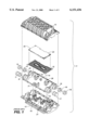
- FIG. 1 is an exploded perspective view of the prior art splice closure disclosed in, for example, the aforementioned Burek et al. applications;
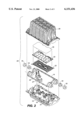
- FIG. 2 is an exploded perspective view of a similar splice closure as modified for increased splice capacity
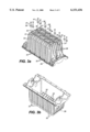
- FIG. 3a is a perspective view of the extended cover of the invention.
- FIG. 3b is a different perspective view of the extended cover of the invention showing a portion of the interior thereof;
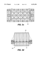
- FIG. 3c is a plan view of the cover of FIGS. 3a and 3b;
- FIG. 3d is a side elevation view of the closure of the invention, with the base member and the cover in place;
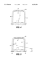
- FIG. 4 is a cross-sectional view of the cover of FIGS. 3a through 3d.
- FIG. 5 is a cross-sectional view of another embodiment of the cover of FIGS. 3a through 3d .
- FIG. 1 there is shown an exploded view of a splice closure 11 as shown in the aforementioned Burek et al. applications and also as shown in U.S. Pat. No. 5,862,290 of Burek et al Closure 11 comprises a base member 12 of suitable material such as hard, rigid, high strength plastic and a cover member 13. Members 12 and 13 are virtually identical and can be produced in the same molds.
- a racetrack grommet 14 provides a cover to base seal as shown, grommet 14 has four cable entrance and exit ports 16, and appropriate inserts 17 and 18 therefor.
- Within base member 12 and resting on the floor thereof are first and second support pedestals 19 and 21 which are adapted to support a pedestal plate member 22.
- Pedestal plate member 22 in turn supports one or more fiber organizers or splice trays 23 and cover 25, which are adapted to be stacked on member 22, each tray 23 being pivotally mounted to the tray immediately below it (not shown).
- Closure 11 also contains grip block members 24 and 26 and a central strength member grip 27.
- the cover 13 fits over the components and mates with base member 12, being sealed thereto by racetrack grommet 14.
- FIG. 2 there is shown a preferred embodiment of the invention which comprises a splice closure 28 having an extended cover 29 which permits stacking a sufficient member of trays 23 to accommodate 648 splices, or enough mass splice trays, which is the subject matter of U.S. patent. application Ser. No. 08/851,102 now U.S. Pat. No. 5,896,486 of Burek et al., to accommodate 2016 splices.
- the extended cover 29 makes possible a considerable increase in the number of splices that can be safely contained within closure 28.
- simple extended cover member 29 is not sufficient to guarantee the resistance of the closure 28, and, more particularly, the cover 29, to outside forces applied to closure 28.
- cover member 29 must be designed and construed to withstand these forces.
- FIGS. 3a to 3c there is shown the extended cover member 29, and in FIG. 3d, the assembled splice closure 28, comprising base member 12 and extended cover 29.
- cover 29 as molded has a plurality of longitudinal strengthening ribs 31, and a plurality of transverse strengthening ribs 32, which strengthen both the side walls 33 and the top (as viewed in FIG. 3a) surface 34, being vertically oriented on the center surface of the side walls.
- diagonal ribs 36 are positioned on the top surface 34.
- the end walls 37 also are strengthened by vertical ribs 38.
- the ribs 31, 32, and 36 are preferably integral with their respective surfaces.
- a plurality of nuts 39 and bolts 41 are shown as indicative of any of a number of possible means for joining cover 29 to base 12.
- the term "top" corresponds to the orientation as shown in the figures, and not necessarily to the orientation of the closure in use.
- top surface 34 is curved or bowed with a radius A, which preferably is within the range of 28 to 32 inches, with 30 inches being preferred.
- radius A which preferably is within the range of 28 to 32 inches, with 30 inches being preferred.
- top surface 34 is not located along the bottom edge of the ribs 32, but, over a portion of its width, is located approximately mid-way between the top and bottom edges of ribs 32.
- surface or top wall 34 is molded integrally with the ribs 32, the combination of the top 34 and ribs 32, wherein ribs 32 support or strengthen top 34 below as well as above it, the structure is considerably stronger and more resistant to outside forces incident upon the closure, such as shock, water pressure, and the like.
- FIG. 5 there is shown a second embodiment of the invention wherein the side walls 33 are also bowed outwardly with a radius D of, for example, 42 to 46 inches.
- the ribs 32 are not bowed but have a varying width and do not extend or intrude into the interior of the closure in order that there be no interference with the internal components or structure of the closure.
- the side walls 33 have straight interior surfaces 43 which are canted or sloped at approximately a two degree (20) angle from bottom to top.
- the outer surfaces 44 of side walls 33 are bowed, as shown, the locus of their radius D being a distance C above the plane of the flanges 46 of the cover 29.
- the distance C is preferably in the range of two and one-half inches (21/2") to three inches (3") , with approximately two and three-quarter inches being preferred.
- the curvature of the outer surfaces 44 begins at approximately three and one half inches (31/2") from the plane of the flanges 46. This is not an absolutely necessary configuration, but it does serve to facilitate removal of cover 29 from the mold.
- the extended cover of the invention allows the stacking of numerous splice holders or trays within the closure, without any sacrifice of structural strength.
- the cover of the invention is sufficiently resistant to outside forces that the closure integrity is maintained despite these forces, and the physical location of the splice closure is not dependent upon avoidance of such forces.
Abstract
Description
Claims (12)
Priority Applications (1)
| Application Number | Priority Date | Filing Date | Title |
|---|---|---|---|
| US09/258,188 US6151436A (en) | 1999-02-25 | 1999-02-25 | Splice closure with extended cover |
Applications Claiming Priority (1)
| Application Number | Priority Date | Filing Date | Title |
|---|---|---|---|
| US09/258,188 US6151436A (en) | 1999-02-25 | 1999-02-25 | Splice closure with extended cover |
Publications (1)
| Publication Number | Publication Date |
|---|---|
| US6151436A true US6151436A (en) | 2000-11-21 |
Family
ID=22979481
Family Applications (1)
| Application Number | Title | Priority Date | Filing Date |
|---|---|---|---|
| US09/258,188 Expired - Fee Related US6151436A (en) | 1999-02-25 | 1999-02-25 | Splice closure with extended cover |
Country Status (1)
| Country | Link |
|---|---|
| US (1) | US6151436A (en) |
Cited By (21)
| Publication number | Priority date | Publication date | Assignee | Title |
|---|---|---|---|---|
| US7822310B2 (en) * | 2007-02-28 | 2010-10-26 | Corning Cable Systems Llc | Fiber optic splice trays |
| US20120106913A1 (en) * | 2010-10-28 | 2012-05-03 | Elli Makrides-Saravanos | Impact resistant fiber optic enclosures and related methods |
| US20130014974A1 (en) * | 2011-07-14 | 2013-01-17 | Burke Edward J | Sealing mechanism and method for drop cable splice enclosures |
| US8467651B2 (en) | 2009-09-30 | 2013-06-18 | Ccs Technology Inc. | Fiber optic terminals configured to dispose a fiber optic connection panel(s) within an optical fiber perimeter and related methods |
| US8520996B2 (en) | 2009-03-31 | 2013-08-27 | Corning Cable Systems Llc | Removably mountable fiber optic terminal |
| WO2014094291A1 (en) * | 2012-12-21 | 2014-06-26 | 3M Innovative Properties Company | Device and method for protecting optical fiber splice closure |
| US8792767B2 (en) | 2010-04-16 | 2014-07-29 | Ccs Technology, Inc. | Distribution device |
| US8798427B2 (en) | 2007-09-05 | 2014-08-05 | Corning Cable Systems Llc | Fiber optic terminal assembly |
| US8873926B2 (en) | 2012-04-26 | 2014-10-28 | Corning Cable Systems Llc | Fiber optic enclosures employing clamping assemblies for strain relief of cables, and related assemblies and methods |
| US8879882B2 (en) | 2008-10-27 | 2014-11-04 | Corning Cable Systems Llc | Variably configurable and modular local convergence point |
| US8909019B2 (en) | 2012-10-11 | 2014-12-09 | Ccs Technology, Inc. | System comprising a plurality of distribution devices and distribution device |
| US9004778B2 (en) | 2012-06-29 | 2015-04-14 | Corning Cable Systems Llc | Indexable optical fiber connectors and optical fiber connector arrays |
| US9049500B2 (en) | 2012-08-31 | 2015-06-02 | Corning Cable Systems Llc | Fiber optic terminals, systems, and methods for network service management |
| EP2820459A4 (en) * | 2012-02-29 | 2015-10-14 | 3M Innovative Properties Co | Optical fiber cable splicing box |
| US9219546B2 (en) | 2011-12-12 | 2015-12-22 | Corning Optical Communications LLC | Extremely high frequency (EHF) distributed antenna systems, and related components and methods |
| US9323020B2 (en) | 2008-10-09 | 2016-04-26 | Corning Cable Systems (Shanghai) Co. Ltd | Fiber optic terminal having adapter panel supporting both input and output fibers from an optical splitter |
| US9547144B2 (en) | 2010-03-16 | 2017-01-17 | Corning Optical Communications LLC | Fiber optic distribution network for multiple dwelling units |
| US9547145B2 (en) | 2010-10-19 | 2017-01-17 | Corning Optical Communications LLC | Local convergence point for multiple dwelling unit fiber optic distribution network |
| US10110307B2 (en) | 2012-03-02 | 2018-10-23 | Corning Optical Communications LLC | Optical network units (ONUs) for high bandwidth connectivity, and related components and methods |
| US10222569B1 (en) * | 2017-09-06 | 2019-03-05 | Facebook, Inc. | Cable management enclosure |
| US10656358B2 (en) * | 2017-07-25 | 2020-05-19 | Ofs Fitel, Llc | Fiber optic network distribution module for use along an outdoor multi-fiber network distribution cable |
Citations (2)
| Publication number | Priority date | Publication date | Assignee | Title |
|---|---|---|---|---|
| US5472160A (en) * | 1994-06-22 | 1995-12-05 | At&T Corp. | Splice closure and grip block |
| US5862290A (en) * | 1997-05-01 | 1999-01-19 | Lucent Technologies Inc. | Optical fiber cable splice closure |
-
1999
- 1999-02-25 US US09/258,188 patent/US6151436A/en not_active Expired - Fee Related
Patent Citations (2)
| Publication number | Priority date | Publication date | Assignee | Title |
|---|---|---|---|---|
| US5472160A (en) * | 1994-06-22 | 1995-12-05 | At&T Corp. | Splice closure and grip block |
| US5862290A (en) * | 1997-05-01 | 1999-01-19 | Lucent Technologies Inc. | Optical fiber cable splice closure |
Cited By (29)
| Publication number | Priority date | Publication date | Assignee | Title |
|---|---|---|---|---|
| US7822310B2 (en) * | 2007-02-28 | 2010-10-26 | Corning Cable Systems Llc | Fiber optic splice trays |
| US8798427B2 (en) | 2007-09-05 | 2014-08-05 | Corning Cable Systems Llc | Fiber optic terminal assembly |
| US9323020B2 (en) | 2008-10-09 | 2016-04-26 | Corning Cable Systems (Shanghai) Co. Ltd | Fiber optic terminal having adapter panel supporting both input and output fibers from an optical splitter |
| US8879882B2 (en) | 2008-10-27 | 2014-11-04 | Corning Cable Systems Llc | Variably configurable and modular local convergence point |
| US8520996B2 (en) | 2009-03-31 | 2013-08-27 | Corning Cable Systems Llc | Removably mountable fiber optic terminal |
| US8467651B2 (en) | 2009-09-30 | 2013-06-18 | Ccs Technology Inc. | Fiber optic terminals configured to dispose a fiber optic connection panel(s) within an optical fiber perimeter and related methods |
| US9547144B2 (en) | 2010-03-16 | 2017-01-17 | Corning Optical Communications LLC | Fiber optic distribution network for multiple dwelling units |
| US8792767B2 (en) | 2010-04-16 | 2014-07-29 | Ccs Technology, Inc. | Distribution device |
| US9720197B2 (en) | 2010-10-19 | 2017-08-01 | Corning Optical Communications LLC | Transition box for multiple dwelling unit fiber optic distribution network |
| US9547145B2 (en) | 2010-10-19 | 2017-01-17 | Corning Optical Communications LLC | Local convergence point for multiple dwelling unit fiber optic distribution network |
| US8755663B2 (en) * | 2010-10-28 | 2014-06-17 | Corning Cable Systems Llc | Impact resistant fiber optic enclosures and related methods |
| US20120106913A1 (en) * | 2010-10-28 | 2012-05-03 | Elli Makrides-Saravanos | Impact resistant fiber optic enclosures and related methods |
| US8686289B2 (en) * | 2011-07-14 | 2014-04-01 | Channell Commercial Corporation | Sealing mechanism and method for drop cable splice enclosures |
| US20130014974A1 (en) * | 2011-07-14 | 2013-01-17 | Burke Edward J | Sealing mechanism and method for drop cable splice enclosures |
| US10110305B2 (en) | 2011-12-12 | 2018-10-23 | Corning Optical Communications LLC | Extremely high frequency (EHF) distributed antenna systems, and related components and methods |
| US9602209B2 (en) | 2011-12-12 | 2017-03-21 | Corning Optical Communications LLC | Extremely high frequency (EHF) distributed antenna systems, and related components and methods |
| US9800339B2 (en) | 2011-12-12 | 2017-10-24 | Corning Optical Communications LLC | Extremely high frequency (EHF) distributed antenna systems, and related components and methods |
| US9219546B2 (en) | 2011-12-12 | 2015-12-22 | Corning Optical Communications LLC | Extremely high frequency (EHF) distributed antenna systems, and related components and methods |
| EP2820459A4 (en) * | 2012-02-29 | 2015-10-14 | 3M Innovative Properties Co | Optical fiber cable splicing box |
| US9513450B2 (en) | 2012-02-29 | 2016-12-06 | 3M Innovative Properties Company | Optical fiber cable splicing box |
| US10110307B2 (en) | 2012-03-02 | 2018-10-23 | Corning Optical Communications LLC | Optical network units (ONUs) for high bandwidth connectivity, and related components and methods |
| US8873926B2 (en) | 2012-04-26 | 2014-10-28 | Corning Cable Systems Llc | Fiber optic enclosures employing clamping assemblies for strain relief of cables, and related assemblies and methods |
| US9004778B2 (en) | 2012-06-29 | 2015-04-14 | Corning Cable Systems Llc | Indexable optical fiber connectors and optical fiber connector arrays |
| US9049500B2 (en) | 2012-08-31 | 2015-06-02 | Corning Cable Systems Llc | Fiber optic terminals, systems, and methods for network service management |
| US8909019B2 (en) | 2012-10-11 | 2014-12-09 | Ccs Technology, Inc. | System comprising a plurality of distribution devices and distribution device |
| WO2014094291A1 (en) * | 2012-12-21 | 2014-06-26 | 3M Innovative Properties Company | Device and method for protecting optical fiber splice closure |
| US10656358B2 (en) * | 2017-07-25 | 2020-05-19 | Ofs Fitel, Llc | Fiber optic network distribution module for use along an outdoor multi-fiber network distribution cable |
| US10222569B1 (en) * | 2017-09-06 | 2019-03-05 | Facebook, Inc. | Cable management enclosure |
| US20190072735A1 (en) * | 2017-09-06 | 2019-03-07 | Facebook, Inc. | Cable management enclosure |
Similar Documents
| Publication | Publication Date | Title |
|---|---|---|
| US6151436A (en) | Splice closure with extended cover | |
| US6192180B1 (en) | Tray for splicing optical ribbon fibers | |
| RU2164357C2 (en) | Device for distributing optical fiber joints | |
| US5995700A (en) | Mass fusion splice tray | |
| US6591053B2 (en) | Fiber optic wall mount cabinet | |
| AU697480B2 (en) | Closure with cable strain relief | |
| AU709556B2 (en) | Dome shaped closure for fibre optics | |
| US7333706B2 (en) | Enclosure and organizer for telecommunication lines and splices | |
| US6229948B1 (en) | Apparatus for pole-mounting an optical fiber splice closure | |
| US5907653A (en) | Racetrack grommet for optical fiber cable splice closure | |
| US6249633B1 (en) | Fiber optic splice closure including side pivoting slack storage holder and associated methods | |
| JPH0682664A (en) | Optical fiber cable | |
| EP1129380A1 (en) | Fiber optic splice closure including end pivoting slack storage holder and associated methods | |
| JPH05508482A (en) | cable | |
| US5838871A (en) | Device for organizing optical fiber cable connections and optical cable joint box | |
| CA2403507C (en) | System for storing splices in a joint box | |
| US6173101B1 (en) | Fiber optic cable | |
| JP3245244B2 (en) | Optical fiber holding structure | |
| KR20060059288A (en) | Slot type optical cable with high compression resistance | |
| EP1176446B1 (en) | Optic fibre separator | |
| JPH09152515A (en) | Optical connection part storage tray | |
| JPS60138505A (en) | Optical cable connection box | |
| MXPA97007080A (en) | Envelope with release of ac effort | |
| WO2003016973A2 (en) | Optical fibre management devices | |
| JPH08278416A (en) | Extra length housing part of optical fiber and its storage method |
Legal Events
| Date | Code | Title | Description |
|---|---|---|---|
| AS | Assignment |
Owner name: LUCENT TECHNOLOGIES INC., NEW JERSEY Free format text: ASSIGNMENT OF ASSIGNORS INTEREST;ASSIGNORS:BUREK, DENIS EDWARD;JONES, MARC DUANE;MALLUCK, JOHN FRANCIS;REEL/FRAME:009797/0322 Effective date: 19900224 |
|
| AS | Assignment |
Owner name: AVAYA TECHNOLOGY CORP., NEW JERSEY Free format text: ASSIGNMENT OF ASSIGNORS INTEREST;ASSIGNOR:LUCENT TECHNOLOGIES INC.;REEL/FRAME:012691/0572 Effective date: 20000929 |
|
| AS | Assignment |
Owner name: BANK OF NEW YORK, THE, NEW YORK Free format text: SECURITY AGREEMENT;ASSIGNOR:AVAYA TECHNOLOGY CORP.;REEL/FRAME:012775/0144 Effective date: 20020405 |
|
| REMI | Maintenance fee reminder mailed | ||
| LAPS | Lapse for failure to pay maintenance fees | ||
| STCH | Information on status: patent discontinuation |
Free format text: PATENT EXPIRED DUE TO NONPAYMENT OF MAINTENANCE FEES UNDER 37 CFR 1.362 |
|
| FP | Lapsed due to failure to pay maintenance fee |
Effective date: 20041121 |
|
| AS | Assignment |
Owner name: AVAYA TECHNOLOGY CORPORATION, NEW JERSEY Free format text: RELEASE BY SECURED PARTY;ASSIGNOR:THE BANK OF NEW YORK;REEL/FRAME:019881/0532 Effective date: 20040101 |
|
| AS | Assignment |
Owner name: COMMSCOPE SOLUTIONS PROPERTIES, LLC, NEVADA Free format text: ASSIGNMENT OF ASSIGNORS INTEREST;ASSIGNOR:AVAYA TECHNOLOGY CORPORATION;REEL/FRAME:019974/0906 Effective date: 20040129 |
|
| AS | Assignment |
Owner name: COMMSCOPE, INC. OF NORTH CAROLINA, NORTH CAROLINA Free format text: MERGER;ASSIGNOR:COMMSCOPE SOLUTIONS PROPERTIES, LLC;REEL/FRAME:019991/0643 Effective date: 20061220 Owner name: COMMSCOPE, INC. OF NORTH CAROLINA,NORTH CAROLINA Free format text: MERGER;ASSIGNOR:COMMSCOPE SOLUTIONS PROPERTIES, LLC;REEL/FRAME:019991/0643 Effective date: 20061220 |
|
| AS | Assignment |
Owner name: BANK OF AMERICA, N.A., AS ADMINISTRATIVE AGENT, CA Free format text: SECURITY AGREEMENT;ASSIGNORS:COMMSCOPE, INC. OF NORTH CAROLINA;ALLEN TELECOM, LLC;ANDREW CORPORATION;REEL/FRAME:020362/0241 Effective date: 20071227 Owner name: BANK OF AMERICA, N.A., AS ADMINISTRATIVE AGENT,CAL Free format text: SECURITY AGREEMENT;ASSIGNORS:COMMSCOPE, INC. OF NORTH CAROLINA;ALLEN TELECOM, LLC;ANDREW CORPORATION;REEL/FRAME:020362/0241 Effective date: 20071227 |
|
| AS | Assignment |
Owner name: ANDREW LLC (F/K/A ANDREW CORPORATION), NORTH CAROL Free format text: PATENT RELEASE;ASSIGNOR:BANK OF AMERICA, N.A., AS ADMINISTRATIVE AGENT;REEL/FRAME:026039/0005 Effective date: 20110114 Owner name: ALLEN TELECOM LLC, NORTH CAROLINA Free format text: PATENT RELEASE;ASSIGNOR:BANK OF AMERICA, N.A., AS ADMINISTRATIVE AGENT;REEL/FRAME:026039/0005 Effective date: 20110114 Owner name: COMMSCOPE, INC. OF NORTH CAROLINA, NORTH CAROLINA Free format text: PATENT RELEASE;ASSIGNOR:BANK OF AMERICA, N.A., AS ADMINISTRATIVE AGENT;REEL/FRAME:026039/0005 Effective date: 20110114 |
|
| AS | Assignment |
Owner name: AVAYA INC. (FORMERLY KNOWN AS AVAYA TECHNOLOGY COR Free format text: BANKRUPTCY COURT ORDER RELEASING ALL LIENS INCLUDING THE SECURITY INTEREST RECORDED AT REEL/FRAME 012775/0144;ASSIGNOR:THE BANK OF NEW YORK;REEL/FRAME:044893/0179 Effective date: 20171128 |