US6151448A - Electric heater for a livestock water tank - Google Patents
Electric heater for a livestock water tank Download PDFInfo
- Publication number
- US6151448A US6151448A US09/239,837 US23983799A US6151448A US 6151448 A US6151448 A US 6151448A US 23983799 A US23983799 A US 23983799A US 6151448 A US6151448 A US 6151448A
- Authority
- US
- United States
- Prior art keywords
- connector
- heating element
- electric
- male
- plug
- Prior art date
- Legal status (The legal status is an assumption and is not a legal conclusion. Google has not performed a legal analysis and makes no representation as to the accuracy of the status listed.)
- Expired - Lifetime
Links
Images


Classifications
-
- A—HUMAN NECESSITIES
- A01—AGRICULTURE; FORESTRY; ANIMAL HUSBANDRY; HUNTING; TRAPPING; FISHING
- A01K—ANIMAL HUSBANDRY; CARE OF BIRDS, FISHES, INSECTS; FISHING; REARING OR BREEDING ANIMALS, NOT OTHERWISE PROVIDED FOR; NEW BREEDS OF ANIMALS
- A01K7/00—Watering equipment for stock or game
- A01K7/02—Automatic devices ; Medication dispensers
- A01K7/027—Drinking equipment with water heaters, coolers or means for preventing freezing
-
- F—MECHANICAL ENGINEERING; LIGHTING; HEATING; WEAPONS; BLASTING
- F24—HEATING; RANGES; VENTILATING
- F24H—FLUID HEATERS, e.g. WATER OR AIR HEATERS, HAVING HEAT-GENERATING MEANS, e.g. HEAT PUMPS, IN GENERAL
- F24H9/00—Details
- F24H9/18—Arrangement or mounting of grates or heating means
- F24H9/1809—Arrangement or mounting of grates or heating means for water heaters
- F24H9/1818—Arrangement or mounting of electric heating means
-
- H—ELECTRICITY
- H05—ELECTRIC TECHNIQUES NOT OTHERWISE PROVIDED FOR
- H05B—ELECTRIC HEATING; ELECTRIC LIGHT SOURCES NOT OTHERWISE PROVIDED FOR; CIRCUIT ARRANGEMENTS FOR ELECTRIC LIGHT SOURCES, IN GENERAL
- H05B3/00—Ohmic-resistance heating
- H05B3/02—Details
- H05B3/06—Heater elements structurally combined with coupling elements or holders
-
- H—ELECTRICITY
- H05—ELECTRIC TECHNIQUES NOT OTHERWISE PROVIDED FOR
- H05B—ELECTRIC HEATING; ELECTRIC LIGHT SOURCES NOT OTHERWISE PROVIDED FOR; CIRCUIT ARRANGEMENTS FOR ELECTRIC LIGHT SOURCES, IN GENERAL
- H05B3/00—Ohmic-resistance heating
- H05B3/78—Heating arrangements specially adapted for immersion heating
- H05B3/82—Fixedly-mounted immersion heaters
Definitions
- This invention relates generally to electric water heaters, and more particularly to electric water heaters for use in livestock water tanks exposed to low temperature extremes.
- Livestock require large amounts of water throughout the year.
- exterior livestock watering tanks are seasonally equipped with electric water heaters to prevent the water contained therein from icing over during cold temperatures. These heaters either float in the tank or rest on the bottom of the tank.
- the power cord extends from the heater and over the side wall of the tank for connection to a power outlet. Because the heater is not fixed in the tank in these prior designs, it is possible for the heater to be thrown from the tank when an animal drags on the power cord.
- water tanks typically include a drain opening in their side wall so that the tanks can be drained, e.g. for transporting or for putting in fresh water. It is desirable to have a tank heater in which the power cord extends from the tank through the drain opening so that cord is out of reach of the livestock.
- the size of the drain plug opening varies depending on the manufacturer, and in many instances the drain openings are too small to permit the male plug of the power cord to be inserted through the opening.
- a tank heater that can be mounted through a variety of sizes of drain plug openings without modifying the drain plug or the water heater.
- An object of the present invention is to provide an electric heater for use in livestock watering tanks that reduces the likelihood of the heater being displaced from the tank.
- Another object of the present invention is to provide an electric heater that can be used with a variety of different commercially available water tanks, wherein the power cord for the heater extends through the drain plug opening of the tank.
- Still another object of the present invention is to provide an electric water tank heater that is low cost and economical to manufacture.
- a further object of the present invention is to provide an electric water tank heater that is rugged and durable.
- Still another object of the present invention is to provide an electric water tank heater that can be installed through drain plug openings of varying diameters.
- an electric water heater that includes an electric heating element adapted to be positioned within a water tank.
- a male electric plug has a housing supporting a power prong and a neutral prong for insertion into a conventional electrical outlet.
- a power cord extends between the heating element and the male plug and is adapted to deliver power from the male plug to the heating element.
- the power cord includes a detachable connector interposed between the heating element and the male plug such that the power cord can be separated for insertion through the drain plug opening.
- the detachable connector can be positioned anywhere along the length of the power cord, and may have a portion that is integrally formed with the male plug or the housing of the heater.
- the heater includes a temperature control device interconnected between the power cord and the heating element for regulating power to the heating element to maintain the temperature of the contents of the tank within a preselected range.
- the interconnection between the heating element, the temperature control device and the power cord is contained within a hermetically sealed housing.
- the housing includes a threaded boss that surrounds the proximal end of the power cord and is sized for insertion through the drain plug opening. A nut threads onto the boss from outside the tank to secure the heater to the tank. A seal is compressed between the housing and the tank to seal the drain opening around the boss.
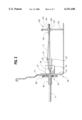
- FIG. 1 is a perspective view of an electric heater for a livestock water tank according to the present invention
- FIG. 2 is cross sectional view along line 2--2 of FIG. 1;
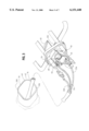
- FIG. 3 is a perspective view illustrating the interconnection between the power cord, the heating element and the temperature control device
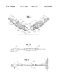
- FIG. 4 is a perspective view of a detachable cord connector employed in the electric heater of FIG. 1;
- FIG. 5 is a partial elevation view of the power cord of the electric heater of FIG. 1 showing the detachable cord connector at a location adjacent the male plug of the power cord;
- FIG. 6 is a partial side view of the power cord of the electric heater showing an alternative location for the detachable cord connector
- FIG. 7 is a partial side view of the power cord of the electric heater showing an embodiment wherein a portion of the detachable connector is integrally formed with the male plug;
- FIG. 8 is a partial side view of the electric heater showing an embodiment in which a portion of the detachable connector is integrally formed with the housing of the heater;
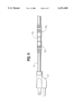
- FIG. 9 is a partial side view of the power cord of the electric heater showing a reduced diameter detachable connector
- FIGS. 10 and 11 are elevation views of the front and back faces of a nut employed in the present invention.
- FIG. 12 is a partial side view of an alternative embodiment of the heater in which the housing has a cone-shaped back face.
- an improved electric water tank heater 10 includes an electric heating element 12 that is mountable within a water tank 14 for heating the contents of the tank.
- a power cord 16 is interconnected with the heating element 12 through a temperature control device 18 for delivering electrical power to the heating element in a controlled fashion so as to regulate the temperature of the contents of the tank 14.
- the power cord 16 extends through the drain plug opening 20 (see FIG. 2 and 8) of the tank 14 and terminates in a conventional male plug 22 that is configured for insertion into a conventional power outlet (not shown).
- the heater 10 includes a housing 26 that hermetically seals the interconnection temperature control device 18, the power cord 16, and the heating element 12 from moisture infiltration.
- the housing 26 includes a mechanism for affixing the heater to the drain plug opening 20 in a sealed manner, thereby preventing inadvertent removal of the heater 10 and also preventing the contents of the tank 14 from leaking out of the drain plug opening 20.
- the power cord 16 includes an outer insulating sheath 30 enclosing a line or "hot" conducting wire 32a, a neutral conducting wire 32b, and a ground conducting wire 32c.
- Each wire 32a-c is further provided with its own insulating sheath.
- the distal end 35 of the power cord 16 is connected to conventional three-prong electrical plug 22.
- Three prongs 34a-c extend from the front face of the plug 22 and are oriented for insertion into a convention power outlet.
- the plug includes a line prong 34a, a neutral prong 34b, and a ground prong 34c.
- the power cord 16 extends from the rear of the plug 22 with the sheath 30 of the power cord being encapsulated within the body of the plug. Within the plug, the sheath 30 has been removed to allow the wires 32a-c to be separated for interconnection with the appropriate conductive prongs 34a-c.
- the line wire 32a is electrically and mechanically interconnected with the line prong 34a
- the neutral wire 32b is electrically and mechanically interconnected with the neutral prong 34b
- the ground wire 32c is electrically and mechanically interconnected with the ground prong 34c.
- the proximal end 36 of the power cord 16 extends into the housing 26 where it is electrically interconnected with the heating element 12 and the temperature control device 18.
- the housing 26 includes an outer shell 40 that defines an inner cavity 42 enclosing the interconnection between the power cord 16, the temperature control device 18, and the heating element 12.
- the outer shell 40 is formed from a suitable material such as plastic in a conventional manner such as injection molding.
- the inner cavity 42 is hermetically sealed by filling it with a suitable waterproof sealant such as epoxy resin or a silicone sealing material.
- the heating element 12 is in the form of an elongated tubular member.
- the first and second ends 50, 66 of the heating element 12 are positioned within the housing 26 where they are appropriately interconnected with the power cord.
- the first end 50 of the heating element 12 is connected to the proximal end of the line wire 32a through the temperature control device 18 and the second end 60 of the heating element 12 is connected to the neutral conductor wire 32b.
- the ground conductor wire 32c is connected to a bracket 54 which is used to secure the temperature control 18 device to a thermally conductive strap 56.
- the temperature control device 18 is in the form of a thermostat or temperature responsive switch that is interposed between the heating element 12 and the power cord 16.
- the temperature control device 18 is disposed in the cavity 42 and has a first terminal 46 and a second terminal 48.
- the first terminal 46 is connected to the proximal end of the line wire 32a and the second terminal 48 is connected to the first end 50 of the elongated heating element by a wire 52.
- the temperature control device 18 senses the temperature of the contents of the tank 14 through a thermally conductive strap 56 and cycles the heating element 12 on and off to maintain the contents of the tank within a predetermined temperature range.
- the thermally conductive strap 56 is affixed at its midpoint in a thermally conductive manner to the temperature control device 18.
- the point of attachment divides the strap 56 into a heat sensing segment 58 and a cooling segment 60.
- the heat sensing segment 56 extends from the housing 26 and is affixed at its distal end 62 to the elongated heating element 12.
- the cooling segment 60 of the thermally conductive strap 56 similarly projects from the housing 26, but avoids contact with the heating element 12. Insulating tape surrounds the temperature control device 18 to prevent minimize the heat sink of the epoxy filler on the temperature control device 18.
- the heating element 12 includes a first linear portion 70 that extends from the housing 26 in a direction generally perpendicular to the drain plug opening 20.
- the first linear portion 70 extends to a curved portion 72 that in turn extends into a second linear portion 74.
- the second linear portion 74 is spaced apart from and generally parallel to first linear portion 70.
- the second linear portion 74 extends back towards the housing 26 and into a third linear portion 76 that extends generally perpendicular from the second linear portion 74.
- the third linear portion 76 extends into a fourth linear portion 78 that is generally perpendicular to the third linear portion 76.
- the fourth linear portion 78 extends away from the housing 26 and into a curved portion 80 that in turn extends into a fifth linear portion 82.
- the fifth linear portion 82 is generally parallel to and spaced apart from the fourth linear portion 78.
- the fifth linear portion 82 extends back into the housing 26 where it is interconnected with the power cord 16 as described above.
- the shape of the heating element 12 is merely illustrative and that the heating element may take numerous other configurations without departing from the scope of the present invention.
- a suitable alternative is illustrated in aforementioned U.S. Pat. No. 4,835,366.
- a drain plug connector 84 is provided for mounting the heater 10 through the drain plug opening 20 of the water tank 14.
- the drain plug connector 84 includes a threaded boss 86 extending from the back of the housing 26.
- the threaded boss 86 surrounds the proximal end 36 of the power cord 16 and is sized for insertion through the drain plug opening 20.
- a reciprocal nut 88 threads onto the boss 86 from outside the tank 14 to secure the housing 26 to the tank.
- the nut 88 includes a slot 90 (see FIGS. 9 and 10) to allow it to slide into place over the power cord 16.
- the nut 88 is then threaded onto the boss 86 and tightened against the tank 14.
- a rubber washer 92 fits around the boss and, as is shown in FIG.
- the washer 92 may be positioned on the outside of the tank, as is shown in FIG. 2. The washer 92 forms a watertight seal at the drain plug opening 20 to prevent leakage therethrough.
- the tank heater 10 is configured for use in water tanks having drain plug openings ranging from 0.75 inches in diameter to 2.0 inches in diameter.
- the threaded boss 86 preferably has an outer diameter that is less than 0.75 inches.
- the seal washer 92 preferably has an inner diameter which approximates the outer diameter of the boss 86 and an outer diameter that is greater than 2.0 inches.
- the back wall 94 of the housing 26 is also configured to extend beyond the edge of a 2 inch diameter drain plug opening.
- the housing 26 has a planar back wall 94 that is on the order of 2.75 inches wide and 3.25 inches high.
- the nut has an outer diameter on the order of 2.75 to 3.0 inches.
- the housing 26 has been illustrated with a planar back wall, it will be appreciated that other housing configurations are also suitable.
- the housing 26 can have a cone-shaped back face 300 that will fit into drain plug openings of varying diameters.
- a cone-shaped gasket 302 fits over the cone-shaped back wall to seal the drain opening.
- the gasket 302 can be a separate component from the housing or it can be in the form of a layer of gasket material bonded to the outside of the housing.
- the nut may include annular ribs 109, 110 that are sized to fit within drain plug openings of different diameters.
- a first face of the nut 88 has an annular rib 109 having a first diameter
- a second face of the nut 88 has an annular rib 110 having a reduced diameter compared to the rib on the first face.
- Each face of the nut 88 also has an outer rib 111 which is configured to abut against the side wall of the water tank 14 when the nut 88 is tightened onto the boss 86.
- the inner annular ribs 109, 110 project beyond the outer ribs 111 such that the inwardly facing of the inner annular ribs 109, 110 will extend into the drain plug opening 20 when the nut 88 is tightened onto the boss 86.
- the first annular rib 109 preferably has a diameter of approximately 2.0 inches
- the second annular rib 110 preferably has a diameter of approximately 1.5 inches.
- the interface between the inner annular rib 109, 110 and the drain plug opening 20 functions to support the heater in the tank.
- the back wall 94 of the housing 26 may rest on the bottom of the water tank 14 to further support the heating element 12 within the tank. (See FIG. 2).
- Each support post 100 includes a downwardly extending leg 102 connected to a clamp member 104 in a height adjustable manner.
- the support leg 102 rests on the bottom wall of the tank 14 and the clamp member 104 in turn engages with the heating element 12 to support it against vertical displacement relative to bottom wall of the tank.
- the support leg 102 is in the form of a conventional bolt
- the clamp member 104 is in the form of a pair of dish shaped members 106a, b that are configured to clamp about the heating element 12 at one of its curved portions 72, 80.
- Nuts 107 thread onto bolt on both sides of the members. The nuts 107 are used to adjust the heights of the members 106, 108 relative to the floor and to clamp the members 106, 108 to the heating element 12.
- the nuts 107 may be integrally formed with the members 106, 108.
- the power cord 16 includes detachable connector 120 interposed between the housing 26 and the male plug 22.
- the connector 120 allows the power cord 16 to be separated into a first section 124 that extends between a first portion 126 of the detachable connector 120 and the housing 26, and a second section 128 that extends between a second portion 130 of the detachable connector 120 and the male plug 22.
- the connector first portion is in the form of a male connector that carries three conductive pins 132a-c.
- the conductive pins 132a-c extend from the end of the connector first portion 126 and are oriented for insertion into reciprocal terminal openings 134a-c in the (female) connector second portion 130.
- the connector first portion 126 carries a line connector pin 132a, a neutral connector pin 132b, and a ground connector pin 132c.
- the line pin 132a is connected with the line wire 32a from the power cord first portion 124
- the neutral pin 132b is connected with the neutral wire 32b from the power cord first portion 124
- the ground pin 132c is connected to the ground wire 132c from the power cord first portion 124.
- the connector second portion 130 includes a line terminal opening 134a, a neutral terminal opening 134b, and a ground terminal opening 134c.
- Electrical contacts 136a-c are positioned within the openings 134a-c and are electrically interconnected with the appropriate wires 32a-c from the power cord second portion 128.
- a line contact terminal 136a is interconnected with the line wire 32a from the power cord second portion 128,
- a neutral contact terminal 136b is interconnected with the neutral conductor 32b from the power cord second portion 128, and
- a ground contact terminal 136c is interconnected with ground wire 32c from the power cord second portion 128.
- the connector first portion 126 includes an annular flange 138 or shroud that extends around the connector pins 132.
- the flange 138 is configured to slide over the reduced diameter annular end portion 140 of the connector second portion 130.
- a longitudinal rib 142 formed on the inner wall of the flange 138 is configured to slide into a reciprocal slot 144 formed on the annular end portion 140 of the connector second portion 130. The interface between the rib 142 and the slot 144 fixes the orientation of the connector first portion 126 relative to the connector second portion 130, thereby ensuring that the pins 132a-c are inserted into the proper terminals openings 134a-c.
- the detachable connector 120 has round cross-sectional configuration and a tubular overall appearance.
- the connector 120 could have numerous other cross-sectional shapes, such as square, rectangular or triangular, without departing from the scope of the invention.
- the detachable connector 120 can be located anywhere along the length of the power cord 16. For example, in the embodiment illustrated in FIGS. 1 and 5, the detachable connector is located proximal to the plug 22, whereas in FIG. 6 the detachable connector is shown at a location proximal to the heating element 12.
- FIG. 7 illustrates an embodiment in which the detachable connector second portion 130 is integrally formed with the male plug 22.
- the prongs 34a-c of the plug 22 may be integrally formed with the contact terminals 136a-c of the connector second portion 130, or the prongs 34a-c and contact terminals 136a-c may be interconnected by wires.
- FIG. 8 illustrates an embodiment in which the detachable connector first portion 126 is integrally formed with the threaded boss 86.
- the inner ends of the pins 132a-c are preferably connected to wires that extend through the boss 86 and into the inner cavity 42 where they are interconnected with the heating element 12 and the temperature control device 18.
- the detachable connector 120 has a maximum outer cross sectional dimension 144 that is smaller than the maximum outer cross-section dimension 146 of the plug 22.
- the cord 16 can be separated into two pieces so the cord can be passed through openings that are too small to permit passage of the plug 22.
- the detachable connector 120 preferably has a maximum outer cross-sectional dimension 144 that is less than 0.75 inches.
- the outer cross-sectional dimension 144 of the connector 120 is larger than that of the diameter power cord 16.
- the size of connector 120 could be reduced so that its outer cross-sectional dimension approximates that of the power cord 16, as is shown in FIG. 9.
- the housing has a two-part construction consisting of a main portion 200 and an end cap 202.
- the main portion 200 consists of the threaded boss 86, the back wall 94 and the cavity defining outer wall 40.
- the end cap 202 is configured to be inserted into the open end 206 of the wall 40.
- the first and second ends 50, 66 of the heating element 12 extend through the end cap 202 into the inner cavity 42 of the housing 26.
- the heating and cooling segments 58, 60 of the conductive strap 54 extend out through end cap 202. In this manner, the end cup 202 fixes the orientation of the segments 58, 60 relative to each other and relative to the heating element 12.
- the drain plug (not shown) is removed from the water tank 14 and the heater 10 is positioned on the floor of the tank.
- the power cord 16 is separated into two sections 124, 128 and the connector first portion 126 is fed out through the drain plug opening 20.
- the washer 92 is then slid over the power cord first portion 124 from its distal end and into position over the boss 86.
- the threaded boss 86 is then pushed through the drain plug opening 20 and the back wall 94 of the housing 26 is aligned against the inside of the tank wall.
- the nut 92 is then slid into place on the power cord first portion 124 and threaded onto the boss 86.
- the washer 92 is compressed between the tank 14 and the housing 26 to form a watertight seal at the opening 20.
- the connector first and second portions are then reconnected to each other by inserting the pins 132a-c into the openings 134a-c.
Abstract
Description
Claims (21)
Priority Applications (3)
| Application Number | Priority Date | Filing Date | Title |
|---|---|---|---|
| US09/239,837 US6151448A (en) | 1999-01-29 | 1999-01-29 | Electric heater for a livestock water tank |
| CA002291988A CA2291988C (en) | 1999-01-29 | 1999-12-07 | Electric heater for a livestock water tank |
| US09/638,563 US6353708B1 (en) | 1999-01-29 | 2000-08-14 | Apparatus for mounting an electrical heater through a water tank drain plug opening |
Applications Claiming Priority (1)
| Application Number | Priority Date | Filing Date | Title |
|---|---|---|---|
| US09/239,837 US6151448A (en) | 1999-01-29 | 1999-01-29 | Electric heater for a livestock water tank |
Related Child Applications (1)
| Application Number | Title | Priority Date | Filing Date |
|---|---|---|---|
| US09/638,563 Continuation-In-Part US6353708B1 (en) | 1999-01-29 | 2000-08-14 | Apparatus for mounting an electrical heater through a water tank drain plug opening |
Publications (1)
| Publication Number | Publication Date |
|---|---|
| US6151448A true US6151448A (en) | 2000-11-21 |
Family
ID=22903944
Family Applications (1)
| Application Number | Title | Priority Date | Filing Date |
|---|---|---|---|
| US09/239,837 Expired - Lifetime US6151448A (en) | 1999-01-29 | 1999-01-29 | Electric heater for a livestock water tank |
Country Status (2)
| Country | Link |
|---|---|
| US (1) | US6151448A (en) |
| CA (1) | CA2291988C (en) |
Cited By (14)
| Publication number | Priority date | Publication date | Assignee | Title |
|---|---|---|---|---|
| US6317559B1 (en) * | 1999-09-15 | 2001-11-13 | Du Nyun Kim | Apparatus for sealing the end portion of a hot-water tube in which electric heating wires are inserted |
| US6484666B1 (en) | 2001-11-21 | 2002-11-26 | Allied Precision Industries Inc. | Bird bath |
| US20030013331A1 (en) * | 2001-07-12 | 2003-01-16 | Reusche Thomas K. | Reduced dimension male electric plug |
| US6640747B2 (en) | 2001-11-21 | 2003-11-04 | Allied Precision Industries, Inc. | Bird bath |
| US6707988B2 (en) | 2001-06-13 | 2004-03-16 | Allied Precision Industries, Inc. | Universal drain plug heater for livestock water tanks |
| US6810206B1 (en) * | 2001-09-21 | 2004-10-26 | Farm Innovators, Inc. | Drain plug heater |
| US6836615B1 (en) * | 2003-07-15 | 2004-12-28 | Ken A. Bradenbaugh | Heat dissipation device and water heater including the same |
| US20060029375A1 (en) * | 2004-08-05 | 2006-02-09 | Bradenbaugh Ken A | Water heater and method of mounting a heating element in a water heater |
| US20060199128A1 (en) * | 2005-02-15 | 2006-09-07 | Spx Corporation | Panel mount electrical connector in a burner enclosure apparatus and method |
| US20070034622A1 (en) * | 2005-08-09 | 2007-02-15 | Daniel Ruminski | Heating device and use thereof |
| US20090314787A1 (en) * | 2008-06-19 | 2009-12-24 | Reusche Thomas K | Deicer anchoring system |
| CN104052103A (en) * | 2013-03-15 | 2014-09-17 | 李尔公司 | Replaceable adapter for use with vehicular battery charging system |
| USD826485S1 (en) | 2017-09-29 | 2018-08-21 | Miller Manufacturing Company | Livestock water trough heater |
| US11291184B2 (en) | 2019-04-16 | 2022-04-05 | Kelly Nienke | Watering tank circulating assembly |
Families Citing this family (1)
| Publication number | Priority date | Publication date | Assignee | Title |
|---|---|---|---|---|
| CN108120028A (en) * | 2018-01-31 | 2018-06-05 | 大庆永胜石油设备有限责任公司 | Dual-use with gasoline and electricity environmental protection and energy saving Water-cooled boiler |
Citations (14)
| Publication number | Priority date | Publication date | Assignee | Title |
|---|---|---|---|---|
| US3641473A (en) * | 1970-05-28 | 1972-02-08 | Thomas J Attaway | Vehicle-grounding clamp |
| US3746836A (en) * | 1971-12-15 | 1973-07-17 | Mattel Inc | Aquarium heater |
| US4068116A (en) * | 1975-12-09 | 1978-01-10 | Nelson Manufacturing Company | Thermostatically protected electric immersion water heater |
| US4124793A (en) * | 1978-01-13 | 1978-11-07 | Metaframe Corporation | Aquarium water heater |
| US4848616A (en) * | 1987-02-05 | 1989-07-18 | Rheem Manufacturing Company | Electric immersion heating unit with readily removable and replaceable galvanic current control resistor |
| US4946396A (en) * | 1988-10-19 | 1990-08-07 | Takara Co., Ltd. | Adapter for connector to external power supply |
| US5109474A (en) * | 1991-02-26 | 1992-04-28 | Robertshaw Controls Company | Immersion heating element with conductive polymeric fitting |
| US5159659A (en) * | 1991-02-26 | 1992-10-27 | Robertshaw Controls Company | Hot water tank construction, electrically operated heating element construction therefor and methods of making the same |
| US5191634A (en) * | 1991-01-11 | 1993-03-02 | Wellman Thermal Systems Corporation | Screw plug immersion heater comprising separate header and threaded sleeve sections |
| US5395264A (en) * | 1993-02-05 | 1995-03-07 | Keith; Carlton L. | Electrical connector/adapter |
| US5462452A (en) * | 1993-11-22 | 1995-10-31 | Devine; Michael J. | Breakaway extension cord for preventing electrical plug damage |
| US5828810A (en) * | 1996-04-26 | 1998-10-27 | Nine Lives, Inc. | Positive temperature coefficient bar shaped immersion heater |
| US5990455A (en) * | 1998-04-23 | 1999-11-23 | Chesterfield Products, Inc. | Chafing dish |
| US6028294A (en) * | 1997-05-15 | 2000-02-22 | Kim Hotstart Manufacturing Company | Heater assembly |
-
1999
- 1999-01-29 US US09/239,837 patent/US6151448A/en not_active Expired - Lifetime
- 1999-12-07 CA CA002291988A patent/CA2291988C/en not_active Expired - Lifetime
Patent Citations (15)
| Publication number | Priority date | Publication date | Assignee | Title |
|---|---|---|---|---|
| US3641473A (en) * | 1970-05-28 | 1972-02-08 | Thomas J Attaway | Vehicle-grounding clamp |
| US3746836A (en) * | 1971-12-15 | 1973-07-17 | Mattel Inc | Aquarium heater |
| US4068116A (en) * | 1975-12-09 | 1978-01-10 | Nelson Manufacturing Company | Thermostatically protected electric immersion water heater |
| US4124793A (en) * | 1978-01-13 | 1978-11-07 | Metaframe Corporation | Aquarium water heater |
| US4848616A (en) * | 1987-02-05 | 1989-07-18 | Rheem Manufacturing Company | Electric immersion heating unit with readily removable and replaceable galvanic current control resistor |
| US4946396A (en) * | 1988-10-19 | 1990-08-07 | Takara Co., Ltd. | Adapter for connector to external power supply |
| US5191634A (en) * | 1991-01-11 | 1993-03-02 | Wellman Thermal Systems Corporation | Screw plug immersion heater comprising separate header and threaded sleeve sections |
| US5109474A (en) * | 1991-02-26 | 1992-04-28 | Robertshaw Controls Company | Immersion heating element with conductive polymeric fitting |
| US5159659A (en) * | 1991-02-26 | 1992-10-27 | Robertshaw Controls Company | Hot water tank construction, electrically operated heating element construction therefor and methods of making the same |
| US5305419A (en) * | 1991-02-26 | 1994-04-19 | Robertshaw Controls Company | Hot water tank construction, electrically operated heating element construction therefor and methods of making the same |
| US5395264A (en) * | 1993-02-05 | 1995-03-07 | Keith; Carlton L. | Electrical connector/adapter |
| US5462452A (en) * | 1993-11-22 | 1995-10-31 | Devine; Michael J. | Breakaway extension cord for preventing electrical plug damage |
| US5828810A (en) * | 1996-04-26 | 1998-10-27 | Nine Lives, Inc. | Positive temperature coefficient bar shaped immersion heater |
| US6028294A (en) * | 1997-05-15 | 2000-02-22 | Kim Hotstart Manufacturing Company | Heater assembly |
| US5990455A (en) * | 1998-04-23 | 1999-11-23 | Chesterfield Products, Inc. | Chafing dish |
Cited By (21)
| Publication number | Priority date | Publication date | Assignee | Title |
|---|---|---|---|---|
| US6317559B1 (en) * | 1999-09-15 | 2001-11-13 | Du Nyun Kim | Apparatus for sealing the end portion of a hot-water tube in which electric heating wires are inserted |
| US6707988B2 (en) | 2001-06-13 | 2004-03-16 | Allied Precision Industries, Inc. | Universal drain plug heater for livestock water tanks |
| US20030013331A1 (en) * | 2001-07-12 | 2003-01-16 | Reusche Thomas K. | Reduced dimension male electric plug |
| US6810206B1 (en) * | 2001-09-21 | 2004-10-26 | Farm Innovators, Inc. | Drain plug heater |
| US6484666B1 (en) | 2001-11-21 | 2002-11-26 | Allied Precision Industries Inc. | Bird bath |
| US6640747B2 (en) | 2001-11-21 | 2003-11-04 | Allied Precision Industries, Inc. | Bird bath |
| US6836615B1 (en) * | 2003-07-15 | 2004-12-28 | Ken A. Bradenbaugh | Heat dissipation device and water heater including the same |
| US20050013597A1 (en) * | 2003-07-15 | 2005-01-20 | Bradenbaugh Ken A. | Heat dissipation device and water heater including the same |
| WO2006017818A3 (en) * | 2004-08-05 | 2006-10-26 | Kenneth A Bradenbaugh | Water heater and method of mounting a heating element in a water heater |
| US20060029375A1 (en) * | 2004-08-05 | 2006-02-09 | Bradenbaugh Ken A | Water heater and method of mounting a heating element in a water heater |
| WO2006017818A2 (en) * | 2004-08-05 | 2006-02-16 | Bradenbaugh Kenneth A | Water heater and method of mounting a heating element in a water heater |
| US20060199128A1 (en) * | 2005-02-15 | 2006-09-07 | Spx Corporation | Panel mount electrical connector in a burner enclosure apparatus and method |
| US7497728B2 (en) * | 2005-02-15 | 2009-03-03 | Spx Corporation | Panel mount electrical connector in a burner enclosure apparatus and method |
| US20070034622A1 (en) * | 2005-08-09 | 2007-02-15 | Daniel Ruminski | Heating device and use thereof |
| US20090314787A1 (en) * | 2008-06-19 | 2009-12-24 | Reusche Thomas K | Deicer anchoring system |
| US8121466B2 (en) * | 2008-06-19 | 2012-02-21 | Allied Precision Industries, Inc. | Deicer anchoring system |
| CN104052103A (en) * | 2013-03-15 | 2014-09-17 | 李尔公司 | Replaceable adapter for use with vehicular battery charging system |
| US20140273645A1 (en) * | 2013-03-15 | 2014-09-18 | Lear Corporation | Replaceable Adapter For Use With Vehicular Battery Charging System |
| US9876317B2 (en) * | 2013-03-15 | 2018-01-23 | Lear Corporation | Replaceable adapter for use with vehicular battery charging system |
| USD826485S1 (en) | 2017-09-29 | 2018-08-21 | Miller Manufacturing Company | Livestock water trough heater |
| US11291184B2 (en) | 2019-04-16 | 2022-04-05 | Kelly Nienke | Watering tank circulating assembly |
Also Published As
| Publication number | Publication date |
|---|---|
| CA2291988A1 (en) | 2000-07-29 |
| CA2291988C (en) | 2007-06-05 |
Similar Documents
| Publication | Publication Date | Title |
|---|---|---|
| US6151448A (en) | Electric heater for a livestock water tank | |
| US4068116A (en) | Thermostatically protected electric immersion water heater | |
| FI85412C (en) | FOERBINDNINGSSTYCKE FOER UPPHETTNINGSBARA SLANGAR. | |
| US4640226A (en) | Bird watering apparatus | |
| US3916149A (en) | Electric heater element connection assembly | |
| US6353708B1 (en) | Apparatus for mounting an electrical heater through a water tank drain plug opening | |
| US6157777A (en) | Heater assembly for a fluid conduit with an integral heater | |
| CA2323222C (en) | Apparatus for mounting an electrical heater through a water tank drain plug opening | |
| US6707988B2 (en) | Universal drain plug heater for livestock water tanks | |
| US4091261A (en) | Electrically heated animal watering device | |
| US6810206B1 (en) | Drain plug heater | |
| CN210779193U (en) | Plug device | |
| ES1299367U (en) | Electric vehicle charging plug with seals (Machine-translation by Google Translate, not legally binding) | |
| ES2239950T3 (en) | ELECTRICALLY HEATED HOSE FOR WINDSHIELD CLEANER INSTALLATION. | |
| EP0594296A1 (en) | Water heater electric control dam with wire entry | |
| KR200490758Y1 (en) | Rainproof type protecting cover of concent | |
| US4025755A (en) | Thermostatic electric cable heater | |
| KR102594937B1 (en) | Heat wire temperature controller for freeze protection equipped with a waterproof structure | |
| BR202023004486U2 (en) | ELECTRIC VEHICLE CHARGING PLUG WITH SEALS | |
| JPH1062268A (en) | Hot water heater for ornamental fish | |
| US3096425A (en) | Floating electric heater for stock watering tank | |
| JPS6338926B2 (en) | ||
| GB1592243A (en) | Plug for a motor vehicle ignition system | |
| GB2110918A (en) | Boot heaters | |
| CN212006265U (en) | Dry burning prevention sensor |
Legal Events
| Date | Code | Title | Description |
|---|---|---|---|
| AS | Assignment |
Owner name: ALLIED PRECISION INDUSTRIES INC., ILLINOIS Free format text: ASSIGNMENT OF ASSIGNORS INTEREST;ASSIGNORS:OWEN, DONALD B.;REUSCHE, THOMAS K.;REEL/FRAME:009982/0914 Effective date: 19990513 |
|
| STCF | Information on status: patent grant |
Free format text: PATENTED CASE |
|
| FEPP | Fee payment procedure |
Free format text: PAYOR NUMBER ASSIGNED (ORIGINAL EVENT CODE: ASPN); ENTITY STATUS OF PATENT OWNER: LARGE ENTITY |
|
| FPAY | Fee payment |
Year of fee payment: 4 |
|
| FPAY | Fee payment |
Year of fee payment: 8 |
|
| AS | Assignment |
Owner name: AMERICAN CHARTERED BANK, ILLINOIS Free format text: LIEN;ASSIGNOR:ALLIED PRECISION INDUSTRIES, INC.;REEL/FRAME:024202/0794 Effective date: 20020701 Owner name: AMERICAN CHARTERED BANK,ILLINOIS Free format text: LIEN;ASSIGNOR:ALLIED PRECISION INDUSTRIES, INC.;REEL/FRAME:024202/0794 Effective date: 20020701 |
|
| FPAY | Fee payment |
Year of fee payment: 12 |
|
| FEPP | Fee payment procedure |
Free format text: PAT HOLDER NO LONGER CLAIMS SMALL ENTITY STATUS, ENTITY STATUS SET TO UNDISCOUNTED (ORIGINAL EVENT CODE: STOL); ENTITY STATUS OF PATENT OWNER: LARGE ENTITY |
|
| FEPP | Fee payment procedure |
Free format text: PAYER NUMBER DE-ASSIGNED (ORIGINAL EVENT CODE: RMPN); ENTITY STATUS OF PATENT OWNER: LARGE ENTITY Free format text: PAYOR NUMBER ASSIGNED (ORIGINAL EVENT CODE: ASPN); ENTITY STATUS OF PATENT OWNER: LARGE ENTITY |
|
| AS | Assignment |
Owner name: MILLER MANUFACTURING COMPANY, MINNESOTA Free format text: ASSIGNMENT OF ASSIGNORS INTEREST;ASSIGNOR:ALLIED PRECISION INDUSTRIES, INC.;REEL/FRAME:032152/0921 Effective date: 20140102 |