US6151536A - Dispensing system and methods - Google Patents
Dispensing system and methods Download PDFInfo
- Publication number
- US6151536A US6151536A US09/162,251 US16225198A US6151536A US 6151536 A US6151536 A US 6151536A US 16225198 A US16225198 A US 16225198A US 6151536 A US6151536 A US 6151536A
- Authority
- US
- United States
- Prior art keywords
- processor
- item
- items
- auxiliary storage
- lock
- Prior art date
- Legal status (The legal status is an assumption and is not a legal conclusion. Google has not performed a legal analysis and makes no representation as to the accuracy of the status listed.)
- Expired - Lifetime
Links
- 238000000034 method Methods 0.000 title claims abstract description 35
- 230000000007 visual effect Effects 0.000 claims description 12
- 238000004891 communication Methods 0.000 claims description 5
- 238000012546 transfer Methods 0.000 description 7
- 239000003814 drug Substances 0.000 description 3
- 238000013459 approach Methods 0.000 description 2
- 230000008878 coupling Effects 0.000 description 2
- 238000010168 coupling process Methods 0.000 description 2
- 238000005859 coupling reaction Methods 0.000 description 2
- 239000006260 foam Substances 0.000 description 2
- 238000012986 modification Methods 0.000 description 2
- 230000004048 modification Effects 0.000 description 2
- 238000004806 packaging method and process Methods 0.000 description 2
- 238000010276 construction Methods 0.000 description 1
- 238000012423 maintenance Methods 0.000 description 1
- 230000000737 periodic effect Effects 0.000 description 1
- 238000000926 separation method Methods 0.000 description 1
Images


Classifications
-
- G—PHYSICS
- G07—CHECKING-DEVICES
- G07F—COIN-FREED OR LIKE APPARATUS
- G07F17/00—Coin-freed apparatus for hiring articles; Coin-freed facilities or services
- G07F17/0092—Coin-freed apparatus for hiring articles; Coin-freed facilities or services for assembling and dispensing of pharmaceutical articles
Definitions
- the invention relates generally to the field of dispensing systems, and in particular to dispensing systems for the controlled dispensing of medical supply items, including pharmaceutical items. More particularly, the invention provides for the dispensing of items from an auxiliary storage location based on information input into a medical supply dispensing cabinet.
- Such dispensing units may include the use of item buttons which are disposed near where the items are stored within the dispensing unit.
- the item buttons are touched to record the removal or addition of items to or from the dispensing unit.
- the use of such item buttons has proved to be tremendously successful in the health care industry.
- a dispensing cabinet having a processor with an entry device to enter user identification information and charge account information, such as a patient's identification number, into the processor.
- An auxiliary storage location is separate from the dispensing cabinet and has at least one door and a lock to lock the door. The lock is operated on receipt of a signal from the processor after the appropriate information has been entered into the processor.
- the dispensing cabinet further includes at least one item sensor which is in communication with the processor. The item sensor is actuated to record removal of an item from the auxiliary storage location.
- Such a system is preferably operated by entering into the processor both user identification information and charge account information to cause the processor to send a signal to unlock the lock.
- the user actuates one of the item sensors on the dispensing cabinet to record removal of a medical supply item from the auxiliary storage location.
- the user may then remove the medical supply item from the auxiliary storage location, with the removal having been previously recorded by actuation of the item sensor.
- medical supply items which are inconvenient to store within the dispensing cabinet may be stored at an auxiliary storage location which provides convenient access to the items. Further, an accurate accounting of the items in the auxiliary storage location is conveniently maintained by utilizing the processor in the dispensing cabinet.
- the system of the invention is advantageous in that the dispensing cabinet may be coupled to a wide variety of storage locations including cabinets, closets, rooms, corridors, and the like.
- the system as described above is further advantageous in that the dispensing cabinet may be coupled to a plurality of auxiliary storage locations which each include a lock which is operated upon receipt of a signal from the processor after entry of the user identification and charge account information. In this way, a single dispensing cabinet may be employed to gain access to a wide variety of auxiliary storage locations.
- the auxiliary storage location will includes multiple items of the same type. If more than one of the same type of item is to be removed, the removal may be recorded by actuating the item sensor a number of times corresponding to the number of items that are to be taken.
- the auxiliary storage location may include a plurality of items of different types.
- the dispensing cabinet preferably includes a plurality of item sensors which correspond to the different types of items. In this way, removal of different types of items from the auxiliary storage location may be recorded by actuating the item sensors on the dispensing cabinet that correspond to the types of items that are to be removed.
- the dispensing cabinet includes at least one door and a lock to lock the door.
- the dispensing cabinet also holds a plurality of medical supply items and includes a plurality of dispensing cabinet associated item sensors which correspond to the medical supply items held in the dispensing cabinet. In this way, entry of the user identification and charge account information into the processor also unlocks the dispensing cabinet door. To record removal of one of the items from the dispensing cabinet, the dispensing cabinet associated sensor which corresponds to the item to be removed from the dispensing cabinet is actuated.
- either the dispensing cabinet or the auxiliary storage location includes an exit button.
- the exit button is operated to send a signal to the processor the cause the processor to relock the lock.
- the processor may be configured to relock the lock after a predetermined amount of time has expired. In this way, if the user fails to press the exit button, the processor will cause the lock to lock after the expiration of a predetermined amount of time.
- the lock on the auxiliary storage location may be electrically coupled to the processor.
- the processor of the dispensing cabinet may be wirelessly coupled to the lock so that an electrical cable is not required.
- the lock may be configured to be unlocked immediately upon entry of the user identification information and charge account information. Once the lock is open, the user then actuates the appropriate item sensor to record removal of an item that is to be removed. The user then walks over to the auxiliary storage location and removes the selected item. If assistance is needed in locating the appropriate item sensor, the user may optionally enter the name of the medical supply item into the processor. A visual indicator adjacent the item sensor is then lighted to indicate to the user the appropriate item sensor to actuate. Conveniently, the name of the medical supply item may be entered into the processor either before or after the lock is unlocked.
- the processor may be configured to display a list of names of items that are stored in the auxiliary storage location so that the name may be conveniently selected while at the processor, to indicate which actuator to press.
- a written description of the position of the entered item may be displayed by the processor. In this way, the user will have written instructions as to where in the auxiliary storage location a selected item is located.
- the system is configured to conveniently allow for restocking of medical supply items into the auxiliary storage location.
- the processor may be configured to generate a restock list prior to restocking.
- the restock list is generated based on item removal information that was previously recorded by the processor each time one of the item sensors was actuated.
- the user is able to restock the auxiliary cabinet by simply looking at the number and types of items that are to be placed within the auxiliary storage location.
- visual indicators which are adjacent the item sensors which correspond to the types of items to be restocked may be lighted.
- the restock technician Upon placement of an item to be restocked into the auxiliary storage location, the restock technician simply actuates the corresponding item switch to record placement of the item into the auxiliary storage location.
- the invention further provides a way to conveniently perform periodic cycle counts. This is accomplished by having the processor generate a list of items and associated quantities that the processor believes are held within the auxiliary storage location. The user then visually inspects the auxiliary storage location to determine if any discrepancies exist between the generated list and the items actually stored within the auxiliary storage location. The user may then return to the dispensing cabinet and update the information stored in the processor to eliminate any discrepancies.
- the processor is updated by entering user identification information into the processor and then selecting a cycle count mode. The item sensors which correspond to items having a count discrepancy are then actuated a number of times corresponding to the size of the discrepancy.
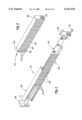
- FIG. 1 illustrates an exemplary dispensing system having a dispensing cabinet coupled to an auxiliary storage unit according to the invention.
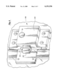
- FIG. 2 illustrates an item button switch panel assembly of the dispensing cabinet of FIG. 1.
- FIG. 3 illustrates an exploded view of the assembly of FIG. 2.
- FIG. 4 is a more detailed view of a lock on the auxiliary storage unit of FIG. 1.
- FIG. 5 illustrates an alternative embodiment of a dispensing system having a dispensing cabinet coupled to a lock on a closet according to the invention.
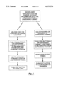
- FIG. 6 is a flowchart illustrating an exemplary method for dispensing items from the dispensing system of FIG. 1.
- the invention provides exemplary dispensing systems and methods which allow for the storage of various medical supply items in auxiliary storage locations while also controlling access to the items and maintaining an accurate accounting of their inventory levels. These features are obtained by coupling the auxiliary storage locations to dispensing cabinets which are selectively positioned at locations throughout a health care facility.
- the dispensing cabinets which may be used to control access to and maintain an accurate accounting of inventory levels of the supply items in the auxiliary storage locations may be constructed similar to those dispensing units described in U.S. Pat. No. 5,745,336, and co-pending U.S. application Ser. Nos. 08/250,223, filed May 27, 1994; U.S. Pat. No. 5,805,455; and U.S. Pat. No. 5,805,456, the disclosures of which are incorporated herein by reference.
- the supplies stored in the auxiliary storage locations will typically comprise those supplies which are too large or bulky to fit within such dispensing cabinets.
- such items may include crutches, adult diapers, "egg crate" foam pads, bed pans, and the like.
- essentially any type of item may be stored within the auxiliary storage locations.
- the dispensing cabinets and auxiliary storage locations will be employed to store a wide variety of medical supply items, including pharmaceutical items.
- the dispensing cabinets of the invention may be coupled to a wide variety of auxiliary storage locations, including other dispensing cabinets, closets, rooms, corridors, and the like.
- Such storage locations preferably include a door, drawer, or the like which must be opened in order to gain access to the interior of the auxiliary storage location.
- Locks are preferably provided to selectively prevent access to the items within the auxiliary storage locations.
- the locks of the auxiliary storage locations may be coupled to the dispensing cabinets in a variety of ways, including by an electrical cable, by a wireless transmitter, infra-red coupling, and the like.
- the invention provides exemplary techniques for controlling operation of such locks based on information input into a processor of the dispensing cabinet.
- auxiliary storage space may be secured by use of a lock which is operated by entering information into existing dispensing cabinets.
- the invention further provides for the use of item sensors on the dispensing cabinets which may be operated to record removal or addition of items from or to the auxiliary storage location. In this way, accurate inventory levels may be maintained for the items within the auxiliary storage locations using the processors within existing dispensing cabinets.
- Dispensing system 10 comprises a dispensing cabinet 12 and an auxiliary storage unit 14. As shown, dispensing cabinet 12 is similar to the dispensing cabinet described in U.S. Pat. No. 5,745,366, previously incorporated by reference. However, it will be appreciated that dispensing cabinet 12 may be configured to have other arrangements as previously described. For convenience of illustration, system 10 will be described in connection with the particular arrangement of dispensing cabinet 12.
- Dispensing cabinet 12 includes a supply zone 16 and a pharmaceutical zone 18.
- Supply zone 16 includes a plurality of shelves 20 that are subdivided into a plurality of storage locations.
- a plurality of touch-sensitive item buttons 22 are provided on each shelf 20 for recording the transfer of an item to or from the storage location on shelf 20 simply by touching the item button once for each item added to or removed from the storage location as described in U.S. Pat. No. 5,745,366.
- Dispensing cabinet 12 further includes a processor 24 that is in communication with buttons 22 for recording transfer information as just described. Processor 24 is also employed to record transfer and other information for pharmaceutical zone 18.
- a door 26 is disposed over supply zone 16.
- An internal lock (not shown) may optionally be provided to maintain door 26 locked. After appropriate information has been entered into processor 24, door 26 will be unlocked to allow access to the items as described in greater detail hereinafter.
- Item buttons 22 are preferably configured to be illuminated so that they will serve as light indicators to help locate a particular item within supply zone 16. For example, if a user is unable to locate a particular item, the name of the item may be entered into processor 24 (or selected from a list of items stored in processor 24). The processor then sends a signal to light the particular button 22 which is adjacent the item that is to be removed. Alternatively, a visual indicator, such as an LED, may be positioned adjacent each button 22 to assist in locating a particular button 22.
- Pharmaceutical zone 18 includes a plurality of pull-out drawers 28.
- a door 30 is optionally provided over drawers 28.
- a lock (not shown) similar to the lock used with door 26 may be employed to prevent access to drawers 28 until the necessary information is input into processor 24. Similarly, locks may be provided to selectively prevent access to drawers 28 based on information input into processor 24.
- At least some of drawers 28 are provided with a plurality of bins 32 which may optionally be covered with a lid 34.
- Each of drawers 28 may include a touch-sensitive drawer button 36 which may be touched to produce a record of access to a particular drawer. Buttons 36 may also serve as a visual indicator to assist in locating the particular drawer having an item that is requested from processor 24.
- some of lids 34 may be provided with a lock to secure the lid in a closed position until receiving an unlock signal from processor 24.
- Dispensing cabinet 12 further includes a multi-array button switch panel 38 having an array of item buttons 40 which are associated with items stored within auxiliary storage unit 14.
- a door 42 may be disposed over switch panel 38.
- touch sensitive buttons on regular shelves 20 may be assigned to auxiliary items, but since this may in some cases render the shelf space above the row of buttons unusable, the compact, multi-button array panel 38 is preferred.
- switch panel 38 is part of an assembly 44 which includes a switch panel housing 46 and a pair of frame mounting brackets 48 which are employed to mount assembly 44 to dispensing cabinet 12.
- Assembly 44 further includes a switch panel controller 50 which is electrically wired to each of buttons 40.
- controller 50 is placed in electrical communication with processor 24 via a connector 52.
- Assembly 44 is conveniently configured so that it may be easily placed into existing dispensing units such as those described in U.S. Pat. No. 5,745,336 and U.S. Pat. No. 5,805,455, previously incorporated by reference.
- switch panel 38 includes 32 item buttons 40.
- item buttons 40 may be illuminated to help a user locate a particular item button as described in greater detail hereinafter.
- a visual indicator such as an LED, may be positioned adjacent each button 40 (typically within about one cm) to assist in locating a particular item button.
- Auxiliary storage unit 14 includes a plurality of shelves 54 and a door 56 to prevent access to items that are to be stored on shelves 54. Attached to unit 14 is a lock 58 to prevent opening of door 56. As best illustrated in FIG. 4, lock 58 comprises a latch 60 which is received into a latch pawl 62 to lock door 56 to auxiliary storage unit 14. Lock 58 further includes a housing 64 which includes a solenoid (not shown) which is operated upon receipt of an electrical signal to move latch 60 into and out of engagement with latch pawl 62.
- auxiliary storage unit 14 is electrically coupled to auxiliary storage unit 14 by a cable 66.
- lock 58 may be operated upon receipt of electrical signals generated by processor 24.
- a user may gain access to auxiliary storage unit 14 utilizing processor 24 of dispensing cabinet 12.
- auxiliary storage unit 14 may be constructed relatively inexpensively and be operated using more expensive components which are shared with dispensing cabinet 12.
- Item buttons 40 on switch panel 38 are configured to correspond to specific locations within auxiliary storage unit 14.
- auxiliary storage unit 14 includes eight shelves.
- the first row of item buttons 40 on switch panel 38 may be configured to correspond to the first two shelves in auxiliary storage unit 14, the second row to the next two shelves and so on.
- the remaining item buttons 40 would not be activated unless more storage locations were provided within auxiliary storage unit 14.
- Item buttons 40 are preferably constructed to operate in a manner similar to item buttons 22 in supply zone 16. More specifically, to record removal of an item from one of shelves 54, the user simply presses item button 14 a number of times corresponding to the number of items to be removed. In a similar manner, items may be restocked onto a particular shelf 54 and the transaction recorded by touching the associated item button 40 on dispensing cabinet 12 a number of times corresponding to the number of items to be restocked.
- auxiliary storage unit 14 is placed on wheels or casters 68 to allow it to be moved to different locations within the health care facility.
- the length of cable 66 may be adjusted to accommodate for the amount of separation from dispensing cabinet 12.
- a wireless transmitter and receiver may be employed to operate lock 58 based on information input into processor 24.
- lock 58 may be placed on a variety of doors so that dispensing cabinet 12 will be useful in connection with a wide variety of storage locations, including storage rooms, closets, cabinets, and the like.
- a user approaches dispensing cabinet 12 and enters user identification information, such as a user name and password, into processor 24.
- user identification information such as a user name and password
- the user also enters in charge account information into processor 24.
- charge account information can include, for example, the patient's name or other entity who is responsible for the charges.
- a signal is sent to unlock lock 58 so that access to shelves 54 may be obtained by opening door 56.
- one or more doors of dispensing cabinet 12 may also be unlocked. For security reasons, some of the doors on dispensing cabinet 12 may be kept locked until additional information is entered.
- buttons 40 For example, if an item on top shelf 54 is to be removed, a first one of buttons 40 may be pressed once. For each additional item of the same type that is to be removed, button 40 is pressed a corresponding number of times. If another type of item is to be removed from another one of shelves 54, the corresponding item button 40 on switch panel 38 is pressed.
- the name of the item or other information may be entered into processor 24 which will cause the appropriate item button 40 to be lighted.
- a user may scroll through a list of item names produced by processor 24 to select the desired item.
- labels 105 will be typically affixed to the shelves. Also, the order of the items on the shelves will typically correspond to the order of the items designated on the switch panel 38. When finished, the user closes door 56.
- Lock 58 may further include an exit button 70 which the user pushes to indicate to processor 24 that the transaction is complete. Upon receipt of a signal from exit button 70, processor 24 sends a signal to lock 58 to lock door 56. Although shown as being disposed on lock 58, exit button 70 may be included on dispensing cabinet 12 as well.
- processor 24 may include a timer which is set to automatically lock 58 if exit button 70 is not pressed within a predetermined amount of time. In this way, if the user neglects to actuate exit button 70, lock 58 will lock to secure items within auxiliary storage unit 14. Similarly, the doors on dispensing cabinet 12 may be locked after a predetermined amount of time has expired.
- Processor 24 may optionally be configured to display information regarding the location of particular items stored within auxiliary storage unit 14, as well as the location of auxiliary storage unit 14 if not in view. Such information may be obtained by having the user enter into processor 24 the name of the item (or selecting the name from a list of names) and having processor 24 visually displaying a written description of the location on a screen 72.
- the user may also remove various items from dispensing cabinet 12 by opening the appropriate door and pressing item button 20 if the item is within supply zone 16 as described in U.S. Pat. No. 5,745,366. Similarly, items may be removed from pharmacy zone 18 in a manner described in U.S. Pat. No. 5,745,366.
- a user When returning unused items to the auxiliary storage unit 14, a user enters user identification information into processor 24 and then enters a return mode by pressing a return button 106 at the end of the switch panel 38. Actuation of the return button is preferably indicated by flashing the light indicators on that switch panel row, indicating that pushing the touch sensitive button will record a return, rather than an issue.
- the switch panel is returned to its normal mode, either by pushing the return button 106 a second time, or pushing a button on another switch panel, or when the user logs out of the machine. If a particular item is to be credited to a patient, the user may also enter charge account information into processor 24.
- the user When in return mode, the user simply presses item buttons 40 corresponding to the items that are to be returned, pressing each button the correct number of times corresponding to the number of items being returned. The items are then placed onto shelves 54 and exit button 70 is pressed to end the session.
- each button 40 may be provided next to each button 40. In this way, a return may be recorded simply by pressing the appropriate return button. However, due to the reduced circuitry, use of a return button at the end of each row is preferred.
- processor 24 may include a printer (not shown) which is able to generate a restock list containing a list of items that are to be restocked. Alternatively, such a restock list may be generated at a central location.
- item buttons 40 which correspond to items that to be restocked may be lighted in a flashing mode. In this way, the user may simply look at the restock list to determine the quantity of items that are to be replenished and then touch the corresponding flashing item buttons 40 a number of times corresponding to the number of items to be replenished.
- the processor 24 is sent information describing which items will be restocked and the quantity of each item that will be on the restock list.
- item buttons 40 or a visual indicator adjacent each button 40 which correspond to items to be restocked may be lit using a flashing mode.
- the restock technician touches the touch sensitive button 40 next to a particular flashing indicator, the light next to that button displays full on, to indicate that it has been selected.
- the quantity expected for that item is displayed on the screen of the processor 24. The quantity may be modified by the restock technician if it is not correct, but in most cases this will correspond to the quantity actually picked.
- the quantity is acknowledged by pressing the touch sensitive button just once, at which point the adjacent light goes out, indicating that that item has been replenished. This saves the restock technician from having to push the item button the number of times corresponding to the number of items being restocked. For large quantities, this saves considerable time. In addition the completion of the restocking process is clearly indicated by the fact that all the flashing lights are out.
- Processor 24 may also include a cycle count mode which allows a user to determine if there are any discrepancies between the records of processor 24 and the actual number of items held within the auxiliary storage unit 14. Such a task is preferably accomplished by generating a list of items and associated quantities that are held within auxiliary storage unit 14 from the information stored within processor 24. Using the list, the user visually inspects the items stored within auxiliary storage unit 14 to determine any discrepancies in the generated list. The user may then update the information stored in processor 24 to eliminate any discrepancies. Preferably, any discrepancies are corrected by having the user enter user identification information into processor 24 and then placing processor 24 into the cycle count mode. Item buttons 40 which correspond to items having a count discrepancy are then touched, and the correct quantity of the item stored in auxiliary storage unit 14 is entered into the processor 24, preferably by using a keypad 74.
- Dispensing system 76 comprises a dispensing cabinet 78 and a closet 80.
- dispensing cabinet 78 is similar to the dispensing cabinet described in U.S. Pat. No. 5,805,455, previously incorporated by reference.
- Dispensing cabinet 78 includes a plurality of shelves 82 holding items 84.
- Shelves 82 include a plurality of item buttons 86 for recording transfer of items to or from dispensing cabinet 78 in a manner similar to that previously described in connection with dispensing system 10. Adjacent each of item buttons 86 is a visual indicator 88 to assist the caregiver in locating a particular item.
- Dispensing cabinet 78 further includes a plurality of doors 90 which prevent access to items 84 until unlocked in a manner similar to that described in connection with dispensing cabinet 12.
- Dispensing cabinet 78 includes a processor 92 which is essentially identical to processor 24 of dispensing cabinet 12. Further, dispensing cabinet 78 includes a switch panel 94 having an array of item buttons 96 which correspond to particular storage locations within closet 80 in a manner similar to that described in connection with dispensing system 10.
- Closet 80 includes a door 98 having an associated lock 100 which is essentially identical to lock 58 of dispensing system 10.
- An electrical cable 102 is employed to electrically couple processor 92 to lock 100. In this way, access to closet 80 may be prevented until the input of appropriate information into processor 92 as previously described.
- Closet 80 includes a plurality of shelves 104 for holding various supply items. Transfer of items to or from shelves 104 are recorded by pressing the appropriate item buttons 96 on panel 94 in a manner similar to that described with dispensing system 10.
- Dispensing system 76 operates in a manner essentially identical to that previously described in connection with dispensing system 10. As such, access to items on shelves 104 is prevented until user identification information and charge account information are entered into processor 92 which will cause lock 100 to unlock. At the same time, various items may be removed from dispensing cabinet 78 and their removal recorded by operation of item buttons 86.
- dispensing cabinet 78 may be used to allow access into other rooms which have a lock similar to lock 100.
- existing storage space may easily and conveniently be adapted for use with an existing dispensing cabinet.
- controlled access to the items is provided, while at the same time allowing for easy and convenient recording of transfers of items by simply operating the appropriate item buttons on the dispensing cabinet.
Abstract
Description
Claims (29)
Priority Applications (1)
| Application Number | Priority Date | Filing Date | Title |
|---|---|---|---|
| US09/162,251 US6151536A (en) | 1998-09-28 | 1998-09-28 | Dispensing system and methods |
Applications Claiming Priority (1)
| Application Number | Priority Date | Filing Date | Title |
|---|---|---|---|
| US09/162,251 US6151536A (en) | 1998-09-28 | 1998-09-28 | Dispensing system and methods |
Publications (1)
| Publication Number | Publication Date |
|---|---|
| US6151536A true US6151536A (en) | 2000-11-21 |
Family
ID=22584827
Family Applications (1)
| Application Number | Title | Priority Date | Filing Date |
|---|---|---|---|
| US09/162,251 Expired - Lifetime US6151536A (en) | 1998-09-28 | 1998-09-28 | Dispensing system and methods |
Country Status (1)
| Country | Link |
|---|---|
| US (1) | US6151536A (en) |
Cited By (152)
| Publication number | Priority date | Publication date | Assignee | Title |
|---|---|---|---|---|
| WO2002003230A1 (en) * | 2000-06-30 | 2002-01-10 | Omnicell,Inc. | Dispensing system and method for dispensing items and providing information on the items over a network |
| WO2002099231A1 (en) | 2001-06-05 | 2002-12-12 | Baxter International Inc. | Dispensing method using wireless coupling |
| US20030019165A1 (en) * | 2001-05-25 | 2003-01-30 | Gallant Dennis J. | Patient care apparatus and method |
| US6539281B2 (en) * | 2001-04-23 | 2003-03-25 | Accenture Global Services Gmbh | Online medicine cabinet |
| US20030109956A1 (en) * | 2001-12-07 | 2003-06-12 | Spano Philip H. | Method of operating a dispensing cabinet |
| US20030120384A1 (en) * | 2000-11-07 | 2003-06-26 | David Haitin | Medication administration system |
| US6604019B2 (en) * | 1998-05-27 | 2003-08-05 | Nextrx Corporation | Automated pharmaceutical management and dispensing system |
| US20030164401A1 (en) * | 2002-02-26 | 2003-09-04 | Safety Syringes, Inc. | Systems and methods for tracking pharmaceuticals within a facility |
| US6658322B1 (en) * | 2000-05-05 | 2003-12-02 | Medselect Inc. | System and method for tracking medical items and supplies |
| US6662081B1 (en) * | 2000-06-08 | 2003-12-09 | Medport Llc | Medication regimen container and system |
| US20030232429A1 (en) * | 2002-06-17 | 2003-12-18 | Tsuneya Ohno | System for culturing human cells and tissues |
| US6684126B2 (en) * | 2000-01-18 | 2004-01-27 | Tosho, Inc. | Medicine storage apparatus |
| US6711458B1 (en) * | 1999-07-19 | 2004-03-23 | Apport Systems A/S | Handling system and indication system for same |
| US6735497B2 (en) * | 1999-09-22 | 2004-05-11 | Telepharmacy Solutions, Inc. | Systems and methods for dispensing medical products |
| US20040108795A1 (en) * | 2002-12-06 | 2004-06-10 | Meek Robert B. | High capacity drawer with mechanical indicator for a dispensing device |
| WO2004053620A2 (en) * | 2002-12-12 | 2004-06-24 | Mdg Medical, Inc. | Medication administration system |
| US6760643B2 (en) * | 1994-10-11 | 2004-07-06 | Omnicell, Inc. | Methods and apparatus for dispensing items |
| US20040181528A1 (en) * | 2003-03-11 | 2004-09-16 | Tirinato Jody Ann | Point-of-care inventory management system and method |
| US20040193317A1 (en) * | 2001-11-30 | 2004-09-30 | Richard Lunak | Filling a restocking package using a carousel |
| US20040225409A1 (en) * | 2003-05-08 | 2004-11-11 | Omnicell, Inc. | Secured dispensing cabinet and methods |
| US6868344B1 (en) | 2001-06-22 | 2005-03-15 | Vigilant Devices, Llc | Controlled substance analysis, wastage disposal and documentation system, apparatus and method |
| US6876902B2 (en) * | 2002-02-19 | 2005-04-05 | Aleks D. Nikolich | Automated supply cart and system |
| US20050080509A1 (en) * | 2003-10-08 | 2005-04-14 | Rippolone Joseph D. | Pipe storage and inventory control chest |
| US20050165559A1 (en) * | 2002-06-19 | 2005-07-28 | Vigilant Devices, Llc | Controlled substance analysis, wastage disposal and documentation system, apparatus and method |
| US20050224279A1 (en) * | 2004-04-09 | 2005-10-13 | Vecta Technology, L.P. | Accelerated weight drop configurable for use as a shear wave seismic energy source and a method of operation thereof |
| WO2005062877A3 (en) * | 2003-12-22 | 2005-11-17 | Precious Life Llc | Escape hood |
| US7028687B1 (en) * | 1999-08-26 | 2006-04-18 | Precious Life, Llc | Escape hood |
| US20060129273A1 (en) * | 2004-11-24 | 2006-06-15 | Steve Kirsch | Medication tray having a light grid over a surface thereof |
| US20060129274A1 (en) * | 2004-11-24 | 2006-06-15 | Steve Kirsch | Computerized method and system for loading and/or unloading a tray using laser scanning technology |
| US20060259188A1 (en) * | 2005-05-03 | 2006-11-16 | Berg Michel J | Items dispenser |
| US20060259187A1 (en) * | 2005-05-03 | 2006-11-16 | Berg Michel J | System and method for interactive items dispenser |
| US20060266770A1 (en) * | 2005-05-26 | 2006-11-30 | Fitzgerald Robert M | Portable dispensers comprising a mobile dispenser and mobile storage cartridge |
| US7197482B2 (en) * | 2001-04-19 | 2007-03-27 | Honeywell International Inc. | Method and apparatus for customer storefront operations |
| US20070119930A1 (en) * | 1999-10-29 | 2007-05-31 | Michael Jordan | Automated will call system |
| US20070135965A1 (en) * | 2005-12-09 | 2007-06-14 | Cardinal Health 301, Inc. | System and method for storing items and tracking item usage |
| US7258249B1 (en) | 2000-05-05 | 2007-08-21 | Automed Technologies, Inc. | Medical item storage cabinet and method |
| US20070262147A1 (en) * | 2006-05-10 | 2007-11-15 | Mckesson Automation Inc. | System, method and corresponding apparatus for storing, retrieving and delivering unit dose blisters |
| WO2008072213A2 (en) * | 2006-12-15 | 2008-06-19 | Timothy John Fleischer | Paper management system |
| US20080149656A1 (en) * | 2004-10-28 | 2008-06-26 | Yuyama Mfg. Co., Ltd | Dispensing Support Device and Dispensing Support Method |
| US7463947B1 (en) * | 2000-05-05 | 2008-12-09 | Automed Technologies, Inc. | Medical item storage cabinet and method |
| US20080319576A1 (en) * | 2007-06-19 | 2008-12-25 | Omnicell, Inc. | Status designation for dispensing device systems and methods |
| US20090045152A1 (en) * | 2004-10-15 | 2009-02-19 | Shoji Yuyama | Medicine cart |
| US20090187274A1 (en) * | 2007-01-22 | 2009-07-23 | John David Higham | Pharmaceutical dispensing system with coordinate guidance |
| US7596427B1 (en) | 2000-05-05 | 2009-09-29 | Automed Technologies, Inc. | Medical item storage cabinet and method |
| US20100029117A1 (en) * | 2008-08-01 | 2010-02-04 | Verizon Corporate Services Group Inc. | Computer-controlled connector-panel system |
| US7661591B2 (en) | 2000-10-20 | 2010-02-16 | Promega Corporation | RF point of sale and delivery method and system using communication with remote computer and having features to read a large number of RF tags |
| US20100049361A1 (en) * | 2007-01-19 | 2010-02-25 | Groupe Domedic Inc | Medication dispensing system and method |
| US7689316B1 (en) | 2000-05-05 | 2010-03-30 | Automed Technologies, Inc. | Medical item storage cabinet and method |
| US7710275B2 (en) | 2007-03-16 | 2010-05-04 | Promega Corporation | RFID reader enclosure and man-o-war RFID reader system |
| US7735732B2 (en) | 2000-10-20 | 2010-06-15 | Promega Corporation | Radio frequency identification method and system of distributing products |
| US20100176699A1 (en) * | 2009-01-09 | 2010-07-15 | Amerisourcebergen Corporation | Medication cabinetry |
| US20100179890A1 (en) * | 2009-01-14 | 2010-07-15 | Cianciotto Jr Michael S | Tool inventory management system |
| US20100198620A1 (en) * | 2009-01-30 | 2010-08-05 | Omnicell, Inc. | Tissue tracking |
| US20100198398A1 (en) * | 2004-05-19 | 2010-08-05 | Yuyama Mfg. Co., Ltd. | Medicine dispensing device |
| US20100228392A1 (en) * | 2009-03-03 | 2010-09-09 | McKesson Automation Inc., | Medication Storage And Dispensing Unit Having A Vial Dispenser |
| US7865263B2 (en) | 2003-11-26 | 2011-01-04 | Mckesson Automation, Inc. | Integrated suite of medical tools |
| US20110016026A1 (en) * | 2009-07-14 | 2011-01-20 | Cardinal Health 303, Inc. | Portable inventory tracking system |
| US7982612B2 (en) | 2009-02-20 | 2011-07-19 | Mckesson Automation Inc. | Methods, apparatuses, and computer program products for monitoring a volume of fluid in a flexible fluid bag |
| US20110202170A1 (en) * | 2010-02-09 | 2011-08-18 | Dawes Dennis K | Access and inventory control for climate controlled storage |
| US8009913B2 (en) | 2007-05-29 | 2011-08-30 | Mckesson Automation, Inc. | System, method, apparatus and computer program product for capturing human-readable text displayed on a unit dose package |
| US8006903B2 (en) | 2007-12-28 | 2011-08-30 | Mckesson Automation, Inc. | Proximity-based inventory management system using RFID tags to aid in dispensing and restocking inventory |
| WO2011144770A1 (en) * | 2010-05-19 | 2011-11-24 | Save-Dummy, S.L. | Intelligent first-aid kit |
| US8094028B2 (en) | 2007-12-28 | 2012-01-10 | Mckesson Automation, Inc. | Radio frequency alignment object, carriage and associated method of storing a product associated therewith |
| US8195328B2 (en) | 2003-09-19 | 2012-06-05 | Vesta Medical, Llc | Combination disposal and dispensing apparatus and method |
| US8234128B2 (en) | 2002-04-30 | 2012-07-31 | Baxter International, Inc. | System and method for verifying medical device operational parameters |
| US20120232692A1 (en) * | 2011-03-11 | 2012-09-13 | Jane Win-Shih Liu | Local access delivery control system |
| US8280550B2 (en) | 2008-06-17 | 2012-10-02 | Omnicell, Inc. | Cabinet with remote integration |
| US20120253510A1 (en) * | 2011-03-31 | 2012-10-04 | Mckesson Automation Inc. | Storage devices, systems, and methods for facilitating medication dispensing and restocking |
| WO2012151293A1 (en) | 2011-05-02 | 2012-11-08 | Omnicell, Inc. | Dispensing cabinet with articulating arm |
| US20120330462A1 (en) * | 2011-06-22 | 2012-12-27 | Ralf Maroney | Computer-Controlled Common Access Cabinet |
| US8342400B1 (en) * | 2007-09-13 | 2013-01-01 | Diebold, Incorporated | Systems controlled by data bearing records for maintaining inventory data |
| US8400277B2 (en) | 2009-03-30 | 2013-03-19 | Mckesson Automation Inc. | Methods, apparatuses, and computer program products for monitoring a transfer of fluid between a syringe and a fluid reservoir |
| US8405875B2 (en) | 2009-03-23 | 2013-03-26 | Mckesson Automation Inc. | Visibly-coded medication label and associated method, apparatus and computer program product for providing same |
| US20130079924A1 (en) * | 2011-09-23 | 2013-03-28 | Mckesson Automation Inc. | Systems, methods and computer program product for streamlined medication dispensing |
| US8453548B2 (en) | 2010-03-23 | 2013-06-04 | Mckesson Automation Inc. | Apparatuses for cutting a unit dose blister card |
| US8474691B2 (en) | 2010-03-31 | 2013-07-02 | Mckesson Automation Inc. | System, apparatus, method and computer-readable storage medium for generating medication labels |
| US8527090B2 (en) | 2010-03-30 | 2013-09-03 | Mckesson Automation Inc. | Method, computer program product and apparatus for facilitating storage and/or retrieval of unit dose medications |
| US8588966B2 (en) | 2009-01-09 | 2013-11-19 | Automed Technologies, Inc. | Cabinet system |
| US8588964B2 (en) | 2011-03-30 | 2013-11-19 | Mckesson Automation Inc. | Storage devices, systems, and methods for dispensing medications |
| US8593278B2 (en) | 2010-03-29 | 2013-11-26 | Mckesson Automation Inc. | Medication storage device usage status notifications |
| US8644982B2 (en) | 2009-09-30 | 2014-02-04 | Mckesson Automation Inc. | Unit dose packaging and associated robotic dispensing system and method |
| US8640586B2 (en) | 2010-03-23 | 2014-02-04 | Mckesson Automation Inc. | Method and apparatus for facilitating cutting of a unit dose blister card |
| US8650042B2 (en) | 2011-09-30 | 2014-02-11 | Mckesson Automation Inc. | Case and medication tracking |
| US8660687B2 (en) | 2010-03-30 | 2014-02-25 | Mckesson Automation Inc. | Medication bin having an electronic display and an associated method and computer program product |
| US8662606B2 (en) | 2011-03-17 | 2014-03-04 | Mckesson Automation Inc. | Drawer assembly and associated method for controllably limiting the slideable extension of a drawer |
| US8694162B2 (en) | 2010-12-20 | 2014-04-08 | Mckesson Automation, Inc. | Methods, apparatuses and computer program products for utilizing near field communication to guide robots |
| US8700210B2 (en) | 2011-09-29 | 2014-04-15 | Aesynt Incorporated | Systems, methods and computer program products for visually emphasizing portions of a medication storage device |
| US8701931B2 (en) | 2011-03-30 | 2014-04-22 | Aesynt Incorporated | Medication dispensing cabinet and associated drawer assembly having pockets with controllably openable lids |
| US8738383B2 (en) | 2007-06-07 | 2014-05-27 | Aesynt Incorporated | Remotely and interactively controlling semi-automatic devices |
| US20140148947A1 (en) * | 2012-11-29 | 2014-05-29 | Distributrices Médicales B.H.L. Inc. | Method and system for article management |
| US8744621B2 (en) | 2009-01-09 | 2014-06-03 | Automed Technologies, Inc. | Medical cabinet access belt optimization system |
| US8746908B2 (en) | 2010-01-27 | 2014-06-10 | Automed Technologies, Inc. | Medical supply cabinet with lighting features |
| US8755930B2 (en) | 2012-03-30 | 2014-06-17 | Aesynt Incorporated | Method, apparatus, and computer program product for optimization of item location in an automated storage system |
| US8775196B2 (en) | 2002-01-29 | 2014-07-08 | Baxter International Inc. | System and method for notification and escalation of medical data |
| US8807389B2 (en) | 2012-03-30 | 2014-08-19 | Aesynt Incorporated | Item dispensing unit |
| US8869663B2 (en) | 2009-03-25 | 2014-10-28 | Aesynt Incorporated | System, method and corresponding apparatus for detecting perforations on a unit dose blister card |
| US8869364B2 (en) | 2012-06-25 | 2014-10-28 | Aesynt Incorporated | Material separating tool |
| US8869667B2 (en) | 2009-12-04 | 2014-10-28 | Aesynt Incorporated | System, method and corresponding apparatus for singulating a unit dose blister card |
| US8929641B2 (en) | 2009-03-17 | 2015-01-06 | Aesynt Incorporated | System and method for determining the orientation of a unit dose package |
| US8983655B2 (en) | 2012-03-26 | 2015-03-17 | Aesynt Incorporated | Automated dispensing system and method |
| US20150078536A1 (en) * | 2012-12-03 | 2015-03-19 | Mylan Inc. | System and method for medicament storage, dispensing, and administration |
| US9037285B2 (en) | 2002-08-09 | 2015-05-19 | Mckesson Automation Systems, Inc. | Automated apparatus and method for filling vials |
| US9123195B2 (en) | 2012-06-29 | 2015-09-01 | Aesynt Incorporated | Modular, multi-orientation conveyor |
| US9121197B2 (en) | 2009-01-09 | 2015-09-01 | Automed Technologies, Inc. | Cabinet system with improved drawer security |
| US9150119B2 (en) | 2013-03-15 | 2015-10-06 | Aesynt Incorporated | Apparatuses, systems, and methods for anticipating and delivering medications from a central pharmacy to a patient using a track based transport system |
| US9171246B2 (en) | 2012-06-29 | 2015-10-27 | Aesynt Incorporated | System, methods, apparatuses, and computer program products for detecting that an object has been accessed |
| US9195803B2 (en) | 2013-03-28 | 2015-11-24 | Aesynt Incorporated | Systems, methods, apparatuses, and computer program products for providing controlled access to intravenous bags |
| US9324051B2 (en) | 2012-11-19 | 2016-04-26 | Omnicell, Inc. | Storage cabinet with multiple RFID readers |
| US9355220B2 (en) | 2011-05-02 | 2016-05-31 | Omnicell, Inc. | Medication dispensing cabinet systems and methods |
| US9365315B2 (en) | 2014-01-28 | 2016-06-14 | Omnicell, Inc. | Versatile lighting system for dispensing cabinets |
| US9399543B2 (en) | 2010-07-14 | 2016-07-26 | Parata Systems, Llc | Automated pharmacy system for dispensing unit doses of pharmaceuticals and the like |
| US9412217B2 (en) | 2011-03-31 | 2016-08-09 | Aesynt Incorporated | Medication dispensing apparatus having conveyed carriers |
| US20160259904A1 (en) * | 2015-03-03 | 2016-09-08 | Abide Technologies, Llc | System and method for providing dispensing security for controlled substances within a care facility |
| US9443371B2 (en) | 2013-03-27 | 2016-09-13 | Aesynt Incorporated | Medication dispensing cabinet, computing device and associated method for measuring the force applied to a drawer |
| US9511945B2 (en) | 2012-10-12 | 2016-12-06 | Aesynt Incorporated | Apparatuses, systems, and methods for transporting medications from a central pharmacy to a patient in a healthcare facility |
| US9579245B2 (en) | 2013-07-26 | 2017-02-28 | Helmer, Inc. | Medical products storage device including access control |
| US20170061095A1 (en) * | 2015-08-31 | 2017-03-02 | Carstens, Inc. | System and method for bedside medication dispensing |
| US9626817B2 (en) | 2013-03-29 | 2017-04-18 | Aesynt Incorporated | Apparatuses, systems, and methods for storing and dispensing medication proximate a patient |
| WO2017066741A1 (en) | 2015-10-15 | 2017-04-20 | Omnicell, Inc. | Medical equipment with diversion mechanism |
| US9643770B2 (en) | 2012-12-03 | 2017-05-09 | Mylan Inc. | System and method for medicament storage, dispensing, and administration |
| US9715671B2 (en) | 2011-05-02 | 2017-07-25 | Omnicell, Inc. | Facility-wide medication management systems |
| US9814828B2 (en) | 2013-03-15 | 2017-11-14 | Aesynt Incorporated | Method and apparatus for preparing and monitoring an intravenous fluid bag |
| US9818251B2 (en) | 2015-02-27 | 2017-11-14 | Omnicell, Inc. | Unit dose dispensing systems and methods |
| US9884695B2 (en) | 2013-03-28 | 2018-02-06 | Aesynt Incorporated | Compartment configured for presentation of stored articles |
| US9910965B2 (en) | 2011-09-16 | 2018-03-06 | Aesynt Incorporated | Systems, methods and computer program product for monitoring interactions with a medication storage device |
| US10016554B2 (en) | 2008-07-09 | 2018-07-10 | Baxter International Inc. | Dialysis system including wireless patient data |
| US10045909B2 (en) | 2012-03-30 | 2018-08-14 | Aesynt Incorporated | Storage apparatus with support structures |
| US10061899B2 (en) | 2008-07-09 | 2018-08-28 | Baxter International Inc. | Home therapy machine |
| US10115073B2 (en) | 2016-03-09 | 2018-10-30 | WaveMark, Inc. | Medical cabinet communication system and methods |
| US10173008B2 (en) | 2002-01-29 | 2019-01-08 | Baxter International Inc. | System and method for communicating with a dialysis machine through a network |
| US10186100B2 (en) | 2016-02-09 | 2019-01-22 | Omnicell, Inc. | Relay box |
| EP3407276A3 (en) * | 2017-05-02 | 2019-01-30 | Inventor-e Limited | Asset tag and methods and devices for restocking and asset tracking |
| US20190060176A1 (en) | 2017-08-31 | 2019-02-28 | Omnicell, Inc. | Unit dose dispensing mechanisms |
| US10325234B2 (en) * | 2014-07-30 | 2019-06-18 | Walmart Apollo, Llc | Systems and methods for demand tracking of products based on sales and controlling restocking as a function of the determined demand in a retail environment |
| US10347374B2 (en) | 2008-10-13 | 2019-07-09 | Baxter Corporation Englewood | Medication preparation system |
| WO2019152277A1 (en) | 2018-01-30 | 2019-08-08 | Omnicell, Inc. | Relay tray |
| USRE47599E1 (en) | 2000-10-20 | 2019-09-10 | Promega Corporation | RF point of sale and delivery method and system using communication with remote computer and having features to read a large number of RF tags |
| US10646405B2 (en) | 2012-10-26 | 2020-05-12 | Baxter Corporation Englewood | Work station for medical dose preparation system |
| US10663218B2 (en) | 2017-11-17 | 2020-05-26 | Omnicell, Inc. | Dispensing system with temperature controlled drawers |
| US10726099B2 (en) | 2012-12-19 | 2020-07-28 | Capsa Solutions Llc | System and method for providing real time control of pharmaceuticals |
| US10818387B2 (en) | 2014-12-05 | 2020-10-27 | Baxter Corporation Englewood | Dose preparation data analytics |
| US10971257B2 (en) | 2012-10-26 | 2021-04-06 | Baxter Corporation Englewood | Image acquisition for medical dose preparation system |
| US11076710B2 (en) * | 2014-10-24 | 2021-08-03 | Leer, Inc. | Merchandiser with on-product financial payment system |
| US11107574B2 (en) | 2014-09-30 | 2021-08-31 | Baxter Corporation Englewood | Management of medication preparation with formulary management |
| US11348672B2 (en) | 2017-12-29 | 2022-05-31 | Cerner Innovation, Inc. | Medical order entry integration with automated dispensing systems |
| US11367533B2 (en) | 2014-06-30 | 2022-06-21 | Baxter Corporation Englewood | Managed medical information exchange |
| US11426329B2 (en) | 2019-11-12 | 2022-08-30 | Omnicell, Inc. | Dispensing systems and methods for prefilled syringes |
| US11495334B2 (en) | 2015-06-25 | 2022-11-08 | Gambro Lundia Ab | Medical device system and method having a distributed database |
| US11516183B2 (en) | 2016-12-21 | 2022-11-29 | Gambro Lundia Ab | Medical device system including information technology infrastructure having secure cluster domain supporting external domain |
| US11536506B2 (en) | 2018-09-12 | 2022-12-27 | Omnicell, Inc. | Temperature controlled dispense drawer |
| US11575673B2 (en) | 2014-09-30 | 2023-02-07 | Baxter Corporation Englewood | Central user management in a distributed healthcare information management system |
| US11948112B2 (en) | 2015-03-03 | 2024-04-02 | Baxter Corporation Engelwood | Pharmacy workflow management with integrated alerts |
Citations (72)
| Publication number | Priority date | Publication date | Assignee | Title |
|---|---|---|---|---|
| US35743A (en) * | 1862-07-01 | Improvement in wagon-standards | ||
| US3556342A (en) * | 1969-05-05 | 1971-01-19 | Joseph S Guarr | Medicine dispensing apparatus |
| US3715148A (en) * | 1971-06-03 | 1973-02-06 | C Beals | Medicine dispensing cabinet |
| US3744867A (en) * | 1972-04-03 | 1973-07-10 | J Shaw | Programmed dispenser |
| US3762601A (en) * | 1972-08-14 | 1973-10-02 | Laughlin J Mc | Cabinet for dispensing medicines at predetermined times |
| US3917045A (en) * | 1974-04-25 | 1975-11-04 | Robert L Williams | Drug dispensing apparatus |
| US3998356A (en) * | 1975-08-28 | 1976-12-21 | Arthur A. Bennett, Jr. | Electronic system for article dispensing apparatus |
| US4019793A (en) * | 1975-03-14 | 1977-04-26 | Gerding Paul W | Pharmaceutical dosage distribution apparatus |
| US4071747A (en) * | 1976-09-27 | 1978-01-31 | Pantanella Anthony C | Drawer illuminating device |
| US4114965A (en) * | 1976-11-04 | 1978-09-19 | Trans-Aid Corporation | Medication dispensing cart |
| SU656613A1 (en) * | 1977-11-01 | 1979-04-15 | Тартуский государственный университет | Device for storing and serving medicines |
| US4179724A (en) * | 1976-04-02 | 1979-12-18 | Bonhomme F R | Cabinets for electrical or electronic equipment |
| US4209211A (en) * | 1978-09-28 | 1980-06-24 | Umc Industries, Inc. | Vendor with door and shelf interlock |
| US4267942A (en) * | 1979-06-20 | 1981-05-19 | John B. Wick, Jr. | Pharmaceutical dispensing cabinet |
| US4360125A (en) * | 1980-03-10 | 1982-11-23 | Medtronic, Inc. | Medication inventory device |
| US4382688A (en) * | 1981-01-26 | 1983-05-10 | Machamer Roy J | Timed medication dispenser |
| US4473884A (en) * | 1982-01-08 | 1984-09-25 | Sybron Corporation | Electronic medication dispensing system |
| US4575719A (en) * | 1983-10-14 | 1986-03-11 | Avicom International, Inc. | Controlled access storage system |
| US4626105A (en) * | 1986-03-04 | 1986-12-02 | Miller Larry D | Medication organizer |
| US4635053A (en) * | 1983-09-06 | 1987-01-06 | Banks Edward J K | Apparatus for supervising access to individual items |
| US4640560A (en) * | 1984-12-17 | 1987-02-03 | Blum Richard S | Pill dispenser |
| US4691470A (en) * | 1986-05-12 | 1987-09-08 | Woodstream Corporation | Lighted tackle box |
| US4695954A (en) * | 1984-10-31 | 1987-09-22 | Rose Robert J | Modular medication dispensing system and apparatus utilizing portable memory device |
| US4717042A (en) * | 1986-05-28 | 1988-01-05 | Pyxis Corporation | Medicine dispenser for home health care |
| US4737910A (en) * | 1985-10-15 | 1988-04-12 | Kimbrow Ronald H | Apparatus for tracking inventory |
| US4783740A (en) * | 1985-12-26 | 1988-11-08 | Kabushiki Kaisha Toshiba | Inventory management system |
| US4785969A (en) * | 1986-11-10 | 1988-11-22 | Pyxis Corporation | Medication dispensing system |
| US4803604A (en) * | 1988-02-26 | 1989-02-07 | Nichols Nancie L | Illuminated serving tray |
| US4811764A (en) * | 1987-10-19 | 1989-03-14 | Mclaughlin John T | Medication dispenser station |
| US4813753A (en) * | 1987-04-06 | 1989-03-21 | Drustar Inc. | Drug control and dispensing assembly |
| US4847764A (en) * | 1987-05-21 | 1989-07-11 | Meditrol, Inc. | System for dispensing drugs in health care institutions |
| US4866661A (en) * | 1986-03-26 | 1989-09-12 | Prins Maurits L De | Computer controlled rental and sale system and method for a supermarket and the like |
| US4942275A (en) * | 1988-05-12 | 1990-07-17 | Esi Companies, Inc. | Control panel face |
| US4962491A (en) * | 1988-10-13 | 1990-10-09 | Schaeffer Theodore S | Medicament dispenser and medical information storage apparatus |
| US4967928A (en) * | 1988-06-09 | 1990-11-06 | Carter Cheryl L | Inventory control including individual patient listing and medical chart record for medication cart |
| FR2650426A1 (en) * | 1989-07-25 | 1991-02-01 | Int New Deal | Aide-memoire for programmed display of the dosage instructions for a medication at a defined time |
| US5014875A (en) * | 1989-03-01 | 1991-05-14 | Pyxis Corporation | Medication dispenser station |
| US5047948A (en) * | 1989-04-25 | 1991-09-10 | Turner Joseph D | Medication dispensing system |
| US5055660A (en) * | 1988-06-16 | 1991-10-08 | Avicom International, Inc. | Portable transaction monitoring unit for transaction monitoring and security control systems |
| US5069511A (en) * | 1990-05-10 | 1991-12-03 | Herman Miller, Inc. | Pharmaceutical cabinet locking arrangement |
| US5200891A (en) * | 1990-01-17 | 1993-04-06 | Bruce A. Kehr | Electronic medication dispensing method |
| US5242223A (en) * | 1992-07-13 | 1993-09-07 | Thomas Koves | Dividers for drawers or the like |
| US5257693A (en) * | 1992-07-15 | 1993-11-02 | Diane Kwasniak | Drug drawer tray |
| US5259668A (en) * | 1991-03-01 | 1993-11-09 | Artromick International Inc. | Cart for medication |
| US5263596A (en) * | 1991-12-02 | 1993-11-23 | Williams David R | Medication dispenser station sub-assembly |
| US5267174A (en) * | 1989-09-29 | 1993-11-30 | Healthtech Services Corp. | Interactive medication delivery system |
| US5276810A (en) * | 1990-06-27 | 1994-01-04 | Victor Company Of Japan, Ltd. | Information item selection apparatus producing multi-channel output signals |
| US5291191A (en) * | 1992-03-20 | 1994-03-01 | Moore Don L | Medicine dispenser |
| US5292029A (en) * | 1989-11-08 | 1994-03-08 | Pearson Walter G | Patient medication dispensing and associated record |
| US5314243A (en) * | 1992-12-04 | 1994-05-24 | Automated Healthcare, Inc. | Portable nursing center |
| US5346297A (en) * | 1993-01-04 | 1994-09-13 | Colson Jr Angus R | Auxiliary storage and dispensing unit |
| US5355289A (en) * | 1993-08-02 | 1994-10-11 | Krenn Ronald J | Lighted serving tray |
| US5381315A (en) * | 1993-03-09 | 1995-01-10 | Fujitsu Limited | Shelf assembly in electronic switching system |
| WO1995003587A1 (en) * | 1993-07-21 | 1995-02-02 | Omnicell Technologies, Inc. | Methods and apparatus for dispensing items |
| US5392951A (en) * | 1993-05-20 | 1995-02-28 | Lionville Systems, Inc. | Drawer operating system |
| US5408443A (en) * | 1992-08-19 | 1995-04-18 | Polypharm Corp. | Programmable medication dispensing system |
| US5459648A (en) * | 1994-09-02 | 1995-10-17 | Courtney; Glenn H. | Illuminated utility box |
| US5460294A (en) * | 1994-05-12 | 1995-10-24 | Pyxis Corporation | Single dose pharmaceutical dispenser subassembly |
| CA2130252A1 (en) * | 1994-08-16 | 1996-02-17 | Syl Medwid | Automatic medication dispenser |
| US5502944A (en) * | 1993-12-03 | 1996-04-02 | Owen Healthcare, Inc. | Medication dispenser system |
| US5537313A (en) * | 1993-11-22 | 1996-07-16 | Enterprise Systems, Inc. | Point of supply use distribution process and apparatus |
| WO1996021925A1 (en) * | 1995-01-13 | 1996-07-18 | Omnicell Technologies, Inc. | Speech controlled dispensing or collecting device |
| WO1997014104A1 (en) * | 1995-10-10 | 1997-04-17 | Omnicell Technologies, Inc. | Pharmaceutical dispensing device and methods |
| US5661978A (en) * | 1994-12-09 | 1997-09-02 | Pyxis Corporation | Medical dispensing drawer and thermoelectric device for cooling the contents therein |
| US5664856A (en) * | 1994-02-17 | 1997-09-09 | Snap-On Technologies, Inc. | Stackable divided drawer partition |
| US5673983A (en) * | 1995-04-21 | 1997-10-07 | Metro Industries, Inc. | Cassette assembly and unit dose medication cart using the cassette assembly |
| US5745366A (en) * | 1994-07-14 | 1998-04-28 | Omnicell Technologies, Inc. | Pharmaceutical dispensing device and methods |
| WO1998026746A2 (en) * | 1996-12-05 | 1998-06-25 | Omnicell Technologies, Inc. | Replacement liner and methods for dispensing device |
| US5805456A (en) * | 1994-07-14 | 1998-09-08 | Omnicell Technologies, Inc. | Device and method for providing access to items to be dispensed |
| US5805455A (en) * | 1993-07-21 | 1998-09-08 | Omincell Technologies, Inc. | Methods for dispensing items |
| US5905653A (en) * | 1994-07-14 | 1999-05-18 | Omnicell Technologies, Inc. | Methods and devices for dispensing pharmaceutical and medical supply items |
| US6011999A (en) * | 1997-12-05 | 2000-01-04 | Omnicell Technologies, Inc. | Apparatus for controlled dispensing of pharmaceutical and medical supplies |
-
1998
- 1998-09-28 US US09/162,251 patent/US6151536A/en not_active Expired - Lifetime
Patent Citations (76)
| Publication number | Priority date | Publication date | Assignee | Title |
|---|---|---|---|---|
| US35743A (en) * | 1862-07-01 | Improvement in wagon-standards | ||
| US3556342A (en) * | 1969-05-05 | 1971-01-19 | Joseph S Guarr | Medicine dispensing apparatus |
| US3715148A (en) * | 1971-06-03 | 1973-02-06 | C Beals | Medicine dispensing cabinet |
| US3744867A (en) * | 1972-04-03 | 1973-07-10 | J Shaw | Programmed dispenser |
| US3762601A (en) * | 1972-08-14 | 1973-10-02 | Laughlin J Mc | Cabinet for dispensing medicines at predetermined times |
| US3917045A (en) * | 1974-04-25 | 1975-11-04 | Robert L Williams | Drug dispensing apparatus |
| US4019793A (en) * | 1975-03-14 | 1977-04-26 | Gerding Paul W | Pharmaceutical dosage distribution apparatus |
| US3998356A (en) * | 1975-08-28 | 1976-12-21 | Arthur A. Bennett, Jr. | Electronic system for article dispensing apparatus |
| US4179724A (en) * | 1976-04-02 | 1979-12-18 | Bonhomme F R | Cabinets for electrical or electronic equipment |
| US4071747A (en) * | 1976-09-27 | 1978-01-31 | Pantanella Anthony C | Drawer illuminating device |
| US4114965A (en) * | 1976-11-04 | 1978-09-19 | Trans-Aid Corporation | Medication dispensing cart |
| SU656613A1 (en) * | 1977-11-01 | 1979-04-15 | Тартуский государственный университет | Device for storing and serving medicines |
| US4209211A (en) * | 1978-09-28 | 1980-06-24 | Umc Industries, Inc. | Vendor with door and shelf interlock |
| US4267942A (en) * | 1979-06-20 | 1981-05-19 | John B. Wick, Jr. | Pharmaceutical dispensing cabinet |
| US4360125A (en) * | 1980-03-10 | 1982-11-23 | Medtronic, Inc. | Medication inventory device |
| US4382688A (en) * | 1981-01-26 | 1983-05-10 | Machamer Roy J | Timed medication dispenser |
| US4473884A (en) * | 1982-01-08 | 1984-09-25 | Sybron Corporation | Electronic medication dispensing system |
| US4635053A (en) * | 1983-09-06 | 1987-01-06 | Banks Edward J K | Apparatus for supervising access to individual items |
| US4575719A (en) * | 1983-10-14 | 1986-03-11 | Avicom International, Inc. | Controlled access storage system |
| US4695954A (en) * | 1984-10-31 | 1987-09-22 | Rose Robert J | Modular medication dispensing system and apparatus utilizing portable memory device |
| US4640560A (en) * | 1984-12-17 | 1987-02-03 | Blum Richard S | Pill dispenser |
| US4737910A (en) * | 1985-10-15 | 1988-04-12 | Kimbrow Ronald H | Apparatus for tracking inventory |
| US4783740A (en) * | 1985-12-26 | 1988-11-08 | Kabushiki Kaisha Toshiba | Inventory management system |
| US4626105A (en) * | 1986-03-04 | 1986-12-02 | Miller Larry D | Medication organizer |
| US4866661A (en) * | 1986-03-26 | 1989-09-12 | Prins Maurits L De | Computer controlled rental and sale system and method for a supermarket and the like |
| US4691470A (en) * | 1986-05-12 | 1987-09-08 | Woodstream Corporation | Lighted tackle box |
| US4717042A (en) * | 1986-05-28 | 1988-01-05 | Pyxis Corporation | Medicine dispenser for home health care |
| US4785969A (en) * | 1986-11-10 | 1988-11-22 | Pyxis Corporation | Medication dispensing system |
| US4813753A (en) * | 1987-04-06 | 1989-03-21 | Drustar Inc. | Drug control and dispensing assembly |
| US4847764C1 (en) * | 1987-05-21 | 2001-09-11 | Meditrol Inc | System for dispensing drugs in health care instituions |
| US4847764A (en) * | 1987-05-21 | 1989-07-11 | Meditrol, Inc. | System for dispensing drugs in health care institutions |
| US4811764A (en) * | 1987-10-19 | 1989-03-14 | Mclaughlin John T | Medication dispenser station |
| US4803604A (en) * | 1988-02-26 | 1989-02-07 | Nichols Nancie L | Illuminated serving tray |
| US4942275A (en) * | 1988-05-12 | 1990-07-17 | Esi Companies, Inc. | Control panel face |
| US4967928A (en) * | 1988-06-09 | 1990-11-06 | Carter Cheryl L | Inventory control including individual patient listing and medical chart record for medication cart |
| US5055660A (en) * | 1988-06-16 | 1991-10-08 | Avicom International, Inc. | Portable transaction monitoring unit for transaction monitoring and security control systems |
| US4962491A (en) * | 1988-10-13 | 1990-10-09 | Schaeffer Theodore S | Medicament dispenser and medical information storage apparatus |
| US5014875A (en) * | 1989-03-01 | 1991-05-14 | Pyxis Corporation | Medication dispenser station |
| US5047948A (en) * | 1989-04-25 | 1991-09-10 | Turner Joseph D | Medication dispensing system |
| FR2650426A1 (en) * | 1989-07-25 | 1991-02-01 | Int New Deal | Aide-memoire for programmed display of the dosage instructions for a medication at a defined time |
| US5267174A (en) * | 1989-09-29 | 1993-11-30 | Healthtech Services Corp. | Interactive medication delivery system |
| US5292029A (en) * | 1989-11-08 | 1994-03-08 | Pearson Walter G | Patient medication dispensing and associated record |
| US5200891A (en) * | 1990-01-17 | 1993-04-06 | Bruce A. Kehr | Electronic medication dispensing method |
| US5069511A (en) * | 1990-05-10 | 1991-12-03 | Herman Miller, Inc. | Pharmaceutical cabinet locking arrangement |
| US5276810A (en) * | 1990-06-27 | 1994-01-04 | Victor Company Of Japan, Ltd. | Information item selection apparatus producing multi-channel output signals |
| US5259668A (en) * | 1991-03-01 | 1993-11-09 | Artromick International Inc. | Cart for medication |
| US5263596A (en) * | 1991-12-02 | 1993-11-23 | Williams David R | Medication dispenser station sub-assembly |
| US5291191A (en) * | 1992-03-20 | 1994-03-01 | Moore Don L | Medicine dispenser |
| US5242223A (en) * | 1992-07-13 | 1993-09-07 | Thomas Koves | Dividers for drawers or the like |
| US5257693A (en) * | 1992-07-15 | 1993-11-02 | Diane Kwasniak | Drug drawer tray |
| US5408443A (en) * | 1992-08-19 | 1995-04-18 | Polypharm Corp. | Programmable medication dispensing system |
| US5314243A (en) * | 1992-12-04 | 1994-05-24 | Automated Healthcare, Inc. | Portable nursing center |
| US5564803A (en) * | 1992-12-04 | 1996-10-15 | Automated Healthcare, Inc. | Portable nursing center |
| US5346297A (en) * | 1993-01-04 | 1994-09-13 | Colson Jr Angus R | Auxiliary storage and dispensing unit |
| US5381315A (en) * | 1993-03-09 | 1995-01-10 | Fujitsu Limited | Shelf assembly in electronic switching system |
| US5392951A (en) * | 1993-05-20 | 1995-02-28 | Lionville Systems, Inc. | Drawer operating system |
| WO1995003587A1 (en) * | 1993-07-21 | 1995-02-02 | Omnicell Technologies, Inc. | Methods and apparatus for dispensing items |
| US5805455A (en) * | 1993-07-21 | 1998-09-08 | Omincell Technologies, Inc. | Methods for dispensing items |
| US5355289A (en) * | 1993-08-02 | 1994-10-11 | Krenn Ronald J | Lighted serving tray |
| US5537313A (en) * | 1993-11-22 | 1996-07-16 | Enterprise Systems, Inc. | Point of supply use distribution process and apparatus |
| US5611051A (en) * | 1993-11-22 | 1997-03-11 | Enterprise Systems, Inc. | Point of supply use distribution process and apparatus |
| US5502944A (en) * | 1993-12-03 | 1996-04-02 | Owen Healthcare, Inc. | Medication dispenser system |
| US5664856A (en) * | 1994-02-17 | 1997-09-09 | Snap-On Technologies, Inc. | Stackable divided drawer partition |
| US5460294A (en) * | 1994-05-12 | 1995-10-24 | Pyxis Corporation | Single dose pharmaceutical dispenser subassembly |
| US5745366A (en) * | 1994-07-14 | 1998-04-28 | Omnicell Technologies, Inc. | Pharmaceutical dispensing device and methods |
| US5905653A (en) * | 1994-07-14 | 1999-05-18 | Omnicell Technologies, Inc. | Methods and devices for dispensing pharmaceutical and medical supply items |
| US5805456A (en) * | 1994-07-14 | 1998-09-08 | Omnicell Technologies, Inc. | Device and method for providing access to items to be dispensed |
| CA2130252A1 (en) * | 1994-08-16 | 1996-02-17 | Syl Medwid | Automatic medication dispenser |
| US5459648A (en) * | 1994-09-02 | 1995-10-17 | Courtney; Glenn H. | Illuminated utility box |
| US5661978A (en) * | 1994-12-09 | 1997-09-02 | Pyxis Corporation | Medical dispensing drawer and thermoelectric device for cooling the contents therein |
| WO1996021925A1 (en) * | 1995-01-13 | 1996-07-18 | Omnicell Technologies, Inc. | Speech controlled dispensing or collecting device |
| US5673983A (en) * | 1995-04-21 | 1997-10-07 | Metro Industries, Inc. | Cassette assembly and unit dose medication cart using the cassette assembly |
| WO1997014104A1 (en) * | 1995-10-10 | 1997-04-17 | Omnicell Technologies, Inc. | Pharmaceutical dispensing device and methods |
| WO1998026746A2 (en) * | 1996-12-05 | 1998-06-25 | Omnicell Technologies, Inc. | Replacement liner and methods for dispensing device |
| US6039467A (en) * | 1996-12-05 | 2000-03-21 | Omnicell Technologies, Inc. | Lighting system and methods for a dispensing device |
| US6011999A (en) * | 1997-12-05 | 2000-01-04 | Omnicell Technologies, Inc. | Apparatus for controlled dispensing of pharmaceutical and medical supplies |
Non-Patent Citations (6)
| Title |
|---|
| "Burnout: Why Do We Blame the Nurse" Drug ATM's Can Reduce Error Rate. AJN Nov. 1995). |
| Borel, Jacque et al., "Effect of an automated nursing unit-based drug-dispensing device on medication errors" Am.J Health-Syst.Pharm 52:1875-9, 1995. |
| Borel, Jacque et al., Effect of an automated nursing unit based drug dispensing device on medication errors Am.J Health Syst.Pharm 52:1875 9, 1995. * |
| Burnout: Why Do We Blame the Nurse Drug ATM s Can Reduce Error Rate. AJN Nov. 1995). * |
| Product Brochure, Access Automated Drug Control System, Lionvill Systems, Inc., print date Jul. 1993. * |
| Product Brochure, Omnicell See and Touch Supply System, Omnicell Technologies, Inc., 1994. * |
Cited By (331)
| Publication number | Priority date | Publication date | Assignee | Title |
|---|---|---|---|---|
| US6760643B2 (en) * | 1994-10-11 | 2004-07-06 | Omnicell, Inc. | Methods and apparatus for dispensing items |
| US6604019B2 (en) * | 1998-05-27 | 2003-08-05 | Nextrx Corporation | Automated pharmaceutical management and dispensing system |
| US6711458B1 (en) * | 1999-07-19 | 2004-03-23 | Apport Systems A/S | Handling system and indication system for same |
| US7028687B1 (en) * | 1999-08-26 | 2006-04-18 | Precious Life, Llc | Escape hood |
| US6735497B2 (en) * | 1999-09-22 | 2004-05-11 | Telepharmacy Solutions, Inc. | Systems and methods for dispensing medical products |
| US8924227B2 (en) | 1999-10-29 | 2014-12-30 | Parata Systems, Llc | Automated will call system |
| US8380535B2 (en) | 1999-10-29 | 2013-02-19 | Parata Systems, Llc | Automated will call system |
| US20110153064A1 (en) * | 1999-10-29 | 2011-06-23 | Eugene Fellows | Automated Will Call System |
| US20070119930A1 (en) * | 1999-10-29 | 2007-05-31 | Michael Jordan | Automated will call system |
| US20100059585A1 (en) * | 1999-10-29 | 2010-03-11 | Parata Systems, Llc | Automated Will Call System |
| US7537155B2 (en) * | 1999-10-29 | 2009-05-26 | Parata Systems, Llc | Automated will call system |
| US6684126B2 (en) * | 2000-01-18 | 2004-01-27 | Tosho, Inc. | Medicine storage apparatus |
| US7263410B1 (en) | 2000-05-05 | 2007-08-28 | Automed Technologies, Inc. | Medical item storage cabinet and method |
| US7463947B1 (en) * | 2000-05-05 | 2008-12-09 | Automed Technologies, Inc. | Medical item storage cabinet and method |
| US7262698B1 (en) | 2000-05-05 | 2007-08-28 | Automed Technologies, Inc. | Medical item storage cabinet and method |
| US7258249B1 (en) | 2000-05-05 | 2007-08-21 | Automed Technologies, Inc. | Medical item storage cabinet and method |
| US7515988B1 (en) * | 2000-05-05 | 2009-04-07 | Automed Technologies, Inc. | Medical item storage cabinet and method |
| US6658322B1 (en) * | 2000-05-05 | 2003-12-02 | Medselect Inc. | System and method for tracking medical items and supplies |
| US7596427B1 (en) | 2000-05-05 | 2009-09-29 | Automed Technologies, Inc. | Medical item storage cabinet and method |
| US7286900B1 (en) | 2000-05-05 | 2007-10-23 | Automed Technologies, Inc. | Medical item storage cabinet and method |
| US6963791B1 (en) | 2000-05-05 | 2005-11-08 | Automed Technologies, Inc. | System and method for tracking medical items and supplies |
| US7689316B1 (en) | 2000-05-05 | 2010-03-30 | Automed Technologies, Inc. | Medical item storage cabinet and method |
| US6662081B1 (en) * | 2000-06-08 | 2003-12-09 | Medport Llc | Medication regimen container and system |
| WO2002003230A1 (en) * | 2000-06-30 | 2002-01-10 | Omnicell,Inc. | Dispensing system and method for dispensing items and providing information on the items over a network |
| USRE47599E1 (en) | 2000-10-20 | 2019-09-10 | Promega Corporation | RF point of sale and delivery method and system using communication with remote computer and having features to read a large number of RF tags |
| US8113425B2 (en) | 2000-10-20 | 2012-02-14 | Promega Corporation | RF point of sale and delivery method and system using communication with remote computer and having features to read a large number of RF tags |
| US7942321B2 (en) | 2000-10-20 | 2011-05-17 | Promega Corporation | Radio frequency identification method and system of disturbing products |
| US7967199B2 (en) | 2000-10-20 | 2011-06-28 | Promega Corporation | Radio frequency identification method and system of distributing products |
| US8025228B2 (en) | 2000-10-20 | 2011-09-27 | Promega Corporation | RF point of sale and delivery method and system using communication with remote computer and having features to read a large number of RF tags |
| US7661591B2 (en) | 2000-10-20 | 2010-02-16 | Promega Corporation | RF point of sale and delivery method and system using communication with remote computer and having features to read a large number of RF tags |
| US7791479B2 (en) | 2000-10-20 | 2010-09-07 | Promega Corporation | RFID point of sale and delivery method and system |
| US7784689B2 (en) | 2000-10-20 | 2010-08-31 | Promega Corporation | Radio frequency identification method and system of distributing products |
| US8231053B2 (en) | 2000-10-20 | 2012-07-31 | Promega Corporation | Radio frequency identification method and system of distributing products |
| USRE46326E1 (en) | 2000-10-20 | 2017-02-28 | Promega Corporation | RF point of sale and delivery method and system using communication with remote computer and having features to read a large number of RF tags |
| US7735732B2 (en) | 2000-10-20 | 2010-06-15 | Promega Corporation | Radio frequency identification method and system of distributing products |
| US6636780B1 (en) * | 2000-11-07 | 2003-10-21 | Mdg Medical Inc. | Medication dispensing system including medicine cabinet and tray therefor |
| US20030120384A1 (en) * | 2000-11-07 | 2003-06-26 | David Haitin | Medication administration system |
| US7155306B2 (en) | 2000-11-07 | 2006-12-26 | Mdg Medical, Inc. | Medication administration system |
| US7197482B2 (en) * | 2001-04-19 | 2007-03-27 | Honeywell International Inc. | Method and apparatus for customer storefront operations |
| US6539281B2 (en) * | 2001-04-23 | 2003-03-25 | Accenture Global Services Gmbh | Online medicine cabinet |
| US20030019165A1 (en) * | 2001-05-25 | 2003-01-30 | Gallant Dennis J. | Patient care apparatus and method |
| EP1840301A1 (en) * | 2001-06-05 | 2007-10-03 | Baxter International Inc. | Dispensing method using wireless coupling |
| US6532399B2 (en) | 2001-06-05 | 2003-03-11 | Baxter International Inc. | Dispensing method using indirect coupling |
| WO2002099231A1 (en) | 2001-06-05 | 2002-12-12 | Baxter International Inc. | Dispensing method using wireless coupling |
| JP2009106765A (en) * | 2001-06-05 | 2009-05-21 | Baxter Internatl Inc | Dispensing method using wireless coupling |
| US6868344B1 (en) | 2001-06-22 | 2005-03-15 | Vigilant Devices, Llc | Controlled substance analysis, wastage disposal and documentation system, apparatus and method |
| US20070027577A1 (en) * | 2001-11-30 | 2007-02-01 | Mckesson Automation Inc. | Method of filling a restocking package |
| US8571701B2 (en) | 2001-11-30 | 2013-10-29 | Mckesson Automation Inc. | Method of filling a restocking package |
| US20040193317A1 (en) * | 2001-11-30 | 2004-09-30 | Richard Lunak | Filling a restocking package using a carousel |
| US20040193315A1 (en) * | 2001-11-30 | 2004-09-30 | Richard Lunak | Restocking system using a carousel |
| US7072737B2 (en) * | 2001-11-30 | 2006-07-04 | Mckesson Automation, Inc. | Filling a restocking package using a carousel |
| US7568627B2 (en) | 2001-11-30 | 2009-08-04 | Mckesson Automation, Inc. | Restocking of open shelving with a hand held device |
| US7010389B2 (en) | 2001-11-30 | 2006-03-07 | Mckesson Automation, Inc. | Restocking system using a carousel |
| US7766242B2 (en) | 2001-11-30 | 2010-08-03 | Mckesson Automation, Inc. | Method of monitoring inventory on an open shelving system |
| US20040193316A1 (en) * | 2001-11-30 | 2004-09-30 | Richard Lunak | Restocking of open shelving with a hand held device |
| US20040188524A1 (en) * | 2001-11-30 | 2004-09-30 | Richard Lunak | Method of initiating and recording a pick with a hand held device |
| US6847861B2 (en) * | 2001-11-30 | 2005-01-25 | Mckesson Automation, Inc. | Carousel product for use in integrated restocking and dispensing system |
| US20040098163A1 (en) * | 2001-12-07 | 2004-05-20 | Spano Philip H. | Method of operating a dispensing cabinet |
| US6985797B2 (en) * | 2001-12-07 | 2006-01-10 | Mckesson Automation, Inc. | Method of operating a dispensing cabinet |
| US20040098166A1 (en) * | 2001-12-07 | 2004-05-20 | Spano Philip H. | Method of operating a dispensing cabinet |
| US7085621B2 (en) * | 2001-12-07 | 2006-08-01 | Mckesson Automation, Inc. | Method of operating a dispensing cabinet |
| US20030109956A1 (en) * | 2001-12-07 | 2003-06-12 | Spano Philip H. | Method of operating a dispensing cabinet |
| US6895304B2 (en) * | 2001-12-07 | 2005-05-17 | Mckesson Automation, Inc. | Method of operating a dispensing cabinet |
| US10173008B2 (en) | 2002-01-29 | 2019-01-08 | Baxter International Inc. | System and method for communicating with a dialysis machine through a network |
| US8775196B2 (en) | 2002-01-29 | 2014-07-08 | Baxter International Inc. | System and method for notification and escalation of medical data |
| US10556062B2 (en) | 2002-01-29 | 2020-02-11 | Baxter International Inc. | Electronic medication order transfer and processing methods and apparatus |
| US6876902B2 (en) * | 2002-02-19 | 2005-04-05 | Aleks D. Nikolich | Automated supply cart and system |
| US20050131579A1 (en) * | 2002-02-26 | 2005-06-16 | Safety Syringes, Inc. | Systems and methods for tracking pharmaceuticals within a facility |
| US7232066B2 (en) | 2002-02-26 | 2007-06-19 | Safety Syringes, Inc. | Systems and methods for tracking pharmaceuticals within a facility |
| US20030164401A1 (en) * | 2002-02-26 | 2003-09-04 | Safety Syringes, Inc. | Systems and methods for tracking pharmaceuticals within a facility |
| US7182256B2 (en) | 2002-02-26 | 2007-02-27 | Safety Syringes, Inc. | Systems and methods for tracking pharmaceuticals within a facility |
| US20060065726A1 (en) * | 2002-02-26 | 2006-03-30 | Safety Syringes, Inc. | Systems and methods for tracking pharmaceuticals within a facility |
| US6935560B2 (en) * | 2002-02-26 | 2005-08-30 | Safety Syringes, Inc. | Systems and methods for tracking pharmaceuticals within a facility |
| US20040238631A1 (en) * | 2002-02-26 | 2004-12-02 | Safety Syringes, Inc. | Systems and methods for tracking pharmaceuticals within a faciltiy |
| US8234128B2 (en) | 2002-04-30 | 2012-07-31 | Baxter International, Inc. | System and method for verifying medical device operational parameters |
| US7241616B2 (en) * | 2002-06-17 | 2007-07-10 | Jikei University School Of Medicine | System for culturing human cells and tissues |
| US20030232429A1 (en) * | 2002-06-17 | 2003-12-18 | Tsuneya Ohno | System for culturing human cells and tissues |
| US7184897B2 (en) | 2002-06-19 | 2007-02-27 | Vigilant Devices, Llc | Controlled substance analysis, wastage disposal and documentation system, apparatus and method |
| US20050165559A1 (en) * | 2002-06-19 | 2005-07-28 | Vigilant Devices, Llc | Controlled substance analysis, wastage disposal and documentation system, apparatus and method |
| US9037285B2 (en) | 2002-08-09 | 2015-05-19 | Mckesson Automation Systems, Inc. | Automated apparatus and method for filling vials |
| US7052097B2 (en) * | 2002-12-06 | 2006-05-30 | Mckesson Automation, Inc. | High capacity drawer with mechanical indicator for a dispensing device |
| US7426425B2 (en) * | 2002-12-06 | 2008-09-16 | Mckesson Automation Inc. | High capacity drawer with mechanical indicator for a dispensing device |
| US20040108795A1 (en) * | 2002-12-06 | 2004-06-10 | Meek Robert B. | High capacity drawer with mechanical indicator for a dispensing device |
| US20060163977A1 (en) * | 2002-12-06 | 2006-07-27 | Mckesson Automation Inc. | High capacity drawer with mechanical indicator for a dispensing device |
| US8019470B2 (en) | 2002-12-06 | 2011-09-13 | Mckesson Automation Inc. | High capacity drawer with mechanical indicator for a dispensing device |
| WO2004053620A3 (en) * | 2002-12-12 | 2004-08-12 | Mdg Medical Inc | Medication administration system |
| WO2004053620A2 (en) * | 2002-12-12 | 2004-06-24 | Mdg Medical, Inc. | Medication administration system |
| US7552071B2 (en) | 2003-03-11 | 2009-06-23 | Abbott Point Of Care Inc. | Point-of-care inventory management system and method |
| US7912754B2 (en) | 2003-03-11 | 2011-03-22 | Abbott Point Of Care Inc. | Point-of-care inventory management system and method |
| US10024734B2 (en) | 2003-03-11 | 2018-07-17 | Abbott Point Of Care Inc. | Point-of-care inventory management system and method |
| US20040181528A1 (en) * | 2003-03-11 | 2004-09-16 | Tirinato Jody Ann | Point-of-care inventory management system and method |
| US8831983B2 (en) | 2003-03-11 | 2014-09-09 | Abbott Point Of Care Inc. | Point-of-care inventory management system and method |
| US7263501B2 (en) * | 2003-03-11 | 2007-08-28 | I-Stat Corporation | Point-of-care inventory management system and method |
| US20040225409A1 (en) * | 2003-05-08 | 2004-11-11 | Omnicell, Inc. | Secured dispensing cabinet and methods |
| AU2004239714B2 (en) * | 2003-05-08 | 2011-02-03 | Omnicell, Inc. | Secured dispensing cabinet and methods |
| US7835819B2 (en) | 2003-05-08 | 2010-11-16 | Omnicell, Inc. | Secured dispensing cabinet and methods |
| EP1627320A2 (en) * | 2003-05-08 | 2006-02-22 | Omnicell, Inc. | Secured dispensing cabinet and methods |
| US6975922B2 (en) | 2003-05-08 | 2005-12-13 | Omnicell, Inc. | Secured dispensing cabinet and methods |
| US20100070074A1 (en) * | 2003-05-08 | 2010-03-18 | Omnicell, Inc. | Secured dispensing cabinet and methods |
| EP1627320A4 (en) * | 2003-05-08 | 2006-07-05 | Omnicell Inc | Secured dispensing cabinet and methods |
| US8204620B2 (en) | 2003-09-19 | 2012-06-19 | Vesta Medical, Llc | Method for combined disposal and dispensing of medical items |
| US8195328B2 (en) | 2003-09-19 | 2012-06-05 | Vesta Medical, Llc | Combination disposal and dispensing apparatus and method |
| US20050080509A1 (en) * | 2003-10-08 | 2005-04-14 | Rippolone Joseph D. | Pipe storage and inventory control chest |
| US7149600B2 (en) * | 2003-10-08 | 2006-12-12 | Waterfall Inc. | Pipe storage and inventory control chest |
| US8170714B2 (en) | 2003-11-26 | 2012-05-01 | Mckesson Automation, Inc. | Integrated suite of medical tools |
| US7865263B2 (en) | 2003-11-26 | 2011-01-04 | Mckesson Automation, Inc. | Integrated suite of medical tools |
| WO2005062877A3 (en) * | 2003-12-22 | 2005-11-17 | Precious Life Llc | Escape hood |
| US20050224279A1 (en) * | 2004-04-09 | 2005-10-13 | Vecta Technology, L.P. | Accelerated weight drop configurable for use as a shear wave seismic energy source and a method of operation thereof |
| US20100198398A1 (en) * | 2004-05-19 | 2010-08-05 | Yuyama Mfg. Co., Ltd. | Medicine dispensing device |
| US8678231B2 (en) | 2004-05-19 | 2014-03-25 | Yuyama Mfg. Co., Ltd. | Medicine dispensing device |
| US8069993B2 (en) * | 2004-10-15 | 2011-12-06 | Yuyama Mfg. Co., Ltd. | Medicine cart |
| US20090045152A1 (en) * | 2004-10-15 | 2009-02-19 | Shoji Yuyama | Medicine cart |
| US20080149656A1 (en) * | 2004-10-28 | 2008-06-26 | Yuyama Mfg. Co., Ltd | Dispensing Support Device and Dispensing Support Method |
| US7873435B2 (en) * | 2004-10-28 | 2011-01-18 | Yuyama Mfg. Co., Ltd. | Dispensing support device and dispensing support method |
| US20060129273A1 (en) * | 2004-11-24 | 2006-06-15 | Steve Kirsch | Medication tray having a light grid over a surface thereof |
| US7203571B2 (en) | 2004-11-24 | 2007-04-10 | Cerner Innovation, Inc. | Medication tray having a light grid over a surface thereof |
| US7177721B2 (en) | 2004-11-24 | 2007-02-13 | Cerner Innovation, Inc. | Computerized method and system for loading and/or unloading a tray having a light grid over a surface thereof |
| US7146247B2 (en) | 2004-11-24 | 2006-12-05 | Cerner Innovation, Inc. | Computerized method and system for loading and/or unloading a tray using laser scanning technology |
| US20060129272A1 (en) * | 2004-11-24 | 2006-06-15 | Steve Kirsch | Computerized method and system for loading and/or unloading a tray having a light grid over a surface thereof |
| US20060129274A1 (en) * | 2004-11-24 | 2006-06-15 | Steve Kirsch | Computerized method and system for loading and/or unloading a tray using laser scanning technology |
| US7502664B2 (en) | 2005-05-03 | 2009-03-10 | University Of Rochester | System and method for interactive items dispenser |
| US7587259B2 (en) | 2005-05-03 | 2009-09-08 | University Of Rochester | Items dispenser |
| US20090112360A1 (en) * | 2005-05-03 | 2009-04-30 | Berg Michael J | System and method for interactive items dispenser |
| US8060246B2 (en) | 2005-05-03 | 2011-11-15 | University Of Rochester | System and method for interactive items dispenser |
| US8032252B2 (en) | 2005-05-03 | 2011-10-04 | University Of Rochester | Items dispenser |
| US20090112361A1 (en) * | 2005-05-03 | 2009-04-30 | Berg Michel J | Items dispenser |
| US20060259188A1 (en) * | 2005-05-03 | 2006-11-16 | Berg Michel J | Items dispenser |
| US20060259187A1 (en) * | 2005-05-03 | 2006-11-16 | Berg Michel J | System and method for interactive items dispenser |
| US20060266770A1 (en) * | 2005-05-26 | 2006-11-30 | Fitzgerald Robert M | Portable dispensers comprising a mobile dispenser and mobile storage cartridge |
| US7630791B2 (en) | 2005-12-09 | 2009-12-08 | CareFusion 303 Inc. | System and method for storing items and tracking item usage |
| US20070135965A1 (en) * | 2005-12-09 | 2007-06-14 | Cardinal Health 301, Inc. | System and method for storing items and tracking item usage |
| US7748628B2 (en) | 2006-05-10 | 2010-07-06 | Mckesson Automation Inc. | Systems and methods for scanning an identification code of an unknown orientation |
| US20070262147A1 (en) * | 2006-05-10 | 2007-11-15 | Mckesson Automation Inc. | System, method and corresponding apparatus for storing, retrieving and delivering unit dose blisters |
| US8483867B2 (en) | 2006-05-10 | 2013-07-09 | Mckesson Automation Inc. | System, method and corresponding apparatus for storing, retrieving and delivering unit dose blisters |
| US8036773B2 (en) | 2006-05-10 | 2011-10-11 | Mckesson Automation Inc. | System, method and corresponding apparatus for storing, retrieving and delivering unit dose blisters |
| WO2008072213A2 (en) * | 2006-12-15 | 2008-06-19 | Timothy John Fleischer | Paper management system |
| WO2008072213A3 (en) * | 2006-12-15 | 2008-11-20 | Timothy John Fleischer | Paper management system |
| US8214077B2 (en) | 2007-01-19 | 2012-07-03 | Groupe Domedic Inc. | Medication dispensing system and method |
| US20100049361A1 (en) * | 2007-01-19 | 2010-02-25 | Groupe Domedic Inc | Medication dispensing system and method |
| US20090187274A1 (en) * | 2007-01-22 | 2009-07-23 | John David Higham | Pharmaceutical dispensing system with coordinate guidance |
| US8090473B2 (en) | 2007-01-22 | 2012-01-03 | John David Higham | Pharmaceutical dispensing system for securely dispensing single doses |
| US7693603B2 (en) * | 2007-01-22 | 2010-04-06 | John David Higham | Pharmaceutical dispensing system with coordinate guidance |
| US8031072B2 (en) | 2007-03-16 | 2011-10-04 | Promega Corporation | RFID reader enclosure and man-o-war RFID reader system |
| US7710275B2 (en) | 2007-03-16 | 2010-05-04 | Promega Corporation | RFID reader enclosure and man-o-war RFID reader system |
| US8258961B2 (en) | 2007-03-16 | 2012-09-04 | Promega Corporation | RFID reader enclosure and man-o-war RFID reader system |
| US8009913B2 (en) | 2007-05-29 | 2011-08-30 | Mckesson Automation, Inc. | System, method, apparatus and computer program product for capturing human-readable text displayed on a unit dose package |
| US8738383B2 (en) | 2007-06-07 | 2014-05-27 | Aesynt Incorporated | Remotely and interactively controlling semi-automatic devices |
| US8073563B2 (en) | 2007-06-19 | 2011-12-06 | Omnicell, Inc. | Handling of multi-use item systems, methods, and devices |
| US9158892B2 (en) | 2007-06-19 | 2015-10-13 | Omnicell, Inc. | Cabinet with remote integration |
| US8131397B2 (en) | 2007-06-19 | 2012-03-06 | Omnicell, Inc. | Identifying items for restocking of a dispensing device systems and methods |
| US8140186B2 (en) | 2007-06-19 | 2012-03-20 | Omnicell, Inc. | Bin allocation systems, methods, and devices |
| US8155786B2 (en) * | 2007-06-19 | 2012-04-10 | Omnicell, Inc. | Status designation for dispensing device systems and methods |
| US9978110B2 (en) | 2007-06-19 | 2018-05-22 | Omnicell, Inc. | Patient-specific bin assignment systems, methods, and devices |
| US20080319577A1 (en) * | 2007-06-19 | 2008-12-25 | Omnicell, Inc. | Removal or return of items associated with a patient-specific bin systems and methods |
| US8126590B2 (en) | 2007-06-19 | 2012-02-28 | Omnicell, Inc. | Patient-specific bin systems, methods, and devices |
| US8027749B2 (en) | 2007-06-19 | 2011-09-27 | Omnicell, Inc. | Handling of patient's own medicine systems, methods, and devices |
| US20080319579A1 (en) * | 2007-06-19 | 2008-12-25 | Omnicell, Inc. | Patient-specific bin systems, methods, and devices |
| US20080319576A1 (en) * | 2007-06-19 | 2008-12-25 | Omnicell, Inc. | Status designation for dispensing device systems and methods |
| US8239062B2 (en) | 2007-06-19 | 2012-08-07 | Omnicell, Inc. | Removal or return of items associated with a patient-specific bin systems and methods |
| US20080319789A1 (en) * | 2007-06-19 | 2008-12-25 | Omnicell, Inc. | Patient-specific bin assignment systems, methods, and devices |
| US20080319581A1 (en) * | 2007-06-19 | 2008-12-25 | Omnicell, Inc. | Bin allocation systems, methods, and devices |
| US20080319575A1 (en) * | 2007-06-19 | 2008-12-25 | Omnicell, Inc. | Handling of multi-use item systems, methods, and devices |
| US20080319790A1 (en) * | 2007-06-19 | 2008-12-25 | Omnicell, Inc. | Management of patient transfer systems, methods, and devices |
| US20080319580A1 (en) * | 2007-06-19 | 2008-12-25 | Omnicell, Inc. | Identifying items for restocking of a dispensing device systems and methods |
| US10395327B2 (en) | 2007-06-19 | 2019-08-27 | Omnicell, Inc. | Management of patient transfer systems, methods, and devices |
| US8342400B1 (en) * | 2007-09-13 | 2013-01-01 | Diebold, Incorporated | Systems controlled by data bearing records for maintaining inventory data |
| US8939365B1 (en) * | 2007-09-13 | 2015-01-27 | Diebold, Incorporated | Systems controlled by data bearing records for maintaining inventory data |
| US8006903B2 (en) | 2007-12-28 | 2011-08-30 | Mckesson Automation, Inc. | Proximity-based inventory management system using RFID tags to aid in dispensing and restocking inventory |
| US8094028B2 (en) | 2007-12-28 | 2012-01-10 | Mckesson Automation, Inc. | Radio frequency alignment object, carriage and associated method of storing a product associated therewith |
| US8280550B2 (en) | 2008-06-17 | 2012-10-02 | Omnicell, Inc. | Cabinet with remote integration |
| US10095840B2 (en) | 2008-07-09 | 2018-10-09 | Baxter International Inc. | System and method for performing renal therapy at a home or dwelling of a patient |
| US11311658B2 (en) | 2008-07-09 | 2022-04-26 | Baxter International Inc. | Dialysis system having adaptive prescription generation |
| US10272190B2 (en) | 2008-07-09 | 2019-04-30 | Baxter International Inc. | Renal therapy system including a blood pressure monitor |
| US10224117B2 (en) | 2008-07-09 | 2019-03-05 | Baxter International Inc. | Home therapy machine allowing patient device program selection |
| US11918721B2 (en) | 2008-07-09 | 2024-03-05 | Baxter International Inc. | Dialysis system having adaptive prescription management |
| US10646634B2 (en) | 2008-07-09 | 2020-05-12 | Baxter International Inc. | Dialysis system and disposable set |
| US10068061B2 (en) | 2008-07-09 | 2018-09-04 | Baxter International Inc. | Home therapy entry, modification, and reporting system |
| US10061899B2 (en) | 2008-07-09 | 2018-08-28 | Baxter International Inc. | Home therapy machine |
| US10016554B2 (en) | 2008-07-09 | 2018-07-10 | Baxter International Inc. | Dialysis system including wireless patient data |
| US20100029117A1 (en) * | 2008-08-01 | 2010-02-04 | Verizon Corporate Services Group Inc. | Computer-controlled connector-panel system |
| US8384250B2 (en) * | 2008-08-01 | 2013-02-26 | Verizon Patent And Licensing Inc. | Computer-controlled connector-panel system |
| US10347374B2 (en) | 2008-10-13 | 2019-07-09 | Baxter Corporation Englewood | Medication preparation system |
| US9345644B2 (en) | 2009-01-09 | 2016-05-24 | Arxium, Inc. | Medical cabinet access belt optimization system |
| US9770106B2 (en) | 2009-01-09 | 2017-09-26 | Arxium, Inc. | Cabinet system with improved drawer security |
| US8744621B2 (en) | 2009-01-09 | 2014-06-03 | Automed Technologies, Inc. | Medical cabinet access belt optimization system |
| US9888774B2 (en) | 2009-01-09 | 2018-02-13 | Arxium, Inc. | Medication cabinetry |
| US9925123B2 (en) | 2009-01-09 | 2018-03-27 | Arxium, Inc. | Medical cabinet access belt optimization system |
| US20100176699A1 (en) * | 2009-01-09 | 2010-07-15 | Amerisourcebergen Corporation | Medication cabinetry |
| US8103379B2 (en) | 2009-01-09 | 2012-01-24 | Automed Technologies, Inc. | Medication cabinetry |
| US8588966B2 (en) | 2009-01-09 | 2013-11-19 | Automed Technologies, Inc. | Cabinet system |
| US9111408B2 (en) | 2009-01-09 | 2015-08-18 | Automed Technologies, Inc. | Medication cabinetry |
| US9245405B2 (en) | 2009-01-09 | 2016-01-26 | Automed Technologies, Inc. | Cabinet system |
| US9511001B2 (en) | 2009-01-09 | 2016-12-06 | Arxium, Inc. | Medical cabinet access belt optimization system |
| US9536055B2 (en) | 2009-01-09 | 2017-01-03 | Arxium, Inc. | Cabinet system |
| US9121197B2 (en) | 2009-01-09 | 2015-09-01 | Automed Technologies, Inc. | Cabinet system with improved drawer security |
| US10123944B2 (en) | 2009-01-09 | 2018-11-13 | Arxium, Inc. | Medical cabinet access belt optimization system |
| US10342740B2 (en) | 2009-01-09 | 2019-07-09 | Arxium, Inc. | Medical cabinet access belt optimization system |
| US20100179890A1 (en) * | 2009-01-14 | 2010-07-15 | Cianciotto Jr Michael S | Tool inventory management system |
| US8484049B2 (en) | 2009-01-30 | 2013-07-09 | Omnicell, Inc. | Tissue tracking |
| US20100198620A1 (en) * | 2009-01-30 | 2010-08-05 | Omnicell, Inc. | Tissue tracking |
| US7982612B2 (en) | 2009-02-20 | 2011-07-19 | Mckesson Automation Inc. | Methods, apparatuses, and computer program products for monitoring a volume of fluid in a flexible fluid bag |
| US20100228392A1 (en) * | 2009-03-03 | 2010-09-09 | McKesson Automation Inc., | Medication Storage And Dispensing Unit Having A Vial Dispenser |
| US9149405B2 (en) | 2009-03-03 | 2015-10-06 | Aesynt Incorporated | Medication storage and dispensing unit having a vial dispenser |
| US8929641B2 (en) | 2009-03-17 | 2015-01-06 | Aesynt Incorporated | System and method for determining the orientation of a unit dose package |
| US9779507B2 (en) | 2009-03-17 | 2017-10-03 | Aesynt Incorporated | System and method for determining the orientation of a unit dose package |
| US8405875B2 (en) | 2009-03-23 | 2013-03-26 | Mckesson Automation Inc. | Visibly-coded medication label and associated method, apparatus and computer program product for providing same |
| US8869663B2 (en) | 2009-03-25 | 2014-10-28 | Aesynt Incorporated | System, method and corresponding apparatus for detecting perforations on a unit dose blister card |
| US8400277B2 (en) | 2009-03-30 | 2013-03-19 | Mckesson Automation Inc. | Methods, apparatuses, and computer program products for monitoring a transfer of fluid between a syringe and a fluid reservoir |
| US20110016026A1 (en) * | 2009-07-14 | 2011-01-20 | Cardinal Health 303, Inc. | Portable inventory tracking system |
| US10657488B2 (en) | 2009-07-14 | 2020-05-19 | Carefusion 303, Inc. | Portable inventory tracking system |
| US8644982B2 (en) | 2009-09-30 | 2014-02-04 | Mckesson Automation Inc. | Unit dose packaging and associated robotic dispensing system and method |
| US8869667B2 (en) | 2009-12-04 | 2014-10-28 | Aesynt Incorporated | System, method and corresponding apparatus for singulating a unit dose blister card |
| US20160161984A1 (en) * | 2010-01-27 | 2016-06-09 | Arxium, Inc. | Medical Supply Cabinet With Lighting Features |
| US9891658B2 (en) * | 2010-01-27 | 2018-02-13 | Arxium, Inc. | Medical supply cabinet with lighting features |
| US8746908B2 (en) | 2010-01-27 | 2014-06-10 | Automed Technologies, Inc. | Medical supply cabinet with lighting features |
| US9291341B2 (en) | 2010-01-27 | 2016-03-22 | Arxium, Inc. | Medical supply cabinet with lighting features |
| US20110202170A1 (en) * | 2010-02-09 | 2011-08-18 | Dawes Dennis K | Access and inventory control for climate controlled storage |
| US8640586B2 (en) | 2010-03-23 | 2014-02-04 | Mckesson Automation Inc. | Method and apparatus for facilitating cutting of a unit dose blister card |
| US8453548B2 (en) | 2010-03-23 | 2013-06-04 | Mckesson Automation Inc. | Apparatuses for cutting a unit dose blister card |
| US8593278B2 (en) | 2010-03-29 | 2013-11-26 | Mckesson Automation Inc. | Medication storage device usage status notifications |
| US8527090B2 (en) | 2010-03-30 | 2013-09-03 | Mckesson Automation Inc. | Method, computer program product and apparatus for facilitating storage and/or retrieval of unit dose medications |
| US8660687B2 (en) | 2010-03-30 | 2014-02-25 | Mckesson Automation Inc. | Medication bin having an electronic display and an associated method and computer program product |
| US8474691B2 (en) | 2010-03-31 | 2013-07-02 | Mckesson Automation Inc. | System, apparatus, method and computer-readable storage medium for generating medication labels |
| US8978980B2 (en) | 2010-05-19 | 2015-03-17 | Jose Maria Santiago Fontaina | Intelligent first aid kit |
| CN103108617A (en) * | 2010-05-19 | 2013-05-15 | 安全仿真模型有限公司 | Intelligent first-aid kit |
| WO2011144770A1 (en) * | 2010-05-19 | 2011-11-24 | Save-Dummy, S.L. | Intelligent first-aid kit |
| US10219984B2 (en) | 2010-07-14 | 2019-03-05 | Parata Systems, Llc | Automated pharmacy system for dispensing unit doses of pharmaceuticals and the like |
| US9399543B2 (en) | 2010-07-14 | 2016-07-26 | Parata Systems, Llc | Automated pharmacy system for dispensing unit doses of pharmaceuticals and the like |
| US8694162B2 (en) | 2010-12-20 | 2014-04-08 | Mckesson Automation, Inc. | Methods, apparatuses and computer program products for utilizing near field communication to guide robots |
| US20120232692A1 (en) * | 2011-03-11 | 2012-09-13 | Jane Win-Shih Liu | Local access delivery control system |
| US8662606B2 (en) | 2011-03-17 | 2014-03-04 | Mckesson Automation Inc. | Drawer assembly and associated method for controllably limiting the slideable extension of a drawer |
| US8701931B2 (en) | 2011-03-30 | 2014-04-22 | Aesynt Incorporated | Medication dispensing cabinet and associated drawer assembly having pockets with controllably openable lids |
| US8588964B2 (en) | 2011-03-30 | 2013-11-19 | Mckesson Automation Inc. | Storage devices, systems, and methods for dispensing medications |
| US9412217B2 (en) | 2011-03-31 | 2016-08-09 | Aesynt Incorporated | Medication dispensing apparatus having conveyed carriers |
| US8554365B2 (en) * | 2011-03-31 | 2013-10-08 | Mckesson Automation Inc. | Storage devices, systems, and methods for facilitating medication dispensing and restocking |
| US20120253510A1 (en) * | 2011-03-31 | 2012-10-04 | Mckesson Automation Inc. | Storage devices, systems, and methods for facilitating medication dispensing and restocking |
| WO2012151293A1 (en) | 2011-05-02 | 2012-11-08 | Omnicell, Inc. | Dispensing cabinet with articulating arm |
| US10268804B2 (en) | 2011-05-02 | 2019-04-23 | Omnicell, Inc. | Medication dispensing cabinet systems and methods |
| US9355219B2 (en) | 2011-05-02 | 2016-05-31 | Omnicell, Inc. | Dispensing cabinet with articulating arm |
| US11640855B2 (en) | 2011-05-02 | 2023-05-02 | Omnicell, Inc. | Medication dispensing cabinet systems and methods |
| US9355220B2 (en) | 2011-05-02 | 2016-05-31 | Omnicell, Inc. | Medication dispensing cabinet systems and methods |
| US10839952B2 (en) | 2011-05-02 | 2020-11-17 | Omnicell, Inc. | Medication dispensing cabinet systems and methods |
| US9715671B2 (en) | 2011-05-02 | 2017-07-25 | Omnicell, Inc. | Facility-wide medication management systems |
| US10832207B2 (en) | 2011-05-02 | 2020-11-10 | Omnicell, Inc. | Facility-wide medication management systems |
| US8996164B2 (en) * | 2011-06-22 | 2015-03-31 | Plug-In Storage Systems, Inc. | Computer-controlled common access cabinet |
| US20120330462A1 (en) * | 2011-06-22 | 2012-12-27 | Ralf Maroney | Computer-Controlled Common Access Cabinet |
| US9910965B2 (en) | 2011-09-16 | 2018-03-06 | Aesynt Incorporated | Systems, methods and computer program product for monitoring interactions with a medication storage device |
| US20130079924A1 (en) * | 2011-09-23 | 2013-03-28 | Mckesson Automation Inc. | Systems, methods and computer program product for streamlined medication dispensing |
| US9471750B2 (en) * | 2011-09-23 | 2016-10-18 | Aesynt Incorporated | Systems, methods and computer program product for streamlined medication dispensing |
| US8700210B2 (en) | 2011-09-29 | 2014-04-15 | Aesynt Incorporated | Systems, methods and computer program products for visually emphasizing portions of a medication storage device |
| US8650042B2 (en) | 2011-09-30 | 2014-02-11 | Mckesson Automation Inc. | Case and medication tracking |
| US8983655B2 (en) | 2012-03-26 | 2015-03-17 | Aesynt Incorporated | Automated dispensing system and method |
| US8755930B2 (en) | 2012-03-30 | 2014-06-17 | Aesynt Incorporated | Method, apparatus, and computer program product for optimization of item location in an automated storage system |
| US8807389B2 (en) | 2012-03-30 | 2014-08-19 | Aesynt Incorporated | Item dispensing unit |
| US10045909B2 (en) | 2012-03-30 | 2018-08-14 | Aesynt Incorporated | Storage apparatus with support structures |
| US10089443B2 (en) | 2012-05-15 | 2018-10-02 | Baxter International Inc. | Home medical device systems and methods for therapy prescription and tracking, servicing and inventory |
| US8869364B2 (en) | 2012-06-25 | 2014-10-28 | Aesynt Incorporated | Material separating tool |
| US9171246B2 (en) | 2012-06-29 | 2015-10-27 | Aesynt Incorporated | System, methods, apparatuses, and computer program products for detecting that an object has been accessed |
| US9123195B2 (en) | 2012-06-29 | 2015-09-01 | Aesynt Incorporated | Modular, multi-orientation conveyor |
| US10518981B2 (en) | 2012-10-12 | 2019-12-31 | Aesynt Incorporated | Apparatuses, systems, and methods for transporting medications from a central pharmacy to a patient in a healthcare facility |
| US10029856B2 (en) | 2012-10-12 | 2018-07-24 | Aesynt Incorporated | Apparatuses, systems, and methods for transporting medications from a central pharmacy to a patient in a healthcare facility |
| US10315851B2 (en) | 2012-10-12 | 2019-06-11 | Aesynt Incorporated | Apparatuses, systems, and methods for transporting medications from a central pharmacy to a patient in a healthcare facility |
| US11694782B2 (en) | 2012-10-12 | 2023-07-04 | Omnicell, Inc. | Apparatuses, systems, and methods for transporting medications from a central pharmacy to a patient in a healthcare facility |
| US9511945B2 (en) | 2012-10-12 | 2016-12-06 | Aesynt Incorporated | Apparatuses, systems, and methods for transporting medications from a central pharmacy to a patient in a healthcare facility |
| US10850926B2 (en) | 2012-10-12 | 2020-12-01 | Omnicell, Inc. | Apparatuses, systems, and methods for transporting medications from a central pharmacy to a patient in a healthcare facility |
| US10971257B2 (en) | 2012-10-26 | 2021-04-06 | Baxter Corporation Englewood | Image acquisition for medical dose preparation system |
| US10646405B2 (en) | 2012-10-26 | 2020-05-12 | Baxter Corporation Englewood | Work station for medical dose preparation system |
| US9324051B2 (en) | 2012-11-19 | 2016-04-26 | Omnicell, Inc. | Storage cabinet with multiple RFID readers |
| US9875461B2 (en) | 2012-11-19 | 2018-01-23 | Omnicell, Inc. | Storage cabinet with multiple RFID readers |
| US10885494B2 (en) | 2012-11-19 | 2021-01-05 | Omnicell, Inc. | Storage cabinet with multiple RFID readers |
| US20140148947A1 (en) * | 2012-11-29 | 2014-05-29 | Distributrices Médicales B.H.L. Inc. | Method and system for article management |
| US10013842B2 (en) * | 2012-11-29 | 2018-07-03 | Distributrices Médicales B.H.L. Inc. | Method and system for article management |
| US9566395B2 (en) | 2012-12-03 | 2017-02-14 | Mylan Inc | Medicament storage, dispensing, and administration system and method |
| US20150078536A1 (en) * | 2012-12-03 | 2015-03-19 | Mylan Inc. | System and method for medicament storage, dispensing, and administration |
| US9643770B2 (en) | 2012-12-03 | 2017-05-09 | Mylan Inc. | System and method for medicament storage, dispensing, and administration |
| US9682200B2 (en) * | 2012-12-03 | 2017-06-20 | Mylan Inc. | System and method for medicament storage, dispensing, and administration |
| US10398524B2 (en) | 2012-12-03 | 2019-09-03 | Mylan Inc. | Medicament storage, dispensing, and administration system and method |
| US10726099B2 (en) | 2012-12-19 | 2020-07-28 | Capsa Solutions Llc | System and method for providing real time control of pharmaceuticals |
| US9814828B2 (en) | 2013-03-15 | 2017-11-14 | Aesynt Incorporated | Method and apparatus for preparing and monitoring an intravenous fluid bag |
| US9150119B2 (en) | 2013-03-15 | 2015-10-06 | Aesynt Incorporated | Apparatuses, systems, and methods for anticipating and delivering medications from a central pharmacy to a patient using a track based transport system |
| US9443371B2 (en) | 2013-03-27 | 2016-09-13 | Aesynt Incorporated | Medication dispensing cabinet, computing device and associated method for measuring the force applied to a drawer |
| US9195803B2 (en) | 2013-03-28 | 2015-11-24 | Aesynt Incorporated | Systems, methods, apparatuses, and computer program products for providing controlled access to intravenous bags |
| US9884695B2 (en) | 2013-03-28 | 2018-02-06 | Aesynt Incorporated | Compartment configured for presentation of stored articles |
| US9626817B2 (en) | 2013-03-29 | 2017-04-18 | Aesynt Incorporated | Apparatuses, systems, and methods for storing and dispensing medication proximate a patient |
| US10821044B2 (en) | 2013-07-26 | 2020-11-03 | Helmer, Inc. | Medical products storage device including access control |
| US11883335B2 (en) | 2013-07-26 | 2024-01-30 | Helmer Scientific, Llc | Medical products storage device including access control |
| US9579245B2 (en) | 2013-07-26 | 2017-02-28 | Helmer, Inc. | Medical products storage device including access control |
| US11534356B2 (en) | 2013-07-26 | 2022-12-27 | Helmer, Inc. | Medical products storage device including access control |
| US9365315B2 (en) | 2014-01-28 | 2016-06-14 | Omnicell, Inc. | Versatile lighting system for dispensing cabinets |
| US11367533B2 (en) | 2014-06-30 | 2022-06-21 | Baxter Corporation Englewood | Managed medical information exchange |
| US10733552B2 (en) | 2014-07-30 | 2020-08-04 | Walmart Apollo, Llc | Systems and methods for demand tracking of products based on sales and controlling restocking as a function of the determined demand in a retail environment |
| US10325234B2 (en) * | 2014-07-30 | 2019-06-18 | Walmart Apollo, Llc | Systems and methods for demand tracking of products based on sales and controlling restocking as a function of the determined demand in a retail environment |
| US11107574B2 (en) | 2014-09-30 | 2021-08-31 | Baxter Corporation Englewood | Management of medication preparation with formulary management |
| US11575673B2 (en) | 2014-09-30 | 2023-02-07 | Baxter Corporation Englewood | Central user management in a distributed healthcare information management system |
| US11419435B2 (en) | 2014-10-24 | 2022-08-23 | Leer, Inc. | Merchandiser with sensing capabilities |
| US11076710B2 (en) * | 2014-10-24 | 2021-08-03 | Leer, Inc. | Merchandiser with on-product financial payment system |
| US10818387B2 (en) | 2014-12-05 | 2020-10-27 | Baxter Corporation Englewood | Dose preparation data analytics |
| US9818251B2 (en) | 2015-02-27 | 2017-11-14 | Omnicell, Inc. | Unit dose dispensing systems and methods |
| US10388102B2 (en) | 2015-02-27 | 2019-08-20 | Omnicell, Inc. | Unit dose dispensing systems and methods |
| US10262490B2 (en) | 2015-02-27 | 2019-04-16 | Omnicell, Inc. | Unit dose dispensing systems and methods |
| US20160259904A1 (en) * | 2015-03-03 | 2016-09-08 | Abide Technologies, Llc | System and method for providing dispensing security for controlled substances within a care facility |
| US11948112B2 (en) | 2015-03-03 | 2024-04-02 | Baxter Corporation Engelwood | Pharmacy workflow management with integrated alerts |
| US11495334B2 (en) | 2015-06-25 | 2022-11-08 | Gambro Lundia Ab | Medical device system and method having a distributed database |
| US20170061095A1 (en) * | 2015-08-31 | 2017-03-02 | Carstens, Inc. | System and method for bedside medication dispensing |
| US10515722B2 (en) | 2015-10-15 | 2019-12-24 | Omnicell, Inc. | Medical equipment with diversion mechanism |
| WO2017066741A1 (en) | 2015-10-15 | 2017-04-20 | Omnicell, Inc. | Medical equipment with diversion mechanism |
| US10460546B2 (en) | 2016-02-09 | 2019-10-29 | Omnicell, Inc. | Relay box |
| US10186100B2 (en) | 2016-02-09 | 2019-01-22 | Omnicell, Inc. | Relay box |
| US10909498B2 (en) | 2016-03-09 | 2021-02-02 | WaveMark, Inc. | Medical cabinet communication system and methods |
| US10115073B2 (en) | 2016-03-09 | 2018-10-30 | WaveMark, Inc. | Medical cabinet communication system and methods |
| US10621546B2 (en) | 2016-03-09 | 2020-04-14 | WaveMark, Inc. | Medical cabinet communication system and methods |
| US11516183B2 (en) | 2016-12-21 | 2022-11-29 | Gambro Lundia Ab | Medical device system including information technology infrastructure having secure cluster domain supporting external domain |
| EP3407276A3 (en) * | 2017-05-02 | 2019-01-30 | Inventor-e Limited | Asset tag and methods and devices for restocking and asset tracking |
| US11727239B2 (en) | 2017-05-02 | 2023-08-15 | Inventor-E Limited | Asset tag and methods and devices for restocking and asset tracking |
| US11847517B2 (en) | 2017-05-02 | 2023-12-19 | Inventor-E Limited | Asset tag and methods and devices for restocking and asset tracking |
| US11423276B2 (en) | 2017-05-02 | 2022-08-23 | Inventor-E Limited | Asset tag and methods and devices for restocking and asset tracking |
| US10949724B2 (en) | 2017-05-02 | 2021-03-16 | Inventor-E Limited | Asset tag and methods and devices for restocking and asset tracking |
| US20190060176A1 (en) | 2017-08-31 | 2019-02-28 | Omnicell, Inc. | Unit dose dispensing mechanisms |
| US10251816B2 (en) | 2017-08-31 | 2019-04-09 | Omnicell, Inc. | Unit dose dispensing mechanisms |
| US10675223B2 (en) | 2017-08-31 | 2020-06-09 | Omnicell, Inc. | Unit dose dispensing mechanisms |
| US10327996B2 (en) | 2017-08-31 | 2019-06-25 | Omnicell, Inc. | Unit dose dispensing mechanisms |
| US11400023B2 (en) | 2017-08-31 | 2022-08-02 | Omnicell, Inc. | Unit dose dispensing mechanisms |
| US11612545B2 (en) | 2017-08-31 | 2023-03-28 | Omnicell, Inc. | Unit dose dispensing mechanisms |
| US10517799B2 (en) | 2017-08-31 | 2019-12-31 | Omnicell, Inc. | Unit dose dispensing mechanisms |
| US11732955B2 (en) | 2017-11-17 | 2023-08-22 | Omnicell, Inc. | Dispensing system with temperature controlled drawers |
| US10663218B2 (en) | 2017-11-17 | 2020-05-26 | Omnicell, Inc. | Dispensing system with temperature controlled drawers |
| US11348672B2 (en) | 2017-12-29 | 2022-05-31 | Cerner Innovation, Inc. | Medical order entry integration with automated dispensing systems |
| WO2019152277A1 (en) | 2018-01-30 | 2019-08-08 | Omnicell, Inc. | Relay tray |
| US10806676B2 (en) | 2018-01-30 | 2020-10-20 | Omnicell, Inc. | Relay tray |
| US11536506B2 (en) | 2018-09-12 | 2022-12-27 | Omnicell, Inc. | Temperature controlled dispense drawer |
| US11426329B2 (en) | 2019-11-12 | 2022-08-30 | Omnicell, Inc. | Dispensing systems and methods for prefilled syringes |
Similar Documents
| Publication | Publication Date | Title |
|---|---|---|
| US6151536A (en) | Dispensing system and methods | |
| US5805456A (en) | Device and method for providing access to items to be dispensed | |
| EP0722590B1 (en) | Methods and apparatus for dispensing items | |
| US5905653A (en) | Methods and devices for dispensing pharmaceutical and medical supply items | |
| US5745366A (en) | Pharmaceutical dispensing device and methods | |
| US5805455A (en) | Methods for dispensing items | |
| US7668620B2 (en) | Wall mounted medications cabinet | |
| US5912818A (en) | System for tracking and dispensing medical items | |
| US6112502A (en) | Restocking method for medical item dispensing system | |
| US6760643B2 (en) | Methods and apparatus for dispensing items | |
| US6788997B1 (en) | Medical cabinet with adjustable drawers | |
| US6895304B2 (en) | Method of operating a dispensing cabinet | |
| US5848593A (en) | System for dispensing a kit of associated medical items | |
| US8423180B1 (en) | System for tracking and dispensing medical items from environmentally controlled storage area | |
| US5790409A (en) | Inventory monitoring and dispensing system for medical items | |
| US5993046A (en) | System for dispensing medical items by brand or generic name | |
| US7689317B2 (en) | Medical item inventory monitoring system with automatic electronic reordering | |
| US6108588A (en) | Restocking method for medical item dispensing system | |
| US20060259377A1 (en) | Method of monitoring medical item inventory | |
| CA2239546C (en) | Pharmaceutical dispensing device and methods | |
| AU728806B2 (en) | Pharmaceutical dispensing device and methods | |
| WO1999006920A1 (en) | Computerized medical supply inventory tracking system for non-closed storage units |
Legal Events
| Date | Code | Title | Description |
|---|---|---|---|
| AS | Assignment |
Owner name: OMNICELL TECHNOLOGIES, INC., CALIFORNIA Free format text: ASSIGNMENT OF ASSIGNORS INTEREST;ASSIGNORS:ARNOLD, RICHARD C.;HIGHAM, JOHN D.;REEL/FRAME:009598/0594 Effective date: 19981109 |
|
| AS | Assignment |
Owner name: OMNICELL.COM, CALIFORNIA Free format text: CHANGE OF NAME;ASSIGNOR:OMNICELL TECHNOLOGIES, INC. A CALIFORNIA CORPORATION;REEL/FRAME:010557/0588 Effective date: 19991020 |
|
| STCF | Information on status: patent grant |
Free format text: PATENTED CASE |
|
| FEPP | Fee payment procedure |
Free format text: PAYOR NUMBER ASSIGNED (ORIGINAL EVENT CODE: ASPN); ENTITY STATUS OF PATENT OWNER: LARGE ENTITY |
|
| FPAY | Fee payment |
Year of fee payment: 4 |
|
| AS | Assignment |
Owner name: OMNICELL, INC., CALIFORNIA Free format text: MERGER;ASSIGNOR:OMNICELL.COM;REEL/FRAME:019331/0392 Effective date: 20010806 |
|
| FPAY | Fee payment |
Year of fee payment: 8 |
|
| FEPP | Fee payment procedure |
Free format text: PAT HOLDER NO LONGER CLAIMS SMALL ENTITY STATUS, ENTITY STATUS SET TO UNDISCOUNTED (ORIGINAL EVENT CODE: STOL); ENTITY STATUS OF PATENT OWNER: LARGE ENTITY |
|
| FPAY | Fee payment |
Year of fee payment: 12 |
|
| AS | Assignment |
Owner name: WELLS FARGO BANK, NATIONAL ASSOCIATION, AS ADMINISTRATIVE AGENT, CALIFORNIA Free format text: SECURITY AGREEMENT;ASSIGNOR:OMNICELL, INC.;REEL/FRAME:031302/0026 Effective date: 20130925 Owner name: WELLS FARGO BANK, NATIONAL ASSOCIATION, AS ADMINIS Free format text: SECURITY AGREEMENT;ASSIGNOR:OMNICELL, INC.;REEL/FRAME:031302/0026 Effective date: 20130925 |
|
| AS | Assignment |
Owner name: OMNICELL, INC., CALIFORNIA Free format text: RELEASE BY SECURED PARTY;ASSIGNOR:WELLS FARGO BANK, NATIONAL ASSOCIATION, AS ADMINISTRATIVE AGENT;REEL/FRAME:037451/0480 Effective date: 20160105 |
|
| AS | Assignment |
Owner name: WELLS FARGO BANK, NATIONAL ASSOCIATION, AS ADMINISTRATIVE AGENT, CALIFORNIA Free format text: SECURITY INTEREST;ASSIGNOR:OMNICELL, INC.;REEL/FRAME:037459/0634 Effective date: 20160105 Owner name: WELLS FARGO BANK, NATIONAL ASSOCIATION, AS ADMINIS Free format text: SECURITY INTEREST;ASSIGNOR:OMNICELL, INC.;REEL/FRAME:037459/0634 Effective date: 20160105 |