US6151594A - Artificial neuron and method of using same - Google Patents
Artificial neuron and method of using same Download PDFInfo
- Publication number
- US6151594A US6151594A US08/294,235 US29423594A US6151594A US 6151594 A US6151594 A US 6151594A US 29423594 A US29423594 A US 29423594A US 6151594 A US6151594 A US 6151594A
- Authority
- US
- United States
- Prior art keywords
- gated
- neuron
- inputs
- circuit
- input
- Prior art date
- Legal status (The legal status is an assumption and is not a legal conclusion. Google has not performed a legal analysis and makes no representation as to the accuracy of the status listed.)
- Expired - Lifetime
Links
- 210000002569 neuron Anatomy 0.000 title claims abstract description 105
- 238000000034 method Methods 0.000 title claims description 19
- 238000012545 processing Methods 0.000 abstract description 11
- 238000013528 artificial neural network Methods 0.000 description 24
- 239000000047 product Substances 0.000 description 19
- 238000012549 training Methods 0.000 description 11
- 238000010586 diagram Methods 0.000 description 8
- 230000008901 benefit Effects 0.000 description 6
- 238000012886 linear function Methods 0.000 description 4
- 238000004590 computer program Methods 0.000 description 3
- 230000003252 repetitive effect Effects 0.000 description 3
- 238000005516 engineering process Methods 0.000 description 2
- 238000004519 manufacturing process Methods 0.000 description 2
- 230000009467 reduction Effects 0.000 description 2
- 239000004065 semiconductor Substances 0.000 description 2
- 210000000225 synapse Anatomy 0.000 description 2
- 238000012546 transfer Methods 0.000 description 2
- 239000013598 vector Substances 0.000 description 2
- 238000004422 calculation algorithm Methods 0.000 description 1
- 238000004364 calculation method Methods 0.000 description 1
- 230000002860 competitive effect Effects 0.000 description 1
- 239000012467 final product Substances 0.000 description 1
- 230000010354 integration Effects 0.000 description 1
- 238000012986 modification Methods 0.000 description 1
- 230000004048 modification Effects 0.000 description 1
- 238000012015 optical character recognition Methods 0.000 description 1
- 238000004886 process control Methods 0.000 description 1
Images

Classifications
-
- G—PHYSICS
- G06—COMPUTING; CALCULATING OR COUNTING
- G06F—ELECTRIC DIGITAL DATA PROCESSING
- G06F7/00—Methods or arrangements for processing data by operating upon the order or content of the data handled
- G06F7/38—Methods or arrangements for performing computations using exclusively denominational number representation, e.g. using binary, ternary, decimal representation
- G06F7/48—Methods or arrangements for performing computations using exclusively denominational number representation, e.g. using binary, ternary, decimal representation using non-contact-making devices, e.g. tube, solid state device; using unspecified devices
- G06F7/544—Methods or arrangements for performing computations using exclusively denominational number representation, e.g. using binary, ternary, decimal representation using non-contact-making devices, e.g. tube, solid state device; using unspecified devices for evaluating functions by calculation
- G06F7/552—Powers or roots, e.g. Pythagorean sums
-
- G—PHYSICS
- G06—COMPUTING; CALCULATING OR COUNTING
- G06N—COMPUTING ARRANGEMENTS BASED ON SPECIFIC COMPUTATIONAL MODELS
- G06N3/00—Computing arrangements based on biological models
- G06N3/02—Neural networks
- G06N3/06—Physical realisation, i.e. hardware implementation of neural networks, neurons or parts of neurons
- G06N3/063—Physical realisation, i.e. hardware implementation of neural networks, neurons or parts of neurons using electronic means
-
- G—PHYSICS
- G06—COMPUTING; CALCULATING OR COUNTING
- G06F—ELECTRIC DIGITAL DATA PROCESSING
- G06F2207/00—Indexing scheme relating to methods or arrangements for processing data by operating upon the order or content of the data handled
- G06F2207/552—Indexing scheme relating to groups G06F7/552 - G06F7/5525
- G06F2207/5523—Calculates a power, e.g. the square, of a number or a function, e.g. polynomials
Definitions
- the present invention is related to the following invention which is assigned to the same assignee as the present invention:
- This invention relates generally to artificial neurons and, in particular, to an artificial neuron that can take the form of (1) a neuron circuit which can be employed as the building block of a neural network that can be implemented in a VLSI (very large scale integration) chip or of (2) a computer program, and which artificial neuron utilizes a training algorithm that does not require repetitive training and that yields a global minimum to each given set of input vectors.
- a neuron circuit which can be employed as the building block of a neural network that can be implemented in a VLSI (very large scale integration) chip or of (2) a computer program, and which artificial neuron utilizes a training algorithm that does not require repetitive training and that yields a global minimum to each given set of input vectors.
- Artificial neural networks have utility in a wide variety of computing environments, such as speech recognition, process control, optical character recognition, signal processing, and image processing. Processing engines for many of the foregoing computing environments may be implemented through neural networks comprising a plurality of elemental logic elements called neuron circuits.
- a neuron circuit (or processing element) is the fundamental building block of a neural network.
- a neuron circuit has multiple inputs and one output.
- the structure of a conventional neuron circuit often includes a multiplier circuit, a summing circuit, a circuit for performing a non-linear function (such as a binary threshold or sigmoid function), and circuitry functioning as synapses or weighted input connections.
- a non-linear function such as a binary threshold or sigmoid function
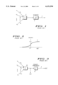
- FIG. 2 shows a non-linear transfer function in the form of a sigmoid-shaped function which is used by the prior art neuron circuit shown in FIG. 1.
- the sigmoid curve 6 is expressed by the equation:
- FIG. 3 shows another prior art neuron circuit, referred to as a perceptron neuron, which employs a binary threshold function.
- the perceptron neuron uses a binary threshold 14 as the non-linear function.
- a typical conventional neuron circuit requires circuitry for weighted input connections, a summing circuit, a multiplier circuit, and complex circuitry for performing the non-linear function.
- a summing circuit for weighted input connections
- a multiplier circuit for multiplying the weight of the input signals
- complex circuitry for performing the non-linear function.
- an artificial neuron which requires only a multiplier as its main processing element.
- the artificial neuron may be implemented either in hardware or in software.
- a neuron circuit which requires only a multiplier circuit as its main processing element. Unlike conventional neuron circuits, a neuron circuit embodying the concepts of the present invention need not utilize any non-linear function or a summing circuit. Therefore, many more neuron circuits can be integrated in a VLSI chip, which greatly increases the computational power of a neural network using one or more of such chips.
- a neural network constructed of a plurality of artificial neurons in accordance with the present invention converges on a global solution in a single training cycle (also referred to as an epoch or iteration) which can often be computed in no more than a few minutes on a personal computer.
- a neural network comprising artificial neurons in accordance with the present invention performs with vastly more accurate results, at a vastly improved reduction in computational time, and with a vast reduction in the cost and complexity of its implementation, whether on a semiconductor chip or in a computer program.
- a neuron circuit which comprises a minimum of circuit elements so that a neural network may be built comprising a very large number of such neuron circuits, resulting in a product which is commercially competitive due to its high level of functionality and low cost of manufacture.
- Yet another advantage of the present invention is to provide an artificial neuron which can be utilized as the building block of a neural network (disclosed in the above-identified Related Invention) which does not require repetitive training and which yields a global minimum to each given set of input vectors.
- a neuron circuit comprising a multiplier circuit responsive to a plurality of gated inputs and generating an output, the multiplier circuit comprising: means for multiplying the gated inputs together to produce a product; and means for multiplying the product by a predetermined weight to generate the output.
- a method of producing an output comprising (a) applying a gating function (g i ) to each of the inputs x i to produce a corresponding plurality of gated inputs; (b) multiplying the gated inputs together to produce a product; and (c) multiplying the product by a predetermined weight W.
- FIG. 1 shows a prior art neuron circuit.
- FIG. 2 shows a non-linear transfer function in the form of a sigmoid-shaped function which is used by the prior art neuron circuit shown in FIG. 1.
- FIG. 3 shows another prior art neuron circuit, referred to as a perceptron neuron, which employs a binary threshold function.
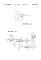
- FIG. 4 shows a conceptual block diagram of an artificial neuron in accordance with a preferred embodiment of the invention.
- FIG. 5 shows a logic circuit implementation of a neuron circuit in accordance with a preferred embodiment of the invention.
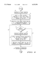
- FIG. 6 shows a flow diagram of a method of using a neuron circuit in accordance with a preferred embodiment of the invention.
- FIG. 7 shows a flow diagram of an alternative method of using an artificial neuron in accordance with the present invention.
- FIG. 8 shows a flow diagram of a gating function which may form part of the methods of using an artificial neuron illustrated in FIGS. 6 and 7.
- neuron circuit and “neuron” are used interchangeably in this description, as are the terms “multiplier circuit” or “multiplier”, and the terms “summing circuit” or “summer”, depending upon the type of implementation.
- multiplier circuit is defined herein to include a divider circuit
- multiplier is defined herein to include a divider
- FIG. 4 a conceptual block diagram of an artificial neuron in accordance with a preferred embodiment of the invention is shown.
- Inputs x 1 , x 2 , . . . , x n are gated by respective gating functions g 1 , g 2 , . . . , g n to produce gated inputs having exponential powers.
- the gated inputs x 1 g1 , x 2 g2 , . . . , x n gn are multiplied together in multiplier 22, and their product is multiplied by a weight w i shown conceptually as weight W being input over line 24.
- the resulting product represents the output (OUT) from multiplier 22 over line 25.
- g i and w i are determined by the individual terms of a polynomial expansion or orthogonal function which is utilized as the basis of operation of a neural network incorporating a plurality of the herein-described artificial neurons.
- FIG. 4 may be implemented in many different ways, one of which is shown in FIG. 5.
- FIG. 5 is a digital implementation of the neuron circuit of the present invention which is conceptually shown in FIG. 4.
- a plurality of inputs x i are sequentially applied to the neuron circuit.
- the neuron circuit comprises five primary elements: counter/latch 20, multiplier 22, multiplexer (MUX) 26, latch 28, and output latch 38.
- An input latch 18 is also shown as part of this circuit implementation; however, in a neural network comprising a plurality of neuron circuits, as disclosed, for example, in the above-identified Related Invention, a single input latch 18 may be shared by a plurality of neuron circuits.
- Multiplier 22 represents the only significant processing element of the neuron circuit.
- Input latch 18 receives inputs x i over, for example, an 8-bit data bus 16, although it will be understood by one of ordinary skill in the art that the width of the data bus may be 16 bits, floating-point, or any other desired value. Input latch 18 is controlled by an INPUT CLOCK.
- the INPUT CLOCK is incremented when the count in counter/latch 20 reaches 0. It will be understood by one of ordinary skill that a neural network comprises many neuron circuits, each of which may comprise a counter/latch circuit, and that the INPUT CLOCK will not be incremented until the count in all of such counter/latches reaches 0.
- the output of input latch 18 is fed to counter/latch 20 via an 8-bit data bus 19.
- Counter/latch 20 and latch 28 are responsive to an internal clock signal (CLK). CLK increments at a constant rate. Counter/latch 20 and latch 28 receive CLK via lines 30 and 32, respectively.
- CLK internal clock signal
- Counter/latch 20 serves to hold the input data for a desired number of CLK cycles in order to produce the desired gating function.
- Counter/latch 20 is responsive to a gating input line 34 over which are provided exponential values g i for the corresponding input values x i .
- the output of counter/latch 20 is provided to multiplier 22 via an 8-bit data bus 21.
- the output of multiplier 22 is coupled to the input of latch 28 via 8-bit data bus segments 23 and 36 and via multiplexer 26.
- Multiplexer 26 multiplexes the output values of multiplier 22, received over bus segment 36, and weight W, received over line 24, to the input of latch 28.
- the output of multiplier 22 is also coupled to the input of output latch 38 via 8-bit data bus segment 35.
- Weight W is also coupled to an input of output latch 38 via an 8-bit bus segment 37. For certain calculations it will be understood that W can be sent to output latch 38 directly, bypassing the multiplier 22.
- MUX 26 is switched to line 24 to receive weight W. After multiplier circuit 22 generates the first product, MIX 26 switches to couple line 36 to latch 28.
- Latch 28 temporarily holds the output of multiplier 22 for multiplying by the output of counter/latch 20.
- FIG. 6 shows a flow diagram of a method of using a neuron circuit in accordance with a preferred embodiment of the invention. The method whose steps are illustrated in FIG. 6 relates to the neuron circuit shown in FIG. 5.
- a first input is received by the neuron circuit, e.g. by latch 18 (FIG. 5).
- a first gating function is applied to the first input to produce a first gated input.
- the gating function is shown in greater detail in FIG. 8, discussed below.
- the first gated input is multiplied by a predetermined weight W to produce a product.
- decision box 44 a check is made to determine whether all inputs have yet been received. If so, the procedure is finished with the current batch of inputs, and it exits via line 45. If not, the procedure proceeds to box 46.
- box 48 the gated input produced in box 47 is multiplied by the product produced in box 43 (or previously produced in box 48, if this is not the first time through box 48) to produce a product.
- FIG. 7 shows a flow diagram of an alternative method of using an artificial neuron in accordance with the present invention.
- the method whose steps are illustrated in FIG. 7 relates to the artificial neuron shown in FIG. 4.
- a plurality of inputs x i are received by the artificial neuron and distributed to the multiplier circuit.
- a gating function is applied to each of them to produce a corresponding plurality of gated inputs.
- the gating function is shown in greater detail in FIG. 8, discussed below.
- the gated inputs are multiplied together to produce a product.
- the product is multiplied by a predetermined weight W to produce a product representing the output of the artificial neuron.
- FIG. 8 shows a flow diagram of a gating function which may form part of the methods of using an artificial neuron illustrated in FIGS. 6 and 7.
- the gating function applicable to the inputs x i of the neuron circuit may be expressed by the following: (a) if the gating function g i is 0, pass 1 to the multiplier circuit 22 (refer to box 60 of FIG. 8); (b) if the gating function g i is 1, pass the input x i to the multiplier circuit 22 (refer to box 62 ); and if the gating function is greater than 1, pass the input x i raised to the g i power to the multiplier circuit 22 (refer to box 64 ).
- the neuron circuit of the embodiment shown in FIG. 4 thus generates an output of the form W x 1 g 1 x 2 g 2 . . . x n g n.
- the object is to generate a neuron circuit output of 6 x 1 3 x 2 2 for any value of input variables x 1 and x 2 .
- counter/latch 20 begins counting down, and, so long as the g i count is not equal to 0, x 1 will continually be multiplied by the product of the multiplier 22.
- multiplier 22 will cease multiplication (or will simply continue multiplying the product by 1, depending upon the implementation of a neural network incorporating the neuron circuit) and wait for the next input x 2 .
- the intermediate output of the neuron circuit is 6 x 1 3 .
- weight of the neuron circuit was multiplied at the beginning of the computational cycle, it will be understood that it may be multiplied at any appropriate time.
- the various embodiments of neural networks which use the herein-disclosed artificial neuron as a basic building block. This is because of the unique functions of such artificial neuron, namely the ability to multiply together a plurality of gated inputs and to multiply the resulting product by a weight value. Because of these properties, the various embodiments of neural networks which are disclosed in the above-identified Related Invention may use the herein-disclosed artificial neuron to great advantage in implementing the polynomial expansions or orthogonal functions which form the basis of operation of such neural networks.
- an artificial neuron that can form the basis of a neural network which does not require lengthy training cycles and which converges on a global solution in a single training cycle.
- neuron circuit of the present invention could be implemented in analog technology or by a combination of analog and digital technologies.
- implementations may be made in which the plurality of inputs x i may be processed in parallel rather than sequentially by appropriate circuitry.
- the output latch may be replaced by a multiplexer.
Abstract
Description
OUTPUT=1/(1+e.sup.-NET) EQUATION 1
              TABLE I
______________________________________
INPUT
  CLOCK CLK
  SEQUENCE SEQUENCE COUNTER/LATCH OUTPUT
______________________________________
1        1          3             6 x.sub.1
  1 2 2 6 x.sub.1.sup.2
  1 3 1 6 x.sub.1.sup.3
  1 4 0 6 x.sub.1.sup.3
  2 5 2 6 x.sub.1.sup.3 x.sub.2
  2 6 1 6 x.sub.1.sup.3 x.sub.2.sup.2
  2 7 0 6 x.sub.1.sup.3 x.sub.2.sup.2
  2 8 -- 6 x.sub.1.sup.3 x.sub.2.sup.2
______________________________________
Claims (8)
Priority Applications (1)
| Application Number | Priority Date | Filing Date | Title |
|---|---|---|---|
| US08/294,235 US6151594A (en) | 1993-06-14 | 1994-08-22 | Artificial neuron and method of using same |
Applications Claiming Priority (2)
| Application Number | Priority Date | Filing Date | Title |
|---|---|---|---|
| US08/076,602 US5390136A (en) | 1993-06-14 | 1993-06-14 | Artificial neuron and method of using same |
| US08/294,235 US6151594A (en) | 1993-06-14 | 1994-08-22 | Artificial neuron and method of using same |
Related Parent Applications (1)
| Application Number | Title | Priority Date | Filing Date |
|---|---|---|---|
| US08/076,602 Continuation US5390136A (en) | 1993-06-14 | 1993-06-14 | Artificial neuron and method of using same |
Publications (1)
| Publication Number | Publication Date |
|---|---|
| US6151594A true US6151594A (en) | 2000-11-21 |
Family
ID=22133071
Family Applications (2)
| Application Number | Title | Priority Date | Filing Date |
|---|---|---|---|
| US08/076,602 Expired - Fee Related US5390136A (en) | 1993-06-14 | 1993-06-14 | Artificial neuron and method of using same |
| US08/294,235 Expired - Lifetime US6151594A (en) | 1993-06-14 | 1994-08-22 | Artificial neuron and method of using same |
Family Applications Before (1)
| Application Number | Title | Priority Date | Filing Date |
|---|---|---|---|
| US08/076,602 Expired - Fee Related US5390136A (en) | 1993-06-14 | 1993-06-14 | Artificial neuron and method of using same |
Country Status (8)
| Country | Link |
|---|---|
| US (2) | US5390136A (en) |
| EP (1) | EP0629969A1 (en) |
| JP (1) | JPH0713950A (en) |
| KR (1) | KR950001520A (en) |
| CN (1) | CN1107598A (en) |
| CA (1) | CA2125244A1 (en) |
| MX (1) | MX9404367A (en) |
| TW (1) | TW240304B (en) |
Cited By (7)
| Publication number | Priority date | Publication date | Assignee | Title |
|---|---|---|---|---|
| US6374385B1 (en) * | 1998-05-26 | 2002-04-16 | Nokia Mobile Phones Limited | Method and arrangement for implementing convolutional decoding |
| US6501294B2 (en) * | 2001-04-26 | 2002-12-31 | International Business Machines Corporation | Neuron circuit |
| US20040015459A1 (en) * | 2000-10-13 | 2004-01-22 | Herbert Jaeger | Method for supervised teaching of a recurrent artificial neural network |
| US20060004681A1 (en) * | 2004-04-29 | 2006-01-05 | Michel Howard E | Artificial neuron with phase-encoded logic |
| US20070011112A1 (en) * | 1997-02-14 | 2007-01-11 | Nikon Corporation | Method of determining movement sequence, alignment apparatus, method and apparatus of designing optical system, and medium in which program realizing the designing method |
| US10606960B2 (en) | 2001-10-11 | 2020-03-31 | Ebay Inc. | System and method to facilitate translation of communications between entities over a network |
| US11445037B2 (en) | 2006-08-23 | 2022-09-13 | Ebay, Inc. | Dynamic configuration of multi-platform applications |
Families Citing this family (34)
| Publication number | Priority date | Publication date | Assignee | Title |
|---|---|---|---|---|
| US6324453B1 (en) | 1998-12-31 | 2001-11-27 | Automotive Technologies International, Inc. | Methods for determining the identification and position of and monitoring objects in a vehicle |
| US6553296B2 (en) | 1995-06-07 | 2003-04-22 | Automotive Technologies International, Inc. | Vehicular occupant detection arrangements |
| US6393133B1 (en) | 1992-05-05 | 2002-05-21 | Automotive Technologies International, Inc. | Method and system for controlling a vehicular system based on occupancy of the vehicle |
| US6507779B2 (en) | 1995-06-07 | 2003-01-14 | Automotive Technologies International, Inc. | Vehicle rear seat monitor |
| US6772057B2 (en) | 1995-06-07 | 2004-08-03 | Automotive Technologies International, Inc. | Vehicular monitoring systems using image processing |
| US6856873B2 (en) | 1995-06-07 | 2005-02-15 | Automotive Technologies International, Inc. | Vehicular monitoring systems using image processing |
| US6442465B2 (en) | 1992-05-05 | 2002-08-27 | Automotive Technologies International, Inc. | Vehicular component control systems and methods |
| US5845000A (en) * | 1992-05-05 | 1998-12-01 | Automotive Technologies International, Inc. | Optical identification and monitoring system using pattern recognition for use with vehicles |
| US6517107B2 (en) | 1998-06-09 | 2003-02-11 | Automotive Technologies International, Inc. | Methods for controlling a system in a vehicle using a transmitting/receiving transducer and/or while compensating for thermal gradients |
| US6397136B1 (en) | 1997-02-06 | 2002-05-28 | Automotive Technologies International Inc. | System for determining the occupancy state of a seat in a vehicle |
| US5835613A (en) * | 1992-05-05 | 1998-11-10 | Automotive Technologies International, Inc. | Optical identification and monitoring system using pattern recognition for use with vehicles |
| US6445988B1 (en) | 1997-02-06 | 2002-09-03 | Automotive Technologies International Inc. | System for determining the occupancy state of a seat in a vehicle and controlling a component based thereon |
| US5943295A (en) | 1997-02-06 | 1999-08-24 | Automotive Technologies International Inc. | Method for identifying the presence and orientation of an object in a vehicle |
| US7788008B2 (en) * | 1995-06-07 | 2010-08-31 | Automotive Technologies International, Inc. | Eye monitoring system and method for vehicular occupants |
| US6279946B1 (en) | 1998-06-09 | 2001-08-28 | Automotive Technologies International Inc. | Methods for controlling a system in a vehicle using a transmitting/receiving transducer and/or while compensating for thermal gradients |
| WO1996035180A1 (en) * | 1995-05-05 | 1996-11-07 | Motorola Inc. | Method and system for demodulation of multi-level pcm |
| US5724486A (en) * | 1995-08-21 | 1998-03-03 | Motorola Inc. | Method for structuring an expert system utilizing one or more polynomial processors |
| US5640336A (en) * | 1996-01-02 | 1997-06-17 | Motorola | Computational array and method for calculating multiple terms of a polynomial in a single computing element |
| US6452870B1 (en) | 1996-02-08 | 2002-09-17 | Automotive Technologies International, Inc. | Methods for controlling deployment of an occupant restraint in a vehicle and determining whether the occupant is a child seat |
| USRE37260E1 (en) * | 1996-02-08 | 2001-07-03 | Automotive Technologies International Inc. | Method for identifying the presence and orientation of an object in a vehicle |
| US5864807A (en) * | 1997-02-25 | 1999-01-26 | Motorola, Inc. | Method and apparatus for training a speaker recognition system |
| US5946653A (en) * | 1997-10-01 | 1999-08-31 | Motorola, Inc. | Speaker independent speech recognition system and method |
| US6203079B1 (en) | 1997-11-24 | 2001-03-20 | Automotive Technologies International, Inc. | Damped crash attenuator |
| US6523872B2 (en) | 1997-11-24 | 2003-02-25 | Automotive Technologies International, Inc. | Damped crash attenuator |
| US6343821B2 (en) | 1997-11-24 | 2002-02-05 | Automotive Technologies International, Inc. | Damped crash attenuator |
| US6192353B1 (en) | 1998-02-09 | 2001-02-20 | Motorola, Inc. | Multiresolutional classifier with training system and method |
| US6243695B1 (en) | 1998-03-18 | 2001-06-05 | Motorola, Inc. | Access control system and method therefor |
| US6131089A (en) * | 1998-05-04 | 2000-10-10 | Motorola, Inc. | Pattern classifier with training system and methods of operation therefor |
| US6240282B1 (en) | 1998-07-13 | 2001-05-29 | Motorola, Inc. | Apparatus for performing non-linear signal classification in a communications system |
| RU2604331C2 (en) * | 2014-11-05 | 2016-12-10 | Айыысхан Иванович Алексеев | Artificial neuron (versions) |
| CN107480780A (en) * | 2017-09-03 | 2017-12-15 | 胡明建 | A kind of more threshold values polygamma functions select the design method of output artificial neuron more |
| CN107491810A (en) * | 2017-09-23 | 2017-12-19 | 胡明建 | A kind of design method of more threshold values feedback artificial neurons |
| CN107633300A (en) * | 2017-09-28 | 2018-01-26 | 胡明建 | A kind of design method of graded potential formula artificial neuron |
| CN107657315A (en) * | 2017-09-30 | 2018-02-02 | 胡明建 | A kind of graded potential formula selects the design method of end output artificial neuron |
Citations (21)
| Publication number | Priority date | Publication date | Assignee | Title |
|---|---|---|---|---|
| US3922536A (en) * | 1974-05-31 | 1975-11-25 | Rca Corp | Multionomial processor system |
| US3967100A (en) * | 1973-11-12 | 1976-06-29 | Naonobu Shimomura | Digital function generator utilizing cascade accumulation |
| US4156922A (en) * | 1977-02-01 | 1979-05-29 | Instytut Maszyn Matematyeznych | Digital system for computation of the values of composite arithmetic expressions |
| WO1987007053A1 (en) * | 1986-05-07 | 1987-11-19 | Gec Avionics Limited | Accumulating recursive computation |
| US4912649A (en) * | 1988-12-14 | 1990-03-27 | Gte Government Systems Corporation | Accelerating learning in neural networks |
| US4949292A (en) * | 1987-05-14 | 1990-08-14 | Fujitsu Limited | Vector processor for processing recurrent equations at a high speed |
| US5042001A (en) * | 1989-10-02 | 1991-08-20 | Cyrix Corporation | Method and apparatus for performing mathematical functions using polynomial approximation and a rectangular aspect ratio multiplier |
| US5073867A (en) * | 1989-06-12 | 1991-12-17 | Westinghouse Electric Corp. | Digital neural network processing elements |
| US5170071A (en) * | 1991-06-17 | 1992-12-08 | Trw Inc. | Stochastic artifical neuron with multilayer training capability |
| US5179631A (en) * | 1990-09-27 | 1993-01-12 | Board Of Supervisors Of Louisiana State University And Agricultural And Mechanical College | Neural network logic system |
| US5191637A (en) * | 1989-07-12 | 1993-03-02 | Ricoh Company, Ltd. | Neuron unit and neuron unit network |
| US5220559A (en) * | 1988-08-31 | 1993-06-15 | Fujitsu Limited | Neuron architecture |
| US5239594A (en) * | 1991-02-12 | 1993-08-24 | Mitsubishi Denki Kabushiki Kaisha | Self-organizing pattern classification neural network system |
| US5271090A (en) * | 1990-03-21 | 1993-12-14 | At&T Bell Laboratories | Operational speed improvement for neural network |
| US5278945A (en) * | 1992-01-10 | 1994-01-11 | American Neuralogical, Inc. | Neural processor apparatus |
| US5323470A (en) * | 1992-05-08 | 1994-06-21 | Atsushi Kara | Method and apparatus for automatically tracking an object |
| US5355436A (en) * | 1992-10-05 | 1994-10-11 | The Research Foundation, State University Of New York At Buffalo | Single layer neural network circuit for performing linearly separable and non-linearly separable logical operations |
| US5386497A (en) * | 1992-08-18 | 1995-01-31 | Torrey; Stephen A. | Electronic neuron simulation with more accurate functions |
| US5394511A (en) * | 1989-12-26 | 1995-02-28 | Mitsubishi Denki Kabushiki Kaisha | Coupling element for semiconductor neural network device |
| US5408588A (en) * | 1991-06-06 | 1995-04-18 | Ulug; Mehmet E. | Artificial neural network method and architecture |
| US5412565A (en) * | 1991-12-27 | 1995-05-02 | At&T Corp. | Electronic synapse circuit for artificial neural network |
Family Cites Families (2)
| Publication number | Priority date | Publication date | Assignee | Title |
|---|---|---|---|---|
| EP0218971A3 (en) * | 1985-09-30 | 1990-04-11 | Siemens Aktiengesellschaft | Method for solving equations of the type z = ((x1**y1) op (x2**y2) op ... op (xn**ym))**(1/k) |
| JP3102918B2 (en) * | 1990-11-22 | 2000-10-23 | 株式会社リコー | Neural network learning method and signal processing device using this learning method |
-
1993
- 1993-06-14 US US08/076,602 patent/US5390136A/en not_active Expired - Fee Related
-
1994
- 1994-05-10 TW TW083104209A patent/TW240304B/zh active
- 1994-06-06 CA CA002125244A patent/CA2125244A1/en not_active Abandoned
- 1994-06-09 MX MX9404367A patent/MX9404367A/en not_active IP Right Cessation
- 1994-06-09 JP JP6151654A patent/JPH0713950A/en active Pending
- 1994-06-10 KR KR1019940013277A patent/KR950001520A/en not_active Application Discontinuation
- 1994-06-10 CN CN94106565A patent/CN1107598A/en active Pending
- 1994-06-13 EP EP94304233A patent/EP0629969A1/en not_active Withdrawn
- 1994-08-22 US US08/294,235 patent/US6151594A/en not_active Expired - Lifetime
Patent Citations (21)
| Publication number | Priority date | Publication date | Assignee | Title |
|---|---|---|---|---|
| US3967100A (en) * | 1973-11-12 | 1976-06-29 | Naonobu Shimomura | Digital function generator utilizing cascade accumulation |
| US3922536A (en) * | 1974-05-31 | 1975-11-25 | Rca Corp | Multionomial processor system |
| US4156922A (en) * | 1977-02-01 | 1979-05-29 | Instytut Maszyn Matematyeznych | Digital system for computation of the values of composite arithmetic expressions |
| WO1987007053A1 (en) * | 1986-05-07 | 1987-11-19 | Gec Avionics Limited | Accumulating recursive computation |
| US4949292A (en) * | 1987-05-14 | 1990-08-14 | Fujitsu Limited | Vector processor for processing recurrent equations at a high speed |
| US5220559A (en) * | 1988-08-31 | 1993-06-15 | Fujitsu Limited | Neuron architecture |
| US4912649A (en) * | 1988-12-14 | 1990-03-27 | Gte Government Systems Corporation | Accelerating learning in neural networks |
| US5073867A (en) * | 1989-06-12 | 1991-12-17 | Westinghouse Electric Corp. | Digital neural network processing elements |
| US5191637A (en) * | 1989-07-12 | 1993-03-02 | Ricoh Company, Ltd. | Neuron unit and neuron unit network |
| US5042001A (en) * | 1989-10-02 | 1991-08-20 | Cyrix Corporation | Method and apparatus for performing mathematical functions using polynomial approximation and a rectangular aspect ratio multiplier |
| US5394511A (en) * | 1989-12-26 | 1995-02-28 | Mitsubishi Denki Kabushiki Kaisha | Coupling element for semiconductor neural network device |
| US5271090A (en) * | 1990-03-21 | 1993-12-14 | At&T Bell Laboratories | Operational speed improvement for neural network |
| US5179631A (en) * | 1990-09-27 | 1993-01-12 | Board Of Supervisors Of Louisiana State University And Agricultural And Mechanical College | Neural network logic system |
| US5239594A (en) * | 1991-02-12 | 1993-08-24 | Mitsubishi Denki Kabushiki Kaisha | Self-organizing pattern classification neural network system |
| US5408588A (en) * | 1991-06-06 | 1995-04-18 | Ulug; Mehmet E. | Artificial neural network method and architecture |
| US5170071A (en) * | 1991-06-17 | 1992-12-08 | Trw Inc. | Stochastic artifical neuron with multilayer training capability |
| US5412565A (en) * | 1991-12-27 | 1995-05-02 | At&T Corp. | Electronic synapse circuit for artificial neural network |
| US5278945A (en) * | 1992-01-10 | 1994-01-11 | American Neuralogical, Inc. | Neural processor apparatus |
| US5323470A (en) * | 1992-05-08 | 1994-06-21 | Atsushi Kara | Method and apparatus for automatically tracking an object |
| US5386497A (en) * | 1992-08-18 | 1995-01-31 | Torrey; Stephen A. | Electronic neuron simulation with more accurate functions |
| US5355436A (en) * | 1992-10-05 | 1994-10-11 | The Research Foundation, State University Of New York At Buffalo | Single layer neural network circuit for performing linearly separable and non-linearly separable logical operations |
Non-Patent Citations (33)
| Title |
|---|
| A Digital Neuron Type Processor and Its VLSI Design, Mahmoud K. Habib et al., IEEE Transactions on Circuits and Systems 36 (1989) May, No. 5, New York, pp. 739 746. * |
| A Digital Neuron-Type Processor and Its VLSI Design, Mahmoud K. Habib et al., IEEE Transactions on Circuits and Systems 36 (1989) May, No. 5, New York, pp. 739-746. |
| A Neural Feed Forward Network with a Polynomial Nonlinearity, Nils Hoffmann, Electronics Institute, Building 349, Technical University of Denmark, DK 2800 Lyngby, Denmark, Neural Networks for Signal Processing, Proceedings of the IEEE SP Workshop, Aug. 31 Sep.2, 1992, pp. 49 58. * |
| A Neural Feed-Forward Network with a Polynomial Nonlinearity, Nils Hoffmann, Electronics Institute, Building 349, Technical University of Denmark, DK-2800 Lyngby, Denmark, Neural Networks for Signal Processing, Proceedings of the IEEE-SP Workshop, Aug. 31-Sep.2, 1992, pp. 49-58. |
| A Polynomial Time Algorithm for Generating Neural Networks for Classification Problems, Asim Roy et al., IJCNN, 1992, pp. I 147 I 152. * |
| A Polynomial Time Algorithm for Generating Neural Networks for Classification Problems, Asim Roy et al., IJCNN, 1992, pp. I-147-I-152. |
| AIM Outperforms Neural Networks and Regression, Mark Shewhart, USAF (IEEE Spectrum), AbTech Corporation, Charlotteville, VA 22903. * |
| An Artificial Neural Networks for Approximating Polynomial Functions, Behnam Malakooti and YingQing Zhou, Department of Systems Engineering, Center for Automation and Intelligent Systems Research, Case Western Reserve University, Cleveland, Ohio, International Joint Conference on Neural Networks, Jun. 1992, pp. III 966 III 971. * |
| An Artificial Neural Networks for Approximating Polynomial Functions, Behnam Malakooti and YingQing Zhou, Department of Systems Engineering, Center for Automation and Intelligent Systems Research, Case Western Reserve University, Cleveland, Ohio, International Joint Conference on Neural Networks, Jun. 1992, pp. III-966-III-971. |
| Backpropagation Based on the Logarithmic Error Function and Elimination of Local Minima, Kiyotoshi Matsuoka and Jianqiang Yi, Department of Control Engineering, Kyushu Institute of Technology, Sensul 1 1. Tobata. Kitakyushu, 804 Japan, CH3065 0/91/0000 1117 IEEE, pp. 1117 1122. * |
| Backpropagation Based on the Logarithmic Error Function and Elimination of Local Minima, Kiyotoshi Matsuoka and Jianqiang Yi, Department of Control Engineering, Kyushu Institute of Technology, Sensul 1-1. Tobata. Kitakyushu, 804 Japan, CH3065-0/91/0000-1117 IEEE, pp. 1117-1122. |
| Generalization and Learning in Volterra and Radial Basis Function Networks: A Theoretical Analysis, Sean B. Holden and Peter J.W. Rayner, Cambridge University Engineering Department,Trumpington Street, Cambridge CB2 1PZ, U.K., 0 7803 0532 9/92, 1992 IEEE, pp. II 273 II 276. * |
| Generalization and Learning in Volterra and Radial Basis Function Networks: A Theoretical Analysis, Sean B. Holden and Peter J.W. Rayner, Cambridge University Engineering Department,Trumpington Street, Cambridge CB2 1PZ, U.K., 0-7803-0532-9/92, 1992 IEEE, pp. II-273-II-276. |
| Hata et al, "Gate Model Networks for Minimization of Multiple-Valued Logic Functions", Proceedings of the Twenty-Third Inter-Symposium on Multiple-Valued Logic, IEEE, May 24-27, 1993. |
| Hata et al, Gate Model Networks for Minimization of Multiple Valued Logic Functions , Proceedings of the Twenty Third Inter Symposium on Multiple Valued Logic, IEEE, May 24 27, 1993. * |
| Highly automated, Non parametric statistical learning for autonomous target recognition, Keith C. Drake, AbTech Corporation, 700 Harris Street, Charlottesville, Virginia 22903, pp. 1 10, Proceedings of the SPI 20th Applied Imagery Pattern Recognition Workshop, Oct. 1991, McLean, Virginia. * |
| Highly-automated, Non-parametric statistical learning for autonomous target recognition, Keith C. Drake, AbTech Corporation, 700 Harris Street, Charlottesville, Virginia 22903, pp. 1-10, Proceedings of the SPI 20th Applied Imagery Pattern Recognition Workshop, Oct. 1991, McLean, Virginia. |
| Modeling systems with Polynomial Networks, Tools for Predicting Behavior, Peter D. Varhol, Programmer s Workbench, Dr. Dobb s Journal, Sep. 1993, Begins on p. 76. * |
| Modeling systems with Polynomial Networks, Tools for Predicting Behavior, Peter D. Varhol, Programmer's Workbench, Dr. Dobb's Journal, Sep. 1993, Begins on p. 76. |
| On the Design Principles of the Functional Link Nets, Jun Wang and Edilberto P. Teixeira, Department of Systems Engineering, Case Western Reserve University, Cleveland, Ohio 44106, pp. 613 616, Ieee Internation Conf. on Systems Engineering, Aug. 9 11, 1990, Vista International Hotel, Pittsburgh, Pennsylvania, IEEE Catalog No.:90CH2872 0. * |
| On the Design Principles of the Functional Link Nets, Jun Wang and Edilberto P. Teixeira, Department of Systems Engineering, Case Western Reserve University, Cleveland, Ohio 44106, pp. 613-616, Ieee Internation Conf. on Systems Engineering, Aug. 9-11, 1990, Vista International Hotel, Pittsburgh, Pennsylvania, IEEE Catalog No.:90CH2872-0. |
| Output Weight Optimization for the Multi Layer Perception, M.T. Manry et al., Twenty sixth Asilomar Conference on Signals, Systems and Computers, Oct. 1992, pp. 26 28. * |
| Output Weight Optimization for the Multi-Layer Perception, M.T. Manry et al., Twenty-sixth Asilomar Conference on Signals, Systems and Computers, Oct. 1992, pp. 26-28. |
| Polynomial and Standard Higher Order Neural Network, Chir Ho Chang, Jin Ling Lin, and J.Y. Cheung, Electrical Engineering and Computer Science, University of Oklahoma, 1993 IEEE International Conference on Neural Networks, Mar. 28 April 1, 1993, pp. 989 994. * |
| Polynomial and Standard Higher Order Neural Network, Chir-Ho Chang, Jin-Ling Lin, and J.Y. Cheung, Electrical Engineering and Computer Science, University of Oklahoma, 1993 IEEE International Conference on Neural Networks, Mar. 28-April 1, 1993, pp. 989-994. |
| Polynomial Functions Can Be Realized by Finite Size Multilayer Feedforward Neural Networks, Naohiro Toda, Ken ichi Funahashi and Shiro Usui Department of Information and Computer Sciences, Toyohashi University of Technology, Tempaku, Toyohashi 441, Japan, 1991 IEEE International Joint Conference on Neural Networks, vol. 1of3, The Westin Stamford and Westin Plaza, Nov. 18 21, 1991, Singapore. * |
| Polynomial Functions Can Be Realized by Finite Size Multilayer Feedforward Neural Networks, Naohiro Toda, Ken-ichi Funahashi and Shiro Usui Department of Information and Computer Sciences, Toyohashi University of Technology, Tempaku, Toyohashi 441, Japan, 1991 IEEE International Joint Conference on Neural Networks, vol. 1of3, The Westin Stamford and Westin Plaza, Nov. 18-21, 1991, Singapore. |
| Recursive Reduction in Finite Ring Computations, D. Zhang, G.A. Jullien, W.C. Miller, VLSI Research Group, Department of Electrical Engineering, University of Windsor, Windsor, Ontario Cananda N9B 3P4, Twenty Third Asilomar conf. on Signals, systems and Computers, Conference Record vol. 2of2, pp. 854 857. * |
| Recursive Reduction in Finite Ring Computations, D. Zhang, G.A. Jullien, W.C. Miller, VLSI Research Group, Department of Electrical Engineering, University of Windsor, Windsor, Ontario Cananda N9B 3P4, Twenty-Third Asilomar conf. on Signals, systems and Computers, Conference Record vol. 2of2, pp. 854-857. |
| Robot Kinematics Learning Computations Using Polynomial Neural Networks, C.L. Philip Chen and A.D. McAulay, Department of Computer Science and Engineering, Wright State University, Dayton, OH 45435, Proceedings of the 1991 IEEE, International Cof. on Robotics and Automation, Sacramento, CA, Apr. 1991, pp. 2638 2643. * |
| Robot Kinematics Learning Computations Using Polynomial Neural Networks, C.L. Philip Chen and A.D. McAulay, Department of Computer Science and Engineering, Wright State University, Dayton, OH 45435, Proceedings of the 1991 IEEE, International Cof. on Robotics and Automation, Sacramento, CA, Apr. 1991, pp. 2638-2643. |
| Training Product Unit Neural Networks with Genetic Algorithms, David J. Janson et al., IEEE Export, Oct. 1993, pp. 26 32. * |
| Training Product Unit Neural Networks with Genetic Algorithms, David J. Janson et al., IEEE Export, Oct. 1993, pp. 26-32. |
Cited By (9)
| Publication number | Priority date | Publication date | Assignee | Title |
|---|---|---|---|---|
| US20070011112A1 (en) * | 1997-02-14 | 2007-01-11 | Nikon Corporation | Method of determining movement sequence, alignment apparatus, method and apparatus of designing optical system, and medium in which program realizing the designing method |
| US6374385B1 (en) * | 1998-05-26 | 2002-04-16 | Nokia Mobile Phones Limited | Method and arrangement for implementing convolutional decoding |
| US20040015459A1 (en) * | 2000-10-13 | 2004-01-22 | Herbert Jaeger | Method for supervised teaching of a recurrent artificial neural network |
| US7321882B2 (en) * | 2000-10-13 | 2008-01-22 | Fraunhofer-Gesellschaft Zur Foederung Der Angewandten Forschung E.V. | Method for supervised teaching of a recurrent artificial neural network |
| US6501294B2 (en) * | 2001-04-26 | 2002-12-31 | International Business Machines Corporation | Neuron circuit |
| US10606960B2 (en) | 2001-10-11 | 2020-03-31 | Ebay Inc. | System and method to facilitate translation of communications between entities over a network |
| US20060004681A1 (en) * | 2004-04-29 | 2006-01-05 | Michel Howard E | Artificial neuron with phase-encoded logic |
| US7401058B2 (en) | 2004-04-29 | 2008-07-15 | University Of Massachusetts | Artificial neuron with phase-encoded logic |
| US11445037B2 (en) | 2006-08-23 | 2022-09-13 | Ebay, Inc. | Dynamic configuration of multi-platform applications |
Also Published As
| Publication number | Publication date |
|---|---|
| MX9404367A (en) | 1995-01-31 |
| KR950001520A (en) | 1995-01-03 |
| JPH0713950A (en) | 1995-01-17 |
| EP0629969A1 (en) | 1994-12-21 |
| CA2125244A1 (en) | 1994-12-15 |
| CN1107598A (en) | 1995-08-30 |
| US5390136A (en) | 1995-02-14 |
| TW240304B (en) | 1995-02-11 |
Similar Documents
| Publication | Publication Date | Title |
|---|---|---|
| US6151594A (en) | Artificial neuron and method of using same | |
| US5781701A (en) | Neural network and method of using same | |
| US5095457A (en) | Digital multiplier employing CMOS transistors | |
| US4972363A (en) | Neural network using stochastic processing | |
| Lee et al. | Bit-sliced median filter design based on majority gate | |
| US4128890A (en) | Integrated arithmetic unit and digital networks using the unit | |
| US5671337A (en) | Neuron unit | |
| CN112698811A (en) | Neural network random number generator sharing circuit, sharing method and processor chip | |
| US5581661A (en) | Artificial neuron using adder circuit and method of using same | |
| US5778153A (en) | Neural network utilizing logarithmic function and method of using same | |
| US5384896A (en) | Learning machine | |
| US5548685A (en) | Artificial neuron using adder circuit and method of using same | |
| US5347613A (en) | MOS multi-layer neural network including a plurality of hidden layers interposed between synapse groups for performing pattern recognition | |
| US20020143720A1 (en) | Data structure for improved software implementation of a neural network | |
| US5293458A (en) | MOS Multi-layer neural network and its design method | |
| JPH076146A (en) | Parallel data processing system | |
| GB2236608A (en) | Digital neural networks | |
| Lu et al. | A parallel and modular multi-sieving neural network architecture for constructive learning | |
| Lee et al. | VLSI image processor using analog programmable synapses and neurons | |
| Lenze | Improving Leung's bidirectional learning rule for associative memories | |
| US5958001A (en) | Output-processing circuit for a neural network and method of using same | |
| CN113065648B (en) | Hardware implementation method of piecewise linear function with low hardware cost | |
| Chen et al. | Design and VLSI implementation of real-time weighted median filters | |
| Aihara et al. | A digital neural network LSI using sparse memory access architecture | |
| Ghorbani et al. | Training artificial neural networks using variable precision incremental communication |
Legal Events
| Date | Code | Title | Description |
|---|---|---|---|
| STCF | Information on status: patent grant |
Free format text: PATENTED CASE |
|
| FPAY | Fee payment |
Year of fee payment: 4 |
|
| AS | Assignment |
Owner name: FREESCALE SEMICONDUCTOR, INC., TEXAS Free format text: ASSIGNMENT OF ASSIGNORS INTEREST;ASSIGNOR:MOTOROLA, INC.;REEL/FRAME:015698/0657 Effective date: 20040404 Owner name: FREESCALE SEMICONDUCTOR, INC.,TEXAS Free format text: ASSIGNMENT OF ASSIGNORS INTEREST;ASSIGNOR:MOTOROLA, INC.;REEL/FRAME:015698/0657 Effective date: 20040404 |
|
| AS | Assignment |
Owner name: CITIBANK, N.A. AS COLLATERAL AGENT, NEW YORK Free format text: SECURITY AGREEMENT;ASSIGNORS:FREESCALE SEMICONDUCTOR, INC.;FREESCALE ACQUISITION CORPORATION;FREESCALE ACQUISITION HOLDINGS CORP.;AND OTHERS;REEL/FRAME:018855/0129 Effective date: 20061201 Owner name: CITIBANK, N.A. AS COLLATERAL AGENT,NEW YORK Free format text: SECURITY AGREEMENT;ASSIGNORS:FREESCALE SEMICONDUCTOR, INC.;FREESCALE ACQUISITION CORPORATION;FREESCALE ACQUISITION HOLDINGS CORP.;AND OTHERS;REEL/FRAME:018855/0129 Effective date: 20061201 |
|
| FPAY | Fee payment |
Year of fee payment: 8 |
|
| AS | Assignment |
Owner name: CITIBANK, N.A., AS COLLATERAL AGENT,NEW YORK Free format text: SECURITY AGREEMENT;ASSIGNOR:FREESCALE SEMICONDUCTOR, INC.;REEL/FRAME:024397/0001 Effective date: 20100413 Owner name: CITIBANK, N.A., AS COLLATERAL AGENT, NEW YORK Free format text: SECURITY AGREEMENT;ASSIGNOR:FREESCALE SEMICONDUCTOR, INC.;REEL/FRAME:024397/0001 Effective date: 20100413 |
|
| FPAY | Fee payment |
Year of fee payment: 12 |
|
| AS | Assignment |
Owner name: CITIBANK, N.A., AS NOTES COLLATERAL AGENT, NEW YOR Free format text: SECURITY AGREEMENT;ASSIGNOR:FREESCALE SEMICONDUCTOR, INC.;REEL/FRAME:030633/0424 Effective date: 20130521 |
|
| AS | Assignment |
Owner name: CITIBANK, N.A., AS NOTES COLLATERAL AGENT, NEW YOR Free format text: SECURITY AGREEMENT;ASSIGNOR:FREESCALE SEMICONDUCTOR, INC.;REEL/FRAME:031591/0266 Effective date: 20131101 |
|
| AS | Assignment |
Owner name: FREESCALE SEMICONDUCTOR, INC., TEXAS Free format text: PATENT RELEASE;ASSIGNOR:CITIBANK, N.A., AS COLLATERAL AGENT;REEL/FRAME:037354/0225 Effective date: 20151207 Owner name: FREESCALE SEMICONDUCTOR, INC., TEXAS Free format text: PATENT RELEASE;ASSIGNOR:CITIBANK, N.A., AS COLLATERAL AGENT;REEL/FRAME:037356/0553 Effective date: 20151207 Owner name: FREESCALE SEMICONDUCTOR, INC., TEXAS Free format text: PATENT RELEASE;ASSIGNOR:CITIBANK, N.A., AS COLLATERAL AGENT;REEL/FRAME:037356/0143 Effective date: 20151207 |
|
| AS | Assignment |
Owner name: MORGAN STANLEY SENIOR FUNDING, INC., MARYLAND Free format text: ASSIGNMENT AND ASSUMPTION OF SECURITY INTEREST IN PATENTS;ASSIGNOR:CITIBANK, N.A.;REEL/FRAME:037486/0517 Effective date: 20151207 |
|
| AS | Assignment |
Owner name: MORGAN STANLEY SENIOR FUNDING, INC., MARYLAND Free format text: ASSIGNMENT AND ASSUMPTION OF SECURITY INTEREST IN PATENTS;ASSIGNOR:CITIBANK, N.A.;REEL/FRAME:037518/0292 Effective date: 20151207 |
|
| AS | Assignment |
Owner name: NXP, B.V., F/K/A FREESCALE SEMICONDUCTOR, INC., NETHERLANDS Free format text: RELEASE BY SECURED PARTY;ASSIGNOR:MORGAN STANLEY SENIOR FUNDING, INC.;REEL/FRAME:040925/0001 Effective date: 20160912 Owner name: NXP, B.V., F/K/A FREESCALE SEMICONDUCTOR, INC., NE Free format text: RELEASE BY SECURED PARTY;ASSIGNOR:MORGAN STANLEY SENIOR FUNDING, INC.;REEL/FRAME:040925/0001 Effective date: 20160912 |
|
| AS | Assignment |
Owner name: NXP B.V., NETHERLANDS Free format text: RELEASE BY SECURED PARTY;ASSIGNOR:MORGAN STANLEY SENIOR FUNDING, INC.;REEL/FRAME:040928/0001 Effective date: 20160622 |
|
| AS | Assignment |
Owner name: MORGAN STANLEY SENIOR FUNDING, INC., MARYLAND Free format text: CORRECTIVE ASSIGNMENT TO CORRECT THE REMOVE PATENTS 8108266 AND 8062324 AND REPLACE THEM WITH 6108266 AND 8060324 PREVIOUSLY RECORDED ON REEL 037518 FRAME 0292. ASSIGNOR(S) HEREBY CONFIRMS THE ASSIGNMENT AND ASSUMPTION OF SECURITY INTEREST IN PATENTS;ASSIGNOR:CITIBANK, N.A.;REEL/FRAME:041703/0536 Effective date: 20151207 |
|
| AS | Assignment |
Owner name: SHENZHEN XINGUODU TECHNOLOGY CO., LTD., CHINA Free format text: CORRECTIVE ASSIGNMENT TO CORRECT THE TO CORRECT THE APPLICATION NO. FROM 13,883,290 TO 13,833,290 PREVIOUSLY RECORDED ON REEL 041703 FRAME 0536. ASSIGNOR(S) HEREBY CONFIRMS THE THE ASSIGNMENT AND ASSUMPTION OF SECURITYINTEREST IN PATENTS.;ASSIGNOR:MORGAN STANLEY SENIOR FUNDING, INC.;REEL/FRAME:048734/0001 Effective date: 20190217 |
|
| AS | Assignment |
Owner name: MORGAN STANLEY SENIOR FUNDING, INC., MARYLAND Free format text: CORRECTIVE ASSIGNMENT TO CORRECT THE REMOVE APPLICATION11759915 AND REPLACE IT WITH APPLICATION 11759935 PREVIOUSLY RECORDED ON REEL 037486 FRAME 0517. ASSIGNOR(S) HEREBY CONFIRMS THE ASSIGNMENT AND ASSUMPTION OF SECURITYINTEREST IN PATENTS;ASSIGNOR:CITIBANK, N.A.;REEL/FRAME:053547/0421 Effective date: 20151207 |
|
| AS | Assignment |
Owner name: NXP B.V., NETHERLANDS Free format text: CORRECTIVE ASSIGNMENT TO CORRECT THE REMOVEAPPLICATION 11759915 AND REPLACE IT WITH APPLICATION11759935 PREVIOUSLY RECORDED ON REEL 040928 FRAME 0001. ASSIGNOR(S) HEREBY CONFIRMS THE RELEASE OF SECURITYINTEREST;ASSIGNOR:MORGAN STANLEY SENIOR FUNDING, INC.;REEL/FRAME:052915/0001 Effective date: 20160622 |
|
| AS | Assignment |
Owner name: NXP, B.V. F/K/A FREESCALE SEMICONDUCTOR, INC., NETHERLANDS Free format text: CORRECTIVE ASSIGNMENT TO CORRECT THE REMOVEAPPLICATION 11759915 AND REPLACE IT WITH APPLICATION11759935 PREVIOUSLY RECORDED ON REEL 040925 FRAME 0001. ASSIGNOR(S) HEREBY CONFIRMS THE RELEASE OF SECURITYINTEREST;ASSIGNOR:MORGAN STANLEY SENIOR FUNDING, INC.;REEL/FRAME:052917/0001 Effective date: 20160912 |