US6151958A - Ultrasonic fraction and flow rate apparatus and method - Google Patents
Ultrasonic fraction and flow rate apparatus and method Download PDFInfo
- Publication number
- US6151958A US6151958A US08/613,478 US61347896A US6151958A US 6151958 A US6151958 A US 6151958A US 61347896 A US61347896 A US 61347896A US 6151958 A US6151958 A US 6151958A
- Authority
- US
- United States
- Prior art keywords
- gas
- volume
- variations
- ultrasonic energy
- determining
- Prior art date
- Legal status (The legal status is an assumption and is not a legal conclusion. Google has not performed a legal analysis and makes no representation as to the accuracy of the status listed.)
- Expired - Lifetime
Links
Images


Classifications
-
- G—PHYSICS
- G01—MEASURING; TESTING
- G01N—INVESTIGATING OR ANALYSING MATERIALS BY DETERMINING THEIR CHEMICAL OR PHYSICAL PROPERTIES
- G01N29/00—Investigating or analysing materials by the use of ultrasonic, sonic or infrasonic waves; Visualisation of the interior of objects by transmitting ultrasonic or sonic waves through the object
- G01N29/02—Analysing fluids
- G01N29/032—Analysing fluids by measuring attenuation of acoustic waves
-
- G—PHYSICS
- G01—MEASURING; TESTING
- G01N—INVESTIGATING OR ANALYSING MATERIALS BY DETERMINING THEIR CHEMICAL OR PHYSICAL PROPERTIES
- G01N2291/00—Indexing codes associated with group G01N29/00
- G01N2291/01—Indexing codes associated with the measuring variable
- G01N2291/011—Velocity or travel time
-
- G—PHYSICS
- G01—MEASURING; TESTING
- G01N—INVESTIGATING OR ANALYSING MATERIALS BY DETERMINING THEIR CHEMICAL OR PHYSICAL PROPERTIES
- G01N2291/00—Indexing codes associated with group G01N29/00
- G01N2291/02—Indexing codes associated with the analysed material
- G01N2291/024—Mixtures
- G01N2291/02425—Liquids in gases, e.g. sprays
-
- G—PHYSICS
- G01—MEASURING; TESTING
- G01N—INVESTIGATING OR ANALYSING MATERIALS BY DETERMINING THEIR CHEMICAL OR PHYSICAL PROPERTIES
- G01N2291/00—Indexing codes associated with group G01N29/00
- G01N2291/02—Indexing codes associated with the analysed material
- G01N2291/028—Material parameters
- G01N2291/02836—Flow rate, liquid level
-
- G—PHYSICS
- G01—MEASURING; TESTING
- G01N—INVESTIGATING OR ANALYSING MATERIALS BY DETERMINING THEIR CHEMICAL OR PHYSICAL PROPERTIES
- G01N2291/00—Indexing codes associated with group G01N29/00
- G01N2291/10—Number of transducers
- G01N2291/105—Number of transducers two or more emitters, two or more receivers
Definitions
- the present invention relates generally to an apparatus and a method for measuring the fraction of a component of a mixture and the associated flow rate. More particularly, the present invention relates to an ultrasound apparatus and a method for determining the percentage of liquid in a volume of gas flowing through a conduit, and the associated flow rates.
- the ability to measure the amount of liquid in a volume of gas is extremely important. Numerous occasions require the accurate measurement of the amount of liquid in a gas. Such accuracy is extremely important to buyers and sellers of natural gas. If the gas contains water, a buyer does not want to pay for the gas on the basis of the gross volume shipped to him. Rather, he wants to pay only for the net amount of gas present in the total volume delivered. On the other hand, if the gas contains "natural gas liquids" or condensates, the seller wants to be compensated for this energy-rich liquid. In both cases, it is very important to know the gas and liquid fractions. Net gas measurement is also required in production fields.
- Radiation is grouped into three general categories: electromagnetic, mechanical, and particle radiation.
- Mechanical radiation requires a material medium to propagate energy from one place to another. For example, sound, produced by vibration, cannot travel through a vacuum, but does travel freely through gases, liquids, or solids. Since mechanical radiation is primarily produced by vibration, detectors of this kind of radiation are typically things that vibrate, such as the diaphragm in a microphone, telephone, or transducer. Mechanical radiation in the form of ultrasound is a valuable tool in measurement technology.
- ultrasound For the purpose of the present invention, generally, sounds above approximately 20,000 hertz are defined as ultrasound. Ultrasound has been used to identify flaws in industrial parts, to diagnose and treat diseases, and to explore the ocean's depths. Ultrasonic waves can be generated by mechanical, electromagnetic, and thermal devices with frequencies ranging from 20,000 to several billion hertz.
- ultrasonics The field of ultrasonics involves producing vibrational waves of above 20,000 hertz in solids, liquids, gases, and other elastic materials.
- High-power applications include ultrasonic welding and drilling.
- Ultrasonic waves are frequently used to detect internal defects in solid materials.
- railroads use ultrasonic waves to locate cracks within railroad tracks.
- ultrasonics are used in flow metering technology.
- liquid and condensate are used interchangeably. It is appreciated by those skilled in the art that all condensates are liquids, but all liquids are not condensates.
- a condensate is a hydrocarbon. More particularly, a condensate could be considered a liquid hydrocarbon lighter than fuel oil. Alternately, water is a liquid but not a condensate.
- Yet another feature of the present invention is to provide an apparatus and method for determining the percentage of liquid or condensate in a volume of gas where the amount of condensate present is in the range from 0 to 100 percent.
- Yet another feature of the present invention is to provide an apparatus and method for determining the flow rate of liquid or condensate in a volume of gas where the amount of condensate present is in the range from 0 to 100 percent.
- Still a further feature of the present invention is to provide a method and apparatus for determining the liquid or condensate content in a volume of gas and its associated flow rate by measurement of the volume's ultrasonic properties.
- an ultrasound apparatus and a method for determining the percentage of liquid in a volume of gas flowing through a conduit is provided.
- a method of determining the percentage of a fluid present in a volume of gas is provided. The method comprises the steps of impressing the volume of gas with ultrasonic energy, receiving the ultrasonic energy impressed upon and traversing the volume of gas, measuring the received ultrasonic energy which has traversed the volume of gas, evaluating various parameters of the measured ultrasonic energy for variations which variations are a function of the liquid fraction in the volume of gas.
- the step of impressing the volume of gas with ultrasonic energy includes transmitting vibrations through the volume of gas.
- the step of transmitting vibrations through the volume of gas comprises transmitting acoustic frequencies above approximately 20,000 hertz through the volume of gas.
- the step of measuring the received ultrasonic energy which has traversed the volume of gas provides for transducing the signal for generating an electronic signal.
- the step of evaluating various parameters of the measured ultrasonic energy for variations provides for evaluating the gain associated with the measured signal for variations.
- the variations associated with the measure of attenuation of the ultrasonic signal or the gain of the instrument are a function of the liquid fraction in the volume of gas.
- the step of evaluating various parameters of the measured ultrasonic energy for variations includes evaluating the transit time (t) of a signal for variations which variations are a function of the liquid fraction in the volume of gas.
- the step of evaluating various parameters of the measured ultrasonic energy for variations includes evaluating the standard deviation of the transit time ( ⁇ t) of a single signal for variations which variations are a function of the liquid fraction in the volume of gas.
- the step of evaluating various parameters of the measured ultrasonic energy for variations includes evaluating the travel time difference (t 2 -t 1 ) associated with the measured signal for variations which variations are a function of the liquid fraction in the volume of gas.
- the method provides for evaluating any stratified flow characteristics associated with the liquid fraction in the volume of gas such that the stratified flow characteristics are a function of the liquid fraction in the volume of gas.
- the method provides for evaluating any mist flow characteristics associated with the liquid fraction in the volume of gas such that the mist flow characteristics are a function of the liquid fraction in the volume of gas. The method of the present invention can determine which characteristics are appropriate for a particular situation.
- the method of the present invention of determining the percentage of a liquid present in a volume of gas is especially adaptable for use with natural gas.
- the variations of the parameters of the measured ultrasonic energy are a function of the liquid fraction in the volume of gas and provide a function applicable over a range of liquid fractions.
- the present invention provides an apparatus for determining the percentage of a liquid present in a volume of gas.
- the apparatus comprises a device for impressing the volume of gas with ultrasonic energy, a detector for receiving ultrasonic energy which has traversed the volume of gas, and a processor for evaluating various parameters of the measured ultrasonic energy for variations which variations are a function of the liquid fraction in the volume of gas.
- particular variations of the measured signal correspond to, and are a function of, particular changes in properties, for example, the relative signal amplitude is a measure of the attenuation of the ultrasonic signal.
- the apparatus of the present invention can employ a typical ultrasonic flow meter.
- the apparatus has a processor for evaluating the mist flow characteristics or the stratified flow characteristics associated with the liquid fraction in the volume of gas. The mist flow characteristics and the stratified flow characteristics are a function of the liquid fraction in the volume of gas.
- a method for determining the flow rates associated with a liquid-gas mixture.
- the liquid-gas mixture has a liquid component and a gas component.
- the method comprises the steps of impressing the mixture with ultrasonic energy, measuring the ultrasonic energy which has traversed the mixture, evaluating various parameters of the measured ultrasonic energy for variations which variations are a function of the components of the mixture, determining the respective velocities, and determining the associated flow rates.
- the apparatus comprises a device for impressing the volume of gas with ultrasonic energy, a detector for measuring ultrasonic energy which has traversed the volume of gas, and a processor for evaluating various parameters of the measured ultrasonic energy for variations which variations are a function of the liquid fraction in the volume of gas, a device for determining the respective velocities, and a device for determining the associated flow rates.
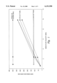
- FIG. 1 is a graph of the mean flow velocity versus the gain, the speed of sound and the standard deviation of the travel time difference of the ultrasonic flowmeter for normal liquid-free service.
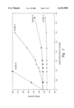
- FIG. 2 is a graph of the liquid fraction versus the gain of the ultrasonic flowmeter.
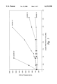
- FIG. 3 is a graph of the liquid fraction versus the standard deviation of the travel time difference ( ⁇ t) of the ultrasonic flowmeter.
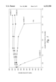
- FIG. 4 is a graph of the liquid volume versus the calibration shift of the ultrasonic flowmeter.
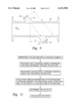
- FIG. 5 is a graph of the liquid fraction versus the sound velocity associated with the ultrasonic flowmeter for a gas velocity of 10 meters per second.
- FIG. 6 is a graph of the liquid fraction versus the sound velocity associated with the ultrasonic flowmeter for several gas velocities.
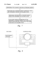
- FIG. 7 is a flow chart illustrating one embodiment of the method of determining the liquid fraction in a volume of gas as practiced by the present invention.
- FIG. 8 is an overview illustration of an apparatus employing the present invention.
- FIG. 9 is a perspective cross-section of a pipe illustrating one embodiment of the orientation of transducers which could be used in association with the present invention.
- FIG. 10 is a diagram illustrating electronics associated with the apparatus of the present invention.
- FIG. 11 is a flow chart illustrating one embodiment of the method of determining the flow rate associated with the liquid fraction in a volume of gas as well as the gas as practiced by the present invention.
- FIG. 1 is a graph of the mean flow velocity versus the gain, the speed of sound and the standard deviation of the travel time difference of the ultrasonic flowmeter for normal liquid-free service.
- FIG. 1 illustrates that a volume of gas which is free of moisture. The attenuation/gain characteristic and the speed of sound are constant. However, the standard deviation of the travel time difference ( ⁇ ( ⁇ t)) varies.
- FIG. 1 illustrates a base condition. Particularly as shown in FIG. 1, the speed of sound is unaffected by the flow velocity. Also in FIG. 1, the amplifier gains associated with the equipment are unaffected by flow velocity when no liquid is present in the volume of gas. The standard deviation of the travel time difference ( ⁇ t) is affected by flow velocity, in roughly the magnitudes shown, for a 150-mm meter.
- FIG. 2 is a graph of the liquid fraction versus the gain of the ultrasonic flow meter.
- the signal gain is controlled.
- the meter electronics attempts to maintain signals at a constant amplitude so that digitization is readily accomplished.
- the amplifier gain of the receiver is boosted to overcome the attenuation.
- the transmitted signal power will remain constant.
- the amplifier gain associated with the receiver is a measure of attenuation.
- FIG. 2 illustrates that the attenuation along chord D is greater than any other chord.
- the attenuation along chord C illustrates the next highest attenuation, and the attenuation along chord B is yet still lower, as is the attenuation along chord A.
- the meter used to acquire the data illustrated in FIG. 2 was horizontally arranged such that chord D was at the bottom of the meter, chord C was slightly above chord D, chord B was slightly above chord C, and chord A was above chord B.
- the data of FIG. 2 is readily explainable to gravitational effects. Gravity keeps the misting of the condensate dense around the bottom of the meter, i.e., in the vicinity of chords D and C.
- the mixture traveling along the top of the associated meter is significantly less dense as illustrated by the data associated with chords A and B.
- FIG. 3 is a graph of the liquid fraction versus the deviation of the travel time difference of the ultrasonic flow meter.
- the standard deviation of the travel time difference ( ⁇ t) measurements associated with FIG. 3 is caused by increased liquid fraction.
- the data in FIG. 3 illustrates that the effect is greatest at the bottom of the meter, near chords C and D, and less at the top of the meter, near chords A and B.
- the high liquid fraction increases the standard deviation from approximately 300 nanoseconds in dry gas to approximately 1800 nanoseconds with respect to chords D and C with liquid.
- FIGS. 2, 3, and 5 illustrate the gradients between chords.
- the gradients between chords are readily available for use as data in practicing the present invention.
- a gradient between chords can be used.
- a difference between gradients can be used.
- the standard deviation of a gradient between chords can be used.
- the standard deviation of the difference between gradients between chords can be used.
- other parameters can be adapted for use in practicing the present invention.
- FIG. 4 is a graph of the liquid volume versus the calibration shift of the ultrasonic flow meter.
- the calibration shift is also termed the meter over-reading.
- the calibration shift is provided as a function of the liquid volume for various flow rates in FIG. 4.
- the data provided a marked distinction between stratified flow and mist flow.
- stratified flow the liquid hold up of the stratified flow causes a significant gas measurement error. It has been determined that the gas measurement error associated with the stratified flow situation is about 4.5% for every 1% of liquid volume.
- the mist droplets are carried at the same flow rate as the gas.
- the calibration shift is approximately 1% for each 1% of liquid volume.
- FIG. 5 is a graph of the liquid fraction versus the sound velocity associated with the ultrasonic flow meter of the present invention.
- FIG. 5 illustrates the sound velocity measured on each chord at a flow velocity of 10 meters per second. Chords A and B are essentially unaffected at these levels. However, chords C and D show a definite dependence on the relative liquid content in the volume of gas. It should be noted that the maximum change of the velocity of sound was approximately 8 meters per second, or 2%.
- FIG. 6 is a graph of the liquid fraction versus the sound velocity associated with the ultrasonic flow meter of the present invention.
- the velocity of sound for chord C and D is plotted for various flow velocities.
- a comparison of the curves measured at approximately 5 meters per second and those of higher flows is important. It is anticipated that the flow crosses from a stratified situation to a mist flow situation somewhere between 5 and 10 meters per second.
- the present invention provides for the discovery that various parameters of a measured ultrasonic signal transmitted through a volume of gas has certain variations which are a function of the liquid fraction in the gas.
- a method can be provided whereby the percentage of a liquid present in a volume of gas can be determined. The method comprises the steps of impressing the volume of gas with ultrasonic energy, receiving the ultrasonic energy impressed upon and traversed through the volume of gas, measuring the received ultrasonic energy which has traversed the volume of gas, and evaluating various parameters of the measured ultrasonic energy for variations which are a function of the liquid fraction in the volume of gas.
- FIG. 8 is a general illustration of a representative apparatus for employing the present invention.
- FIG. 9 is a perspective cross-section of a pipe illustrating one embodiment of the orientation of transducers which could be used in practicing the present invention.
- the pipe 102 is adapted for receiving the transducers 104, 106.
- the transducers 104, 106 are displaced on opposite sides of the pipe 102 by a distance L between each transducer.
- the transducers 104, 106 are longitudinally displaced by a distance of X.
- the pipe 102 has ports 112, 114 for receiving the transducers 104, 106, respectively.
- FIG. 10 is a block diagram illustrating the apparatus 200 of the present invention.
- the apparatus 200 of the present invention comprises a clock 202, a counter 204, a transmitter 206, a first transducer 208, a memory 210, a controller 212, an analog-to-digital converter 214, a receiver 216, and a second transducer 218.
- the clock 202 is used for timing.
- the transmitter 206 is fired.
- the apparatus 200 starts digitizing.
- the A/D converter 214 is activated.
- the counter 204 starts counting.
- the A/D converter 214 places a magnitude from the receiver 216 into the next location in the memory 210.
- the memory 210 may develop curves as illustrated in FIGS. 2, 3, and 5. It is appreciated by those skilled in the art that all available phenomena are typically evaluated. Evaluating all relevant phenomena, including without limitation data illustrated in FIGS. 2, 3, and 5, provides a level of confidence in the date.
- the data accumulated in the memory 210 is processed as previously discussed to determine the time measurement.
- the apparatus 200 illustrated in FIG. 10 indicates there are dual transducers 208, 218, it can be appreciated that a single transducer may be readily adapted for practicing the present invention.
- a single transceiver device may be used to measure an attenuated signal.
- various system arrangements are readily available for practicing the present invention. Additional circuitry can be used to alternate the transmitter 206 and the receiver 218.
- techniques or equipment can be readily adapted by those skilled in the art to delay the start of the A/D converter 214 until a later time prior to the arrival of the signal.
- the same device can be used to determine the flow rate and the fractions.
- the present invention can also be practiced by using the present fraction meter in association with another type of flow rate meter, i.e., not an ultrasonic meter.
- the orientation of the meter is independent with respect to practicing the present invention.
- the meter could be oriented horizontally, vertically or at an intermediate orientation.
- a method of determining the percentage of a fluid present in a volume of gas comprises the steps of impressing the volume of gas with ultrasonic energy, receiving the ultrasonic energy impressed upon and traversing the volume of gas, measuring the received ultrasonic energy which has traversed the volume of gas, evaluating various parameters of the measured ultrasonic energy for variations which variations are a function of the liquid fraction in the volume of gas.
- the step of impressing the volume of gas with ultrasonic energy includes transmitting vibrations through the volume of gas.
- the step of transmitting vibrations through the volume of gas comprises ultrasonic frequencies through the volume of gas.
- the step of measuring the received ultrasonic energy which has traversed the volume of gas provides for transducing the signal for generating an electronic signal.
- the step of evaluating various parameters of the measured ultrasonic energy for variations provides for evaluating the gain associated with the measured signal for variations. The variations associated with the gain are a function of the liquid fraction in the volume of gas.
- the step of evaluating various parameters of the measured ultrasonic energy for variations includes evaluating the standard deviation of the travel time difference associated with the measured signal for variations which variations are a function of the liquid fraction in the volume of gas.
- the method provides for evaluating any stratified flow characteristics associated with the liquid fraction in the volume of gas such that the stratified flow characteristics are a function of the liquid fraction in the volume of gas.
- the method provides for evaluating any mist flow characteristics associated with the liquid fraction in the volume of gas such that the mist flow characteristics are a function of the liquid fraction in the volume of gas. The method of the present invention can determine which characteristics are appropriate for a particular situation.
- the method of the present invention of determining the percentage of a fluid present in a volume of gas is especially adaptable for use with natural gas.
- the variations of the parameters of the measured ultrasonic energy are a function of the liquid fraction in the volume of gas and provide a function applicable over a range of liquid fractions.
- the present invention provides an apparatus for determining the percentage of a fluid present in a volume of gas.
- the apparatus comprises a device for impressing the volume of gas with ultrasonic energy, a detector for receiving ultrasonic energy which has traversed the volume of gas, and a processor for evaluating various parameters of the measured ultrasonic energy for variations which variations are a function of the liquid fraction in the volume of gas. For example, particular variations of the measured signal correspond to, and are a function of, particular changes in the gain associated with the measured signal.
- the apparatus of the present invention can employ a typical ultrasonic flow meter.
- the apparatus has a processor for evaluating the mist flow characteristics or the stratified flow characteristics associated with the liquid fraction in the volume of gas as well as the gas velocity. The mist flow characteristics and the stratified flow characteristics are a function of the liquid fraction in the volume of gas.
- FIG. 11 illustrates the embodiment of the present invention wherein the gas and liquid flow rates are calculated.
- FIG. 11 is descriptive of a mixture having a gas fraction and a liquid fraction, both fractions termed fluid.
- the mixture is impressed with ultrasonic energy.
- the received ultrasonic energy is received and measured.
- Various parameters of the measured ultrasonic energy are evaluated for variations.
- the variations are a function of a fluid fraction in the mixture.
- the velocity is determined.
- a flow rate is calculated. It is appreciated by those skilled in the art that the calculated flow rate can be for the gas fraction or the liquid fraction, or both.
- the present invention provides for the measurement of the flow velocity of a fluid in a pipe comprising two or more transducers mounted on either side of the pipe and directed obliquely in relation to the direction of the flow, which transducers transmit and/or receive sonic pulses to and from each other.
Abstract
Description
Claims (22)
Priority Applications (3)
| Application Number | Priority Date | Filing Date | Title |
|---|---|---|---|
| US08/613,478 US6151958A (en) | 1996-03-11 | 1996-03-11 | Ultrasonic fraction and flow rate apparatus and method |
| US09/146,085 US6209388B1 (en) | 1996-03-11 | 1998-09-02 | Ultrasonic 2-phase flow apparatus and method |
| US09/388,253 US6386018B1 (en) | 1996-03-11 | 1999-09-01 | Ultrasonic 2-phase flow apparatus and stratified level detector |
Applications Claiming Priority (1)
| Application Number | Priority Date | Filing Date | Title |
|---|---|---|---|
| US08/613,478 US6151958A (en) | 1996-03-11 | 1996-03-11 | Ultrasonic fraction and flow rate apparatus and method |
Related Child Applications (1)
| Application Number | Title | Priority Date | Filing Date |
|---|---|---|---|
| US09/146,085 Continuation-In-Part US6209388B1 (en) | 1996-03-11 | 1998-09-02 | Ultrasonic 2-phase flow apparatus and method |
Publications (1)
| Publication Number | Publication Date |
|---|---|
| US6151958A true US6151958A (en) | 2000-11-28 |
Family
ID=24457474
Family Applications (1)
| Application Number | Title | Priority Date | Filing Date |
|---|---|---|---|
| US08/613,478 Expired - Lifetime US6151958A (en) | 1996-03-11 | 1996-03-11 | Ultrasonic fraction and flow rate apparatus and method |
Country Status (1)
| Country | Link |
|---|---|
| US (1) | US6151958A (en) |
Cited By (58)
| Publication number | Priority date | Publication date | Assignee | Title |
|---|---|---|---|---|
| US6732575B2 (en) * | 1998-06-26 | 2004-05-11 | Cidra Corporation | Fluid parameter measurement for industrial sensing applications using acoustic pressures |
| WO2004063741A2 (en) * | 2003-01-13 | 2004-07-29 | Cidra Corporation | Apparatus for measuring parameters of a flowing multiphase fluid mixture |
| US20040167735A1 (en) * | 2002-11-22 | 2004-08-26 | Paul Rothman | Method for calibrating a volumetric flow meter having an array of sensors |
| US20040168523A1 (en) * | 2002-11-12 | 2004-09-02 | Fernald Mark R. | Apparatus having an array of piezoelectric film sensors for measuring parameters of a process flow within a pipe |
| US20040199341A1 (en) * | 2003-01-21 | 2004-10-07 | Gysling Daniel L. | Measurement of entrained and dissolved gases in process flow lines |
| US20040210404A1 (en) * | 2003-01-21 | 2004-10-21 | Gysling Daniel L | Apparatus and method of measuring gas volume fraction of a fluid flowing within a pipe |
| US20040226386A1 (en) * | 2003-01-21 | 2004-11-18 | Gysling Daniel L. | Apparatus and method for measuring unsteady pressures within a large diameter pipe |
| US20040255695A1 (en) * | 2002-11-15 | 2004-12-23 | Gysling Daniel L. | Apparatus and method for providing a flow measurement compensated for entrained gas |
| US20050005712A1 (en) * | 2003-06-05 | 2005-01-13 | Gysling Daniel L. | Apparatus for measuring velocity and flow rate of a fluid having a non-negligible axial mach number using an array of sensors |
| US20050005713A1 (en) * | 2003-06-06 | 2005-01-13 | Winston Charles R. | Portable flow measurement apparatus having an array of sensors |
| US20050011258A1 (en) * | 2003-06-24 | 2005-01-20 | Gysling Daniel L. | System of distributed configurable flowmeters |
| US20050033545A1 (en) * | 2003-07-08 | 2005-02-10 | Gysling Daniel L. | Method and apparatus for measuring characteristics of core-annular flow |
| US20050044929A1 (en) * | 2003-07-15 | 2005-03-03 | Gysling Daniel L. | Apparatus and method for compensating a coriolis meter |
| US20050044966A1 (en) * | 2003-08-01 | 2005-03-03 | Gysling Daniel L. | Method and apparatus for measuring a parameter of a high temperature fluid flowing within a pipe using an array of piezoelectric based flow sensors |
| US20050050956A1 (en) * | 2003-06-24 | 2005-03-10 | Gysling Daniel L. | Contact-based transducers for characterizing unsteady pressures in pipes |
| US20050061060A1 (en) * | 2003-07-15 | 2005-03-24 | Gysling Daniel L. | Apparatus and method for providing a density measurement augmented for entrained gas |
| US6874361B1 (en) | 2004-01-08 | 2005-04-05 | Halliburton Energy Services, Inc. | Distributed flow properties wellbore measurement system |
| WO2005040732A1 (en) * | 2003-10-27 | 2005-05-06 | Elster-Instromet Ultrasonics B.V. | Wet gas measurement apparatus and method |
| US20050125170A1 (en) * | 2003-10-10 | 2005-06-09 | Gysling Daniel L. | Flow measurement apparatus having strain-based sensors and ultrasonic sensors |
| US20050120799A1 (en) * | 2003-06-24 | 2005-06-09 | Gysling Daniel L. | Contact-based transducers for characterizing unsteady pressures in pipes |
| US20050125169A1 (en) * | 2003-11-25 | 2005-06-09 | Loose Douglas H. | Method and apparatus for measuring a parameter of a fluid flowing within a pipe using sub-array processing |
| US20050125166A1 (en) * | 2003-10-09 | 2005-06-09 | Loose Douglas H. | Method and apparatus for measuring a parameter of a fluid flowing within a pipe using an array of sensors |
| US20050171710A1 (en) * | 2002-01-23 | 2005-08-04 | Cidra Corporation | Apparatus and method for measuring parameters of a mixture having solid particles suspended in a fluid flowing in a pipe |
| US20050193832A1 (en) * | 2003-02-10 | 2005-09-08 | Tombs Michael S. | Multi-phase Coriolis flowmeter |
| US20050227538A1 (en) * | 2004-03-23 | 2005-10-13 | Engel Thomas W | Piezocable based sensor for measuring unsteady pressures inside a pipe |
| US20060037385A1 (en) * | 2004-05-17 | 2006-02-23 | Gysling Daniel L | Apparatus and method for measuring compositional parameters of a mixture |
| US7059199B2 (en) | 2003-02-10 | 2006-06-13 | Invensys Systems, Inc. | Multiphase Coriolis flowmeter |
| US20060155391A1 (en) * | 2005-01-10 | 2006-07-13 | Nokia Corporation | User input device |
| US20060212231A1 (en) * | 2005-03-17 | 2006-09-21 | Bailey Timothy J | Apparatus and method of processing data to improve the performance of a flow monitoring system |
| US7146864B2 (en) | 2003-03-04 | 2006-12-12 | Cidra Corporation | Apparatus having a multi-band sensor assembly for measuring a parameter of a fluid flow flowing within a pipe |
| US7152003B2 (en) | 2003-12-11 | 2006-12-19 | Cidra Corporation | Method and apparatus for determining a quality metric of a measurement of a fluid parameter |
| US20070001028A1 (en) * | 2005-05-27 | 2007-01-04 | Gysling Daniel L | Apparatus and method for measuring a parameter of a multiphase flow |
| US20070005272A1 (en) * | 2005-05-16 | 2007-01-04 | Gysling Daniel L | Method and apparatus for detecting and characterizing particles in a multiphase fluid |
| US20070006744A1 (en) * | 2005-07-07 | 2007-01-11 | Gysling Daniel L | Wet gas metering using a differential pressure based flow meter with a sonar based flow meter |
| US20070044572A1 (en) * | 2005-07-13 | 2007-03-01 | Michael Davis | Method and apparatus for measuring parameters of a fluid flow using an array of sensors |
| US20070044571A1 (en) * | 2003-01-21 | 2007-03-01 | Gysling Daniel L | Apparatus and method of measuring gas volume fraction of a fluid flowing within a pipe |
| US20070157737A1 (en) * | 2005-05-27 | 2007-07-12 | Gysling Daniel L | Apparatus and method for measuring a parameter of a multiphase flow |
| US7249525B1 (en) | 2005-06-22 | 2007-07-31 | Cidra Corporation | Apparatus for measuring parameters of a fluid in a lined pipe |
| US7253742B2 (en) | 2003-08-01 | 2007-08-07 | Cidra Corporation | Method and apparatus for measuring parameters of a fluid flowing within a pipe using a configurable array of sensors |
| US20070234780A1 (en) * | 2003-01-21 | 2007-10-11 | Cidra Corporation | Total gas meter using speed of sound and velocity measurements |
| US20070279235A1 (en) * | 2003-08-01 | 2007-12-06 | Cidra Corporation | Method and apparatus for measuring parameters of a fluid flowing within a pipe using a configurable array of sensors |
| US20070294039A1 (en) * | 2006-05-16 | 2007-12-20 | Cidra Corporation | Apparatus and method for determining a parameter in a wet gas flow |
| US7340353B2 (en) | 2003-07-15 | 2008-03-04 | Cidra Corporation | Dual function flow measurement apparatus having an array of sensors |
| US7380438B2 (en) | 2004-09-16 | 2008-06-03 | Cidra Corporation | Apparatus and method for providing a fluid cut measurement of a multi-liquid mixture compensated for entrained gas |
| US7389187B2 (en) | 2003-01-13 | 2008-06-17 | Cidra Corporation | Apparatus and method using an array of ultrasonic sensors for determining the velocity of a fluid within a pipe |
| US7389687B2 (en) | 2004-11-05 | 2008-06-24 | Cidra Corporation | System for measuring a parameter of an aerated multi-phase mixture flowing in a pipe |
| US7426852B1 (en) | 2004-04-26 | 2008-09-23 | Expro Meters, Inc. | Submersible meter for measuring a parameter of gas hold-up of a fluid |
| US20080236298A1 (en) * | 2005-07-07 | 2008-10-02 | Cidra Corporation | Wet Gas Metering Using A Differential Pressure And A Sonar Based Flow Meter |
| US20090013799A1 (en) * | 2003-07-15 | 2009-01-15 | Cidra Corporation | Apparatus And Method For Augmenting A Coriolis Meter |
| US7624651B2 (en) | 2006-10-30 | 2009-12-01 | Expro Meters, Inc. | Apparatus and method for attenuating acoustic waves in pipe walls for clamp-on ultrasonic flow meter |
| US7624650B2 (en) | 2006-07-27 | 2009-12-01 | Expro Meters, Inc. | Apparatus and method for attenuating acoustic waves propagating within a pipe wall |
| US7673526B2 (en) | 2006-11-01 | 2010-03-09 | Expro Meters, Inc. | Apparatus and method of lensing an ultrasonic beam for an ultrasonic flow meter |
| US7752918B2 (en) | 2006-11-09 | 2010-07-13 | Expro Meters, Inc. | Apparatus and method for measuring a fluid flow parameter within an internal passage of an elongated body |
| WO2016133565A1 (en) * | 2015-02-19 | 2016-08-25 | Saudi Arabian Oil Company | Slug flow monitoring and gas measurement |
| CN112147620A (en) * | 2020-09-25 | 2020-12-29 | 上海应用技术大学 | System and method for measuring ultrasonic flight time in pipeline |
| CN113075292A (en) * | 2020-01-03 | 2021-07-06 | 广州汽车集团股份有限公司 | Method and device for measuring quality of automobile engine oil and storage medium |
| US11187044B2 (en) | 2019-12-10 | 2021-11-30 | Saudi Arabian Oil Company | Production cavern |
| US11460330B2 (en) | 2020-07-06 | 2022-10-04 | Saudi Arabian Oil Company | Reducing noise in a vortex flow meter |
Citations (13)
| Publication number | Priority date | Publication date | Assignee | Title |
|---|---|---|---|---|
| US3623363A (en) * | 1969-03-06 | 1971-11-30 | Realisations Ultrasoniques Sa | Ultrasonic flowmeter |
| US4080837A (en) * | 1976-12-03 | 1978-03-28 | Continental Oil Company | Sonic measurement of flow rate and water content of oil-water streams |
| US4138879A (en) * | 1977-08-22 | 1979-02-13 | Tif Instruments, Inc. | Sightless bubble detector |
| SU838552A1 (en) * | 1979-09-24 | 1981-06-15 | Харьковский Авиационный Институт Им.H.E.Жуковского | Device for measuring undissolved gas concentration in liquid |
| US4763525A (en) * | 1986-04-16 | 1988-08-16 | The Standard Oil Company | Apparatus and method for determining the quantity of gas bubbles in a liquid |
| USH608H (en) * | 1986-12-30 | 1989-03-07 | Shell Oil Company | Detecting multiple phase flow in a conduit |
| WO1993014382A1 (en) * | 1992-01-13 | 1993-07-22 | Jon Steinar Gudmundsson | Device and method for measuring multi phase flow |
| US5325703A (en) * | 1991-09-26 | 1994-07-05 | Siemens Aktiengesellschaft | Method for identifying the concentration of fuels or gases |
| US5415048A (en) * | 1994-06-27 | 1995-05-16 | Texaco Inc. | Acoustic gas-liquid flow meter |
| EP0691527A1 (en) * | 1994-07-05 | 1996-01-10 | Institut Français du Pétrole | Apparatus for method for measuring the velocity profile in a polyphase fluid |
| US5537854A (en) * | 1993-05-24 | 1996-07-23 | Phillips; Scott | Acoustic natural gas fuel sensor |
| US5714691A (en) * | 1994-11-02 | 1998-02-03 | Foster-Miller, Inc. | Method and system for analyzing a two phase flow |
| US5719329A (en) * | 1995-12-28 | 1998-02-17 | Ohio University | Ultrasonic measuring system and method of operation |
-
1996
- 1996-03-11 US US08/613,478 patent/US6151958A/en not_active Expired - Lifetime
Patent Citations (15)
| Publication number | Priority date | Publication date | Assignee | Title |
|---|---|---|---|---|
| US3623363A (en) * | 1969-03-06 | 1971-11-30 | Realisations Ultrasoniques Sa | Ultrasonic flowmeter |
| US4080837A (en) * | 1976-12-03 | 1978-03-28 | Continental Oil Company | Sonic measurement of flow rate and water content of oil-water streams |
| US4138879A (en) * | 1977-08-22 | 1979-02-13 | Tif Instruments, Inc. | Sightless bubble detector |
| SU838552A1 (en) * | 1979-09-24 | 1981-06-15 | Харьковский Авиационный Институт Им.H.E.Жуковского | Device for measuring undissolved gas concentration in liquid |
| US4763525A (en) * | 1986-04-16 | 1988-08-16 | The Standard Oil Company | Apparatus and method for determining the quantity of gas bubbles in a liquid |
| USH608H (en) * | 1986-12-30 | 1989-03-07 | Shell Oil Company | Detecting multiple phase flow in a conduit |
| US5325703A (en) * | 1991-09-26 | 1994-07-05 | Siemens Aktiengesellschaft | Method for identifying the concentration of fuels or gases |
| WO1993014382A1 (en) * | 1992-01-13 | 1993-07-22 | Jon Steinar Gudmundsson | Device and method for measuring multi phase flow |
| US5537854A (en) * | 1993-05-24 | 1996-07-23 | Phillips; Scott | Acoustic natural gas fuel sensor |
| US5415048A (en) * | 1994-06-27 | 1995-05-16 | Texaco Inc. | Acoustic gas-liquid flow meter |
| EP0691527A1 (en) * | 1994-07-05 | 1996-01-10 | Institut Français du Pétrole | Apparatus for method for measuring the velocity profile in a polyphase fluid |
| US5792962A (en) * | 1994-07-05 | 1998-08-11 | Institut Francais Du Petrole | Device and method for measuring velocity profiles in a multiphase fluid |
| US5714691A (en) * | 1994-11-02 | 1998-02-03 | Foster-Miller, Inc. | Method and system for analyzing a two phase flow |
| US5719329A (en) * | 1995-12-28 | 1998-02-17 | Ohio University | Ultrasonic measuring system and method of operation |
| US5719329B1 (en) * | 1995-12-28 | 1999-11-16 | Univ Ohio | Ultrasonic measuring system and method of operation |
Cited By (127)
| Publication number | Priority date | Publication date | Assignee | Title |
|---|---|---|---|---|
| US6988411B2 (en) * | 1998-06-26 | 2006-01-24 | Cidra Corporation | Fluid parameter measurement for industrial sensing applications using acoustic pressures |
| US6732575B2 (en) * | 1998-06-26 | 2004-05-11 | Cidra Corporation | Fluid parameter measurement for industrial sensing applications using acoustic pressures |
| US20050000289A1 (en) * | 1998-06-26 | 2005-01-06 | Gysling Daniel L. | Fluid parameter measurement for industrial sensing applications using acoustic pressures |
| US20050171710A1 (en) * | 2002-01-23 | 2005-08-04 | Cidra Corporation | Apparatus and method for measuring parameters of a mixture having solid particles suspended in a fluid flowing in a pipe |
| US7275421B2 (en) | 2002-01-23 | 2007-10-02 | Cidra Corporation | Apparatus and method for measuring parameters of a mixture having solid particles suspended in a fluid flowing in a pipe |
| US7400985B2 (en) | 2002-11-12 | 2008-07-15 | Cidra Corporation | Apparatus having an array of clamp on piezoelectric film sensors for measuring parameters of a process flow within a pipe |
| US20040168523A1 (en) * | 2002-11-12 | 2004-09-02 | Fernald Mark R. | Apparatus having an array of piezoelectric film sensors for measuring parameters of a process flow within a pipe |
| US20040168522A1 (en) * | 2002-11-12 | 2004-09-02 | Fernald Mark R. | Apparatus having an array of clamp on piezoelectric film sensors for measuring parameters of a process flow within a pipe |
| US7165464B2 (en) | 2002-11-15 | 2007-01-23 | Cidra Corporation | Apparatus and method for providing a flow measurement compensated for entrained gas |
| US20040255695A1 (en) * | 2002-11-15 | 2004-12-23 | Gysling Daniel L. | Apparatus and method for providing a flow measurement compensated for entrained gas |
| US7367240B2 (en) | 2002-11-15 | 2008-05-06 | Cidra Corporation | Apparatus and method for providing a flow measurement compensated for entrained gas |
| US20070067116A1 (en) * | 2002-11-22 | 2007-03-22 | Paul Rothman | Method for calibrating a volumetric flow meter having an array of sensors |
| US20040167735A1 (en) * | 2002-11-22 | 2004-08-26 | Paul Rothman | Method for calibrating a volumetric flow meter having an array of sensors |
| US7328113B2 (en) | 2002-11-22 | 2008-02-05 | Cidra Corporation | Method for calibrating a volumetric flow meter having an array of sensors |
| US7139667B2 (en) | 2002-11-22 | 2006-11-21 | Cidra Corporation | Method for calibrating a volumetric flow meter having an array of sensors |
| US7389187B2 (en) | 2003-01-13 | 2008-06-17 | Cidra Corporation | Apparatus and method using an array of ultrasonic sensors for determining the velocity of a fluid within a pipe |
| US20040194539A1 (en) * | 2003-01-13 | 2004-10-07 | Gysling Daniel L. | Apparatus for measuring parameters of a flowing multiphase mixture |
| US7096719B2 (en) | 2003-01-13 | 2006-08-29 | Cidra Corporation | Apparatus for measuring parameters of a flowing multiphase mixture |
| WO2004063741A3 (en) * | 2003-01-13 | 2004-09-23 | Cidra Corp | Apparatus for measuring parameters of a flowing multiphase fluid mixture |
| WO2004063741A2 (en) * | 2003-01-13 | 2004-07-29 | Cidra Corporation | Apparatus for measuring parameters of a flowing multiphase fluid mixture |
| US7617716B2 (en) | 2003-01-21 | 2009-11-17 | Cidra Corporate Services, Inc. | Total gas meter using speed of sound and velocity measurements |
| US20070062254A1 (en) * | 2003-01-21 | 2007-03-22 | Gysling Daniel L | Measurement of entrained and dissolved gases in process flow lines |
| US7343818B2 (en) | 2003-01-21 | 2008-03-18 | Cidra Corporation | Apparatus and method of measuring gas volume fraction of a fluid flowing within a pipe |
| US20080141756A1 (en) * | 2003-01-21 | 2008-06-19 | Cidra Corporation | Measurement of Entrained and Dissolved Gases in Process Flow Lines |
| US8109127B2 (en) | 2003-01-21 | 2012-02-07 | Cidra Corporate Services, Inc. | Measurement of entrained and dissolved gases in process flow lines |
| US20070234780A1 (en) * | 2003-01-21 | 2007-10-11 | Cidra Corporation | Total gas meter using speed of sound and velocity measurements |
| US7571633B2 (en) | 2003-01-21 | 2009-08-11 | Cidra Corporate Services, Inc. | Measurement of entrained and dissolved gases in process flow lines |
| US20070044571A1 (en) * | 2003-01-21 | 2007-03-01 | Gysling Daniel L | Apparatus and method of measuring gas volume fraction of a fluid flowing within a pipe |
| US20040226386A1 (en) * | 2003-01-21 | 2004-11-18 | Gysling Daniel L. | Apparatus and method for measuring unsteady pressures within a large diameter pipe |
| US20040210404A1 (en) * | 2003-01-21 | 2004-10-21 | Gysling Daniel L | Apparatus and method of measuring gas volume fraction of a fluid flowing within a pipe |
| US20040199341A1 (en) * | 2003-01-21 | 2004-10-07 | Gysling Daniel L. | Measurement of entrained and dissolved gases in process flow lines |
| US7058549B2 (en) | 2003-01-21 | 2006-06-06 | C1Dra Corporation | Apparatus and method for measuring unsteady pressures within a large diameter pipe |
| US7086278B2 (en) | 2003-01-21 | 2006-08-08 | Cidra Corporation | Measurement of entrained and dissolved gases in process flow lines |
| US7062976B2 (en) | 2003-01-21 | 2006-06-20 | Cidra Corporation | Apparatus and method of measuring gas volume fraction of a fluid flowing within a pipe |
| US7207229B2 (en) | 2003-02-10 | 2007-04-24 | Invensys Systems, Inc. | Multiphase Coriolis flowmeter |
| US7726203B2 (en) | 2003-02-10 | 2010-06-01 | Invensys Systems, Inc. | Multiphase Coriolis flowmeter |
| US7059199B2 (en) | 2003-02-10 | 2006-06-13 | Invensys Systems, Inc. | Multiphase Coriolis flowmeter |
| US20050193832A1 (en) * | 2003-02-10 | 2005-09-08 | Tombs Michael S. | Multi-phase Coriolis flowmeter |
| US7188534B2 (en) | 2003-02-10 | 2007-03-13 | Invensys Systems, Inc. | Multi-phase coriolis flowmeter |
| US8117921B2 (en) | 2003-02-10 | 2012-02-21 | Tombs Michael S | Multi-phase coriolis flowmeter |
| US20060161366A1 (en) * | 2003-02-10 | 2006-07-20 | Invensys Systems, Inc. | Multiphase coriolis flowmeter |
| US20080034892A1 (en) * | 2003-02-10 | 2008-02-14 | Invensys Systems, Inc. | Multi-phase coriolis flowmeter |
| US7698954B2 (en) | 2003-02-10 | 2010-04-20 | Invensys Systems, Inc. | Multi-phase Coriolis flowmeter |
| US7146864B2 (en) | 2003-03-04 | 2006-12-12 | Cidra Corporation | Apparatus having a multi-band sensor assembly for measuring a parameter of a fluid flow flowing within a pipe |
| US7197942B2 (en) | 2003-06-05 | 2007-04-03 | Cidra Corporation | Apparatus for measuring velocity and flow rate of a fluid having a non-negligible axial mach number using an array of sensors |
| US20050005712A1 (en) * | 2003-06-05 | 2005-01-13 | Gysling Daniel L. | Apparatus for measuring velocity and flow rate of a fluid having a non-negligible axial mach number using an array of sensors |
| US7302861B2 (en) | 2003-06-06 | 2007-12-04 | Cidra Corporation | Portable flow measurement apparatus having an array of sensors |
| US7121152B2 (en) | 2003-06-06 | 2006-10-17 | Cidra Corporation | Portable flow measurement apparatus having an array of sensors |
| US20070034017A1 (en) * | 2003-06-06 | 2007-02-15 | Winston Charles R | Portable flow measurement apparatus having an array of sensors |
| US20050005713A1 (en) * | 2003-06-06 | 2005-01-13 | Winston Charles R. | Portable flow measurement apparatus having an array of sensors |
| US7197938B2 (en) | 2003-06-24 | 2007-04-03 | Cidra Corporation | Contact-based transducers for characterizing unsteady pressures in pipes |
| US20050050956A1 (en) * | 2003-06-24 | 2005-03-10 | Gysling Daniel L. | Contact-based transducers for characterizing unsteady pressures in pipes |
| US7623976B2 (en) | 2003-06-24 | 2009-11-24 | Cidra Corporate Services, Inc. | System of distributed configurable flowmeters |
| US20050011258A1 (en) * | 2003-06-24 | 2005-01-20 | Gysling Daniel L. | System of distributed configurable flowmeters |
| US20050120799A1 (en) * | 2003-06-24 | 2005-06-09 | Gysling Daniel L. | Contact-based transducers for characterizing unsteady pressures in pipes |
| US7150202B2 (en) | 2003-07-08 | 2006-12-19 | Cidra Corporation | Method and apparatus for measuring characteristics of core-annular flow |
| US20050033545A1 (en) * | 2003-07-08 | 2005-02-10 | Gysling Daniel L. | Method and apparatus for measuring characteristics of core-annular flow |
| US20050061060A1 (en) * | 2003-07-15 | 2005-03-24 | Gysling Daniel L. | Apparatus and method for providing a density measurement augmented for entrained gas |
| US20090013799A1 (en) * | 2003-07-15 | 2009-01-15 | Cidra Corporation | Apparatus And Method For Augmenting A Coriolis Meter |
| US7596987B2 (en) | 2003-07-15 | 2009-10-06 | Expro Meters, Inc. | Apparatus and method for providing a density measurement augmented for entrained gas |
| US7152460B2 (en) | 2003-07-15 | 2006-12-26 | Cidra Corporation | Apparatus and method for compensating a coriolis meter |
| US7134320B2 (en) | 2003-07-15 | 2006-11-14 | Cidra Corporation | Apparatus and method for providing a density measurement augmented for entrained gas |
| US7793555B2 (en) | 2003-07-15 | 2010-09-14 | Expro Meters, Inc. | Apparatus and method for augmenting a coriolis meter |
| US7340353B2 (en) | 2003-07-15 | 2008-03-04 | Cidra Corporation | Dual function flow measurement apparatus having an array of sensors |
| US20050044929A1 (en) * | 2003-07-15 | 2005-03-03 | Gysling Daniel L. | Apparatus and method for compensating a coriolis meter |
| US7253742B2 (en) | 2003-08-01 | 2007-08-07 | Cidra Corporation | Method and apparatus for measuring parameters of a fluid flowing within a pipe using a configurable array of sensors |
| US20110203387A1 (en) * | 2003-08-01 | 2011-08-25 | Cidra Corporate Services Inc. | Method and Apparatus for Measuring Parameters of a Fluid Flowing within a Pipe Using a Configurable Array of Sensors |
| US20110208447A1 (en) * | 2003-08-01 | 2011-08-25 | Cidra Corporate Services Inc. | Method and Apparatus for Measuring Parameters of a Fluid Flowing within a Pipe Using a Configurable Array of Sensors |
| US8336393B2 (en) | 2003-08-01 | 2012-12-25 | Cidra Corporate Services Inc. | Method and apparatus for measuring parameters of a fluid flowing within a pipe using a configurable array of sensors |
| US20070279235A1 (en) * | 2003-08-01 | 2007-12-06 | Cidra Corporation | Method and apparatus for measuring parameters of a fluid flowing within a pipe using a configurable array of sensors |
| US8893558B2 (en) | 2003-08-01 | 2014-11-25 | Cidra Corporate Services, Inc. | Method and apparatus for measuring parameters of a fluid flowing within a pipe using a configurable array of sensors |
| US7322251B2 (en) | 2003-08-01 | 2008-01-29 | Cidra Corporation | Method and apparatus for measuring a parameter of a high temperature fluid flowing within a pipe using an array of piezoelectric based flow sensors |
| US20050044966A1 (en) * | 2003-08-01 | 2005-03-03 | Gysling Daniel L. | Method and apparatus for measuring a parameter of a high temperature fluid flowing within a pipe using an array of piezoelectric based flow sensors |
| US7882750B2 (en) | 2003-08-01 | 2011-02-08 | Cidra Corporate Services, Inc. | Method and apparatus for measuring parameters of a fluid flowing within a pipe using a configurable array of sensors |
| US20050125166A1 (en) * | 2003-10-09 | 2005-06-09 | Loose Douglas H. | Method and apparatus for measuring a parameter of a fluid flowing within a pipe using an array of sensors |
| US7110893B2 (en) | 2003-10-09 | 2006-09-19 | Cidra Corporation | Method and apparatus for measuring a parameter of a fluid flowing within a pipe using an array of sensors |
| US7237440B2 (en) | 2003-10-10 | 2007-07-03 | Cidra Corporation | Flow measurement apparatus having strain-based sensors and ultrasonic sensors |
| US20050125170A1 (en) * | 2003-10-10 | 2005-06-09 | Gysling Daniel L. | Flow measurement apparatus having strain-based sensors and ultrasonic sensors |
| US7430924B2 (en) | 2003-10-10 | 2008-10-07 | Expro Meters Inc. | Flow measurement apparatus having strain-based sensors and ultrasonic sensors |
| WO2005040732A1 (en) * | 2003-10-27 | 2005-05-06 | Elster-Instromet Ultrasonics B.V. | Wet gas measurement apparatus and method |
| US7171315B2 (en) | 2003-11-25 | 2007-01-30 | Cidra Corporation | Method and apparatus for measuring a parameter of a fluid flowing within a pipe using sub-array processing |
| US20050125169A1 (en) * | 2003-11-25 | 2005-06-09 | Loose Douglas H. | Method and apparatus for measuring a parameter of a fluid flowing within a pipe using sub-array processing |
| US7379828B2 (en) | 2003-12-11 | 2008-05-27 | Cidra Corporation | Method and apparatus for determining a quality metric of a measurement of a fluid parameter |
| US7152003B2 (en) | 2003-12-11 | 2006-12-19 | Cidra Corporation | Method and apparatus for determining a quality metric of a measurement of a fluid parameter |
| US20070118304A1 (en) * | 2003-12-11 | 2007-05-24 | Loose Douglas H | Method and apparatus for determining a quality metric of a measurement of a fluid parameter |
| US6874361B1 (en) | 2004-01-08 | 2005-04-05 | Halliburton Energy Services, Inc. | Distributed flow properties wellbore measurement system |
| US20050227538A1 (en) * | 2004-03-23 | 2005-10-13 | Engel Thomas W | Piezocable based sensor for measuring unsteady pressures inside a pipe |
| US7367239B2 (en) | 2004-03-23 | 2008-05-06 | Cidra Corporation | Piezocable based sensor for measuring unsteady pressures inside a pipe |
| US7426852B1 (en) | 2004-04-26 | 2008-09-23 | Expro Meters, Inc. | Submersible meter for measuring a parameter of gas hold-up of a fluid |
| US7363800B2 (en) | 2004-05-17 | 2008-04-29 | Cidra Corporation | Apparatus and method for measuring compositional parameters of a mixture |
| US20060037385A1 (en) * | 2004-05-17 | 2006-02-23 | Gysling Daniel L | Apparatus and method for measuring compositional parameters of a mixture |
| US7380438B2 (en) | 2004-09-16 | 2008-06-03 | Cidra Corporation | Apparatus and method for providing a fluid cut measurement of a multi-liquid mixture compensated for entrained gas |
| US7389687B2 (en) | 2004-11-05 | 2008-06-24 | Cidra Corporation | System for measuring a parameter of an aerated multi-phase mixture flowing in a pipe |
| US20060155391A1 (en) * | 2005-01-10 | 2006-07-13 | Nokia Corporation | User input device |
| US7440873B2 (en) | 2005-03-17 | 2008-10-21 | Expro Meters, Inc. | Apparatus and method of processing data to improve the performance of a flow monitoring system |
| US20060212231A1 (en) * | 2005-03-17 | 2006-09-21 | Bailey Timothy J | Apparatus and method of processing data to improve the performance of a flow monitoring system |
| US20070005272A1 (en) * | 2005-05-16 | 2007-01-04 | Gysling Daniel L | Method and apparatus for detecting and characterizing particles in a multiphase fluid |
| US7657392B2 (en) | 2005-05-16 | 2010-02-02 | Cidra Corporate Services, Inc. | Method and apparatus for detecting and characterizing particles in a multiphase fluid |
| US7437946B2 (en) | 2005-05-27 | 2008-10-21 | Cidra Corporation | Apparatus and method for measuring a parameter of a multiphase flow |
| US20070157737A1 (en) * | 2005-05-27 | 2007-07-12 | Gysling Daniel L | Apparatus and method for measuring a parameter of a multiphase flow |
| US7526966B2 (en) | 2005-05-27 | 2009-05-05 | Expro Meters, Inc. | Apparatus and method for measuring a parameter of a multiphase flow |
| US20070001028A1 (en) * | 2005-05-27 | 2007-01-04 | Gysling Daniel L | Apparatus and method for measuring a parameter of a multiphase flow |
| US7249525B1 (en) | 2005-06-22 | 2007-07-31 | Cidra Corporation | Apparatus for measuring parameters of a fluid in a lined pipe |
| US20080236298A1 (en) * | 2005-07-07 | 2008-10-02 | Cidra Corporation | Wet Gas Metering Using A Differential Pressure And A Sonar Based Flow Meter |
| US20070006727A1 (en) * | 2005-07-07 | 2007-01-11 | Gysling Daniel L | System and method for optimizing a gas/liquid separation process |
| US8641813B2 (en) | 2005-07-07 | 2014-02-04 | Expro Meters, Inc. | System and method for optimizing a gas/liquid separation process |
| US7603916B2 (en) | 2005-07-07 | 2009-10-20 | Expro Meters, Inc. | Wet gas metering using a differential pressure and a sonar based flow meter |
| US20070006744A1 (en) * | 2005-07-07 | 2007-01-11 | Gysling Daniel L | Wet gas metering using a differential pressure based flow meter with a sonar based flow meter |
| US7418877B2 (en) | 2005-07-07 | 2008-09-02 | Expro Meters, Inc. | Wet gas metering using a differential pressure based flow meter with a sonar based flow meter |
| US7503227B2 (en) | 2005-07-13 | 2009-03-17 | Cidra Corporate Services, Inc | Method and apparatus for measuring parameters of a fluid flow using an array of sensors |
| US20070044572A1 (en) * | 2005-07-13 | 2007-03-01 | Michael Davis | Method and apparatus for measuring parameters of a fluid flow using an array of sensors |
| US7454981B2 (en) | 2006-05-16 | 2008-11-25 | Expro Meters. Inc. | Apparatus and method for determining a parameter in a wet gas flow |
| US20070294039A1 (en) * | 2006-05-16 | 2007-12-20 | Cidra Corporation | Apparatus and method for determining a parameter in a wet gas flow |
| US7624650B2 (en) | 2006-07-27 | 2009-12-01 | Expro Meters, Inc. | Apparatus and method for attenuating acoustic waves propagating within a pipe wall |
| US7624651B2 (en) | 2006-10-30 | 2009-12-01 | Expro Meters, Inc. | Apparatus and method for attenuating acoustic waves in pipe walls for clamp-on ultrasonic flow meter |
| US7673526B2 (en) | 2006-11-01 | 2010-03-09 | Expro Meters, Inc. | Apparatus and method of lensing an ultrasonic beam for an ultrasonic flow meter |
| US7752918B2 (en) | 2006-11-09 | 2010-07-13 | Expro Meters, Inc. | Apparatus and method for measuring a fluid flow parameter within an internal passage of an elongated body |
| US9778226B2 (en) | 2015-02-19 | 2017-10-03 | Saudi Arabian Oil Company | Slug flow monitoring and gas measurement |
| WO2016133565A1 (en) * | 2015-02-19 | 2016-08-25 | Saudi Arabian Oil Company | Slug flow monitoring and gas measurement |
| US10473623B2 (en) | 2015-02-19 | 2019-11-12 | Saudi Arabian Oil Company | Slug flow monitoring and gas measurement |
| US11448618B2 (en) | 2015-02-19 | 2022-09-20 | Saudi Arabian Oil Company | Slug flow monitoring and gas measurement |
| US11782028B2 (en) | 2015-02-19 | 2023-10-10 | Saudi Arabian Oil Company | Slug flow monitoring and gas measurement |
| US11187044B2 (en) | 2019-12-10 | 2021-11-30 | Saudi Arabian Oil Company | Production cavern |
| CN113075292A (en) * | 2020-01-03 | 2021-07-06 | 广州汽车集团股份有限公司 | Method and device for measuring quality of automobile engine oil and storage medium |
| CN113075292B (en) * | 2020-01-03 | 2023-12-22 | 广州汽车集团股份有限公司 | Method and device for measuring quality of engine oil of automobile and storage medium |
| US11460330B2 (en) | 2020-07-06 | 2022-10-04 | Saudi Arabian Oil Company | Reducing noise in a vortex flow meter |
| CN112147620A (en) * | 2020-09-25 | 2020-12-29 | 上海应用技术大学 | System and method for measuring ultrasonic flight time in pipeline |
Similar Documents
| Publication | Publication Date | Title |
|---|---|---|
| US6151958A (en) | Ultrasonic fraction and flow rate apparatus and method | |
| Winkler et al. | Technique for measuring ultrasonic velocity and attenuation spectra in rocks under pressure | |
| US6971259B2 (en) | Fluid density measurement in pipes using acoustic pressures | |
| US6575043B1 (en) | Method and apparatus for characterizing flows based on attenuation of in-wall propagating wave modes | |
| JP3715647B2 (en) | Ultrasonic transducer with temporary crosstalk separation means | |
| EP0440701B1 (en) | Method and apparatus for measuring mass flow | |
| KR100208678B1 (en) | Apparatus for determining fluid flow | |
| US5415048A (en) | Acoustic gas-liquid flow meter | |
| Puttmer et al. | Ultrasonic density sensor for liquids | |
| US5365778A (en) | Method for measuring liquid viscosity and ultrasonic viscometer | |
| US7607358B2 (en) | Flow rate determination of a gas-liquid fluid mixture | |
| JP4800543B2 (en) | Method and apparatus for simultaneously measuring the flow rate and concentration of a multiphase liquid / gas mixture | |
| US4598593A (en) | Acoustic cross-correlation flowmeter for solid-gas flow | |
| JP2001526787A (en) | How to measure density and mass flow | |
| Ultrasonics | Industrial Applications of Ultrasound-A Review II. Measurements, Tests, and Process Control Using Low-Intensity Ultrasound | |
| US20040123666A1 (en) | Ultrasonic damping material | |
| US20090025487A1 (en) | Apparatus and method for attenuating acoustic waves in propagating within a pipe wall | |
| US20040011141A1 (en) | Method of and system for determining the mass flow rate of a fluid flowing in a conduit | |
| JP5629265B2 (en) | Ultrasonic flow meter | |
| US5271267A (en) | Method and apparatus for determining fluid properties from sonic/temperature fluid signature | |
| WO1988008516A1 (en) | Ultrasonic fluid flowmeter | |
| RU2298769C2 (en) | Device for determining and/or controlling volume and/or mass medium discharge in reservoir | |
| JP2006078362A (en) | Coaxial-type doppler ultrasonic current meter | |
| Eren | Accuracy in real time ultrasonic applications and transit-time flow meters | |
| Li et al. | Liquid flow measurement using silicone polymer wedge clamp-on ultrasonic transducers |
Legal Events
| Date | Code | Title | Description |
|---|---|---|---|
| AS | Assignment |
Owner name: DANIEL INDUSTRIES, INC., TEXAS Free format text: ASSIGNMENT OF ASSIGNORS INTEREST;ASSIGNORS:LETTON, WINSOR;ZANKER, KLAUS;REEL/FRAME:008762/0963;SIGNING DATES FROM 19971017 TO 19971021 |
|
| AS | Assignment |
Owner name: DANIEL INDUSTRIES, INC., TEXAS Free format text: ASSIGNMENT OF ASSIGNORS INTEREST;ASSIGNORS:LETTON, WINSOR;ZANKER, KLAUS J.;REEL/FRAME:010598/0722 Effective date: 20000204 |
|
| STCF | Information on status: patent grant |
Free format text: PATENTED CASE |
|
| FPAY | Fee payment |
Year of fee payment: 4 |
|
| FPAY | Fee payment |
Year of fee payment: 8 |
|
| FPAY | Fee payment |
Year of fee payment: 12 |