US6152350A - Ultrasonic welding device and method, and a magnetic tape cartridge reel welding device and method - Google Patents
Ultrasonic welding device and method, and a magnetic tape cartridge reel welding device and method Download PDFInfo
- Publication number
- US6152350A US6152350A US09/099,624 US9962498A US6152350A US 6152350 A US6152350 A US 6152350A US 9962498 A US9962498 A US 9962498A US 6152350 A US6152350 A US 6152350A
- Authority
- US
- United States
- Prior art keywords
- reel
- welding
- workpieces
- pressure
- ultrasonic
- Prior art date
- Legal status (The legal status is an assumption and is not a legal conclusion. Google has not performed a legal analysis and makes no representation as to the accuracy of the status listed.)
- Expired - Fee Related
Links
- 238000003466 welding Methods 0.000 title claims abstract description 289
- 238000000034 method Methods 0.000 title claims abstract description 55
- 238000002844 melting Methods 0.000 claims description 44
- 230000008018 melting Effects 0.000 claims description 44
- 238000006073 displacement reaction Methods 0.000 claims description 20
- 230000008859 change Effects 0.000 claims description 5
- 238000005259 measurement Methods 0.000 claims 4
- 238000004519 manufacturing process Methods 0.000 abstract description 3
- 229920005989 resin Polymers 0.000 description 19
- 239000011347 resin Substances 0.000 description 19
- 238000007796 conventional method Methods 0.000 description 15
- 230000002093 peripheral effect Effects 0.000 description 14
- 230000000694 effects Effects 0.000 description 13
- 239000000463 material Substances 0.000 description 12
- 239000000843 powder Substances 0.000 description 11
- 238000012360 testing method Methods 0.000 description 8
- 230000006835 compression Effects 0.000 description 7
- 238000007906 compression Methods 0.000 description 7
- 238000004804 winding Methods 0.000 description 7
- 238000003780 insertion Methods 0.000 description 6
- 230000037431 insertion Effects 0.000 description 6
- 238000004891 communication Methods 0.000 description 5
- 230000005284 excitation Effects 0.000 description 4
- 239000004417 polycarbonate Substances 0.000 description 4
- 229920000515 polycarbonate Polymers 0.000 description 4
- 230000004044 response Effects 0.000 description 4
- 238000001816 cooling Methods 0.000 description 3
- 230000002950 deficient Effects 0.000 description 3
- 239000003365 glass fiber Substances 0.000 description 3
- 230000007246 mechanism Effects 0.000 description 3
- 238000003825 pressing Methods 0.000 description 3
- 230000001603 reducing effect Effects 0.000 description 3
- 238000013016 damping Methods 0.000 description 2
- 230000007423 decrease Effects 0.000 description 2
- 238000001514 detection method Methods 0.000 description 2
- 239000000428 dust Substances 0.000 description 2
- 238000012986 modification Methods 0.000 description 2
- 230000004048 modification Effects 0.000 description 2
- 238000012544 monitoring process Methods 0.000 description 2
- 229920005668 polycarbonate resin Polymers 0.000 description 2
- 239000004431 polycarbonate resin Substances 0.000 description 2
- 238000002360 preparation method Methods 0.000 description 2
- 238000003892 spreading Methods 0.000 description 2
- 230000007480 spreading Effects 0.000 description 2
- 101000911772 Homo sapiens Hsc70-interacting protein Proteins 0.000 description 1
- 238000005520 cutting process Methods 0.000 description 1
- 230000003247 decreasing effect Effects 0.000 description 1
- 238000007667 floating Methods 0.000 description 1
- 238000009434 installation Methods 0.000 description 1
- 239000000155 melt Substances 0.000 description 1
- 239000002184 metal Substances 0.000 description 1
- 238000010137 moulding (plastic) Methods 0.000 description 1
- 230000010355 oscillation Effects 0.000 description 1
- 230000003449 preventive effect Effects 0.000 description 1
- 230000000630 rising effect Effects 0.000 description 1
- 229920003002 synthetic resin Polymers 0.000 description 1
- 239000000057 synthetic resin Substances 0.000 description 1
Images


Classifications
-
- B—PERFORMING OPERATIONS; TRANSPORTING
- B29—WORKING OF PLASTICS; WORKING OF SUBSTANCES IN A PLASTIC STATE IN GENERAL
- B29C—SHAPING OR JOINING OF PLASTICS; SHAPING OF MATERIAL IN A PLASTIC STATE, NOT OTHERWISE PROVIDED FOR; AFTER-TREATMENT OF THE SHAPED PRODUCTS, e.g. REPAIRING
- B29C66/00—General aspects of processes or apparatus for joining preformed parts
- B29C66/80—General aspects of machine operations or constructions and parts thereof
- B29C66/81—General aspects of the pressing elements, i.e. the elements applying pressure on the parts to be joined in the area to be joined, e.g. the welding jaws or clamps
- B29C66/816—General aspects of the pressing elements, i.e. the elements applying pressure on the parts to be joined in the area to be joined, e.g. the welding jaws or clamps characterised by the mounting of the pressing elements, e.g. of the welding jaws or clamps
- B29C66/8161—General aspects of the pressing elements, i.e. the elements applying pressure on the parts to be joined in the area to be joined, e.g. the welding jaws or clamps characterised by the mounting of the pressing elements, e.g. of the welding jaws or clamps said pressing elements being supported or backed-up by springs or by resilient material
-
- B—PERFORMING OPERATIONS; TRANSPORTING
- B23—MACHINE TOOLS; METAL-WORKING NOT OTHERWISE PROVIDED FOR
- B23K—SOLDERING OR UNSOLDERING; WELDING; CLADDING OR PLATING BY SOLDERING OR WELDING; CUTTING BY APPLYING HEAT LOCALLY, e.g. FLAME CUTTING; WORKING BY LASER BEAM
- B23K20/00—Non-electric welding by applying impact or other pressure, with or without the application of heat, e.g. cladding or plating
- B23K20/10—Non-electric welding by applying impact or other pressure, with or without the application of heat, e.g. cladding or plating making use of vibrations, e.g. ultrasonic welding
-
- B—PERFORMING OPERATIONS; TRANSPORTING
- B29—WORKING OF PLASTICS; WORKING OF SUBSTANCES IN A PLASTIC STATE IN GENERAL
- B29C—SHAPING OR JOINING OF PLASTICS; SHAPING OF MATERIAL IN A PLASTIC STATE, NOT OTHERWISE PROVIDED FOR; AFTER-TREATMENT OF THE SHAPED PRODUCTS, e.g. REPAIRING
- B29C65/00—Joining or sealing of preformed parts, e.g. welding of plastics materials; Apparatus therefor
- B29C65/02—Joining or sealing of preformed parts, e.g. welding of plastics materials; Apparatus therefor by heating, with or without pressure
- B29C65/08—Joining or sealing of preformed parts, e.g. welding of plastics materials; Apparatus therefor by heating, with or without pressure using ultrasonic vibrations
-
- B—PERFORMING OPERATIONS; TRANSPORTING
- B29—WORKING OF PLASTICS; WORKING OF SUBSTANCES IN A PLASTIC STATE IN GENERAL
- B29C—SHAPING OR JOINING OF PLASTICS; SHAPING OF MATERIAL IN A PLASTIC STATE, NOT OTHERWISE PROVIDED FOR; AFTER-TREATMENT OF THE SHAPED PRODUCTS, e.g. REPAIRING
- B29C65/00—Joining or sealing of preformed parts, e.g. welding of plastics materials; Apparatus therefor
- B29C65/74—Joining or sealing of preformed parts, e.g. welding of plastics materials; Apparatus therefor by welding and severing, or by joining and severing, the severing being performed in the area to be joined, next to the area to be joined, in the joint area or next to the joint area
- B29C65/749—Removing scrap
-
- B—PERFORMING OPERATIONS; TRANSPORTING
- B29—WORKING OF PLASTICS; WORKING OF SUBSTANCES IN A PLASTIC STATE IN GENERAL
- B29C—SHAPING OR JOINING OF PLASTICS; SHAPING OF MATERIAL IN A PLASTIC STATE, NOT OTHERWISE PROVIDED FOR; AFTER-TREATMENT OF THE SHAPED PRODUCTS, e.g. REPAIRING
- B29C65/00—Joining or sealing of preformed parts, e.g. welding of plastics materials; Apparatus therefor
- B29C65/78—Means for handling the parts to be joined, e.g. for making containers or hollow articles, e.g. means for handling sheets, plates, web-like materials, tubular articles, hollow articles or elements to be joined therewith; Means for discharging the joined articles from the joining apparatus
- B29C65/7841—Holding or clamping means for handling purposes
- B29C65/7847—Holding or clamping means for handling purposes using vacuum to hold at least one of the parts to be joined
-
- B—PERFORMING OPERATIONS; TRANSPORTING
- B29—WORKING OF PLASTICS; WORKING OF SUBSTANCES IN A PLASTIC STATE IN GENERAL
- B29C—SHAPING OR JOINING OF PLASTICS; SHAPING OF MATERIAL IN A PLASTIC STATE, NOT OTHERWISE PROVIDED FOR; AFTER-TREATMENT OF THE SHAPED PRODUCTS, e.g. REPAIRING
- B29C66/00—General aspects of processes or apparatus for joining preformed parts
- B29C66/01—General aspects dealing with the joint area or with the area to be joined
- B29C66/05—Particular design of joint configurations
- B29C66/10—Particular design of joint configurations particular design of the joint cross-sections
- B29C66/12—Joint cross-sections combining only two joint-segments; Tongue and groove joints; Tenon and mortise joints; Stepped joint cross-sections
- B29C66/128—Stepped joint cross-sections
- B29C66/1282—Stepped joint cross-sections comprising at least one overlap joint-segment
- B29C66/12821—Stepped joint cross-sections comprising at least one overlap joint-segment comprising at least two overlap joint-segments
-
- B—PERFORMING OPERATIONS; TRANSPORTING
- B29—WORKING OF PLASTICS; WORKING OF SUBSTANCES IN A PLASTIC STATE IN GENERAL
- B29C—SHAPING OR JOINING OF PLASTICS; SHAPING OF MATERIAL IN A PLASTIC STATE, NOT OTHERWISE PROVIDED FOR; AFTER-TREATMENT OF THE SHAPED PRODUCTS, e.g. REPAIRING
- B29C66/00—General aspects of processes or apparatus for joining preformed parts
- B29C66/01—General aspects dealing with the joint area or with the area to be joined
- B29C66/05—Particular design of joint configurations
- B29C66/10—Particular design of joint configurations particular design of the joint cross-sections
- B29C66/12—Joint cross-sections combining only two joint-segments; Tongue and groove joints; Tenon and mortise joints; Stepped joint cross-sections
- B29C66/128—Stepped joint cross-sections
- B29C66/1284—Stepped joint cross-sections comprising at least one butt joint-segment
-
- B—PERFORMING OPERATIONS; TRANSPORTING
- B29—WORKING OF PLASTICS; WORKING OF SUBSTANCES IN A PLASTIC STATE IN GENERAL
- B29C—SHAPING OR JOINING OF PLASTICS; SHAPING OF MATERIAL IN A PLASTIC STATE, NOT OTHERWISE PROVIDED FOR; AFTER-TREATMENT OF THE SHAPED PRODUCTS, e.g. REPAIRING
- B29C66/00—General aspects of processes or apparatus for joining preformed parts
- B29C66/01—General aspects dealing with the joint area or with the area to be joined
- B29C66/05—Particular design of joint configurations
- B29C66/20—Particular design of joint configurations particular design of the joint lines, e.g. of the weld lines
- B29C66/24—Particular design of joint configurations particular design of the joint lines, e.g. of the weld lines said joint lines being closed or non-straight
- B29C66/242—Particular design of joint configurations particular design of the joint lines, e.g. of the weld lines said joint lines being closed or non-straight said joint lines being closed, i.e. forming closed contours
- B29C66/2422—Particular design of joint configurations particular design of the joint lines, e.g. of the weld lines said joint lines being closed or non-straight said joint lines being closed, i.e. forming closed contours being circular, oval or elliptical
- B29C66/24221—Particular design of joint configurations particular design of the joint lines, e.g. of the weld lines said joint lines being closed or non-straight said joint lines being closed, i.e. forming closed contours being circular, oval or elliptical being circular
-
- B—PERFORMING OPERATIONS; TRANSPORTING
- B29—WORKING OF PLASTICS; WORKING OF SUBSTANCES IN A PLASTIC STATE IN GENERAL
- B29C—SHAPING OR JOINING OF PLASTICS; SHAPING OF MATERIAL IN A PLASTIC STATE, NOT OTHERWISE PROVIDED FOR; AFTER-TREATMENT OF THE SHAPED PRODUCTS, e.g. REPAIRING
- B29C66/00—General aspects of processes or apparatus for joining preformed parts
- B29C66/01—General aspects dealing with the joint area or with the area to be joined
- B29C66/05—Particular design of joint configurations
- B29C66/302—Particular design of joint configurations the area to be joined comprising melt initiators
- B29C66/3022—Particular design of joint configurations the area to be joined comprising melt initiators said melt initiators being integral with at least one of the parts to be joined
- B29C66/30223—Particular design of joint configurations the area to be joined comprising melt initiators said melt initiators being integral with at least one of the parts to be joined said melt initiators being rib-like
-
- B—PERFORMING OPERATIONS; TRANSPORTING
- B29—WORKING OF PLASTICS; WORKING OF SUBSTANCES IN A PLASTIC STATE IN GENERAL
- B29C—SHAPING OR JOINING OF PLASTICS; SHAPING OF MATERIAL IN A PLASTIC STATE, NOT OTHERWISE PROVIDED FOR; AFTER-TREATMENT OF THE SHAPED PRODUCTS, e.g. REPAIRING
- B29C66/00—General aspects of processes or apparatus for joining preformed parts
- B29C66/01—General aspects dealing with the joint area or with the area to be joined
- B29C66/32—Measures for keeping the burr form under control; Avoiding burr formation; Shaping the burr
- B29C66/322—Providing cavities in the joined article to collect the burr
-
- B—PERFORMING OPERATIONS; TRANSPORTING
- B29—WORKING OF PLASTICS; WORKING OF SUBSTANCES IN A PLASTIC STATE IN GENERAL
- B29C—SHAPING OR JOINING OF PLASTICS; SHAPING OF MATERIAL IN A PLASTIC STATE, NOT OTHERWISE PROVIDED FOR; AFTER-TREATMENT OF THE SHAPED PRODUCTS, e.g. REPAIRING
- B29C66/00—General aspects of processes or apparatus for joining preformed parts
- B29C66/50—General aspects of joining tubular articles; General aspects of joining long products, i.e. bars or profiled elements; General aspects of joining single elements to tubular articles, hollow articles or bars; General aspects of joining several hollow-preforms to form hollow or tubular articles
- B29C66/51—Joining tubular articles, profiled elements or bars; Joining single elements to tubular articles, hollow articles or bars; Joining several hollow-preforms to form hollow or tubular articles
- B29C66/53—Joining single elements to tubular articles, hollow articles or bars
- B29C66/534—Joining single elements to open ends of tubular or hollow articles or to the ends of bars
- B29C66/5344—Joining single elements to open ends of tubular or hollow articles or to the ends of bars said single elements being substantially annular, i.e. of finite length, e.g. joining flanges to tube ends
-
- B—PERFORMING OPERATIONS; TRANSPORTING
- B29—WORKING OF PLASTICS; WORKING OF SUBSTANCES IN A PLASTIC STATE IN GENERAL
- B29C—SHAPING OR JOINING OF PLASTICS; SHAPING OF MATERIAL IN A PLASTIC STATE, NOT OTHERWISE PROVIDED FOR; AFTER-TREATMENT OF THE SHAPED PRODUCTS, e.g. REPAIRING
- B29C66/00—General aspects of processes or apparatus for joining preformed parts
- B29C66/70—General aspects of processes or apparatus for joining preformed parts characterised by the composition, physical properties or the structure of the material of the parts to be joined; Joining with non-plastics material
- B29C66/71—General aspects of processes or apparatus for joining preformed parts characterised by the composition, physical properties or the structure of the material of the parts to be joined; Joining with non-plastics material characterised by the composition of the plastics material of the parts to be joined
-
- B—PERFORMING OPERATIONS; TRANSPORTING
- B29—WORKING OF PLASTICS; WORKING OF SUBSTANCES IN A PLASTIC STATE IN GENERAL
- B29C—SHAPING OR JOINING OF PLASTICS; SHAPING OF MATERIAL IN A PLASTIC STATE, NOT OTHERWISE PROVIDED FOR; AFTER-TREATMENT OF THE SHAPED PRODUCTS, e.g. REPAIRING
- B29C66/00—General aspects of processes or apparatus for joining preformed parts
- B29C66/70—General aspects of processes or apparatus for joining preformed parts characterised by the composition, physical properties or the structure of the material of the parts to be joined; Joining with non-plastics material
- B29C66/72—General aspects of processes or apparatus for joining preformed parts characterised by the composition, physical properties or the structure of the material of the parts to be joined; Joining with non-plastics material characterised by the structure of the material of the parts to be joined
- B29C66/721—Fibre-reinforced materials
- B29C66/7212—Fibre-reinforced materials characterised by the composition of the fibres
-
- B—PERFORMING OPERATIONS; TRANSPORTING
- B29—WORKING OF PLASTICS; WORKING OF SUBSTANCES IN A PLASTIC STATE IN GENERAL
- B29C—SHAPING OR JOINING OF PLASTICS; SHAPING OF MATERIAL IN A PLASTIC STATE, NOT OTHERWISE PROVIDED FOR; AFTER-TREATMENT OF THE SHAPED PRODUCTS, e.g. REPAIRING
- B29C66/00—General aspects of processes or apparatus for joining preformed parts
- B29C66/70—General aspects of processes or apparatus for joining preformed parts characterised by the composition, physical properties or the structure of the material of the parts to be joined; Joining with non-plastics material
- B29C66/73—General aspects of processes or apparatus for joining preformed parts characterised by the composition, physical properties or the structure of the material of the parts to be joined; Joining with non-plastics material characterised by the intensive physical properties of the material of the parts to be joined, by the optical properties of the material of the parts to be joined, by the extensive physical properties of the parts to be joined, by the state of the material of the parts to be joined or by the material of the parts to be joined being a thermoplastic or a thermoset
- B29C66/739—General aspects of processes or apparatus for joining preformed parts characterised by the composition, physical properties or the structure of the material of the parts to be joined; Joining with non-plastics material characterised by the intensive physical properties of the material of the parts to be joined, by the optical properties of the material of the parts to be joined, by the extensive physical properties of the parts to be joined, by the state of the material of the parts to be joined or by the material of the parts to be joined being a thermoplastic or a thermoset characterised by the material of the parts to be joined being a thermoplastic or a thermoset
- B29C66/7392—General aspects of processes or apparatus for joining preformed parts characterised by the composition, physical properties or the structure of the material of the parts to be joined; Joining with non-plastics material characterised by the intensive physical properties of the material of the parts to be joined, by the optical properties of the material of the parts to be joined, by the extensive physical properties of the parts to be joined, by the state of the material of the parts to be joined or by the material of the parts to be joined being a thermoplastic or a thermoset characterised by the material of the parts to be joined being a thermoplastic or a thermoset characterised by the material of at least one of the parts being a thermoplastic
- B29C66/73921—General aspects of processes or apparatus for joining preformed parts characterised by the composition, physical properties or the structure of the material of the parts to be joined; Joining with non-plastics material characterised by the intensive physical properties of the material of the parts to be joined, by the optical properties of the material of the parts to be joined, by the extensive physical properties of the parts to be joined, by the state of the material of the parts to be joined or by the material of the parts to be joined being a thermoplastic or a thermoset characterised by the material of the parts to be joined being a thermoplastic or a thermoset characterised by the material of at least one of the parts being a thermoplastic characterised by the materials of both parts being thermoplastics
-
- B—PERFORMING OPERATIONS; TRANSPORTING
- B29—WORKING OF PLASTICS; WORKING OF SUBSTANCES IN A PLASTIC STATE IN GENERAL
- B29C—SHAPING OR JOINING OF PLASTICS; SHAPING OF MATERIAL IN A PLASTIC STATE, NOT OTHERWISE PROVIDED FOR; AFTER-TREATMENT OF THE SHAPED PRODUCTS, e.g. REPAIRING
- B29C66/00—General aspects of processes or apparatus for joining preformed parts
- B29C66/80—General aspects of machine operations or constructions and parts thereof
- B29C66/81—General aspects of the pressing elements, i.e. the elements applying pressure on the parts to be joined in the area to be joined, e.g. the welding jaws or clamps
- B29C66/814—General aspects of the pressing elements, i.e. the elements applying pressure on the parts to be joined in the area to be joined, e.g. the welding jaws or clamps characterised by the design of the pressing elements, e.g. of the welding jaws or clamps
- B29C66/8141—General aspects of the pressing elements, i.e. the elements applying pressure on the parts to be joined in the area to be joined, e.g. the welding jaws or clamps characterised by the design of the pressing elements, e.g. of the welding jaws or clamps characterised by the surface geometry of the part of the pressing elements, e.g. welding jaws or clamps, coming into contact with the parts to be joined
- B29C66/81427—General aspects of the pressing elements, i.e. the elements applying pressure on the parts to be joined in the area to be joined, e.g. the welding jaws or clamps characterised by the design of the pressing elements, e.g. of the welding jaws or clamps characterised by the surface geometry of the part of the pressing elements, e.g. welding jaws or clamps, coming into contact with the parts to be joined comprising a single ridge, e.g. for making a weakening line; comprising a single tooth
-
- B—PERFORMING OPERATIONS; TRANSPORTING
- B29—WORKING OF PLASTICS; WORKING OF SUBSTANCES IN A PLASTIC STATE IN GENERAL
- B29C—SHAPING OR JOINING OF PLASTICS; SHAPING OF MATERIAL IN A PLASTIC STATE, NOT OTHERWISE PROVIDED FOR; AFTER-TREATMENT OF THE SHAPED PRODUCTS, e.g. REPAIRING
- B29C66/00—General aspects of processes or apparatus for joining preformed parts
- B29C66/80—General aspects of machine operations or constructions and parts thereof
- B29C66/82—Pressure application arrangements, e.g. transmission or actuating mechanisms for joining tools or clamps
- B29C66/824—Actuating mechanisms
- B29C66/8242—Pneumatic or hydraulic drives
-
- B—PERFORMING OPERATIONS; TRANSPORTING
- B29—WORKING OF PLASTICS; WORKING OF SUBSTANCES IN A PLASTIC STATE IN GENERAL
- B29C—SHAPING OR JOINING OF PLASTICS; SHAPING OF MATERIAL IN A PLASTIC STATE, NOT OTHERWISE PROVIDED FOR; AFTER-TREATMENT OF THE SHAPED PRODUCTS, e.g. REPAIRING
- B29C66/00—General aspects of processes or apparatus for joining preformed parts
- B29C66/80—General aspects of machine operations or constructions and parts thereof
- B29C66/83—General aspects of machine operations or constructions and parts thereof characterised by the movement of the joining or pressing tools
- B29C66/832—Reciprocating joining or pressing tools
- B29C66/8322—Joining or pressing tools reciprocating along one axis
-
- B—PERFORMING OPERATIONS; TRANSPORTING
- B29—WORKING OF PLASTICS; WORKING OF SUBSTANCES IN A PLASTIC STATE IN GENERAL
- B29C—SHAPING OR JOINING OF PLASTICS; SHAPING OF MATERIAL IN A PLASTIC STATE, NOT OTHERWISE PROVIDED FOR; AFTER-TREATMENT OF THE SHAPED PRODUCTS, e.g. REPAIRING
- B29C66/00—General aspects of processes or apparatus for joining preformed parts
- B29C66/90—Measuring or controlling the joining process
- B29C66/92—Measuring or controlling the joining process by measuring or controlling the pressure, the force, the mechanical power or the displacement of the joining tools
- B29C66/922—Measuring or controlling the joining process by measuring or controlling the pressure, the force, the mechanical power or the displacement of the joining tools by measuring the pressure, the force, the mechanical power or the displacement of the joining tools
- B29C66/9221—Measuring or controlling the joining process by measuring or controlling the pressure, the force, the mechanical power or the displacement of the joining tools by measuring the pressure, the force, the mechanical power or the displacement of the joining tools by measuring the pressure, the force or the mechanical power
-
- B—PERFORMING OPERATIONS; TRANSPORTING
- B29—WORKING OF PLASTICS; WORKING OF SUBSTANCES IN A PLASTIC STATE IN GENERAL
- B29C—SHAPING OR JOINING OF PLASTICS; SHAPING OF MATERIAL IN A PLASTIC STATE, NOT OTHERWISE PROVIDED FOR; AFTER-TREATMENT OF THE SHAPED PRODUCTS, e.g. REPAIRING
- B29C66/00—General aspects of processes or apparatus for joining preformed parts
- B29C66/90—Measuring or controlling the joining process
- B29C66/92—Measuring or controlling the joining process by measuring or controlling the pressure, the force, the mechanical power or the displacement of the joining tools
- B29C66/922—Measuring or controlling the joining process by measuring or controlling the pressure, the force, the mechanical power or the displacement of the joining tools by measuring the pressure, the force, the mechanical power or the displacement of the joining tools
- B29C66/9231—Measuring or controlling the joining process by measuring or controlling the pressure, the force, the mechanical power or the displacement of the joining tools by measuring the pressure, the force, the mechanical power or the displacement of the joining tools by measuring the displacement of the joining tools
- B29C66/92311—Measuring or controlling the joining process by measuring or controlling the pressure, the force, the mechanical power or the displacement of the joining tools by measuring the pressure, the force, the mechanical power or the displacement of the joining tools by measuring the displacement of the joining tools with special measurement means or methods
-
- B—PERFORMING OPERATIONS; TRANSPORTING
- B29—WORKING OF PLASTICS; WORKING OF SUBSTANCES IN A PLASTIC STATE IN GENERAL
- B29C—SHAPING OR JOINING OF PLASTICS; SHAPING OF MATERIAL IN A PLASTIC STATE, NOT OTHERWISE PROVIDED FOR; AFTER-TREATMENT OF THE SHAPED PRODUCTS, e.g. REPAIRING
- B29C66/00—General aspects of processes or apparatus for joining preformed parts
- B29C66/90—Measuring or controlling the joining process
- B29C66/92—Measuring or controlling the joining process by measuring or controlling the pressure, the force, the mechanical power or the displacement of the joining tools
- B29C66/924—Measuring or controlling the joining process by measuring or controlling the pressure, the force, the mechanical power or the displacement of the joining tools by controlling or regulating the pressure, the force, the mechanical power or the displacement of the joining tools
- B29C66/9241—Measuring or controlling the joining process by measuring or controlling the pressure, the force, the mechanical power or the displacement of the joining tools by controlling or regulating the pressure, the force, the mechanical power or the displacement of the joining tools by controlling or regulating the pressure, the force or the mechanical power
- B29C66/92441—Measuring or controlling the joining process by measuring or controlling the pressure, the force, the mechanical power or the displacement of the joining tools by controlling or regulating the pressure, the force, the mechanical power or the displacement of the joining tools by controlling or regulating the pressure, the force or the mechanical power the pressure, the force or the mechanical power being non-constant over time
- B29C66/92443—Measuring or controlling the joining process by measuring or controlling the pressure, the force, the mechanical power or the displacement of the joining tools by controlling or regulating the pressure, the force, the mechanical power or the displacement of the joining tools by controlling or regulating the pressure, the force or the mechanical power the pressure, the force or the mechanical power being non-constant over time following a pressure-time profile
- B29C66/92445—Measuring or controlling the joining process by measuring or controlling the pressure, the force, the mechanical power or the displacement of the joining tools by controlling or regulating the pressure, the force, the mechanical power or the displacement of the joining tools by controlling or regulating the pressure, the force or the mechanical power the pressure, the force or the mechanical power being non-constant over time following a pressure-time profile by steps
-
- B—PERFORMING OPERATIONS; TRANSPORTING
- B29—WORKING OF PLASTICS; WORKING OF SUBSTANCES IN A PLASTIC STATE IN GENERAL
- B29C—SHAPING OR JOINING OF PLASTICS; SHAPING OF MATERIAL IN A PLASTIC STATE, NOT OTHERWISE PROVIDED FOR; AFTER-TREATMENT OF THE SHAPED PRODUCTS, e.g. REPAIRING
- B29C66/00—General aspects of processes or apparatus for joining preformed parts
- B29C66/90—Measuring or controlling the joining process
- B29C66/92—Measuring or controlling the joining process by measuring or controlling the pressure, the force, the mechanical power or the displacement of the joining tools
- B29C66/929—Measuring or controlling the joining process by measuring or controlling the pressure, the force, the mechanical power or the displacement of the joining tools characterized by specific pressure, force, mechanical power or displacement values or ranges
- B29C66/9292—Measuring or controlling the joining process by measuring or controlling the pressure, the force, the mechanical power or the displacement of the joining tools characterized by specific pressure, force, mechanical power or displacement values or ranges in explicit relation to another variable, e.g. pressure diagrams
- B29C66/92921—Measuring or controlling the joining process by measuring or controlling the pressure, the force, the mechanical power or the displacement of the joining tools characterized by specific pressure, force, mechanical power or displacement values or ranges in explicit relation to another variable, e.g. pressure diagrams in specific relation to time, e.g. pressure-time diagrams
-
- B—PERFORMING OPERATIONS; TRANSPORTING
- B29—WORKING OF PLASTICS; WORKING OF SUBSTANCES IN A PLASTIC STATE IN GENERAL
- B29C—SHAPING OR JOINING OF PLASTICS; SHAPING OF MATERIAL IN A PLASTIC STATE, NOT OTHERWISE PROVIDED FOR; AFTER-TREATMENT OF THE SHAPED PRODUCTS, e.g. REPAIRING
- B29C66/00—General aspects of processes or apparatus for joining preformed parts
- B29C66/90—Measuring or controlling the joining process
- B29C66/95—Measuring or controlling the joining process by measuring or controlling specific variables not covered by groups B29C66/91 - B29C66/94
- B29C66/951—Measuring or controlling the joining process by measuring or controlling specific variables not covered by groups B29C66/91 - B29C66/94 by measuring or controlling the vibration frequency and/or the vibration amplitude of vibrating joining tools, e.g. of ultrasonic welding tools
- B29C66/9516—Measuring or controlling the joining process by measuring or controlling specific variables not covered by groups B29C66/91 - B29C66/94 by measuring or controlling the vibration frequency and/or the vibration amplitude of vibrating joining tools, e.g. of ultrasonic welding tools by controlling their vibration amplitude
-
- B—PERFORMING OPERATIONS; TRANSPORTING
- B29—WORKING OF PLASTICS; WORKING OF SUBSTANCES IN A PLASTIC STATE IN GENERAL
- B29C—SHAPING OR JOINING OF PLASTICS; SHAPING OF MATERIAL IN A PLASTIC STATE, NOT OTHERWISE PROVIDED FOR; AFTER-TREATMENT OF THE SHAPED PRODUCTS, e.g. REPAIRING
- B29C66/00—General aspects of processes or apparatus for joining preformed parts
- B29C66/90—Measuring or controlling the joining process
- B29C66/95—Measuring or controlling the joining process by measuring or controlling specific variables not covered by groups B29C66/91 - B29C66/94
- B29C66/954—Measuring or controlling the joining process by measuring or controlling specific variables not covered by groups B29C66/91 - B29C66/94 by measuring or controlling the thickness of the parts to be joined
-
- B—PERFORMING OPERATIONS; TRANSPORTING
- B29—WORKING OF PLASTICS; WORKING OF SUBSTANCES IN A PLASTIC STATE IN GENERAL
- B29C—SHAPING OR JOINING OF PLASTICS; SHAPING OF MATERIAL IN A PLASTIC STATE, NOT OTHERWISE PROVIDED FOR; AFTER-TREATMENT OF THE SHAPED PRODUCTS, e.g. REPAIRING
- B29C66/00—General aspects of processes or apparatus for joining preformed parts
- B29C66/90—Measuring or controlling the joining process
- B29C66/96—Measuring or controlling the joining process characterised by the method for implementing the controlling of the joining process
- B29C66/961—Measuring or controlling the joining process characterised by the method for implementing the controlling of the joining process involving a feedback loop mechanism, e.g. comparison with a desired value
-
- G—PHYSICS
- G11—INFORMATION STORAGE
- G11B—INFORMATION STORAGE BASED ON RELATIVE MOVEMENT BETWEEN RECORD CARRIER AND TRANSDUCER
- G11B23/00—Record carriers not specific to the method of recording or reproducing; Accessories, e.g. containers, specially adapted for co-operation with the recording or reproducing apparatus ; Intermediate mediums; Apparatus or processes specially adapted for their manufacture
- G11B23/02—Containers; Storing means both adapted to cooperate with the recording or reproducing means
- G11B23/037—Single reels or spools
-
- G—PHYSICS
- G11—INFORMATION STORAGE
- G11B—INFORMATION STORAGE BASED ON RELATIVE MOVEMENT BETWEEN RECORD CARRIER AND TRANSDUCER
- G11B23/00—Record carriers not specific to the method of recording or reproducing; Accessories, e.g. containers, specially adapted for co-operation with the recording or reproducing apparatus ; Intermediate mediums; Apparatus or processes specially adapted for their manufacture
- G11B23/02—Containers; Storing means both adapted to cooperate with the recording or reproducing means
- G11B23/04—Magazines; Cassettes for webs or filaments
- G11B23/08—Magazines; Cassettes for webs or filaments for housing webs or filaments having two distinct ends
- G11B23/107—Magazines; Cassettes for webs or filaments for housing webs or filaments having two distinct ends using one reel or core, one end of the record carrier coming out of the magazine or cassette
-
- B—PERFORMING OPERATIONS; TRANSPORTING
- B29—WORKING OF PLASTICS; WORKING OF SUBSTANCES IN A PLASTIC STATE IN GENERAL
- B29C—SHAPING OR JOINING OF PLASTICS; SHAPING OF MATERIAL IN A PLASTIC STATE, NOT OTHERWISE PROVIDED FOR; AFTER-TREATMENT OF THE SHAPED PRODUCTS, e.g. REPAIRING
- B29C66/00—General aspects of processes or apparatus for joining preformed parts
- B29C66/01—General aspects dealing with the joint area or with the area to be joined
- B29C66/05—Particular design of joint configurations
- B29C66/302—Particular design of joint configurations the area to be joined comprising melt initiators
- B29C66/3022—Particular design of joint configurations the area to be joined comprising melt initiators said melt initiators being integral with at least one of the parts to be joined
- B29C66/30221—Particular design of joint configurations the area to be joined comprising melt initiators said melt initiators being integral with at least one of the parts to be joined said melt initiators being point-like
-
- B—PERFORMING OPERATIONS; TRANSPORTING
- B29—WORKING OF PLASTICS; WORKING OF SUBSTANCES IN A PLASTIC STATE IN GENERAL
- B29C—SHAPING OR JOINING OF PLASTICS; SHAPING OF MATERIAL IN A PLASTIC STATE, NOT OTHERWISE PROVIDED FOR; AFTER-TREATMENT OF THE SHAPED PRODUCTS, e.g. REPAIRING
- B29C66/00—General aspects of processes or apparatus for joining preformed parts
- B29C66/90—Measuring or controlling the joining process
- B29C66/94—Measuring or controlling the joining process by measuring or controlling the time
- B29C66/944—Measuring or controlling the joining process by measuring or controlling the time by controlling or regulating the time
-
- B—PERFORMING OPERATIONS; TRANSPORTING
- B29—WORKING OF PLASTICS; WORKING OF SUBSTANCES IN A PLASTIC STATE IN GENERAL
- B29C—SHAPING OR JOINING OF PLASTICS; SHAPING OF MATERIAL IN A PLASTIC STATE, NOT OTHERWISE PROVIDED FOR; AFTER-TREATMENT OF THE SHAPED PRODUCTS, e.g. REPAIRING
- B29C66/00—General aspects of processes or apparatus for joining preformed parts
- B29C66/90—Measuring or controlling the joining process
- B29C66/94—Measuring or controlling the joining process by measuring or controlling the time
- B29C66/949—Measuring or controlling the joining process by measuring or controlling the time characterised by specific time values or ranges
-
- B—PERFORMING OPERATIONS; TRANSPORTING
- B29—WORKING OF PLASTICS; WORKING OF SUBSTANCES IN A PLASTIC STATE IN GENERAL
- B29C—SHAPING OR JOINING OF PLASTICS; SHAPING OF MATERIAL IN A PLASTIC STATE, NOT OTHERWISE PROVIDED FOR; AFTER-TREATMENT OF THE SHAPED PRODUCTS, e.g. REPAIRING
- B29C66/00—General aspects of processes or apparatus for joining preformed parts
- B29C66/90—Measuring or controlling the joining process
- B29C66/95—Measuring or controlling the joining process by measuring or controlling specific variables not covered by groups B29C66/91 - B29C66/94
- B29C66/951—Measuring or controlling the joining process by measuring or controlling specific variables not covered by groups B29C66/91 - B29C66/94 by measuring or controlling the vibration frequency and/or the vibration amplitude of vibrating joining tools, e.g. of ultrasonic welding tools
- B29C66/9513—Measuring or controlling the joining process by measuring or controlling specific variables not covered by groups B29C66/91 - B29C66/94 by measuring or controlling the vibration frequency and/or the vibration amplitude of vibrating joining tools, e.g. of ultrasonic welding tools characterised by specific vibration frequency values or ranges
-
- B—PERFORMING OPERATIONS; TRANSPORTING
- B29—WORKING OF PLASTICS; WORKING OF SUBSTANCES IN A PLASTIC STATE IN GENERAL
- B29C—SHAPING OR JOINING OF PLASTICS; SHAPING OF MATERIAL IN A PLASTIC STATE, NOT OTHERWISE PROVIDED FOR; AFTER-TREATMENT OF THE SHAPED PRODUCTS, e.g. REPAIRING
- B29C66/00—General aspects of processes or apparatus for joining preformed parts
- B29C66/90—Measuring or controlling the joining process
- B29C66/95—Measuring or controlling the joining process by measuring or controlling specific variables not covered by groups B29C66/91 - B29C66/94
- B29C66/951—Measuring or controlling the joining process by measuring or controlling specific variables not covered by groups B29C66/91 - B29C66/94 by measuring or controlling the vibration frequency and/or the vibration amplitude of vibrating joining tools, e.g. of ultrasonic welding tools
- B29C66/9517—Measuring or controlling the joining process by measuring or controlling specific variables not covered by groups B29C66/91 - B29C66/94 by measuring or controlling the vibration frequency and/or the vibration amplitude of vibrating joining tools, e.g. of ultrasonic welding tools characterised by specific vibration amplitude values or ranges
-
- B—PERFORMING OPERATIONS; TRANSPORTING
- B29—WORKING OF PLASTICS; WORKING OF SUBSTANCES IN A PLASTIC STATE IN GENERAL
- B29C—SHAPING OR JOINING OF PLASTICS; SHAPING OF MATERIAL IN A PLASTIC STATE, NOT OTHERWISE PROVIDED FOR; AFTER-TREATMENT OF THE SHAPED PRODUCTS, e.g. REPAIRING
- B29C66/00—General aspects of processes or apparatus for joining preformed parts
- B29C66/90—Measuring or controlling the joining process
- B29C66/95—Measuring or controlling the joining process by measuring or controlling specific variables not covered by groups B29C66/91 - B29C66/94
- B29C66/959—Measuring or controlling the joining process by measuring or controlling specific variables not covered by groups B29C66/91 - B29C66/94 characterised by specific values or ranges of said specific variables
- B29C66/9592—Measuring or controlling the joining process by measuring or controlling specific variables not covered by groups B29C66/91 - B29C66/94 characterised by specific values or ranges of said specific variables in explicit relation to another variable, e.g. X-Y diagrams
-
- B—PERFORMING OPERATIONS; TRANSPORTING
- B29—WORKING OF PLASTICS; WORKING OF SUBSTANCES IN A PLASTIC STATE IN GENERAL
- B29L—INDEXING SCHEME ASSOCIATED WITH SUBCLASS B29C, RELATING TO PARTICULAR ARTICLES
- B29L2017/00—Carriers for sound or information
- B29L2017/001—Carriers of records containing fine grooves or impressions, e.g. disc records for needle playback, cylinder records
- B29L2017/003—Records or discs
-
- B—PERFORMING OPERATIONS; TRANSPORTING
- B29—WORKING OF PLASTICS; WORKING OF SUBSTANCES IN A PLASTIC STATE IN GENERAL
- B29L—INDEXING SCHEME ASSOCIATED WITH SUBCLASS B29C, RELATING TO PARTICULAR ARTICLES
- B29L2031/00—Other particular articles
- B29L2031/704—Bobbins, spools
Definitions
- the present invention relates to an ultrasonic welding device which, when connecting together plastic moldings by ultrasonic welding, can provide the optimum connecting condition as well as a method for controlling welding in such ultrasonic welding.
- the present invention relates to a method and a device for welding together two reels into an integrally connected reel for use in a magnetic tape cartridge.
- the present invention relates to a method and a device for welding together upper and lower reels into a reel for use in a magnetic tape cartridge, in which the upper reel includes a reel hub with engagement means for rotation driving disposed on the bottom outer surface thereof, and a flange portion projecting in the radial direction of the upper reel from the lower end outer periphery of the reel hub; and, the lower reel includes a circular opening through which the bottom outer surface of the reel hub having the engagement means can be inserted, and a projecting rib to be welded. That is, the present invention relates to a welding device for welding the lower reel to the periphery of the engagement means of the reel hub of the upper reel.
- a magnetic tape cartridge used as a recording medium in a computer and the like there is known a structure of a type that a magnetic tape is wound on a single reel.
- This magnetic tape cartridge is used as the external memory of a computer, while important information is stored in the magnetic tape cartridge.
- the magnetic tape cartridge is structured such that not only it is free from troubles such as tape jamming and the like but also the magnetic tape thereof is prevented from being drawn out unpreparedly.
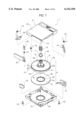
- FIG. 1 there is shown a conventional magnetic tape cartridge 1 which is used as the magnetic recording medium of a computer such as a tape streamer or the like.
- the conventional magnetic tape cartridge 1 is structured such that a magnetic tape 20 is wound on a single reel 3 composed of an upper reel 4 and a lower reel 5 connected together by ultrasonic welding, while the reel 3 is rotatably stored within a cartridge case which is composed of an upper cartridge 2a and a lower cartridge 2b fastened together by screws 19.
- the upper reel 4 is formed of polycarbonate resin with glass fibers contained therein and includes an upper flange 4a in the central portion of which there is formed a recessed portion 4b. Along the outer periphery of the upper flange 4a, there is formed a gear portion 4c.
- a ring-shaped bearing 6 is pressure inserted into and fixed to a cylindrical-shaped rib formed in the recessed portion 4b, while a spring plug 7 is pressure inserted into and fixed to a hole formed in the central portion of the bearing 6.
- a reel spring 8 is mounted on the spring plug 7, while the reel spring 8 presses against the reel 3 downwardly and holds the reel 3 in a freely rotatable manner.
- the lower reel 5 is formed of polycarbonate resin and includes a lower flange 5a; and, in the periphery of a hole formed in the central portion of the lower flange 5a, there is provided a projecting portion 5b for ultrasonic welding, while the projecting portion 5b is to be ultrasonically welded to the shoulder of the recessed portion 4b of the upper reel 4.
- the reel 3 when the cartridge is not in use, is secured by reel brakes 50 and 51, which are respectively energized properly by their associated torsion springs 12 for braking, so that the reel 3 is prevented against an unexpected rotation. Also, when the magnetic tape cartridge 1 is not in use, with the magnetic tape 20 wound completely on the reel 3, leader tape 21 (means which is used by a computer device for introducing the magnetic tape 20 into a tape passage) mounted on the end of the magnetic tape 20 is secured to the leading end portion of a hook 18 which is incorporated into the cartridge near the side face of the cartridge.
- leader tape 21 (means which is used by a computer device for introducing the magnetic tape 20 into a tape passage) mounted on the end of the magnetic tape 20 is secured to the leading end portion of a hook 18 which is incorporated into the cartridge near the side face of the cartridge.
- a lid 30 which is properly energized by a torsion spring 15 for lid energization and can be opened and closed in the cartridge plane direction.
- the lid 30 is secured by a lock member 40 which is properly energized by a compression spring 16 so that the lid 30 is prevented against rotation.
- a write protect 17 on the opposite side of the lid 30, there is incorporated a write protect 17.
- the projecting portion 5b which is provided along the peripheral edge of the opening or hole formed in the central portion of the lower flange 5a of the lower reel 5, is engaged with the shoulder of the peripheral edge of the downwardly projecting end of the recessed portion 4b of the upper reel 4; and, in this engaged state, by applying a given pressure between the projecting portion 5b and recessed portion 4b shoulder to thereby excite them ultrasonically, so that, while melting the projecting portion 5b, the two reels 4 and 5 are connected together.
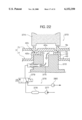
- FIG. 2 shows a welding device for working or welding the above-mentioned reel 3 ultrasonically.
- An ultrasonic welding device 60 shown in FIG. 2 comprises a working bed 61, a vertical frame 62 erected on one side of the bed 61, an air cylinder 63 suspended from the head portion of the vertical frame 62, a lifting frame 67 which is connected through a pressurization sensor 65 to a plunger 64 projecting into the lower portion of the air cylinder 63 and can be moved along a linear guide 66 disposed inside the vertical frame 62 in such a manner that it can be raised and lowered, an ultrasonic welder unit 68 supported vertically by the lifting frame 67, and a displacement sensor 69 for detecting the motion or displacement of the ultrasonic welder unit 68.
- the ultrasonic welder unit 68 is composed of three mutually continuing parts, that is, a converter 70, a booster 71 and a hone 72 to be contacted with a workpiece or a member to be worked, which are arranged sequentially in a descending order from the top of the ultrasonic welder unit 68.
- a receive base 74 On the other hand, on the upper surface of the bed 61, there is disposed a receive base 74 through a fine adjusting base 73. While one workpiece, that is, the upper reel 4 is fitted with and placed on the receive base 74 and the other workpiece, that is, the lower reel 5 is fitted with the upper surface of the upper reel 4, by lowering the ultrasonic welder unit 68, the two upper and lower reels 4 and 5 are pressurized and excited to thereby produce friction heat between them, so that the mutually connecting surfaces of the upper and lower reels 4 and 5 can be welded together.
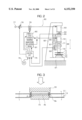
- the thus structured air cylinder 63 and ultrasonic welder unit 68 are driven and controlled by a control unit 75 which outputs such instructions to the air cylinder 63 and ultrasonic welder unit 68 as correspond to the information that is input therein from the pressurization sensor 65 and displacement sensor 69.
- the control unit 75 which is composed of a programmable controller or the like, not only can monitor variations in the respective parts during the reel working or welding operation in accordance with clock frequencies that are counted by a built-in timer, but also includes a display, a key board and the like (which are not shown) so that it is able to set various kinds of working or welding operations by inputting various numerical values.
- control unit 75 controls the air cylinder 63 in the following manner: that is, when a start switch 76 is turned on, while monitoring the detected condition from the load cell or pressurization sensor 65, the control unit 75 not only adjusts an air pressure supplied from an air cylinder driving air pressure source 77 to a given pressure through a pressure adjusting device 78 but also controls the air by opening or closing an electromagnetic valve 79; that is, when the electromagnetic valve 79 is opened, then the plunger 64 is projected to thereby lower the ultrasonic welder unit 68 down to a working or welding position, or when the electromagnetic valve 79 is closed, then the plunger 64 is retreated to its original position to thereby separate the ultrasonic welder unit 68 from the working or welding position.
- control unit 75 controls the ultrasonic welder unit 68 in the following manner: that is, when the start switch 76 is turned on, while monitoring the detected condition of the linear encoder or displacement sensor 69, the control unit 75 starts an oscillator power source 80 and, at the same time, excites the ultrasonic welder unit 68 with the amplitude that is adjusted and set through an amplitude adjusting device 81.
- the gap margin may be set sufficiently small from the beginning.
- the receive base 74 is structured such that the boss support portion 74b thereof is provided on and projected from the central position of the flange support portion 74a formed integrally therewith, when the upper reel 4 is placed on the upper portion of the boss support portion 74b and the flange portion 4a of the upper reel 4 is seated on the flange portion 74a of the receive base 74, they can be set in such a manner that there is produced a gap d between the top portion of the boss support portion 74b and the inner surface of the boss portion 4b due to the dimensional tolerance thereof or the like.
- the flange portion 4a can be set in such a manner that it is not seated on the flange support portion 74a but is separated therefrom.
- the ultrasonic welder unit after the lower reel 5 is mounted onto the upper reel 4 to thereby complete their setting, if the ultrasonic welder unit is lowered, then the upper and/or lower reels can be pushed by an amount corresponding to the gap d due to the collision inertia thereof, pressing forces applied in the working or welding operation, and the like, so that they can be deformed, which in turn causes the yield rate of the material to lower.
- the reel 4 can be vibrated while it is worked or welded, which, similarly to the above case, causes the yield rate of the material to lower.
- the above-mentioned magnetic tape cartridge is structured such that, as shown in FIG. 1, the magnetic tape 20 is wound on the single reel 3 composed of the upper reel 4 and lower reel 5 connected together by ultrasonic welding, while the reel 3 is rotatably stored within the cartridge case 2 which is composed of the upper cartridge 2a and lower cartridge 2b fastened together by the screws 19 or the like.
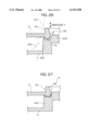
- the upper reel 4 of the above-mentioned single reel 3, as shown in FIGS. 5 and 6 as well, is composed of a reel hub 42 and a flange portion 43 which are united together into an integral body by means of synthetic resin: in particular, the reel hub 42 is formed in a bottomed cylindrical shape, and includes in the bottom portion outer surface thereof a plurality of securing teeth 42a serving as engagement means for rotation driving, and also includes a cylindrical portion 42b on the outer periphery of which the magnetic tape 20 can be wound; and, the flange portion 43 projects in the radial direction of the reel 4 from the outer periphery of the upper end of the reel hub 42, and includes in the outer peripheral edge thereof a plurality of restricting gears 43a with which the reel locks 50, 51 can be engaged when restricting the rotation of the reel 4 while the magnetic tape cartridge is not in use. As shown in FIG. 2, the bottomed recessed portion formed in the reel hub 42 is opened upwardly (in FIGS. 5 and 6, downwardly).
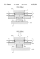
- the lower reel 5 is formed in a disk shape which includes in the central portion thereof a circular opening 5d for insertion of the above-mentioned securing teeth 42a therethrough and, on the periphery of the opening 5d, there is projectingly provided a welding rib 5c which can be butted against a welding contact portion (stepped surface) 42c annularly formed in the periphery of the securing teeth 42a. And, as shown in FIG. 6, while the welding rib 5c is assembled on the bottom portion of the reel hub 42 of the upper reel 4, the lower reel 5 can be welded ultrasonically to the upper reel 4 by an ultrasonic welding device (which will be discussed later).
- the above-mentioned reel 3 for a magnetic tape cartridge must have a high dimensional accuracy in order for the magnetic tape 20 to be able to run stably with high accuracy and, for this reason, the operation to connect the upper reel 4 and lower reel 5 to each other by welding must be carried out carefully.
- FIG. 7 shows a conventional welding device 160 which is used to weld together the above-mentioned upper reel 4 and lower reel 5.
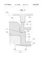
- the conventional welding device 160 comprises a welding receive base 161 for supporting the upper reel 4 in the reversed state in which the flange portion 43 is disposed in the lower portion thereof, so that the welding receive base 161 can support the upper reel 4 from the bottom portion inner surface side of the reel hub 42, and a welding horn 162 which, with the lower reel 5 assembled to the bottom portion of the reel hub 42 of the upper reel 4, presses the annular rib 5b of the lower reel 5 against the upper reel 4.
- the welding receive base 161 there is used either a receive base 164 structured such that it supports the upper reel 4 by means of a flange contact portion 163 thereof which can be contacted with the surface of the flange portion 43 of the upper reel 4, or a receive base 165 structured such that it supports the upper reel 4 by means of the upper end face 166 of a center projecting portion which can be fitted with the bottomed recessed portion of the reel hub 42, while the flange contact portion 163 and upper end face 166 are both formed in a flat surface.
- the flange contact portion 162a of the welding horn 162 which can be contacted with the annular rib 5b in order to apply the ultrasonic vibration energy to the welding rib 5c, is also formed in a flat surface.
- the upper reel 4 can be made to slip off in position in the radial direction thereof with respect to the welding receive base 161 or can be made to rotate with respect to the lower reel 5; that is, the upper reel 4 is not stabilized. This causes the upper and lower reels 4 and 5 to be welded unevenly, which in turn results in the lowered welding accuracy, the slippage of the surface of the lower reel, and other similar problems.
- the present inventors have studied the employment of a structure in which the welding receive base 161 is so arranged as to be fittable with the bottomed recessed portion of the reel hub 42 like the receive base 165 shown in FIG. 7, and the dimensional tolerance is reduced (for, example, down to 0.07 mm or less, preferably, down to 0.05 mm or less) so that the receive base 165 and reel hub 42 can be closely fitted with each other.
- the dimensional tolerance is reduced in this manner, it takes time and labor to mount the reel hub 42 onto the receive base 165 and remove the former from the latter, which makes it impossible to enhance the productivity.
- the center projecting portion of the receive base 165 is fitted and inserted into the bottomed recessed portion of the reel hub 42. If the dimensional tolerance is small, then not only the positioning accuracy of the upper reel 4 with respect to the receive base 165 must be enhanced but also it is difficult to exhaust the air within the bottomed recessed portion of the reel hub 42. That is, if the center projecting portion of the receive base 165 is quickly inserted into the bottomed recessed portion of the reel hub 42, then there is generated an insertion resistance between them. And, also when the integrally welded reel 3 for a magnetic tape cartridge is removed from the receive base 165, there is generated a removing resistance between them, which makes it impossible to take out the reel 3 quickly.
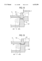
- the ultrasonic vibrations Y applied in the welding operation cause the respective contact portions of the upper and lower reels 4 and 5 (in particular, the respective contact portions of the welding rib 5c and welding contact portion 42c) to rub against each other, resulting in the shaved resin.
- shaved powder 85 produced due to such shaved resin is left between the upper and lower reels 4 and 5, then there is a possibility that the shaved powder 85 can attach to the magnetic tape wound on the reel 3, thereby raising a possibility that some signals can be missed in the recording and reproducing operation of the magnetic tape cartridge.
- the lump 91 of melted and hardened resin 90 causes damage to the magnetic tape that is to be wound on the outer periphery of the reel hub.
- the present invention is made based on the above-mentioned circumstances of the prior art. Accordingly, it is an object of the invention to provide a welding control method for use in an ultrasonic welding operation in which workpieces can be worked or welded together with a high yield rate and with enhanced productivity while restricting the deformation of the workpieces to thereby prevent the welded workpieces or products from varying in quality.
- a welding control method for use in an ultrasonic welding operation in which a horn is contacted with and pressed against a workpiece to thereby melt and weld the workpiece, wherein the amplitude of the horn is switched into a lower level in the middle of melting of the workpiece than the level thereof set at the start time of the ultrasonic welding operation of the workpiece.
- the amplitude may be preferably switched into the lower level before at least one half of the workpiece thickness to be melted until the workpiece is welded completely is melted.
- an apparatus operable to carry out the above-mentioned method may comprise amplitude switching means for switching the amplitude of an oscillator power source in two stages, that is, into a beginning amplitude and a later amplitude, detecting means for detecting the melted condition of the workpiece with the passage of the welding thereof, and switching control means which, in accordance with the detection results of the detecting means, drives the switching means to switch the amplitude of the oscillator power source from the beginning amplitude to the later amplitude.
- the two-stage amplitude control can be executed automatically according to the conditions that have been previously set.
- a welding control method for use in an ultrasonic welding operation in which the pressure to be applied to a workpiece in an ultrasonic welding operation is switched in the middle of melting of the workpiece into a lower level than the level thereof set at the start time of the welding operation of the workpiece.
- the amplitude may be preferably switched at a timing before at least one half of the workpiece thickness to be melted until the workpiece is welded completely is melted.
- an apparatus operable to carry out the above-mentioned method may comprise pressure switching means for switching the pressure of a pressure drive source into a plurality of stages, detecting means for detecting the melted condition of the workpiece with the passage of the welding thereof, and switching control means which, in accordance with the detection results of the detecting means, drives the switching means to execute the above-mentioned switching operation.
- the pressure control can be carried out automatically.
- both of the amplitude of the oscillator power source and the pressure to be applied to the workpiece may also be switched in such a manner that they are set large in the starting time of the welding operation of the workpiece and are switched into their respective lower levels in the middle of the welding operation of the workpiece.
- the welding operation of the workpiece can be executed with higher accuracy.
- the present invention aims at eliminating the problems found in the above-mentioned conventional ultrasonic welding devices. Accordingly, it is an object of the invention to provide an ultrasonic welding device which not only can facilitate the installation of a workpiece but also, in the working or welding condition thereof, can bring the workpiece into close contact with a receive base to thereby restrict the occurrence of the slippage of the workpiece with respect to the receive base.
- an ultrasonic welding device comprising: an ultrasonic welder unit which can be raised up to and lowered down to and from a working or welding position and is also composed of a converter, a booster and a horn; and, a receive base which is disposed at the working or welding position and opposed to the horn and is used to hold a workpiece in the leading end portion thereof in such a manner that the workpiece is fitted with the leading end portion thereof, wherein the leading end portion of the receive base can be expanded and compressed in the radial direction thereof.
- the leading end of the receive base when the workpiece is attached to the receive base, the leading end of the receive base can be compressed in the radial direction thereof to thereby prevent the wrong insertion of the workpiece, and, while the workpiece is being attached/inserted therein, the leading end of the receive base can be expanded in the radial direction thereof to thereby be able to minimize a gap between them.
- the present invention aims at solving the above-mentioned problems. Accordingly, it is an object of the invention to provide an ultrasonic welding device in which, in the ultrasonic welding operation thereof, the boss portion and flange portion of a workpiece can be closely contacted with the top portion of a boss support portion and a flange support portion respectively formed in a receive base disposed in the ultrasonic welding device, thereby being able to restrict the deformation of the workpiece which could be caused when pressure is applied to the workpiece.
- an ultrasonic welding device which comprises an ultrasonic welder unit raisable to and lowerable down from a working or welding position and including a converter, a booster and a horn, and a receive base disposed at the working or welding position and opposed to the horn for holding a workpiece in the leading end portion thereof in such a manner that the workpiece is fitted with the leading end portion thereof, wherein the receive base includes a flange support base for supporting the flange portion of the workpiece, and boss support portion projectingly provided in the central portion of the flange support base and fittable with the boss portion of the workpiece; the boss support portion of the receive base is disposed in such a manner that it can be lifted to and lowered down from the flange support base; and, there is provided energizing means for energizing the boss support portion in the lifting direction thereof.
- the boss support portion of the receive base holding the workpiece is lowered down together with the workpiece against the energizing force of the energizing means, and, if the flange portion of the workpiece is seated on the flange support portion of the receive base, then the workpiece can be worked or welded while it is held in this position.
- the present invention aims at eliminating the drawbacks found in the above-mentioned conventional ultrasonic welding device. Accordingly, it is an object of the invention to provide a magnetic tape cartridge reel welding device which not only allow a reel to be mounted onto and removed from a welding receive base simply and quickly to thereby be able to enhance the productivity thereof, but also, when the reel is welded ultrasonically, prevents the upper reel of the reel from slipping off in position with respect to the welding receive base and from rotating with respect to the lower reel of the reel, thereby being able to prevent the upper and lower reels from being welded together unevenly, so that a high-accuracy reel for a magnetic tape cartridge can be produced.
- a magnetic tape cartridge reel welding device which comprises: a welding receive base for supporting an upper reel from the bottom portion inner surface side of the reel hub of the upper reel, the upper reel being composed of the reel hub and a flange portion formed integrally with each other, the reel hub having a bottomed cylindrical shape and including engaging means for rotation driving on the outer surface of the bottom portion thereof, with a magnetic tape windable around the outer periphery of the cylindrical portion thereof, and the flange portion projecting in the radial direction of the reel hub from the outer periphery of the upper end of the reel hub; and, a welding horn for pressing a lower reel, which includes in the central portion thereof a circular opening for allowing the engaging means to be inserted therethrough, against the upper reel in such a manner that the lower reel is contacted with a welding contact portion formed in the periphery of the engaging means and is thereby assembled to the bottom portion of the reel hub, whereby ultrasonic vibration energy is applied
- the reel hub fixing means when the upper reel is set or mounted onto the welding receive base, by operating the reel hub fixing means to apply the draw-in force to the upper reel, the mounting of the upper reel can be attained more quickly. Also, in the ultrasonic welding operation, since the reel hub fixing means applies the draw-in force to the upper reel, the upper reel can be positively held and fixed onto the welding receive base, which prevents the upper reel from slipping off in position in the radial direction thereof with respect to the welding receive base or rotating with respect to the lower reel due to vibrations transmitted thereto from the welding horn. Further, when removing the upper reel from the welding receive base, the removal of the upper reel can be achieved more quickly.
- the present invention aims at solving the problems found in the above-mentioned conventional ultrasonic welding method and device. Accordingly, it is an object of the invention to provide method and device for manufacturing by ultrasonic welding a reel for use in a magnetic tape cartridge, which not only can remove effectively the shaved powder of shaved resin produced when upper and lower reels are connected together by ultrasonic welding, but also can prevent the melted resin from overflowing into a tape winding area in the welded portions of the reels.
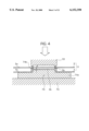
- a magnetic tape cartridge reel welding method in which an upper reel, which is composed of not only a reel hub having a bottomed cylindrical shape and including engaging means for rotation driving on the outer surface of the bottom portion thereof with a magnetic tape windable around the outer periphery of the cylindrical portion thereof but also a flange portion so formed as to project in the radial direction of the reel hub from the outer periphery of the upper end of the reel hub, is ultrasonically welded to a lower reel including a circular opening into which the bottom portion outer surface including the engaging portion can be inserted, thereby connecting the upper and lower reels into an integral body, characterized in that, in such a manner that the lower reel is contacted with a welding contact portion formed in the periphery of the engaging means and is thereby assembled to the bottom portion of the reel hub, the upper and lower reels are welded together ultrasonically while applying a negative pressure to the inner peripheral portion of the opening of the lower reel.
- a magnetic tape cartridge reel welding device which comprises: a welding receive base for supporting an upper reel from the inner surface side of the bottom portion of a reel hub of the upper reel, the upper reel being composed of not only the reel hub having a bottomed cylindrical shape and including engaging means for rotation driving on the outer surface of the bottom portion thereof with a magnetic tape windable around the outer periphery of the cylindrical portion thereof but also a flange portion so formed as to project in the radial direction of the reel hub from the outer periphery of the upper end of the reel hub; and, a welding horn for pressing a lower reel, which includes in the central portion thereof a circular opening for allowing the engaging means to be inserted therethrough, against the upper reel in such a manner that the lower reel is contacted with a welding contact portion formed in the periphery of the engaging means and is thereby assembled to the bottom portion of the reel hub, whereby ultrasonic vibration energy is applied from the welding horn to the portions of the upper
- FIG. 1 is an exploded perspective view of a conventional magnetic tape cartridge using a single reel
- FIG. 2 is a general view of a conventional ultrasonic welding device
- FIG. 3 is an enlarged view of a conventional receive base employed in the conventional ultrasonic welding device
- FIG. 4 is an enlarged view of another conventional receive base employed in the conventional ultrasonic welding device
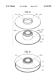
- FIG. 5 is an exploded perspective view of the magnetic tape cartridge reel shown in FIG. 1;
- FIG. 6 is a perspective view of the magnetic tape cartridge reel shown in FIG. 5, showing its assembling state
- FIG. 7 is a section view of the main portions of a conventional magnetic tape cartridge reel welding device
- FIG. 8 is a general explanatory view of the welded state of upper and lower reels obtained when they are welded ultrasonically using the conventional magnetic tape cartridge reel welding device shown in FIG. 7;
- FIG. 9 is also a general explanatory view of the welded state of upper and lower reels obtained when they are welded ultrasonically using the conventional magnetic tape cartridge reel welding device shown in FIG. 7;
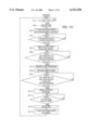
- FIG. 10 is a flow chart of a working procedure, according to the present invention, to be taken in the ultrasonic welding device shown in FIG. 2;
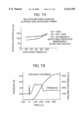
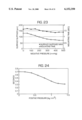
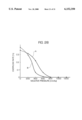
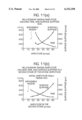
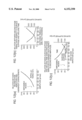
- FIG. 11(a) is a graphical representation of the relation of the amplitude variations with respect to the working time and surface slippage in the conventional welding method in which the amplitude is-set constant through the welding operation; and, FIG. 11(b) is a graphical representation of the relation of the second-stage amplitude variations with respect to the working time and surface slippage in a welding method according to the invention employing a two-stage amplitude switching system;
- FIG. 12(a) is a graphical representation of the relation between the second-stage amplitude variations and overshoot characteristics
- FIG. 12(b) a graphical representation of the relation between surface slippage and welding time with respect to the timing of the second-stage amplitude
- FIG. 12(c) is a graphical representation of the relation between surface slippage and welding time when the first-stage amplitude is caused to vary;
- FIG. 13 is a graphical representation of the relation of the amplitude variations with respect to the melting time and working time
- FIG. 14(a) is a graphical representation of the relation of the pressure variations with respect to the surface slippage when a constant pressure is applied in the conventional welding method
- FIG. 14(b) is a graphical representation of the relation between the second-stage pressure and surface slippage in a welding method according to the invention employing a two-stage pressure switching system
- FIG. 15 is a graphical representation of the relation between switching timings and surface slippage
- FIG. 16 is a graphical representation of the relation of the pressure variations with respect to the melting time and working time
- FIG. 17 is an exploded perspective view of a receive base employed in a second embodiment according to the invention.
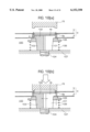
- FIG. 18(a) is an enlarged view of the main portions of the second embodiment, showing a state thereof in which upper and lower reels are mounted on the above receive base; and, FIG. 18(b) is an enlarged view of the main portions of the second embodiment, showing a state thereof, following the above state, in which a horn is pressed against the upper and lower reels mounted on the receive base;
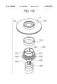
- FIG. 19 is an exploded perspective view of a receive base employed in a third embodiment according to the invention.
- FIG. 20(a) is an enlarged view of the main portions of a fourth embodiment according to the invention, showing a state thereof in which upper and lower reels are mounted on a receive base
- FIG. 20(b) is an enlarged view of the main portions of the fourth embodiment, showing a state thereof in which a horn is pressed against the upper and lower reels mounted on the receive base from the above state;
- FIG. 21 is an enlarged view of the main portions of a fifth embodiment according to the invention, showing a state thereof in which a horn is pressed against upper and lower reels mounted on a receive base;
- FIG. 22 is a section view of the main portions of a magnetic tape cartridge reel welding device according to a sixth embodiment of the invention.
- FIG. 23 is a graphical representation of the relation between the negative pressures of a reel hub fixing means and the surface slippage and mounting time of an upper reel in the sixth embodiment of the invention.
- FIG. 24 is a graphical representation of the relation between the positive pressures of the reel hub fixing means and the mounting and removing time of the upper reel in the sixth embodiment of the invention.
- FIG. 25 is a section view of the main portions of a magnetic tape cartridge reel welding device according to a seventh embodiment of the invention.
- FIG. 26 is a general explanatory view of the welded state of upper and lower reels obtained when they are welded together ultrasonically using the welding device shown in FIG. 25;
- FIG. 27 is also a general explanatory view of the welded state of the upper and lower reels obtained when they are welded together ultrasonically using the welding device shown in FIG. 25;
- FIG. 28 is a graphical representation of the relation between the negative pressures and the overflow rate of welded portions in an embodiment-enforced by a welding method according to a seventh embodiment of the invention.
- control of the control unit 75 of the welder main body or unit 68 is executed constantly until the ultrasonic welding operation is completed.
- a control unit 75 as shown in FIG. 10, executes its control in two stages.
- FIG. 10 shows a control procedure when pressure and amplitude are both varied in two stages, that is, a working or welding beginning stage and a later stage. If a start switch 76 is turned on, then the control unit 75 turns on a solenoid valve 79 and, in response to this, a plunger 64 is projected from a cylinder 63 to thereby lower down a welder main body or unit 68.
- the workpieces are welded together to thereby lower the welder main body or unit down from the initial position, and the amount of melting of the workpieces (that is, the downward displacement of the welder main body or unit) is detected by the linear encoder 69. And, if the melting amount or the downward displacement reaches a set value which has been previously input through a keyboard or the like, then the control unit 75 transmits set value switching signals respectively to a pressure adjusting device 78 and an amplitude adjusting device 81, so that both of the pressure and amplitude are reset by the pressure adjusting device 78 and amplitude adjusting device 81 into their respective second set values which are lower than the initially set values (Steps ST6 to ST8).
- the two-stage switching timing of the amplitude in the above-mentioned steps ST6 to ST8, preferably, may be executed before the melting thickness reaches one half of the final melting thickness and, more preferably, it may be executed in the range of 20 to 40% of the final melting thickness.
- the melting time using ultrasonic waves varies according to the material and thickness of the workpieces to be welded, in the case of the size of a recording medium such as the above-mentioned reel 3, the actual working time is short, in particular, 100 to 50 ms and, therefore, even if the amplitude is reduced, the switching time is not be able to follow this immediately due to the relationship to the heat capacity; and, the mechanical system can be slow in response.
- control based on time is not desirable, because the melting time varies by 20% or more due to variations in the shape of the portions of the workpieces to be melted and/or according to the ambient temperatures, and amplitude variations (variations due to the temperature of a converter and the like).
- Step ST5 it is made to vary into a large pressure at the same time when the melting is started, and, next, in Steps ST6 to ST8, the pressure is reduced together with the amplitude variation, then the melting amount can be controlled with more accuracy.
- the lower reel 5 is formed of polycarbonate and is structured such that it has a diameter of 93.2 mm, a central hole diameter 37.5 mm, a general portion thickness of 1.27 mm, and a projecting portion 5b height of 0.3 mm.
- the upper reel 4 is formed of glass fiber reinforced polycarbonate and includes a recessed portion.
- the central hole of the lower reel 5 is fitted with the shoulder portion of a projecting end portion provided in the lower portion of the recessed portion of the upper reel 4 and, at the same time, the present shoulder portion is contacted with the projecting portion 5b of the lower reel 5; and, in particular, if the projecting portion 5b is butted against the contact surface of the shoulder portion and they are melted together until they are perfectly flattened, then the two workpieces can be connected into an integral body.
- FIGS. 11(a) and (b) respectively show the relation between the welding time and amplitude when the pressure of each working operation is set constant as 50 N, as well as the relation of them with respect to the surface slippage of the reel 3 caused thereby.
- FIG. 11(a) shows the results obtained by the conventional method in which the amplitude is set constant from the beginning of the working to the end thereof
- FIG. 11(b) shows the results obtained by a method according to the invention in which the amplitude is set as 60 ⁇ m in the beginning of the working and the amplitude is caused to vary at the timing of 40% of the working time.
- FIG. 11(a) shows that, in the conventional control method, the working is impossible when the amplitude is 20 ⁇ m or less and also that, as the amplitude increases, the surf ace slippage increases excessively.
- FIG. 11(b) shows that, according to the present invention in which the amplitude is set in two stages, in the second stage amplitude, the unworkable amplitude is 15 ⁇ m or less, that is, the workable amplitude range is larger than in the conventional method, and also that the increasing gradient of the surface slippage with respect to the variations in the amplitude is small.
- Table 1 shows the comparison results of the working or welding conditions of the present embodiment of the invention with the conventional method when the melting margins of the workpieces are set for 400 ⁇ m, the melting time is set in the range of 400 ms ⁇ 500 ms and the pressure is fixed to 50 N: in particular, in the present embodiment, the observation results are obtained at the time when the initial amplitude reaches 60 ⁇ mpp, the later amplitude reaches 40 ⁇ mpp, and the switching timing melting thickness reaches 150 ⁇ m, whereas, in the conventional method, the amplitude is set constant throughout the melting time.
- FIGS. 14(a) and (b) respectively show the relation between the pressure and surface slippage obtained when the amplitude of each working operation is set constantly as 40 ⁇ mpp:
- FIG. 14(a) shows a conventional method in which the pressure is set constant from the start of the working to the end thereof
- FIG. 14(b) shows the present invention in which the initial working pressure is set as 50 N and the pressure is caused to change at the timing of 40% of the working time.
- the switching of the pressure from 20 N to 50 N is a switching executed just after the horn is contacted with the workpieces. That is, before the horn is contacted with the workpieces, the pressure is set small, the small pressure is switched into a large pressure just after contact, and next the large pressure is switched into a small pressure.
- Table 2 shows the comparison results of the working conditions of the present embodiment of the invention with the conventional method when the melting margins of the workpieces are set for 400 ⁇ m, the melting time is set in the range of 400 ms ⁇ 500 ms and the amplitude is fixed to 40 ⁇ mpp: in particular, in the present invention, the pressure is caused to vary at the time when the switching timing melting thickness reaches 150 ⁇ m, whereas, in the conventional method, the pressure is set constant throughout the melting time.
- FIGS. 17 and 18 respectively show the main portions of a receive base employed in the second embodiment of the invention.
- the receive base 100 includes a receive portion 102 fittable with the opening of the recessed portion 4b of the upper reel 4 used as a workpiece, a tapered cone portion 103 which is formed integrally with the lower portion of the receive portion 102 with a stepped portion between them and also has a diameter gradually decreasing toward the lower side thereof, a mounting portion 104 formed integrally with the lower portion of the tapered cone portion 103, a flanged collet sleeve 105 fitted movably with the outer periphery of the tapered cone portion 103, and a compression coil spring 106 for radius reducing which is disposed on the outer periphery of the tapered cone portion 103 a collet and is inserted between the collet sleeve 105 and the fine adjusting
- the receive base 100 can be fixed onto the base seat 107.
- the respective collet grooves 101 when they are free, are given spring elasticity in the width spreading direction thereof, thereby increasing the radius of the receive portion 102.
- the radius spreading of the receive portion 102 is restricted by the inside diameter of the collet sleeve 105, so that the receive portion 102 is held in the reduced radius state.
- the collet sleeve 105 is always energized to its raised position and is thereby pushed up to the stepped position.
- the present push-up of the collet sleeve 10 reduces the widths of the respective collet grooves 101 of the receive portion 102 to thereby reduce the radius of the receive portion 102 uniformly toward the central side thereof.
- FIG. 18(a) shows a state in which the horn 72 of the welder unit 68 is held at its raised position and is thus separated from the workpiece; that is, since the collet sleeve 105 is held at the raised position due to the spring pressure, the collect sleeve 105 reduces the radius of the receive portion 102 to thereby secure a sufficient gap d between the receive portion 102 and the upper reel 4 to be mounted on the receive portion 102, which makes it possible to insert the upper reel 4 into the receive base 100 positively.
- the lower reel 5 is placed on the upper reel 4 to thereby set the receive base 100 into a working wait state and, next, from this working wait state, as shown in FIG. 18(b), if the welder unit 68 is lowered and thus the horn 72 is contacted with the lower reel 5 to thereby push down the lower reel 5, then the collet sleeve 105 is pushed down against the spring pressure of the compression coil spring 106, with the result that the radius of the receive portion 102 is increased to thereby be able to minimize the gap between the opening of the upper reel 4 and itself.
- the initial collision inertia of the welder unit 68 is relieved by a damping effect provided by the compression spring 106, which makes it possible to eliminate an inconvenience caused by such initial collision inertia.
- the gap margin must be set properly with the resin material forming the upper reel 4, the thickness of such material and the like taken into consideration.
- the gap margin may be preferably of 0.07 mm or less, more preferably, 0.05 mm or less, and most preferably, 0.02 mm or less.
- the radius of the receive portion 102 when the radius of the receive portion 102 is set in such a manner that the outer periphery of the receive portion 102 can be pressed against the inner periphery of the opening of the upper reel 4, it causes the resin of the upper reel 4 to deform; that is, the gap margin may be set so that it can provide a minimum value depending on the working precision of the receive base 100.
- FIG. 19 shows the main portions of a third embodiment of an ultrasonic welding device according to the invention.
- the third embodiment is similar to the previously described first embodiment except that the outer periphery of the receive portion 102 is covered with a rubber tube 110.
- direct contact between metal and resin is avoided to thereby prevent damage and deformation which could be caused due to the direct contact.
- the receive portion 102 can be spread and compressed by the collet sleeve 105 and compression spring 106.
- the receive portion 102 can be reduced in radius to receive the lower reel 5 in spite of possible slight displacement of the insertion position. That is, the above-mentioned mechanism is not always indispensable.
- the number of the collet grooves 101 is not limited to three, but the number of the collet grooves 101 may be two or more. And, the more the number of the collet grooves 101 is, the more accurately the circularity deviation of the receive portion 102 can be set.
- the receive portion of the receive base when the workpiece is inserted into the receive base, the receive portion of the receive base can be reduced in radius to thereby prevent the wrong insertion of the workpiece and, in the workpiece inserted state, the receive portion can be increased in radius to thereby minimize the gap between them. This not only allows the ultrasonic welding operation to be executed with high accuracy but also can prevent the yield rate of the material from lowering due to the surface slippage of the workpiece with respect to the receive base.
- FIG. 20 shows the main portions of a fourth embodiment of an ultrasonic welding device according to the invention.
- a receive base 200 comprises a flange support base 201 which is fixedly disposed on an adjusting base 73, a boss support portion 203 which is disposed in the central position of the flange support base 201 in such a manner that it can be raised and lowered through a guide hole 202 so formed in the central position of the flange support base 201 as to extend in the vertical direction thereof, and a compression coil spring 204 which is interposed between the bottom surface of the boss support portion 203 and the adjusting base 73 and is used as energizing means for energizing the boss support portion 203 in the rising direction thereof.
- the peripheral lower portion thereof may be fixed to the adjusting base 73 or one side portion thereof may be horizontally fixed to the vertical frame 62.
- the boss support portion 203 is situated at the raised position due to the spring pressure, and the inner surface of the boss portion 4b of the upper reel 4 is in close contact with the top portion of the boss support portion 203.
- the flange portion 4a of the upper reel 4 is floating above the flange support base 201.
- the total pressure to be applied to the workpieces may be preferably in the range of 10 ⁇ 100 N, more preferably, in the range of 20 ⁇ 60 N.
- the spring pressure to be applied in opposition to the above total pressure may be set preferably in the range of 20 ⁇ 80% of the total pressure, more preferably, in the range of 30 ⁇ 60% thereof.
- the boss support portion 203 is caused to resonate by the ultrasonic excitation and is thereby vibrated, with the result that the working is unstabilized; and, on the contrary, if the spring pressure is higher than the range, then not only the holding pressure applied to the workpieces, that is, the upper and lower reels 4 and 5 increases undesirably but also the damping effect in the initial collision decreases unfavorably. Therefore, it is desirable that the spring force may be set in the above-mentioned range.
- FIG. 21 shows the main portions of an ultrasonic welding device according to a fifth embodiment of the invention.
- a receive base 200 shown in FIG. 21 is similar to that employed in the first embodiment except that, as the energizing means for energizing the boss support base 203, instead of the above-mentioned the compression coil spring 204, there is employed fluid-type energizing means 210 such as a compressive gas cylinder or the like.
- the boss support base 203 is situated at the raised position due to the energizing force of the energizing means 210 and, in the working state, the boss support base 203 is lowered down by the pressure of the ultrasonic welder unit 68, so that the working can be executed in a similar manner to the above-mentioned embodiment.
- the ultrasonic welding device in the ultrasonic welding device according to the present embodiment, if the welder unit is lowered down, then the boss support portion of the receive base holding the workpieces is lowered down together with the workpieces against the energizing force of the energizing means and, if the flange portion of the workpiece is seated on the flange support portion of the receive base, then the workpiece is worked while it is held at the seated position. This prevents the surface of the workpiece from slipping off the receive base due to the deformation and/or vibration of the boss portion of the workpiece.
- FIG. 22 is a section view of the main portions of a magnetic tape cartridge reel welding device according to a sixth embodiment of the invention.
- a welding device 370 according to the present embodiment is used to weld together the upper and lower reels 4 and 5 of the reel 3 for use in a magnetic tape cartridge shown in FIGS. 1, 5 and 6 which have been previously discussed, thereby connecting them into an integral body.
- the structure of the reel 3 is the same as has been described before and thus the description thereof is omitted here for the purpose of simplification.
- the welding device 370 comprises: a welding receive base 372 for supporting the upper reel 4 in the reversed state in which the flange portion 43 is disposed in the lower portion thereof, so that the welding receive base 372 can support the upper reel 4 from the bottom portion inner surface side of the reel hub 42 of the upper reel 4; and, a welding horn 374 which, with the lower reel 5 assembled to the bottom portion of the reel hub 42 of the upper reel 4, presses the annular rib 5b of the lower reel 5 against the upper reel 4.
- the present welding device 370 by means of ultrasonic vibration energy applied from the welding horn 374 to the welding rib 5c of the lower reel 5, the lower reel 5 is welded to the upper reel 4 into an integral body to thereby produce the reel 3 for a magnetic tape cartridge.
- the welding receive base 372 is of a type that the center projecting portion 372c thereof can be fitted into the bottomed recessed portion of the reel hub 42 of the upper reel 4.
- a fitting tolerance between the center projecting portion 372c of the welding receive base 372 and the bottomed recessed portion of the reel hub 42 is set in such a manner that they can be clearance fitted with each other with a dimensional tolerance as small as possible.
- reel hub fixing means 376 which is capable of applying a draw-in force or a blow-out force to the reel hub 42 mounted on the welding receive base 372.
- the reel hub fixing means 376 comprises a communication passage 375 formed in the welding receive base 372, a suction pump 380 for generating a negative pressure to thereby apply a draw-in force into the bottomed recessed portion of the reel hub 42, a compressor 377 for generating a positive pressure to thereby apply a blow-out force into the bottomed recessed portion of the reel hub 42, an air tank 378 for storing therein the pressure that is generated by the compressor 377, and an electromagnetic switch valve 379 for switching the communication passage 375 into communication with the suction pump 380 or compressor 377.
- the electromagnetic switch valve 379 is switched to thereby drive the compressor 377 to apply the blow-out force into the bottomed recessed portion of the reel hub 42 of the upper reel 4, so that the upper reel 4 can be removed from the welding receive base 372.
- the welding receive base 372 for supporting the upper reel 4 is of a type that it can be fitted with the bottomed recessed portion of the reel hub 42, but also because the reel hub 42 of the upper reel 4 and the center projecting portion 372c of the welding receive base 372 are clearance fitted with each other with a small dimensional tolerance, the positional slippage and relative rotation of the upper reel 4 when excited can be prevented.
- the reel hub fixing means 376 applies the draw-in force into the bottomed recessed portion of the reel hub 42 of the upper reel 4, there is generated a negative pressure in the bottomed recessed portion of the reel hub 42. Due to this, in spite of the small dimensional tolerance, the upper reel 4 can be set onto the welding receive base 372 quickly.
- the mounting and removal of the upper reel 4 onto and from the welding receive base 372 can be carried out simply and quickly and the reel 3 can be thereby delivered by a belt conveyor, the productivity of the reel 3 can be enhanced.
- the concrete structure of the reel hub fixing means 376 capable of applying the draw-in or blow-out force to the reel hub 42 mounted on the welding receive base 372 is not limited to the above-mentioned embodiment, but, of course, other various structures can be employed.
- the reel hub fixing means applies the draw-in force to the upper reel, the upper reel can be positively held on and fixed to the welding receive base, thereby being able to prevent the upper reel from slipping off in position in the radial direction thereof with respect to the welding receive base or from rotating with respect to the lower reel due to the vibrations transmitted thereto from the welding horn.
- the reel hub fixing means applies the blow-out force to the upper reel, the upper reel can be removed more quickly.
- a magnetic tape cartridge reel welding device which not only can carry out the mounting and removal of the upper reel onto and from the welding receive base simply and quickly to thereby enhance the productivity of the reel, but also, in the ultrasonic welding operation, can prevent the upper reel from slipping off in position with respect to the welding receive base or from rotating with respect to the lower reel to cause uneven welding between the upper and lower reels, thereby being able to obtain a high-accuracy reel for use in a magnetic tape cartridge.
- an effect on the removing time of the upper reel starts to appear at and from a positive pressure of the order of 0.3 kg/cm 2 , and, when the positive pressure exceeds 1 kg/cm 2 , then the removing time is restricted by the moving time of the welding receive base 372, so that the removing time reducing effect reaches saturation.
- the mean value of the dimensional difference between the outside diameter of the center projecting portion 372c of the welding receive base 372 and the inside diameter of the reel hub 42 of the upper reel 4 was set as 0.06 mm
- the vertical stroke of the welding receive base 372 was set as 30 mm
- the gap between the upper reel 4 and welding horn 374 when the welding receive base 372 is set was set as 5 mm, respectively.
- the mounting and removing forces of the reel hub 42 with respect to the welding receive base 372 were respectively set as 10 N, while the pressure in the ultrasonic welding operation was set as 50 N.
- FIG. 25 is a section view of the main portions of a magnetic tape cartridge tape welding device according to the seventh embodiment of the invention.
- a welding device 430 according to the present embodiment is used to weld together the upper and lower reels 4 and 5 of the reel 3 for use in a magnetic tape cartridge shown in FIGS. 5 and 6 which have been previously discussed, thereby connecting them into an integral body.
- the structure of the reel 3 is the same as has been described before and thus the description thereof is omitted here for the purpose of simplification.
- the welding device 430 comprises: a welding receive base 432 for supporting the upper reel 4 in the reversed state in which the flange portion 443 is disposed in the lower portion thereof, so that the welding receive base 432 can support the upper reel 4 from the bottom portion inner surface side of the reel hub 442; and, a welding horn 431 which, with the lower reel 5 assembled to the bottom portion of the reel hub 442 of the upper reel 4, presses the annular rib 5b of the lower reel 5 against the upper reel 4.
- the present welding device 430 by means of ultrasonic vibration energy applied from the welding horn 431 to the welding rib 5c of the lower reel 5, the lower reel 5 is welded to the upper reel 4 into an integral body to thereby produce the reel 3 for use in a magnetic tape cartridge.
- a recessed portion 435 inside the outer periphery edge portion of the welding horn 431 that can be contacted with the annular rib 5b of the lower reel 5, while the recessed portion 435 is in communication with the horn side face through a suction hole 433.
- a suction pipe 434 in communication with a vacuum pump 437 is connected to the suction hole 433. That is, these elements cooperate together in forming suction means which is capable of applying a negative pressure to the inner peripheral portion of an opening formed in the lower reel 5.
- a dust collecting device 436 which is used to collect resin powder and the like contained in the air sucked.
- the bottomed recessed portion of the reel hub 442 of the upper reel 4 is fitted with the center projecting portion of the welding receive base 432 to thereby set the upper reel 4 in a reversed state thereof with the flange portion 443 of the upper reel 4 facing downward.
- the welding horn 431 opposed to the welding receive base 432 is lowered down to thereby press the annular rib 5b of the lower reel 5 against the upper reel 4 (this state is shown in FIG. 25).
- the air may have been sucked from the suction hole 433 prior to the lowering motion of the welding horn 431.
- the air suction from the suction hole 433 may also be started just before the ultrasonic vibration is applied.
- the suction means used in a welding device according to the present invention is not limited to the structure of the above-mentioned embodiment, but other various structures can also be employed. Also, the shapes of the welding horn and other parts are not limited to those shown in the above-mentioned embodiment, but they can be changed properly.
- the shaved powder produced before the welding contact portion of the welding rib starts to melt can be sucked and removed by the suction means through the inner peripheral portion of the opening of the lower reel. This can prevent the shaved powder remaining between the upper and lower reels from attaching to the magnetic tape to thereby incur the missing signals in the recording and reproducing operations.
- the melted welding rib is pulled toward the inner peripheral portion of the opening of the lower reel, which makes it possible to prevent the lump of the melted resin from overflowing into the tape winding area of the welded portion. Further, the suction flow generated in the welding operation produces a cooling effect, so that the melted resin can be hardened well to thereby prevent the overflow of the melted resin into the tape winding area of welded portion effectively.
- magnetic tape cartridge reel welding method and device which not only can remove effectively the shaved powder of the resin produced when the upper and lower reels are connected together by ultrasonic welding, but also can prevent the melted resin of the upper and lower reels from overflowing into the tape winding area of the welded portion.
- the overflow rate means the rate of occurrence of defective products due to overflow (that is, the number of defective products/the number of worked products).
- Material of upper reel polycarbonate (containing 15% of glass fibers)
- Diameter of welding rib arranged in an annular shape 3.9 mm
- Test sample A 80 (%)
- Negative pressure by suction means 200 mmAq, 400 mmAq, 600 mmAq, 800 mmAq, 1000 mmAq, 1200 mmAq
- the effective section area of the piping system may be 10 mm 2 or more, more preferably, 20 mm 2 or more.
Abstract
Description
              TABLE 1
______________________________________
                          Variations
        Initial
               Later      in       Surface
        amplitude
               amplitude  thickness
                                   slippage
        [μmpp]
               [μmpp]  3σ[μm]
                                   3σ[μm]
______________________________________
Conventional
          40       40         12     134
Method
Conventional
          20       20         Poor   --
Method                        Welding
Conventional
          60       60         25     183
Method
Present   40       20         7      92
Invention
Present   40       20         9      123
Invention
______________________________________
              TABLE 2
______________________________________
                          Variations
         Early  Later     in       Surface
         Pressure
                Pressure  thickness
                                   slippage
         [N]    [N]       3σ[μm]
                                   3σ[μm]
______________________________________
Conventional
           50       50        12     134
Method
Conventional
           30       30        8       107*
Method
Present    50       30        9      113
Invention
Present    20 → 50
                    30        7       85
Invention
______________________________________
 *Melting time must be extended.
Claims (8)
Applications Claiming Priority (10)
| Application Number | Priority Date | Filing Date | Title |
|---|---|---|---|
| JP9-162774 | 1997-06-19 | ||
| JP16277497A JP3807819B2 (en) | 1997-06-19 | 1997-06-19 | Welding control method in ultrasonic welding process |
| JP16614997A JPH1110740A (en) | 1997-06-23 | 1997-06-23 | Ultrasonic welding machine |
| JP9166148A JPH1110739A (en) | 1997-06-23 | 1997-06-23 | Ultrasonic welding apparatus |
| JP9-166148 | 1997-06-23 | ||
| JP9-166149 | 1997-06-23 | ||
| JP9167407A JPH1110741A (en) | 1997-06-24 | 1997-06-24 | Device for welding reel for magnetic tape cartridge |
| JP9-167408 | 1997-06-24 | ||
| JP9-167407 | 1997-06-24 | ||
| JP9167408A JPH1110742A (en) | 1997-06-24 | 1997-06-24 | Method and apparatus of welding reel for magnetic tape cartridge |
Publications (1)
| Publication Number | Publication Date |
|---|---|
| US6152350A true US6152350A (en) | 2000-11-28 |
Family
ID=27528303
Family Applications (1)
| Application Number | Title | Priority Date | Filing Date |
|---|---|---|---|
| US09/099,624 Expired - Fee Related US6152350A (en) | 1997-06-19 | 1998-06-18 | Ultrasonic welding device and method, and a magnetic tape cartridge reel welding device and method |
Country Status (1)
| Country | Link |
|---|---|
| US (1) | US6152350A (en) |
Cited By (24)
| Publication number | Priority date | Publication date | Assignee | Title |
|---|---|---|---|---|
| FR2818176A1 (en) * | 2000-12-20 | 2002-06-21 | Cera | Cutting and welding machine for composite laminates has ultrasonic head with counter support pad to press work against head |
| US6425514B1 (en) * | 1999-11-10 | 2002-07-30 | Asm Technology Singapore Pte Ltd | Force sensing apparatus |
| US20020148878A1 (en) * | 2001-03-21 | 2002-10-17 | Randy Honeck | Method and apparatus for linear vibration welding |
| US6490133B1 (en) * | 1999-09-09 | 2002-12-03 | Tdk Corporation | Tape cartridge with a cell for a leader hook member and a cell for a leader |
| US20030080173A1 (en) * | 2001-11-01 | 2003-05-01 | Kabushiki Kaisha Shinkawa | Transducer for a bonding apparatus |
| US6568618B1 (en) * | 2000-05-23 | 2003-05-27 | Quantum Corporation | Half-inch tape drive in half high form factor |
| US6644533B2 (en) * | 2001-07-03 | 2003-11-11 | Asm Technology Singapore Pte. Ltd. | Force sensing apparatus |
| US20040020969A1 (en) * | 2002-03-18 | 2004-02-05 | Filterwerk Mann & Hummel Gmbh | Method of vibration welding and vibration welding tool for use therein |
| US20040108358A1 (en) * | 2002-12-04 | 2004-06-10 | General Electric Company | Method and apparatus for reducing component vibration during inertia welding |
| US20040232208A1 (en) * | 2001-03-16 | 2004-11-25 | Masayuki Kondo | Ultrasonic bonding method of coated electric wires and ultrasonic bonding apparatus using same |
| EP1632357A1 (en) * | 2004-09-06 | 2006-03-08 | Brother Kogyo Kabushiki Kaisha | Rolled-print-medium holder device |
| US20090212075A1 (en) * | 2006-05-12 | 2009-08-27 | Seaquist Perfect Dispensing Gmbh | Dispensing device |
| US20110259941A1 (en) * | 2010-04-27 | 2011-10-27 | Kim Soo Seong | Apparatus for monitoring bonding surface bouncing, wire bonding apparatus having the same and method for monitoring bonding surface bouncing |
| US8047328B1 (en) * | 2010-06-09 | 2011-11-01 | Mark Milewicz | Plastic muffler and method for making same |
| US20140182769A1 (en) * | 2006-05-08 | 2014-07-03 | Dukane Corporation | Ultrasonic Press Using Servo Motor With Delayed Motion |
| US20140367019A1 (en) * | 2006-05-08 | 2014-12-18 | Dukane Corporation | Ultrasonic Press Using Servo Motor With Delayed Motion |
| EP2889121A1 (en) * | 2013-12-26 | 2015-07-01 | Fujifilm Corporation | Bonding method and method of manufacturing microchannel device |
| CN106573333A (en) * | 2014-08-28 | 2017-04-19 | 罗伯特·博世有限公司 | Ultrasonic welding system comprising a welding nest, a sonotrode and a suction device |
| US20180126657A1 (en) * | 2015-06-03 | 2018-05-10 | Denso Corporation | Welding method |
| CN109570686A (en) * | 2019-01-15 | 2019-04-05 | 新乡职业技术学院 | A kind of multi-functional automatic ring inserter |
| EP3825562A1 (en) * | 2019-11-20 | 2021-05-26 | Vibracoustic AG | Tolerance compensation for ultrasonically embedded threaded inserts for fixing a plastic structural component with a through-hole |
| US20210346977A1 (en) * | 2017-09-15 | 2021-11-11 | Tech-Sonic, Inc. | Dual Cam Servo Weld Splicer |
| US20220008101A1 (en) * | 2006-02-07 | 2022-01-13 | P Tech, Llc | Methods of securing a fastener |
| CN117464156A (en) * | 2023-12-28 | 2024-01-30 | 珠海灵科自动化科技有限公司 | Welding press speed control method, ultrasonic welding machine and storage medium |
Citations (9)
| Publication number | Priority date | Publication date | Assignee | Title |
|---|---|---|---|---|
| US4631685A (en) * | 1984-12-07 | 1986-12-23 | General Motors Corporation | Method and apparatus for ultrasonic plastic forming and joining |
| US4993618A (en) * | 1988-08-05 | 1991-02-19 | Sharp Kabushiki Kaisha | Wire bonding method |
| US5110381A (en) * | 1990-06-21 | 1992-05-05 | Heckard David P | Ultrasonic welding with controlled seal compression |
| US5115960A (en) * | 1990-02-23 | 1992-05-26 | Kabushiki Kaisha Toshiba | Wire bonding method |
| US5192015A (en) * | 1991-11-20 | 1993-03-09 | Santa Barbara Research Center | Method for wire bonding |
| US5435863A (en) * | 1992-04-21 | 1995-07-25 | Branson Ultrasonics Corporation | Method for processing workpieces by ultrasonic energy |
| US5658408A (en) * | 1992-04-21 | 1997-08-19 | Branson Ultrasonics Corporation | Method for processing workpieces by ultrasonic energy |
| US5788791A (en) * | 1996-07-03 | 1998-08-04 | Branson Ultrasonics Corporation | Method of determining the collapse of plastic parts |
| US5884831A (en) * | 1996-07-05 | 1999-03-23 | Ultex Corporation | Ultrasonic vibration bonding chip mounter |
-
1998
- 1998-06-18 US US09/099,624 patent/US6152350A/en not_active Expired - Fee Related
Patent Citations (10)
| Publication number | Priority date | Publication date | Assignee | Title |
|---|---|---|---|---|
| US4631685A (en) * | 1984-12-07 | 1986-12-23 | General Motors Corporation | Method and apparatus for ultrasonic plastic forming and joining |
| US4993618A (en) * | 1988-08-05 | 1991-02-19 | Sharp Kabushiki Kaisha | Wire bonding method |
| US5115960A (en) * | 1990-02-23 | 1992-05-26 | Kabushiki Kaisha Toshiba | Wire bonding method |
| US5110381A (en) * | 1990-06-21 | 1992-05-05 | Heckard David P | Ultrasonic welding with controlled seal compression |
| US5192015A (en) * | 1991-11-20 | 1993-03-09 | Santa Barbara Research Center | Method for wire bonding |
| US5435863A (en) * | 1992-04-21 | 1995-07-25 | Branson Ultrasonics Corporation | Method for processing workpieces by ultrasonic energy |
| US5658408A (en) * | 1992-04-21 | 1997-08-19 | Branson Ultrasonics Corporation | Method for processing workpieces by ultrasonic energy |
| US5846377A (en) * | 1992-04-21 | 1998-12-08 | Branson Ultrasonics Corporation | Method for processing workpieces by ultrasonic energy |
| US5788791A (en) * | 1996-07-03 | 1998-08-04 | Branson Ultrasonics Corporation | Method of determining the collapse of plastic parts |
| US5884831A (en) * | 1996-07-05 | 1999-03-23 | Ultex Corporation | Ultrasonic vibration bonding chip mounter |
Non-Patent Citations (1)
| Title |
|---|
| In re Aller 105 USPQ 233, Mar. 22, 1955. * |
Cited By (43)
| Publication number | Priority date | Publication date | Assignee | Title |
|---|---|---|---|---|
| US6490133B1 (en) * | 1999-09-09 | 2002-12-03 | Tdk Corporation | Tape cartridge with a cell for a leader hook member and a cell for a leader |
| US6425514B1 (en) * | 1999-11-10 | 2002-07-30 | Asm Technology Singapore Pte Ltd | Force sensing apparatus |
| US6568618B1 (en) * | 2000-05-23 | 2003-05-27 | Quantum Corporation | Half-inch tape drive in half high form factor |
| EP1216781A1 (en) * | 2000-12-20 | 2002-06-26 | Centre d'Etude et de Recherche pour l'Automobile ( CERA) | Workpiece surface treatment apparatus |
| FR2818176A1 (en) * | 2000-12-20 | 2002-06-21 | Cera | Cutting and welding machine for composite laminates has ultrasonic head with counter support pad to press work against head |
| US20040232208A1 (en) * | 2001-03-16 | 2004-11-25 | Masayuki Kondo | Ultrasonic bonding method of coated electric wires and ultrasonic bonding apparatus using same |
| US6935551B2 (en) | 2001-03-16 | 2005-08-30 | Yazaki Corporation | Ultrasonic bonding method of coated electric wires and ultrasonic bonding apparatus using same |
| US6824040B2 (en) * | 2001-03-21 | 2004-11-30 | Forward Technology Industries, Inc. | Method and apparatus for linear vibration welding |
| US20020148878A1 (en) * | 2001-03-21 | 2002-10-17 | Randy Honeck | Method and apparatus for linear vibration welding |
| US6644533B2 (en) * | 2001-07-03 | 2003-11-11 | Asm Technology Singapore Pte. Ltd. | Force sensing apparatus |
| US6758383B2 (en) * | 2001-11-01 | 2004-07-06 | Kabushiki Kaisha Shinkawa | Transducer for a bonding apparatus |
| US20030080173A1 (en) * | 2001-11-01 | 2003-05-01 | Kabushiki Kaisha Shinkawa | Transducer for a bonding apparatus |
| US20040020969A1 (en) * | 2002-03-18 | 2004-02-05 | Filterwerk Mann & Hummel Gmbh | Method of vibration welding and vibration welding tool for use therein |
| US6921012B2 (en) * | 2002-03-18 | 2005-07-26 | Mann & Hummel Gmbh | Method of vibration welding and vibration welding tool for use therein |
| US20040108358A1 (en) * | 2002-12-04 | 2004-06-10 | General Electric Company | Method and apparatus for reducing component vibration during inertia welding |
| US6915938B2 (en) * | 2002-12-04 | 2005-07-12 | General Electric Company | Method and apparatus for reducing component vibration during inertia welding |
| US7677823B2 (en) | 2004-09-06 | 2010-03-16 | Brother Kogyo Kabushiki Kaisha | Rolled-print-medium holder device |
| EP1632357A1 (en) * | 2004-09-06 | 2006-03-08 | Brother Kogyo Kabushiki Kaisha | Rolled-print-medium holder device |
| CN100453332C (en) * | 2004-09-06 | 2009-01-21 | 兄弟工业株式会社 | Rolled-print-medium holder device |
| US20060051152A1 (en) * | 2004-09-06 | 2006-03-09 | Brother Kogyo Kabushiki Kaisha | Rolled-print-medium holder device |
| US20220008101A1 (en) * | 2006-02-07 | 2022-01-13 | P Tech, Llc | Methods of securing a fastener |
| US20140182769A1 (en) * | 2006-05-08 | 2014-07-03 | Dukane Corporation | Ultrasonic Press Using Servo Motor With Delayed Motion |
| US20140367019A1 (en) * | 2006-05-08 | 2014-12-18 | Dukane Corporation | Ultrasonic Press Using Servo Motor With Delayed Motion |
| US9849627B2 (en) * | 2006-05-08 | 2017-12-26 | Dukane Ias, Llc | Ultrasonic press using servo motor with delayed motion |
| US9586361B2 (en) | 2006-05-08 | 2017-03-07 | Dukane Ias, Llc | Ultrasonic press using servo motor with delayed motion |
| US9914263B2 (en) * | 2006-05-08 | 2018-03-13 | Dukane Ias, Llc | Ultrasonic press with automatic speed changes in advancing movement of welding stack |
| US9849628B2 (en) | 2006-05-08 | 2017-12-26 | Dukane Ias, Llc | Ultrasonic welding method using delayed motion of welding stack |
| US20090212075A1 (en) * | 2006-05-12 | 2009-08-27 | Seaquist Perfect Dispensing Gmbh | Dispensing device |
| US20110259941A1 (en) * | 2010-04-27 | 2011-10-27 | Kim Soo Seong | Apparatus for monitoring bonding surface bouncing, wire bonding apparatus having the same and method for monitoring bonding surface bouncing |
| CN102237263A (en) * | 2010-04-27 | 2011-11-09 | 三星Led株式会社 | Apparatus and method for monitoring bonding surface bouncing, wire bonding apparatus and recording medium |
| US8047328B1 (en) * | 2010-06-09 | 2011-11-01 | Mark Milewicz | Plastic muffler and method for making same |
| US9694537B2 (en) | 2013-12-26 | 2017-07-04 | Fujifilm Corporation | Bonding method and method of manufacturing microchannel device |
| EP2889121A1 (en) * | 2013-12-26 | 2015-07-01 | Fujifilm Corporation | Bonding method and method of manufacturing microchannel device |
| CN106573333A (en) * | 2014-08-28 | 2017-04-19 | 罗伯特·博世有限公司 | Ultrasonic welding system comprising a welding nest, a sonotrode and a suction device |
| US20180126657A1 (en) * | 2015-06-03 | 2018-05-10 | Denso Corporation | Welding method |
| US10723081B2 (en) * | 2015-06-03 | 2020-07-28 | Denso Corporation | Welding method |
| US20210346977A1 (en) * | 2017-09-15 | 2021-11-11 | Tech-Sonic, Inc. | Dual Cam Servo Weld Splicer |
| US11517977B2 (en) * | 2017-09-15 | 2022-12-06 | Tech-Sonic, Inc. | Dual cam servo weld splicer |
| CN109570686A (en) * | 2019-01-15 | 2019-04-05 | 新乡职业技术学院 | A kind of multi-functional automatic ring inserter |
| CN109570686B (en) * | 2019-01-15 | 2021-03-16 | 新乡职业技术学院 | Multifunctional automatic ring sleeving machine |
| EP3825562A1 (en) * | 2019-11-20 | 2021-05-26 | Vibracoustic AG | Tolerance compensation for ultrasonically embedded threaded inserts for fixing a plastic structural component with a through-hole |
| CN117464156A (en) * | 2023-12-28 | 2024-01-30 | 珠海灵科自动化科技有限公司 | Welding press speed control method, ultrasonic welding machine and storage medium |
| CN117464156B (en) * | 2023-12-28 | 2024-03-29 | 珠海灵科自动化科技有限公司 | Welding press speed control method, ultrasonic welding machine and storage medium |
Similar Documents
| Publication | Publication Date | Title |
|---|---|---|
| US6152350A (en) | Ultrasonic welding device and method, and a magnetic tape cartridge reel welding device and method | |
| US7351298B2 (en) | Method for welding tape cartridge reel | |
| US20050263237A1 (en) | Caulking device for metal plate for tape reel | |
| EP0339616A2 (en) | Apparatus for manufacturing optical information recording medium | |
| CN106165064A (en) | Imprinting apparatus and article manufacturing method | |
| JP4174453B2 (en) | Disc chuck mechanism | |
| EP2096639B1 (en) | Reel and recording cartridge | |
| JP3807819B2 (en) | Welding control method in ultrasonic welding process | |
| US6205113B1 (en) | Plastic clamp with hub and platter for use in disc drive | |
| EP1732074A2 (en) | Optical disk substrate | |
| JPH1110740A (en) | Ultrasonic welding machine | |
| JPH1120024A (en) | Ultrasonic welding machine | |
| JPH1110739A (en) | Ultrasonic welding apparatus | |
| US6072767A (en) | Turntable device for an optical disk | |
| JP2009295269A (en) | Tape cartridge reel | |
| JPH1110742A (en) | Method and apparatus of welding reel for magnetic tape cartridge | |
| CN116422979B (en) | Flange end face machining device and machining method | |
| US7483242B2 (en) | Arm positioning apparatus for manufacturing a rotary type actuator | |
| JPH11114806A (en) | Wafer polishing device | |
| US5745367A (en) | Fly back transformer, and its inductance adjusting method and device | |
| JP2002063755A (en) | Disk clamping device | |
| US5402300A (en) | Collet lifting mechanism for die handling unit | |
| JP3572687B2 (en) | Magnetic tape winding device | |
| JP3869349B2 (en) | Rough mold forming equipment | |
| JP2009297938A (en) | Ultrasonic welder |
Legal Events
| Date | Code | Title | Description |
|---|---|---|---|
| AS | Assignment |
Owner name: FUJI PHOTO FILM CO., LTD., JAPAN Free format text: ASSIGNMENT OF ASSIGNORS INTEREST;ASSIGNORS:HAYASHI, YOICHI;WATANABE, SHINJI;REEL/FRAME:009255/0656 Effective date: 19980608 |
|
| FPAY | Fee payment |
Year of fee payment: 4 |
|
| AS | Assignment |
Owner name: FUJIFILM CORPORATION, JAPAN Free format text: ASSIGNMENT OF ASSIGNORS INTEREST;ASSIGNOR:FUJIFILM HOLDINGS CORPORATION (FORMERLY FUJI PHOTO FILM CO., LTD.);REEL/FRAME:018904/0001 Effective date: 20070130 Owner name: FUJIFILM CORPORATION,JAPAN Free format text: ASSIGNMENT OF ASSIGNORS INTEREST;ASSIGNOR:FUJIFILM HOLDINGS CORPORATION (FORMERLY FUJI PHOTO FILM CO., LTD.);REEL/FRAME:018904/0001 Effective date: 20070130 |
|
| FPAY | Fee payment |
Year of fee payment: 8 |
|
| FEPP | Fee payment procedure |
Free format text: PAYOR NUMBER ASSIGNED (ORIGINAL EVENT CODE: ASPN); ENTITY STATUS OF PATENT OWNER: LARGE ENTITY |
|
| REMI | Maintenance fee reminder mailed | ||
| LAPS | Lapse for failure to pay maintenance fees | ||
| STCH | Information on status: patent discontinuation |
Free format text: PATENT EXPIRED DUE TO NONPAYMENT OF MAINTENANCE FEES UNDER 37 CFR 1.362 |
|
| FP | Lapsed due to failure to pay maintenance fee |
Effective date: 20121128 |