US6152577A - Remote illumination system having a light output modifying apparatus - Google Patents
Remote illumination system having a light output modifying apparatus Download PDFInfo
- Publication number
- US6152577A US6152577A US09/166,052 US16605298A US6152577A US 6152577 A US6152577 A US 6152577A US 16605298 A US16605298 A US 16605298A US 6152577 A US6152577 A US 6152577A
- Authority
- US
- United States
- Prior art keywords
- light
- output
- illuminator
- light energy
- modifying
- Prior art date
- Legal status (The legal status is an assumption and is not a legal conclusion. Google has not performed a legal analysis and makes no representation as to the accuracy of the status listed.)
- Expired - Lifetime
Links
Images
Classifications
-
- G—PHYSICS
- G02—OPTICS
- G02B—OPTICAL ELEMENTS, SYSTEMS OR APPARATUS
- G02B6/00—Light guides; Structural details of arrangements comprising light guides and other optical elements, e.g. couplings
- G02B6/0001—Light guides; Structural details of arrangements comprising light guides and other optical elements, e.g. couplings specially adapted for lighting devices or systems
- G02B6/0005—Light guides; Structural details of arrangements comprising light guides and other optical elements, e.g. couplings specially adapted for lighting devices or systems the light guides being of the fibre type
- G02B6/0008—Light guides; Structural details of arrangements comprising light guides and other optical elements, e.g. couplings specially adapted for lighting devices or systems the light guides being of the fibre type the light being emitted at the end of the fibre
-
- B—PERFORMING OPERATIONS; TRANSPORTING
- B64—AIRCRAFT; AVIATION; COSMONAUTICS
- B64F—GROUND OR AIRCRAFT-CARRIER-DECK INSTALLATIONS SPECIALLY ADAPTED FOR USE IN CONNECTION WITH AIRCRAFT; DESIGNING, MANUFACTURING, ASSEMBLING, CLEANING, MAINTAINING OR REPAIRING AIRCRAFT, NOT OTHERWISE PROVIDED FOR; HANDLING, TRANSPORTING, TESTING OR INSPECTING AIRCRAFT COMPONENTS, NOT OTHERWISE PROVIDED FOR
- B64F1/00—Ground or aircraft-carrier-deck installations
- B64F1/18—Visual or acoustic landing aids
- B64F1/20—Arrangement of optical beacons
-
- F—MECHANICAL ENGINEERING; LIGHTING; HEATING; WEAPONS; BLASTING
- F21—LIGHTING
- F21S—NON-PORTABLE LIGHTING DEVICES; SYSTEMS THEREOF; VEHICLE LIGHTING DEVICES SPECIALLY ADAPTED FOR VEHICLE EXTERIORS
- F21S10/00—Lighting devices or systems producing a varying lighting effect
- F21S10/007—Lighting devices or systems producing a varying lighting effect using rotating transparent or colored disks, e.g. gobo wheels
-
- F—MECHANICAL ENGINEERING; LIGHTING; HEATING; WEAPONS; BLASTING
- F21—LIGHTING
- F21S—NON-PORTABLE LIGHTING DEVICES; SYSTEMS THEREOF; VEHICLE LIGHTING DEVICES SPECIALLY ADAPTED FOR VEHICLE EXTERIORS
- F21S10/00—Lighting devices or systems producing a varying lighting effect
- F21S10/02—Lighting devices or systems producing a varying lighting effect changing colors
-
- F—MECHANICAL ENGINEERING; LIGHTING; HEATING; WEAPONS; BLASTING
- F21—LIGHTING
- F21V—FUNCTIONAL FEATURES OR DETAILS OF LIGHTING DEVICES OR SYSTEMS THEREOF; STRUCTURAL COMBINATIONS OF LIGHTING DEVICES WITH OTHER ARTICLES, NOT OTHERWISE PROVIDED FOR
- F21V9/00—Elements for modifying spectral properties, polarisation or intensity of the light emitted, e.g. filters
- F21V9/40—Elements for modifying spectral properties, polarisation or intensity of the light emitted, e.g. filters with provision for controlling spectral properties, e.g. colour, or intensity
-
- G—PHYSICS
- G02—OPTICS
- G02B—OPTICAL ELEMENTS, SYSTEMS OR APPARATUS
- G02B6/00—Light guides; Structural details of arrangements comprising light guides and other optical elements, e.g. couplings
- G02B6/0001—Light guides; Structural details of arrangements comprising light guides and other optical elements, e.g. couplings specially adapted for lighting devices or systems
- G02B6/0005—Light guides; Structural details of arrangements comprising light guides and other optical elements, e.g. couplings specially adapted for lighting devices or systems the light guides being of the fibre type
- G02B6/0006—Coupling light into the fibre
-
- F—MECHANICAL ENGINEERING; LIGHTING; HEATING; WEAPONS; BLASTING
- F21—LIGHTING
- F21W—INDEXING SCHEME ASSOCIATED WITH SUBCLASSES F21K, F21L, F21S and F21V, RELATING TO USES OR APPLICATIONS OF LIGHTING DEVICES OR SYSTEMS
- F21W2131/00—Use or application of lighting devices or systems not provided for in codes F21W2102/00-F21W2121/00
- F21W2131/40—Lighting for industrial, commercial, recreational or military use
- F21W2131/406—Lighting for industrial, commercial, recreational or military use for theatres, stages or film studios
Definitions
- the present invention relates to the field of lighting and, in particular, to lighting systems that have a remotely located light source. Particularly, the present invention relates to high power lighting systems having remote illuminators that are capable of selectively providing dimmed and/or colored light.
- High energy lighting systems are often used in applications in which efficient distribution of light to a plurality of points dispersed over a relatively large area is necessary. For example, such systems are required for airport approach lighting systems (ALS) and for ship navigation lighting systems. Often, a particular application will require that light having different levels of brightness be transmitted to designated lighting points in a lighted region. Alternatively, particular regions may require different colored light. For example, to meet ICAO and FAA regulations, an approach lighting system must operate at five brightness levels depending on factors such as time of day, visibility, and other related conditions. Similar requirements exist for at least some ship navigation purposes. For example, Navy ships have particular light characteristic requirements depending on elements such as fog, etc.
- current or voltage monitoring which is an indirect measurement of light attenuation.
- These systems are bulky and utilize high-powered electrical regulators that are expensive, sensitive to load, and subject to false indications of particular conditions associated with the circuitry caused by, for example, variations in loop current or voltage and lamp impedance, aging effects, and other factors.
- known systems To color the lights, known systems often utilize colored filters in conjunction with a single lamp or, in some instances, multiple lamps each corresponding to a particular color. Typically, the user must manually position an appropriate filter adjacent to the lamp such that the lamp emits light having a corresponding color. The user manually places a piece of colored plexiglass adjacent to all of the lamps (potentially hundreds) for each light on the ship that requires a particular color. This is a tedious and inefficient task requiring an unreasonable amount of man-hours to maintain.
- Some known high-energy lighting systems that provide dimmed light allow the user to select a particular brightness by setting the regulated constant current supplied to the light sources. Control and monitoring of the current is typically provided by an electronic subsystem.
- an electronic subsystem For example, there are a variety of attendant problems with systems that measure and regulate only electrical parameters while maintaining a constant output current. For example, variations in the brightness of the lamps across the lighted area can be caused by dispersion parameters of individual incandescent lamps, aging, different resistances in current loops, etc.; further, such variations often occur even with perfect monitoring of the output current. Overall, known systems provide imperfect control and monitoring of the supplied light whether or not the light is dimmed or colored.
- U.S. Pat. No. 5,629,996 discloses a high definition universal remote lighting system (RLS) for an approach lighting system (ALS) that combines 1) a single light source coupled to a light pipe (or a bundle of light pipes) such as a fiber optic cable, and 2) a beamformer coupled to each light pipe for shaping the light according to particular requirements.
- RLS high definition universal remote lighting system
- ALS approach lighting system
- This system separates the light source from the lighting points to provide high energy lighting to a remote location, and can illuminate several lighting points with a single light source.
- the system includes a direct optical monitoring loop through the use of a liquid crystal optical switch device (OSD) in conjunction with currently-used multilevel current regulators to provide fine light control and an absolute indication of the state of each ALS light source.
- OSD liquid crystal optical switch device
- the beamformers operate to finely shape the light and can dim/color the light as necessary. Although they are effective at meeting precise lighting requirements, beamformers are comprised of a relatively complex arrangement of components (light transformers, holographic diffusers, etc.) that add to system cost. Therefore, a conspicuously absent feature of known remote illumination systems is a way to dim and/or color the light output by the light source, prior to coupling the light to the distribution light pipes, with an apparatus that is relatively inexpensive to manufacture and yet provides a highly reliable output. Another feature absent from known systems is a ready way to control the light supplied to the individual lighting points corresponding to particular areas.
- the field of high energy lighting systems is in need of an illuminator for dimming/coloring the source light, preferably at the light source, in a cost-effective fashion.
- a system that combines the benefits associated with remote source lighting including using a single light source to provide light at a variety of points at a remote location, with such an illuminator, is desired.
- the lighting system should be controllable from a plurality of remote locations for convenient modification of the characteristics of the light supplied to particular regions of a lighted area.
- the present invention is directed to a remote high energy lighting system having an illuminator that is configured to dim/color the source light at a remote location of the light source in a cost-effective fashion.
- Each illuminator preferably utilizes a single light source to provide light to a variety of points disposed at a remote location, the light having characteristics indicative of a user's particular requirements.
- the illuminator of the present invention can be used as a lighting system that is controllable from a plurality of remote locations for convenient modification of the characteristics of the light supplied to particular regions of a lighted area.
- an illuminator for a high energy remote lighting system includes a light source that generates light energy, the light source being mounted in a housing having an output port to which is connected an optical connector.
- a light conveying device is coupled to the optical connector such that light energy input thereto can be transmitted to a remote location.
- the illuminator also includes a light output modifying apparatus that has a plurality of light output modifying elements, and that is movable to selectively position a selected one of the elements at a location intermediate the light source and the optical connector to receive light energy generated by the light source, and control the output light energy.
- the light output modifying apparatus further includes a controller configured to provide a control signal indicative of a particular type of light energy desired to be output by the illuminator.
- the apparatus also includes 1) a movable device having a plurality of openings each configured to retain at least one of the light output modifying elements, and 2) a motor coupled to the movable device to position the device in response to the control signal.
- the movable device is a rotatable disk
- the motor includes a rotatable drive shaft mechanically coupled to the disk to rotate the disk in response to the control signal, thus positioning the disk such that a selected light output modifying element conditions the light as desired prior to coupling of the light to the outlet of the illuminator.
- At least one of the light output modifying elements is a light intensity controlling filter that has a two-dimensional quasi-periodical structure.
- a method of remotely transmitting light having a particular characteristic to a plurality of lighting points includes the steps of providing an illuminator having a light source, a controller, a selectively positionable light output modifying apparatus having a plurality of light output modifying elements, and a motor responsive to a control signal generated by the controller. Further steps of the method include transmitting the output control signal to the motor and directing light from the light source towards the selectively positionable light output modifying apparatus. Then, the light output modifying apparatus is positioned, by the motor, such that the light energy is incident upon a corresponding one of the elements positioned downstream of the light source, hence modifying the light output by the illuminator as desired by the user.
- the system further includes a plurality of illuminators, configured according to the preferred embodiments herein, each illuminator 1) being coupled to a corresponding one of the area control panels via a telecommunication link, and 2) being configured to receive the control signal and to output light, preferably, to a plurality of optical cables.
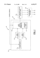
- FIG. 1 is a schematic view of a high energy remote source lighting system according to the present invention, the system being capable of providing dimmed and/or colored light;
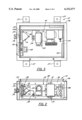
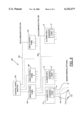
- FIG. 2 is a side elevational view of an illuminator according to the present invention.
- FIG. 3 is a top plan view of the illuminator shown in FIG. 2;
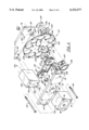
- FIG. 4 is an exploded perspective view of a light output modifying apparatus according to the present invention and included in the system of FIG. 1 and in the illuminator of FIG. 2;
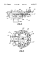
- FIG. 5 is a top plan view of the light output modifying apparatus shown in FIG. 4;
- FIG. 6 is a front elevational view of the light output modifying apparatus shown in FIG. 5;
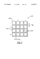
- FIG. 7 is a schematic view of a 2-D binary quasi-periodical structure according to the present invention.
- FIG. 8 is schematic view of a remote lighting system including a plurality of illuminators according to the present invention.
- a remote source lighting system 10 that provides high energy lighting includes an illuminator 12 having as its primary components a power supply 14 and one, and possibly two light sources 16, 18.
- the power supply 14 is controlled by control signals, transmitted by a system controller (not shown in FIG. 1) to selectively supply power to the first light source 16, and optionally to the second light source 18 (if present).
- Light source 16 is a high energy source such as a metal-halide lamp. In operation, light source 16 (and/or light source 18) directs light energy toward an output end 22 of illuminator 12. Light output from illuminator 12 is then coupled to a light delivery system 24.
- Light delivery system 24 preferably comprises a plurality of fiber optic cables 144 having a distal end 172 (see, e.g., FIGS. 3 and 8) for providing light energy to a plurality of lighting points strategically dispersed over a designated area, e.g., over particular regions of a navel ship.
- light delivery system 24 is connected to a plurality of beamformers 173 connected to the fiber optic cables 144 at their distal ends 172 for shaping the output light depending upon user requirements.
- Illuminator 12 also includes a selectively positionable light output modifying apparatus 20 that is optically coupled to light source 16 such that apparatus 20 is disposed downstream of the light source 16 in the direction of light energy propagation.
- Light output modifying apparatus 20 is configured to dim, color or otherwise modify the light energy emitted by light source 16.
- Operation of apparatus 20 preferably is controlled by a controller (e.g., a control card 21) that generates an output control signal in response to input control signals generated by a system controller (not shown) such that illuminator 12 outputs light having particular, user-selected characteristics.
- illuminator 12 includes a housing 26 within which the components of the illuminator are mounted. Housing 26 preferably has a plurality of mounting flanges 27 having apertures for receiving fasteners for appropriately mounting and stabilizing illuminator 12 on a support.
- Power supply 14 is mounted in the housing 26 and includes a transformer 28 that is mounted to a sidewall 30 of housing 26 with fasteners 31, e.g., rivets. Transformer 28 is coupled to a central source of power (not shown) for supplying power to illuminator 12.
- Power supply 14 also includes a capacitor 32 and an ignitor 33 that collectively receive power from transformer 28 and operate to actuate light source 16.
- a terminal 34 is provided for electrically coupling power supply 14 to light source 16.
- power supply 14 could be a electronic ballast or any other suitable power source.
- Light source 16 is secured to housing 26 via a light mounting structure 38.
- a safety power switch 40 is also included to allow the user to deactivate the illuminator 12 as desired.
- Coupler 35 couples concentrated light into a fiber optic cable bundle of light delivery system 24 (FIG. 1), the optical cables of light delivery system 24 being connected to a connector 36.
- a light output modifying apparatus 20 having a movable device 72 (described below) mounted to housing 26. Further, a filter 39 (e.g., infrared) is preferably disposed between light source 16 and apparatus 20 for maximizing the efficiency of the transmission of the selected type of light.
- Illuminator 12 also preferably includes a control card 21 (FIG. 1) electrically coupled to light output modifying apparatus 20, preferably via a ribbon cable, for positioning apparatus 20 in response to input control signals transmitted by a system computer (not shown).
- Illuminator 12 also includes an electrical terminal bus 44 that receives control/power signals that have been transmitted, preferably, from a remote location.
- Illuminator 12 also includes a fan 42 for cooling the heat generating components of the system such as the electronic components. Also shown in FIG. 3 is a stepper motor 58 that is used to drive apparatus 20 (see below discussion). The operational aspects of these components will be described in more detail below.
- Apparatus 20 includes a torque transfer assembly 50 having a drive pulley 52 and a driven pulley 54 coupled to each other via a belt 63 made of, for example, a suitable rubber material.
- Drive pulley 52 includes a hub 60 for receiving a first end of a drive shaft 56 that is mechanically connected to the stepper motor 58 at its opposite end.
- driven pulley 54 includes a hub 62 for receiving a first end 76 of a driven shaft 64 that has a second end 66 rotatably journaled in a bearing (not shown) mounted in a hole 70 in front plate 68.
- driven shaft 64 extends through and is attached to a movable device 72, e.g., a rotatable disk having a hub portion 74. At its first end 76, driven shaft 64 is rotatabaly journaled in an opening 80 of a back plate 78 via a bearing 82. Back plate 78 is mounted to studs 100, 102 attached to housing wall 29. Driven shaft 64 is keyed or otherwise affixed to the hub portion 74 of the movable device 72. In operation, driven shaft 64 rotates device 72 in response to an output force delivered by motor 58 in response to particular control signals transmitted by the system computer.
- a movable device 72 e.g., a rotatable disk having a hub portion 74.
- driven shaft 64 is rotatabaly journaled in an opening 80 of a back plate 78 via a bearing 82. Back plate 78 is mounted to studs 100, 102 attached to housing wall 29.
- Driven shaft 64 is keyed or otherwise af
- Torque transfer assembly 50 and movable device 72 are preferably sandwiched between the front and back plates 68, 78, respectively, while the drive pulley 52 is separated from front plate 68 by a bushing 84.
- bushings 88, 90 and shaft 64 separate driven pulley 54 from front plate 68 and disk 72, respectively, to maintain the integrity of the mechanical interconnections and ensure proper operation of torque transfer assembly 50.
- Bushings 84, 88, 90 each have a threaded radial opening 87, 89, 91, respectively, for accommodating a set screw (not shown) that secures bushings 84, 88, 90 to their respective shafts such that the bushings rotate with their corresponding shaft, thus reducing operational wear on shafts 56, 64.
- Motor 58 is configured with a plurality of openings 96 alignable with a plurality of threaded openings 97 in front plate 68 for securing motor 58 to front plate 68 with a plurality of threaded bolts 98.
- Front plate 68 is preferably mounted to the floor of housing 26 (FIGS. 2 and 3) in conventional fashion for stabilizing apparatus 20, and particularly motor 58.
- a support block 104 is positioned between front and back plates 68 and 78 such that planar end faces 108, 110 of block 104 abut flush against plates 68, 78, respectively, and such that openings 106 in the block 104 align with corresponding openings 112, 114 of front and back plates 68, 78.
- front and back plates 68, 78 can be clamped together by tightening a plurality of threaded bolts 116 (openings 114 preferably being threaded to accommodate bolts 116).
- Movable device 72 includes a plurality of generally circular openings 120 equally spaced around its perimeter, each opening 120 accommodating a different type of light output modifying element 122. As shown in FIG. 4, each element 122 is a light-intensity controlling filter dimming the light energy.
- Rotatable disk 72 includes a plurality of studs 124 (for example, two per opening) for retaining light output modifying elements 122.
- each set of studs 124 is threaded and configured to accommodate a retainer ring 126 which is attached to the disk 72 via threaded nuts which are adapted to be fastened to the corresponding studs 124.
- each element 122 can be readily replaced or changed to a different type of light output modifying element, e.g., a color filter.
- Disk 72 includes front and back support members 130, 132 fixedly secured thereto, members 130, 132 having hubs 134, 136, respectively. Because disk 72 is relatively thin, members 130, 132 provide support to minimize mechanical noise and ensure the integrity of optical alignment between the light source 16 (FIGS. 1-3) and the selected light output modifying element 122. As shown in FIG. 4, movable device 72 is positioned such that one of the light output modifying elements 122 is aligned with an output port 140 of housing 26. Consequently, light from light source 16 (FIGS. 1-4) must pass through the selected element 22 prior to being coupled to optical coupler 142, and more specifically to fiber optic bundle 144.
- motor 58 is responsive to control signals indicative of a desired output light, e.g., dimmed, colored, etc., the signals being transmitted from an illuminator control card (21 in FIG. 1) in response to input control signals from a computer disposed at a remote location.
- motor 58 rotates drive shaft 56, thus causing drive pulley 52, and therefore belt 63, to move.
- driven pulley 54 rotates.
- the rotation of driven pulley 54 correspondingly rotates driven shaft 64 and movable device 72 attached thereto to align a selected one of the elements 122 with output port 140.
- movable device 72 When device 72 is in a selected position, light energy from the light source 16 can be directed generally through the selected opening 120 containing the element 122 for appropriately modifying the light.
- movable device 72 and more particularly the selected light output modifying element 122, couples light received from the light source 16 to the fiber optic bundle 144, thus providing light having desired characteristics to predetermined lighting points.
- FIG. 5 a fully assembled and mounted view of light output modifying apparatus 20 of illuminator 12 is shown.
- back plate 78 of apparatus 20 is preferably bolted to a perimeter wall 29 of housing 26 with appropriate fasteners 100, 102, e.g., stud members, and is separated from wall 29 via spacers 142, 143 associated with each stud 100, 102, respectively, to isolate apparatus 20 from housing 26 and minimize the effects of mechanical noise.
- Front plate 68 is coupled to a rearward facing wall 86 of the enclosure of stepper motor 58 and includes a passageway 59 within which drive shaft 56 can rotate.
- apparatus 20 maintains the stability of movable device 72 (i.e., disk) such that light energy propagating through one of openings 120 (FIG. 4) of disk 72 is not refracted or altered in any other way prior to being coupled to output port 140.
- movable device 72 i.e., disk
- each of the light output modifying elements 122 is readily removable for repair, or for replacement with a different type of element that may produce any of a variety of output light characteristics.
- a light intensity filtering element (described below with reference to FIG. 7) or a color filter element may be interchanged with a light blocking element 122a for impeding the coupling of light from the source, or with a transparent element 122b (or left empty) for permitting 100% of the light energy to be coupled to optical coupler 35.
- FIG. 7 illustrates a preferred construction of a light modifying element 122 having a two-dimensional binary quasi-periodical structure 150.
- Structure 150 provides a relatively inexpensive device for modifying the output light, e.g., by dimming the input light, according to user specifications.
- Two-dimensional binary quasi-periodical structures 150 of the preferred embodiment preferably consist of a predetermined number of transparent and non-transparent elements 152, 154, respectively. Structures 150 offer significant advantages over known alternatives for dimming light, such as absorption optical filters, which are not practical in high power lighting systems due to poor performance relating heat resistance requirements and unacceptably high manufacturing costs.
- structures 150 provide advantages over other types of known devices, such as reflective optical filters (which exhibit problems relating to light source and reflective performance), and changeable aperture devices (having calibrated windows, irises and slots which in simple versions cannot provide the required accuracy, in more sophisticated versions, become bulky and prohibitively expensive).
- two-dimensional binary quasi-periodical structures 150 By using two-dimensional binary quasi-periodical structures 150, one single structure or a combination of several such structures can provide a wide range of light energy attenuation with high accuracy and minimal manufacturing expense. Such structures are particularly useful in systems with non-trivial two-dimensional light distribution, and particularly for RSL systems where the light produced by the optics subsystem (i.e., illuminator) is coupled into a fiber bundle (144 in FIG. 4) that has precalculated randomization.
- a characteristic of 2-D binary quasi-periodical structures 150 of FIG. 6 is defined by an attenuation coefficient A k (x,y) that can be derived from the transparency T k (x,y).
- Attentuator structures 150 can be combined, preferably by stacking structures 150 flush against one another to create an element 122 for producing output light energy having a desired characteristic, such that for any combination of k structures, the total attenuation coefficient A k (x,y) can be calculated by the following equation: ##EQU2##
- an attenuating light modifying element 122 should not be disposed intermediate the light source and optical connector (i.e., element 122b shown in FIG. 6 is disposed between the light source and optical connector) because the intensity of the source light should not be attenuated at all, thus allowing 100% of the intensity of the light to be coupled to the output of illuminator 12.
- 2-D quasi-periodical structures may be designed to produce particular output light by modifying the appropriate variables of Equations (1) and (2). Further, such structures may be formed to correspond to any shape of opening 120 of disk 72 (FIG. 4). As mentioned previously, openings 120 in disk 72 can also include a filter, for example, a standard off-the-shelf type optical filter, for modifying the color of the output light transmitted by illuminator 12, and such a filter can be further combined with dimming structures 150 to produce the desired output light.
- a filter for example, a standard off-the-shelf type optical filter
- a remote lighting system (RLS) 160 which includes a plurality of illuminators 12 according to the preferred embodiment (i.e., which have a corresponding light output modifying apparatus 20 capable of providing light having selected characteristics).
- a master control panel 162 e.g., a bridge control panel or air traffic control tower
- Area control panels 164 can be user controlled and/or programmably controlled to output control signals indicative of a selected type of light to individual illuminators 12 via another telecommunication link 168.
- individual area control panels 164 provide an efficient way of controlling respective illuminators 12 to achieve the particular lighting desired, i.e., without having to operate bridge control panel 162 or to individually operate illuminators 12 or the individual lighting points (not shown).
- a user situated at bridge control panel 162 can operate a control board for instructing area control panels 164 to generate output signals indicative of lighting desired.
- control card 21 of each illuminator generates a control signal that the illuminator 12 transmits to the motor 58 (FIG. 4) of the associated light output modifying apparatus 20.
- motor 58 positions movable device 72 (FIGS. 4-6) such that the output light (having desired characteristics, e.g., dimmed or colored light) from that illuminator 12 is coupled to optical cables 144.
- Each one of optical cables 144 includes a distal end 172 for providing light to strategically placed lighting points in the lighted area (not shown). Note that distal ends 172 may or may not include a beamformer 173 for shaping the outgoing light into a desired pattern, as shown and described in U.S. Pat. No.
- each illuminator 12 can be remotely controlled by either individual area control panels 164 or by a master bridge control panel 162 to provide the most efficient distribution of light according to specific user requirements.
Abstract
Description
              TABLE 1
______________________________________
m × n  δ.sub.m, δ.sub.n
                        Transparency %
Type    (per inch)
                 (inch)     Calculated
                                   Measured
______________________________________
A       18 × 18
                 0.017      48.3   48.6
B       30 × 30
                 0.01       45.3   45.7
C       150 × 150
                 0.026      39.9   40.3
D       250 × 250
                 0.016      36.0   39.6
E       400 × 400
                 0.01       35.0   29.7
F       50 × 50
                 0.09       30.3   28.7
G       60 × 60
                 0.075      30.0   28.6
H       500 × 500
                 0.01       25.0   27.3
______________________________________
              TABLE 2
______________________________________
Required    Combination of Transparency %
Step  Intensity (%)
                Attneuator Structures
                               Calculated
                                      Measured
______________________________________
B-5   100       --             --     --
B-4   20        B + B          20.5   20.0
B-3   4         A + B + C      3.99   4.0
B-2   0.8       F + F + G + G  0.85   0.81
B-1   0.16      A + E + F + G + H
                               0.2    0.16
______________________________________
Claims (18)
Priority Applications (1)
| Application Number | Priority Date | Filing Date | Title |
|---|---|---|---|
| US09/166,052 US6152577A (en) | 1998-10-05 | 1998-10-05 | Remote illumination system having a light output modifying apparatus |
Applications Claiming Priority (1)
| Application Number | Priority Date | Filing Date | Title |
|---|---|---|---|
| US09/166,052 US6152577A (en) | 1998-10-05 | 1998-10-05 | Remote illumination system having a light output modifying apparatus |
Publications (1)
| Publication Number | Publication Date |
|---|---|
| US6152577A true US6152577A (en) | 2000-11-28 |
Family
ID=22601607
Family Applications (1)
| Application Number | Title | Priority Date | Filing Date |
|---|---|---|---|
| US09/166,052 Expired - Lifetime US6152577A (en) | 1998-10-05 | 1998-10-05 | Remote illumination system having a light output modifying apparatus |
Country Status (1)
| Country | Link |
|---|---|
| US (1) | US6152577A (en) |
Cited By (28)
| Publication number | Priority date | Publication date | Assignee | Title |
|---|---|---|---|---|
| US6283623B1 (en) * | 1999-10-27 | 2001-09-04 | Visteon Global Tech., Inc. | Method and apparatus for remote lighting |
| US6382824B1 (en) * | 1997-06-02 | 2002-05-07 | Fiberstars Incorporated | Fiber optics illuminators and lighting system |
| US6504984B1 (en) * | 2000-11-21 | 2003-01-07 | Us Sign And Fabrication Ccorporation | Apparatus for delivering smoothed light from an uneven source |
| US6565233B1 (en) * | 1999-08-17 | 2003-05-20 | Brian Edward Richardson | Color, size and distribution module for projected light |
| US6601973B2 (en) * | 2000-06-26 | 2003-08-05 | Martin Professional A/S | Light effects system |
| US20030206650A1 (en) * | 2002-05-02 | 2003-11-06 | Mitutoyo Corporation | Systems and methods for continuously varying wavelength illumination |
| US20080247163A1 (en) * | 2007-04-04 | 2008-10-09 | Lien-Chen Chen | Operating lamp with adjustable light sources capable of generating a light field of a gaussian distribution |
| US9084314B2 (en) | 2006-11-28 | 2015-07-14 | Hayward Industries, Inc. | Programmable underwater lighting system |
| CN106114892A (en) * | 2016-07-25 | 2016-11-16 | 无锡昊瑜节能环保设备有限公司 | A kind of control method of airport pavement illuminator |
| WO2017103757A1 (en) * | 2015-12-17 | 2017-06-22 | Novartis Ag | Beam guide for ophthalmic surgical illumination |
| US20170213451A1 (en) | 2016-01-22 | 2017-07-27 | Hayward Industries, Inc. | Systems and Methods for Providing Network Connectivity and Remote Monitoring, Optimization, and Control of Pool/Spa Equipment |
| US9723677B2 (en) | 2015-05-20 | 2017-08-01 | Goodrich Lighting Systems Gmbh | Aircraft landing light unit, exterior aircraft lighting system and method of operating an aircraft landing light unit |
| USD804083S1 (en) | 2014-10-30 | 2017-11-28 | Telebrands Corp. | Landscape light |
| US9869459B2 (en) | 2014-07-16 | 2018-01-16 | Telebrands Corp. | Landscape light |
| US9879847B2 (en) | 2015-12-03 | 2018-01-30 | Telebrands Corp. | Decorative lighting apparatus having two laser light sources |
| USD816890S1 (en) | 2015-05-11 | 2018-05-01 | Telebrands Corp. | Light projector |
| USD820507S1 (en) | 2015-05-11 | 2018-06-12 | Telebrands Corp. | Light projector |
| USD824066S1 (en) | 2015-05-11 | 2018-07-24 | Telebrands Corp. | Light projector |
| EP3361149A1 (en) * | 2017-02-10 | 2018-08-15 | Harman Professional Denmark ApS | Method of reducing sound from light fixture with stepper motors |
| US10057964B2 (en) | 2015-07-02 | 2018-08-21 | Hayward Industries, Inc. | Lighting system for an environment and a control module for use therein |
| USD828618S1 (en) | 2015-05-11 | 2018-09-11 | Telebrands Corp. | Light projector |
| EP3257136A4 (en) * | 2015-02-09 | 2018-09-19 | Cooper Technologies Company | Uninterruptible constant current regulator |
| US10182481B2 (en) | 2016-04-26 | 2019-01-15 | RAB Lighting Inc. | Bi-level low voltage dimming controller for lighting drivers |
| US10718507B2 (en) | 2010-04-28 | 2020-07-21 | Hayard Industries, Inc. | Underwater light having a sealed polymer housing and method of manufacture therefor |
| US20200319621A1 (en) | 2016-01-22 | 2020-10-08 | Hayward Industries, Inc. | Systems and Methods for Providing Network Connectivity and Remote Monitoring, Optimization, and Control of Pool/Spa Equipment |
| US10976713B2 (en) | 2013-03-15 | 2021-04-13 | Hayward Industries, Inc. | Modular pool/spa control system |
| US11168876B2 (en) | 2019-03-06 | 2021-11-09 | Hayward Industries, Inc. | Underwater light having programmable controller and replaceable light-emitting diode (LED) assembly |
| EP4317769A1 (en) | 2022-08-04 | 2024-02-07 | Sunland Optics Srl | A gobo projector and a method for using a gobo projector |
Citations (6)
| Publication number | Priority date | Publication date | Assignee | Title |
|---|---|---|---|---|
| US4043646A (en) * | 1975-09-17 | 1977-08-23 | Propper Manufacturing Co., Inc. | Filter mechanism with interconnected heat and color filters for optical examination devices |
| US5534704A (en) * | 1993-04-21 | 1996-07-09 | Sharp Kabushiki Kaisha | Optical image correlator and system for performing parallel correlation |
| US5779353A (en) * | 1996-04-16 | 1998-07-14 | Fiberstars, Inc. | Weather-protected lighting apparatus and method |
| US5825440A (en) * | 1994-12-07 | 1998-10-20 | Samsung Display Devices Co., Ltd. | Liquid crystal display backlighting system which includes dichroic mirrors, optical light valves, transmission tubes, and a light transmission plate |
| US5877681A (en) * | 1995-02-02 | 1999-03-02 | Federal Signal Corporation | System and method for broadcasting colored light for emergency signalling |
| US5917405A (en) * | 1993-06-08 | 1999-06-29 | Joao; Raymond Anthony | Control apparatus and methods for vehicles |
-
1998
- 1998-10-05 US US09/166,052 patent/US6152577A/en not_active Expired - Lifetime
Patent Citations (6)
| Publication number | Priority date | Publication date | Assignee | Title |
|---|---|---|---|---|
| US4043646A (en) * | 1975-09-17 | 1977-08-23 | Propper Manufacturing Co., Inc. | Filter mechanism with interconnected heat and color filters for optical examination devices |
| US5534704A (en) * | 1993-04-21 | 1996-07-09 | Sharp Kabushiki Kaisha | Optical image correlator and system for performing parallel correlation |
| US5917405A (en) * | 1993-06-08 | 1999-06-29 | Joao; Raymond Anthony | Control apparatus and methods for vehicles |
| US5825440A (en) * | 1994-12-07 | 1998-10-20 | Samsung Display Devices Co., Ltd. | Liquid crystal display backlighting system which includes dichroic mirrors, optical light valves, transmission tubes, and a light transmission plate |
| US5877681A (en) * | 1995-02-02 | 1999-03-02 | Federal Signal Corporation | System and method for broadcasting colored light for emergency signalling |
| US5779353A (en) * | 1996-04-16 | 1998-07-14 | Fiberstars, Inc. | Weather-protected lighting apparatus and method |
Cited By (54)
| Publication number | Priority date | Publication date | Assignee | Title |
|---|---|---|---|---|
| US6382824B1 (en) * | 1997-06-02 | 2002-05-07 | Fiberstars Incorporated | Fiber optics illuminators and lighting system |
| US6565233B1 (en) * | 1999-08-17 | 2003-05-20 | Brian Edward Richardson | Color, size and distribution module for projected light |
| US6283623B1 (en) * | 1999-10-27 | 2001-09-04 | Visteon Global Tech., Inc. | Method and apparatus for remote lighting |
| US6601973B2 (en) * | 2000-06-26 | 2003-08-05 | Martin Professional A/S | Light effects system |
| US6504984B1 (en) * | 2000-11-21 | 2003-01-07 | Us Sign And Fabrication Ccorporation | Apparatus for delivering smoothed light from an uneven source |
| US20030206650A1 (en) * | 2002-05-02 | 2003-11-06 | Mitutoyo Corporation | Systems and methods for continuously varying wavelength illumination |
| US7016525B2 (en) | 2002-05-02 | 2006-03-21 | Mitutoyo Corporation | Systems and methods for continuously varying wavelength illumination |
| US9084314B2 (en) | 2006-11-28 | 2015-07-14 | Hayward Industries, Inc. | Programmable underwater lighting system |
| US20080247163A1 (en) * | 2007-04-04 | 2008-10-09 | Lien-Chen Chen | Operating lamp with adjustable light sources capable of generating a light field of a gaussian distribution |
| US7562999B2 (en) * | 2007-04-04 | 2009-07-21 | Mediland Enterprise Corporation | Operating lamp with adjustable light sources capable of generating a light field of a Gaussian distribution |
| US10718507B2 (en) | 2010-04-28 | 2020-07-21 | Hayard Industries, Inc. | Underwater light having a sealed polymer housing and method of manufacture therefor |
| US11822300B2 (en) | 2013-03-15 | 2023-11-21 | Hayward Industries, Inc. | Modular pool/spa control system |
| US10976713B2 (en) | 2013-03-15 | 2021-04-13 | Hayward Industries, Inc. | Modular pool/spa control system |
| US9874327B2 (en) | 2014-07-16 | 2018-01-23 | Telebrands Corp. | Landscape light |
| US10197234B2 (en) | 2014-07-16 | 2019-02-05 | Telebrands Corp. | Landscape light |
| US10228113B2 (en) | 2014-07-16 | 2019-03-12 | Telebrands Corp. | Landscape light |
| US9869459B2 (en) | 2014-07-16 | 2018-01-16 | Telebrands Corp. | Landscape light |
| USD804715S1 (en) | 2014-10-30 | 2017-12-05 | Telebrands Corp. | Landscape light |
| USD804083S1 (en) | 2014-10-30 | 2017-11-28 | Telebrands Corp. | Landscape light |
| US10516294B2 (en) | 2015-02-09 | 2019-12-24 | Eaton Intelligent Power Limited | Uninterruptible constant current regulator |
| EP3257136A4 (en) * | 2015-02-09 | 2018-09-19 | Cooper Technologies Company | Uninterruptible constant current regulator |
| USD816890S1 (en) | 2015-05-11 | 2018-05-01 | Telebrands Corp. | Light projector |
| USD820507S1 (en) | 2015-05-11 | 2018-06-12 | Telebrands Corp. | Light projector |
| USD821023S1 (en) | 2015-05-11 | 2018-06-19 | Telebrands Corp. | Light projector |
| USD824066S1 (en) | 2015-05-11 | 2018-07-24 | Telebrands Corp. | Light projector |
| USD828618S1 (en) | 2015-05-11 | 2018-09-11 | Telebrands Corp. | Light projector |
| USD828619S1 (en) | 2015-05-11 | 2018-09-11 | Telebrands Corp. | Light projector |
| US9723677B2 (en) | 2015-05-20 | 2017-08-01 | Goodrich Lighting Systems Gmbh | Aircraft landing light unit, exterior aircraft lighting system and method of operating an aircraft landing light unit |
| US11632835B2 (en) | 2015-07-02 | 2023-04-18 | Hayward Industries, Inc. | Lighting system for an environment and a control module for use therein |
| US10057964B2 (en) | 2015-07-02 | 2018-08-21 | Hayward Industries, Inc. | Lighting system for an environment and a control module for use therein |
| US10588200B2 (en) | 2015-07-02 | 2020-03-10 | Hayward Industries, Inc. | Lighting system for an environment and a control module for use therein |
| US9879847B2 (en) | 2015-12-03 | 2018-01-30 | Telebrands Corp. | Decorative lighting apparatus having two laser light sources |
| WO2017103757A1 (en) * | 2015-12-17 | 2017-06-22 | Novartis Ag | Beam guide for ophthalmic surgical illumination |
| US10188481B2 (en) | 2015-12-17 | 2019-01-29 | Novartis Ag | Beam guide for ophthalmic surgical illumination |
| CN108366722A (en) * | 2015-12-17 | 2018-08-03 | 诺华股份有限公司 | Beam guide part for eye surgery illumination |
| US20170213451A1 (en) | 2016-01-22 | 2017-07-27 | Hayward Industries, Inc. | Systems and Methods for Providing Network Connectivity and Remote Monitoring, Optimization, and Control of Pool/Spa Equipment |
| US11129256B2 (en) | 2016-01-22 | 2021-09-21 | Hayward Industries, Inc. | Systems and methods for providing network connectivity and remote monitoring, optimization, and control of pool/spa equipment |
| US10363197B2 (en) | 2016-01-22 | 2019-07-30 | Hayward Industries, Inc. | Systems and methods for providing network connectivity and remote monitoring, optimization, and control of pool/spa equipment |
| US10272014B2 (en) | 2016-01-22 | 2019-04-30 | Hayward Industries, Inc. | Systems and methods for providing network connectivity and remote monitoring, optimization, and control of pool/spa equipment |
| US10219975B2 (en) | 2016-01-22 | 2019-03-05 | Hayward Industries, Inc. | Systems and methods for providing network connectivity and remote monitoring, optimization, and control of pool/spa equipment |
| US20200319621A1 (en) | 2016-01-22 | 2020-10-08 | Hayward Industries, Inc. | Systems and Methods for Providing Network Connectivity and Remote Monitoring, Optimization, and Control of Pool/Spa Equipment |
| US11000449B2 (en) | 2016-01-22 | 2021-05-11 | Hayward Industries, Inc. | Systems and methods for providing network connectivity and remote monitoring, optimization, and control of pool/spa equipment |
| US11720085B2 (en) | 2016-01-22 | 2023-08-08 | Hayward Industries, Inc. | Systems and methods for providing network connectivity and remote monitoring, optimization, and control of pool/spa equipment |
| US11096862B2 (en) | 2016-01-22 | 2021-08-24 | Hayward Industries, Inc. | Systems and methods for providing network connectivity and remote monitoring, optimization, and control of pool/spa equipment |
| US11122669B2 (en) | 2016-01-22 | 2021-09-14 | Hayward Industries, Inc. | Systems and methods for providing network connectivity and remote monitoring, optimization, and control of pool/spa equipment |
| US10182481B2 (en) | 2016-04-26 | 2019-01-15 | RAB Lighting Inc. | Bi-level low voltage dimming controller for lighting drivers |
| CN106114892A (en) * | 2016-07-25 | 2016-11-16 | 无锡昊瑜节能环保设备有限公司 | A kind of control method of airport pavement illuminator |
| CN108413343B (en) * | 2017-02-10 | 2021-07-09 | 哈曼专业丹麦公司 | Method of reducing sound from a luminaire having a stepper motor |
| CN108413343A (en) * | 2017-02-10 | 2018-08-17 | 哈曼专业丹麦公司 | Reduce the method for the sound from the lamps and lanterns with stepper motor |
| US10340782B2 (en) | 2017-02-10 | 2019-07-02 | Harman Professional Denmark Aps | Method of reducing sound from light fixture with stepper motors |
| EP3361149A1 (en) * | 2017-02-10 | 2018-08-15 | Harman Professional Denmark ApS | Method of reducing sound from light fixture with stepper motors |
| US11168876B2 (en) | 2019-03-06 | 2021-11-09 | Hayward Industries, Inc. | Underwater light having programmable controller and replaceable light-emitting diode (LED) assembly |
| US11754268B2 (en) | 2019-03-06 | 2023-09-12 | Hayward Industries, Inc. | Underwater light having programmable controller and replaceable light-emitting diode (LED) assembly |
| EP4317769A1 (en) | 2022-08-04 | 2024-02-07 | Sunland Optics Srl | A gobo projector and a method for using a gobo projector |
Similar Documents
| Publication | Publication Date | Title |
|---|---|---|
| US6152577A (en) | Remote illumination system having a light output modifying apparatus | |
| US5143433A (en) | Night vision backlighting system for liquid crystal displays | |
| US5647658A (en) | Fiber-optic lighting system | |
| US4912334A (en) | Infrared aircraft beacon light | |
| US5886681A (en) | Wide-range dual-backlight display apparatus | |
| US8337206B2 (en) | Tool for assisting in the design of an aircraft flight deck compatible with a night vision system | |
| EP0894220A1 (en) | Method and apparatus for controlling light | |
| JP3449720B2 (en) | Color liquid crystal display backlight system compatible with night light imaging system | |
| US6846099B2 (en) | Aircraft position light | |
| US4217625A (en) | Lighted instrument dial face display | |
| US20100244748A1 (en) | Rotating beacon | |
| US4904991A (en) | Display unit subject to ambient light having light-reflective and light-emitting display elements | |
| US20020114161A1 (en) | Rotating warning lamp having a planar light source | |
| US7012542B2 (en) | Multicolor function indicator light | |
| GB2051447A (en) | Optical display apparatus | |
| JP2009302063A (en) | Beam former for remote lighting method and device | |
| US5508892A (en) | Light processing apparatus for creating visual effects | |
| US20050099791A1 (en) | Backlighting system for liquid crystal displays | |
| US5563588A (en) | Fiber optic traffic signal light system having a shutter control | |
| JP3165388B2 (en) | Display device and lighting device | |
| US5619194A (en) | Fiber optic traffic signal light system having a shutter control | |
| DE10142582B4 (en) | Bulb signal element, light signal device and light signal system | |
| RU2248025C2 (en) | Light diode projector and method for presenting information on display | |
| US5926265A (en) | Low-level lighting comparator | |
| EP0510421A2 (en) | Multi-coloured light indicator |
Legal Events
| Date | Code | Title | Description |
|---|---|---|---|
| AS | Assignment |
Owner name: FARLIGHT CORPORATION, CALIFORNIA Free format text: ASSIGNMENT OF ASSIGNORS INTEREST;ASSIGNORS:RIZKIN, ALEXANDER;DURETS, YEVGENIY Y.;OBERG, CARL E.;AND OTHERS;REEL/FRAME:009852/0852 Effective date: 19990318 |
|
| AS | Assignment |
Owner name: PHYSICAL OPTICS CORPORATION, CALIFORNIA Free format text: ASSIGNMENT OF ASSIGNORS INTEREST;ASSIGNOR:FARLIGHT CORPORATION;REEL/FRAME:010618/0787 Effective date: 19991231 |
|
| STCF | Information on status: patent grant |
Free format text: PATENTED CASE |
|
| REMI | Maintenance fee reminder mailed | ||
| FPAY | Fee payment |
Year of fee payment: 4 |
|
| SULP | Surcharge for late payment | ||
| AS | Assignment |
Owner name: LUMINIT, L.L.C., CALIFORNIA Free format text: ASSIGNMENT OF ASSIGNORS INTEREST;ASSIGNOR:PHYSICAL OPTICS CORPORATION;REEL/FRAME:019495/0546 Effective date: 20070625 |
|
| FEPP | Fee payment procedure |
Free format text: PAT HOLDER NO LONGER CLAIMS SMALL ENTITY STATUS, ENTITY STATUS SET TO UNDISCOUNTED (ORIGINAL EVENT CODE: STOL); ENTITY STATUS OF PATENT OWNER: LARGE ENTITY |
|
| FPAY | Fee payment |
Year of fee payment: 8 |
|
| AS | Assignment |
Owner name: ASAHI KASEI KABUSHIKI KAISAH, JAPAN Free format text: ASSIGNMENT OF ASSIGNORS INTEREST;ASSIGNOR:LUMINIT LLC;REEL/FRAME:023525/0630 Effective date: 20090928 Owner name: ASAHI KASEI KABUSHIKI KAISHA,JAPAN Free format text: ASSIGNMENT OF ASSIGNORS INTEREST;ASSIGNOR:LUMINIT LLC;REEL/FRAME:023525/0630 Effective date: 20090928 Owner name: ASAHI KASEI KABUSHIKI KAISHA, JAPAN Free format text: ASSIGNMENT OF ASSIGNORS INTEREST;ASSIGNOR:LUMINIT LLC;REEL/FRAME:023525/0630 Effective date: 20090928 |
|
| FEPP | Fee payment procedure |
Free format text: PAYOR NUMBER ASSIGNED (ORIGINAL EVENT CODE: ASPN); ENTITY STATUS OF PATENT OWNER: LARGE ENTITY |
|
| FPAY | Fee payment |
Year of fee payment: 12 |
|
| AS | Assignment |
Owner name: LUMINIT LLC, CALIFORNIA Free format text: ASSIGNMENT OF ASSIGNORS INTEREST;ASSIGNOR:ASAHI KASEI KABUSHIKI KAISHA;REEL/FRAME:030680/0827 Effective date: 20130613 |